基于BTF340开发评估板的USB通信程序
C8051F340 USB通信

题目:
基于 USB 的无线测控平台的设计
姓 名: 向东游 院(系 ):机械与电子信息学院 指导教师: 黄玉金 评 阅 人: 莫文琴
学号: 20061003481 专业: 测控技术与仪器 职称: 讲师 职称: 讲师
2010 年 6 月
学位论文原创性声明
本人郑重声明:所呈交的论文是本人在导师的指导下独立进行研究所取
From modular, reusable software engineering idea, the platform’s software code for the functional unit involved in or interface protocols has been made to integrated, modular and versatile package. This paper introduces the package library function name, formal parameters, return values and the achievement of the function. briefly.
目录
第一章 前言......................................................................................................................... 1 §1.1 研究目的与意义..................................................................................................... 1 1.1.1 课题的提出................................................................................................... 1 1.1.2 研究的意义................................................................................................... 1 §1.2 设计任务及要求..................................................................................................... 2
BT401蓝牙模块spiflash播放的串口控制命令和下载的说明

一、简介方案支持外挂spiflash,用来存储音乐或者语音。
支持通过芯片的USB端口直接拷贝MP3文件至外挂的spiflash 中,实现方式是将spiflash虚拟成U盘,像拷贝U盘一样拷贝文件进去。
无需驱动,无需任何上位机。
1、BT401模块测试板,需要flash,这需要自己焊上flash,然后贴上电阻即可。
2、注意只要贴上了flash,TF卡功能就不能用了。
只能二选一。
因为他们共用了IO口3、使用的是PC3/PC4/PC5这三个脚。
PC3是CS PC4是CLK PC5就是DO二、串口指令和原理说明1、这里spiflash的管理,在我们的方案中,其实和TF卡、U盘是一样的,都可以称之为设备。
2、当切换至spiflash之后,那么芯片会释放掉TF卡或者U盘的驱动资源,全部资源就去加载spiflash的驱动(1)、如文件系统的读写接口,切换至spiflash(2)、音频解码的读接口,也切换至spiflash。
3、所以都可以串口AT指令去控制,比如:下一曲、上一曲、播放暂停、按照物理序号指定播放等等。
和TF卡以及U 盘的操作方式是一模一样4、如果需要使用spiflash,需要指定模式为spiflash即可,看看手册的CM指令5、切换至flash之后,就可以正常操作了。
注意,默认的DAC版本的才支持spiflash。
其他各种版本不支持三、支持的型号和拷贝语音说明请留意,拷贝语音到spiflash,是无需任何电脑端的软件,模块会自动虚拟spiflash为U盘,直接像拷贝U盘一样,拷贝音频文件进去即可3.1spiflash的硬件以及容量支持说明1、方案目前最大支持16M字节的FLASH。
换算为FLASH一般的型号,如:W25Q128型号容量封装W25Q801Mbyte SOP8L[宽体]W25Q162Mbyte SOP8L[宽体]W25Q324Mbyte SOP8L[宽体]W25Q648Mbyte SOP8L[宽体]W25Q12816Mbyte SOP8L[宽体]2、方案支持自动识别spiflash的容量大小。
基于C8051+F340单片机的USB数据采集系统

1 背景介绍 传统的数据采集设备与主机的通讯口一般采用RS232、
RS422或RS485等标准。当今的设备通讯口大多采用USB标 准…。作为一种新型的串口通信标准,基于USB接口的产品具 有较高的传输速率,可扩展性好,采用总线供电,支持热插拔 和即插即用等。特别是近几年来。USB大有完全取代上述标 准的趋势。
USB_Init(…);
Initialize();
p系统初始化},
USB_Int_Enable(); while(1){I 严循环等待相应中断到来+, l 3.2上位机软件设计
上位机软件在Delphi7.0环境下开发,通过主机(上位 机)的API函数调用动态链接库文件SiUSBXp.dll,启用应用 程序与设备驱动程序之间的通信。从而实现上位机与下位机 之间的数据通讯嘲。
满足API应用要求。所用到设备接口函数主要有:
USB Clock_.Start()
严初始化USB时钟}/
USB—Init()
产使能USB接口‘,
Block,Write() 严通过USB向主机写人数据’,
Block.Read()
严通过USB从主机读取数据宰,
Get_Interrupt Source()
USB Data Coilection System Based on MCU C8051F340
WANG Xiao—ning (Experimental[nstrmnent Factory,Academy of Military Medical Sciences,Beijing 100850,China) Abstract The characteristics of C805 1 F340 MCU and USB communication,and the design method of system's hardware and software stlllchII-e are introduced briefly.The whole system is proved stable and reliable by experiment.The Universal Serial Bus(USB)communication technology has great value in course of system design and study.【chinese Medical Equipment JournaI。2009,30(7):1 1 1-1 13] Key words C8051F340 MCU;USB2.O:USB bus;firmware;device drive program;client application
基于C8051F340单片机的USB数据采集系统

其共有 4 种传输模式:控制传输、同步传输、中断传输、 批量传输,以适应不同设备的需要。 本系统采用中断传输模 式。 中断传输(interrupt transfer)用于必须在指定时间内传输 完的数据上,支持高速/中速/低速的设备,能应用在一般数据 的传输上。Windows 包含启动设备中断传输的驱动程序,只要 设 备 符 合 HID(human interface device,人 机 接 口 设 备 )规 范 , 应用程序就可以执行设备的中断传输。 需要特别注意的是, 中断传输与其他 USB 传输一样,只发生在主机轮询设备的时 候,并不是由设备触发的硬件中断。
1 背景介绍 传统的 数 据 采 集 设 备 与 主 机 的 通 讯 口 一 般 采 用 RS232、
RS422 或 RS485 等标准,当今的设备通讯口大多采用 USB 标 准[1]。 作为一种新型的串口通信标准,基于 USB 接口的产品具 有较高的传输速率,可扩展性好,采用总线供电,支持热插拔 和即插即用等。 特别是近几年来,USB 大有完 全 取 代 上 述 标 准的趋势。
3.3 10 11 VDD 7 REGIN GND 8 D+ 9 D- 12 VBUS
C8051F340
图 1 下位机 USB 接口设计
terface,API), 编 程 就 能 实 现 USB 通 讯 控 制 功 能 。 图 2 是
BTool、PacketSniffer、BLE_Device_Monitor、USBDongle硬件手册
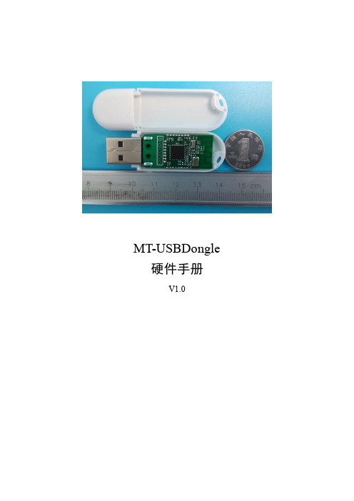
MT-USBDongle 硬件手册V1.0版本更新记录目录第1章产品介绍 (4)1.1蓝牙4.0简介 (4)1.2MT-USBDongle介绍 (4)第2章硬件资源 (5)2.1USBDongle正面 (5)2.2USBDongle反面 (5)2.3接口功能说明 (5)第3章技术规格说明 (7)3.1外观尺寸 (7)第4章开发事项 (8)附录A 产品实物图 (9)第1章产品介绍1.1 蓝牙4.0简介蓝牙4.0是2012年最新蓝牙版本,是3.0的升级版本;较3.0版本更省电、成本低、3毫秒低延迟、超长有效连接距离、AES-128加密等;通常用在蓝牙耳机、蓝牙音箱等设备上。
蓝牙4.0最重要的特性是省电,极低的运行和待机功耗可以使一粒纽扣电池连续工作数年之久。
此外,低成本和跨厂商互操作性,3毫秒低延迟、AES-128加密等诸多特色,可以用于计步器、心律监视器、智能仪表、传感器物联网等众多领域,大大扩展蓝牙技术的应用范围。
蓝牙4.0已经走向了商用,在最新款的Xperia Z、Galaxy S3、S4、Note2、SurfaceRT、iPhone 5、iPhone 4S、魅族MX3、Moto Droid Razr、HTC One X、小米手机2、The New iPad、iPad 4、MacBook Air、Macbook Pro,Nokia Lumia系列以及台商ACER AS3951系列/Getway NV57系列,ASUS UX21/31三星NOTE系列上都已应用了蓝牙4.0技术。
蓝牙4.0支持两种部署方式:双模式和单模式。
双模式中,低功耗蓝牙功能集成在现有的经典蓝牙控制器中,或再在现有经典蓝牙技术(2.1+EDR/3.0+HS)芯片上增加低功耗堆栈,整体架构基本不变,因此成本增加有限。
单模式面向高度集成、紧凑的设备,使用一个轻量级连接层(Link Layer)提供超低功耗的待机模式操作、简单设备恢复和可靠的点对多数据传输,还能让联网传感器在蓝牙传输中安排好低功耗蓝牙流量的次序,同时还有高级节能和安全加密连接。
基于C8051F340的USBXpress开发包USB通信设计
基于C8051F340的USBXpress开发包USB通信设计传统的USB设备驱动程序编写异常复杂,程序员往往很难入手。
Silicon Laborat ories公司提供的USBXpress开发包大大简化了USB通信的应用和相关驱动程序的开发,只要做好开发前的准备工作,USBXpress开发包完全可以实现USB通信的所有功能。
本文介绍USB通信开发的全过程,以及在开发过程中需要注意的事项。
(主要针对设备端USB通信进行讲解)1 USBXpress简介由Silicon Laboratories公司推出的USBXpress开发包涵盖了主机端和设备端的所有函数功能,支持C8051F32X、C8051F34X和CP210X设备的USB通信。
USBXpress开发包中包含主机端的设备驱动、主机端设备驱动安装程序、主机端的动态链接库(DLL)和设备端的函数库文件。
设备端的函数库文件提供了支持C805IF32X和C8051F34X设备USB通信的A PI函数,这些函数可以在Keil uVision3编译环境下被编译通过。
编译前需要在工程中添加相关的文件,详见下文。
设备端函数库中主要的API函数如下:USB Clock Start() -初始化USB时钟USB Init()-USB接口初始化Block Write() -向Buffer中写数据Block Read() -从Buffer中读数据Get Interrupt Source()-获取API函数的中断标志值USB Int Enable() -允许API函数中断USB Int Disable() -不允许API函数中断USB Disable() -不允许USB接口通信USB Suspend() -延缓USB中断2 设备端的电路设计(1)USB插座引脚识别在没备端电路设计的过程中,对USB插座引脚必须对应连接,否则将直接影响到与主机端的通信。
USB插座一般分为A型插座和B型插座,如图1所示,其引脚说明如表1所列。
德州仪器基于DSP的USB接口设计方案

德州仪器:基于DSP的USB接口设计方案君硅科技浏览数:186发布日期:2016-10-14 13:53本文介绍了一种基于DSP的USB 接口设计方案,分别从接口的硬件设计、接口操作原理、软件设计流程以及中断服务程序设计要点等方面进行阐述,并利用Cypress 公司提供的USB2.0 接口芯片CY7C68001 实现了USB2.0 从机接口设计,通过硬件平台的搭建和软件程序设计,实现了PC 机与DSP 之间高速双向地传输数据。
1 引言近年来,随着数字信号技术的发展,需要处理的数据量越来越大,处理的速度也越来越快,因此具有高速性能DSP 芯片的应用得到了广泛重视。
而通过DSP 处理的数据往往要传输给PC 机进行存储和再处理,那么就必须解决DSP 与 PC 机之间的高速通信问题。
本设计方案以德州仪器(TI)的C5000 系列DSP 芯片TMS320VC5416为微处理器,利用Cypress公司提供的USB2.0接口芯片CY7C68001 实现了USB2.0 从机接口设计,从而使PC机与DSP 通过USB2.0 接口实现高速双向地传输数据。
2 TMS320VC5416 与CY7C68001 EZUSBSX2硬件接口设计系统方案采用PC机作为上位机,负责USB总线上检测到设备接入并进行枚举、识别的过程,并且可以通过在PC机上运行应用程序来控制数据的传输。
USB芯片作为USB设备端,连接DSP与上位机的数据交换。
DSP用于实现USB协议,通过DSP编程实现DSP数据通过USB接口与PC机通信,且USB芯片的描述符写入及各种命令状态的处理均通过DSP编程实现。
TMS320VC5416 是TI 的一款16bit 定点高性能DSP,由于VC5416的功耗低、性能高,其分开的指令和数据空间使该芯片具有高度的并行操作能力,在单周期内允许指令和数据同时存取,再加上高度优化的指令集,使得该芯片具有很高的运算速度,同时该芯片本身具有丰富的片内存储器资源以及多种片上外设,因此在工程界得到了广泛的应用。
基于51F340的USB高速高精度实时数据采集

随着大规 模集 成 电路 与计 算 机技 术 的发 展 , 高速 实 时数 据采集 技术 已在 高 精度 测 量 、 遥感 、 信 、 能 通 智 仪器 、 音处理 、 语 瞬态 信 号 检测 、 医学 图像 处 理等 众 多 领域得 到广泛 的应用 ¨ 。 U B . 一种非 常成熟 的通信标 准 , 有通信速 S 20是 具
的需要 , 是一种 实用 而且 高效 的数 据采集 方式 。
De i n o t q iii n wih H i h- e ii n a g pe d M e s r m e t sg fDa a Ac u sto t g Pr cso nd Hi h S e a u e n
Ba e n 51 4 nd US Te hn lge s d o F3 0 a B c oo is
i l El crc lc n e t , a a p o e sn f fed. e ti a o n c in d t r c s ig, r wa e pr ga d sg r lo e pa n d i eal An e in o i m r o r m e in a e as x li e n d ti. d d sg o B d v n p iain i fUS r e a d a pl to n PC r i l l tae i c a e smp y il r td. us
Q N X ,F N P ng o I ig I u A a —u ,L n L
( c o l f u m t n N r w s r oy c nel n es y X ’ n7 0 2 , hn ) S h o o t ai , ot et n P lt h i i r t, ia 1 1 9 C i A o o h e e aU v i a
USB固件开发流程

USB固件开发流程.txt标题:USB固件开发流程2008-10-20 17:11:35由于固件架构和固件的函数库的开发环境是Keil C51,所以针对本系统的开发也是基于这个开发环境。
下图的项目窗口反映了对于本设计所需要的文件:文件描叙如下:(1)FW.C-固件框架,处理USB的请求和调用工作分配器中的函数。
(2)gpif.c-包含波形描述符表的文件,实现GPIF传输的波形。
(3)gpif_fifo_rw.c-用户应用程序代码,修改TD-Poll()和TD-Init()以满足用户的要求。
(4)DSCR.A51-设备描述符表。
报告在FX2设备中使用哪些端点,如何配置等信息。
本设计中设置EP0作为控制传输端点,EP2作为USB OUT传输端点,EP6作为USB IN传输端点。
(5)USBjmpTb.OBJ-中断向量跳转表:USB中断源INT2和GPIF/SLAVE FIFO中断源INT4。
(6)Ezusb.lib-处理设备挂起(suspend),重新开始操作(resume),I2C串口操作的函数集。
初始化:首先在对设备读写之前,对CY7C68013的寄存器进行初始设置,这部分工作在TD_Init()函数中实现。
位于gpif_fifo_rw.c文件中。
实现其设置的代码如下:void TD_Init( void ){CPUCS = ((CPUCS & ~ bmCLKSPD) | bmCLKSPD1); // 配置芯片时钟方式GpifInit( ); // 初始GPIF波形EP2CFG = 0xA0; // 配置端点2 out BULK传输模式 512字节EP6CFG = 0xE0; // 配置端点6 in BULK传输模式 512字节 4 倍缓存区EP4CFG = 0x00; // 无效端点4EP8CFG = 0x00; // 无效端点8……EP2FIFOCFG = 0x11; // 设置端点2的USB传输方式 AUTOOUT=1EP6FIFOCFG = 0x09; // 设置端点6的USB传输方式 AUTOIN=1……EP2GPIFFLGSEL = 0x01; // 设置端点2输出的GPIF标识 OUT传输 FS1=0 ,FS0=1 空标志有效EP6GPIFFLGSEL = 0x02; //设置端点6的输入GPIF标识 IN传输 FS1=1 ,FS0=0 满标志有效……//配置GPIF以数据流状态传输FLOWLOGIC = FlowStates[19];FLOWSTB = FlowStates[23];GPIFHOLDAMOUNT = FlowStates[26];FLOWSTBEDGE = FlowStates[24];FLOWSTBHPERIOD = FlowStates[25];……}利用GPIF实现对控制器数据流的控制:(1)单字的读写为了区分所操作的数据来自哪个寄存器,在设备请求剖析器中的DR_VendorCmnd(void)函数编写不同的用户请求命令程序,如发送设备请求命令OxB3,表示读通道寄存器,然后在DR_VendorCmnd(void)中写相应的处理代码。
BTF340开发评估板使用说明书
BT F340开发评估板使用说明书Version: 1.0目录一BT F340开发评估板功能简介 (2)二BT F340开发评估板范例程序详细说明 (3)三Silicon Laboratories IDE安装配置 (5)四BT F340开发评估板使用方法 (7)五BT F340开发评估板原理图 (8)一.BTF340开发评估板功能简介1、概述:BTF340评估板是针对C8051F340单片机片上资源及功能特点,而推出的一款开发、评估板。
评估板集成了C8051F340单片机和CP2200以太网控制器、铁电存储器等经典电路,开发者可通过对评估板上各种经典电路的实际操作及附带光盘提供的完整的例程,可以迅速的掌握C8051F340单片机的软硬件设计达到缩短产品开发周期的目的。
功能简介:(可完成的实验项目)·10位AD转换·以太网通讯(CP2200)·UART通讯·USB通讯·铁电存储器读写(SMBUS)·16位PWM输出·2X2键盘·SPI接口驱动1602A LCD2、主要芯片及资源:C8051F340(主控芯片):·64k FLASH·4k RAM+1k USB缓存·USB2.0控制器·4个16位定时器/计数器·内置温度传感器·增强型SPI、SMBUS接口·2个UART串口·16位的可编程计数阵列(PCA)·片内电压比较器·8通道10位ADCCP2200(以太网控制芯片):·集成IEEE802.3MAC和PHY·inter或motorola总线方式·8KB flash存储器·预编唯一48位MAC地址·全双工/半双工自适应·免费TCP/IP栈及设备驱动程序3、评估板组成:·BT F340开发评估板一块·交叉串口线一条·9V直流电源一个·附带光盘一张附带光盘内容:·BT F340开发评估板使用手册·BT F340开发评估板范例程序·SILABS IDE集成开发环境二.BT F340开发评估板范例程序详细说明1、本公司提供的范例程序可以应用Silicon Laboratories IDE软件编译通过。
基于MSP430单片机的互感器检测装置USB接口的开发
中图分类号 :P 3 T 34
文献标 识码 : A
文章编号 :0 9 27 (0 0 O 一 0 3 0 10 — 3 4 2 l )l 0 3 — 3
互感 器检测仪 的主要州途 足对现场 应朋 的或 者在实 验窒 推 出, 片的主要功能是在 U B 该: S 和并行1 / O口之 问进行协议转
计方 法。系统采 用T公 司超低功耗 单片机MS 4 0 片将 所采集的模拟量信号使 用内部 A C1模块进行 AD I P3芯 D 2 / 转换 , 并通 过连接F 2 5 M芯片将数据 通过 U B口发送到 P 机 , T4B S C 利用上位 机软件 完成处理数据 的处理 。
关 键 词 : 感 器检 测 装 置 ; P 3 ;T 4 B U B 标 准接 口 互 MS 4 0 F 2 5 M; S ;
F 2 5 M南 _'1F t e eh o g ei s nl t) 司 F4 B l D ( uu cn l yD v e tLd 公 , V l rT o c I
与并 行 I / O口数 据 交 换 的 缓 冲 区 。
五 、 语 结 Il l 国互联网络的发展方 向从技术层 面讲 , 新一代互联 网将
2 1年第 l 00 期 ( 总第 16 3期)
r 国 高 新 技 术 企业 I l
Ch n - c n e o i i a Hi Te h E t r rs
N o . . O1 12 0
( muavt Cu li y t e NO. 6 1 ) 3
基于MS 4 0 P 3 单片机 的互 感器检测装置U B 口的开发 S接
发展 中的应用研 究『. J浙江大学学报 ( 】 理学版 )2 0 ,26 . ,0 53 ( )
stm32f042usb编程 -回复
stm32f042usb编程-回复开发板介绍:STM32F042是STMicroelectronics的一款基于ARM Cortex-M0内核的32位微控制器。
它集成了多种功能,适用于各种应用领域,包括消费电子、工业控制和汽车电子等。
为什么选择STM32F042:首先,STM32F042具有出色的性能和低功耗特性,能够满足各种应用的需求。
其次,它拥有丰富的外设,包括多个串口、定时器、ADC和USB功能等,可以满足不同应用的要求。
此外,ST 公司还提供了强大的软件开发环境和丰富的开发工具,使得开发者能够更加便捷地进行开发。
USB编程介绍:USB(Universal Serial Bus)是一种常见的用于连接计算机和外围设备的接口标准。
在STM32F042中,USB功能使得开发者能够实现与计算机的通信,从而实现不同应用的交互功能。
通过USB编程,我们可以实现从主机到设备的数据传输、设备的配置和控制等功能。
步骤一:环境准备在开始USB编程之前,我们需要准备好相应的开发环境。
首先,我们需要安装Keil MDK软件,该软件是一款专为ARM Cortex-M微控制器设计的集成开发环境。
其次,我们需要安装ST的CubeMX软件,它提供了图形化界面,使得配置和生成代码更加方便。
最后,我们需要准备一个STM32F042开发板,并连接到电脑上。
步骤二:配置CubeMX打开CubeMX软件,选择STM32F042微控制器,并设置相应的时钟和外设配置。
在外设配置中,我们需要使能USB功能,并选择相应的USB 类型。
在这个例子中,我们选择的是USB CDC(虚拟串口)类型。
步骤三:生成代码在配置完毕后,点击生成代码按钮,CubeMX将会自动为我们生成所需的初始化代码。
这些代码将包含USB相关的初始化和处理函数,以及其他必要的功能代码。
将这些代码导入到Keil MDK中进行进一步的开发。
步骤四:编写主机代码在Keil MDK中,我们需要编写主机端的代码,以实现与设备的通信功能。
基于Cortex-M3的USB转CAN研究与实现的开题报告

基于Cortex-M3的USB转CAN研究与实现的开题报告一、研究背景CAN(Controller Area Network)总线是一种多master、多slave的通信网络,具有广泛的应用场景,例如汽车电子、机器人、工业控制等领域。
在实际应用中,为了实现CAN网络与计算机之间的数据交互,需要通过USB转CAN适配器实现CAN总线与计算机之间的连接。
为了能够实现高效可靠地CAN与USB之间的数据转换,需要开发基于Cortex-M3的USB转CAN适配器,并对其进行研究和实现。
二、研究内容本文将着重研究以下内容:1.基于Cortex-M3的USB转CAN适配器的原理与设计:首先介绍基于Cortex-M3的USB转CAN适配器的基本原理,然后分析其整体设计方案,包括硬件电路设计、引脚定义、外设连接等。
B协议栈的实现:本文采用STM32Cube库的USB协议栈实现,详细介绍USB协议栈在Cortex-M3上的实现,并详细解析其实现过程中的关键问题。
3.CAN的驱动实现:针对CAN总线通讯协议标准,本文将详细讨论CAN驱动实现,包括CAN控制器的初始化、数据发送、数据接收等细节问题,并通过实验验证CAN的驱动效果。
B转CAN适配器的硬件设计:通过Altium Designer设计电路原理图与PCB布局,同时结合PCB设计文件,我们还可以借助SolidWorks 等三维建模软件生成3D打印模型,方便快捷地检验设计的合理性。
三、研究意义基于Cortex-M3的USB转CAN适配器相比一般单片机,拥有更高的计算能力、更强的稳定性和更大的存储空间。
本文所研究的USB转CAN 适配器不仅在应用上具有良好的可靠性和高效性,同时也拥有重要的学术意义和研究价值。
其中,硬件设计与软件实现的结合,为本工程提供了完全不同的角度。
本文还将解析实际应用过程中遇到的具体问题,并提供不同的解决方案,以此为其他研究人员提供参考和借鉴。
LP3972 USB 评估板用户指南说明书

LP3972SQ-I514EV/NOPBUser's GuideSNVA235A–May2007–Revised April2013 AN-1621LP3972USB Evaluation Board Rev B1General DescriptionThe LP3972Flex PMU is a complete power management IC designed for advanced processors.Itcontains5low noise low dropout regulators,3DC/DC buck converters,a backup battery charger,realtime clock supply regulator[RTC],2GPO’s and high speed I2C serial interface to program individualregulator output voltages as well as offer on/off control.This USB evaluation board features independent USB powering,virtual voltmeter bank all in a compact demonstration platform.2Key Features• 2.7V to5.5V input voltage range•Programmable V0.8to3.3voltsOUT•Up to95%efficiency•±3%output voltage accuracy• 1.5A output current[bucks]3Applications•Personal Media Players•Smart Phones•PDA Phones•Digital Cameras4Evaluation Board/Kit OverviewThe LP3972Evaluation Board supports complete functional evaluation of the power management IC.The functions of the chip are controlled by the I2C interface.The I2C interface on the rev B and later USBboards are driven via a COP8microprocessor which supports a connection via the USB port and offers chip powering and virtual software voltage measurement of all regulators.In addition,the LP3972can be powered directly through the USB port for full function.If high current Buck testing is desired,an external LI ION cell or PS capable of supplying2amps or more will need to be connected to the appropriateconnector.The evaluation board/kit consists of:•LP3972Flex_PMU device soldered down in RSB-40pin5X5WQFN package•Full USB interface•LED LDO monitoring with current limit resistors[selectable]•External power LDO,Buck output and main battery/supply connectors offered in heavy duty turret pins and solder pads•Socket for back-up battery•Users guide•Codeloader Software version1.2.0.2or greater[may be sent via email]All trademarks are the property of their respective owners.1 SNVA235A–May2007–Revised April2013AN-1621LP3972USB Evaluation Board Rev B Submit Documentation FeedbackCopyright©2007–2013,Texas Instruments IncorporatedLDO outputs and LEDmonitoringEvaluation Board/Kit Overview Figure 1.LP3972Evaluation Board Version BFigure 2.LP3972Flex_PMU USB Evaluation Board Block Operational Diagram2AN-1621LP3972USB Evaluation Board Rev BSNVA235A–May 2007–Revised April 2013Submit Documentation FeedbackCopyright ©2007–2013,Texas Instruments Incorporated Pin Description5×5Package 5Pin Description5×5PackagePin#Name I/O(1)Type(1)Description 1PKEY I D CPU Wakeup Input2nTJ I D CPU Wakeup Input3SP I D CPU Wakeup Input4EXT_WAKEUP O D CPU Wakeup Input5FB1,Feedback Buck1I A Buck1Feedback6V IN1=V BATT I P Battery Input for Powering InternalCircuits and LDO1-3 7LDO_V OUT_1O P LDO1Output8LDO_V OUT_2O P LDO2Output9nRST In I D Chip Reset Input10LDO GND1G G Ground11LDO V REF Bypass O A Bypass Capacitor for Reference12LDO_V OUT_3O P LDO3Output13LDO_V OUT_4O P LDO4Output14V IN LDO_4I P Input Power for LDO415Back-Up Battery V IN I P Back Up Battery Input16LDO_V OUT_0(RTC)O P LDO_RTC Output17nBatt_FLT O D Main Battery Fault Output18PGND Buck2G G Ground19V OUT Buck2O P Buck Switcher2Output20V IN Buck2I P Buck Switcher2Battery Input21SDA I/O D I2C Data Line22SCL I D I2C Clock Input23FB2,Feedback Buck2I A Buck Switcher2Feedback24nRST Out O D Reset Output25LDO_V OUT_5O P LDO5Output26V IN2(LDO5Only)I P Battery Input Power for LDO527VDDA I P Analog Power Input28FB3,Feedback Buck3I A Buck Switcher3Feedback29GPIO1/nCHG_EN I/O D General Purpose I/O#1/BUBATTCharger EN 30GPIO2I/O D General Purpose I/O#231V IN Buck3I P Buck Switcher3Battery Input32V OUT Buck3I P Buck Switcher2Output33PGND Buck3G G Buck3NMOS Power Ground34Buck12&3AVSS/NCHBLK G G Buck1,2,3Analog Ground35SYNC(Buck Clock input)I D Buck Switcher External Clock Input 36Sys_En I D Power Domain Enable37Pwr_En I D Power Domain Enable38PGND Buck1G G Buck1NMOS Power Ground39V OUT Buck1O P Buck Switcher1Output40V IN Buck1I P Buck Switcher1Battery Input(1)A:Analog Pin;D:Digital Pin;G:Ground Pin;I:Input Pin;I/O:Input/Output;O:Output Pin;P:Power Pin3 SNVA235A–May2007–Revised April2013AN-1621LP3972USB Evaluation Board Rev B Submit Documentation FeedbackCopyright©2007–2013,Texas Instruments IncorporatedOperating Instructions 6Operating InstructionsThe following instructions give general instructions for use of LP3972with the evaluation board.Practice standard ESD protection(ground cable)to prevent any unwanted damaging ESD events.1.Check that the jumpers are in default settings(jumpers are introduced later in this document).2.Load version.202or later of the codeloader program into PC.3.Connect the USB cable[standard USB AB cable]from the USB connector to PC port.4.Open the codeloader program up,verify that“USB”port has been selected.5.Verify that successful communications link has been established by toggling“READ ALL”.6.If there is no communication,key the USB RST[SW1]switch once on the board for reboot.7.If the voltmeter monitoring function is desired,select“POLL STATUS”.8.LDO/buck outputs may be monitored directly off the appropriate header output pins.9.Note that for full load testing,an external PS must be connected to TP1/TP2and jumper J1must beremoved.This is because the USB port source spec is limited to500mA and removing the jumper will disconnect the USB supply.10.PWR EN/SYS En is selectable via codeloader software assignment.11.Hardware reset can be accomplished by pressing the nREST_In momentary switch.12.Battery backup is possible by inserting appropriate rechargeable cell into supplied holder.13.Switches PKEY,nTJ,and SP,are provided for use in normal evaluation mode.7List of ComponentsItem Qty Reference Value Pkg.Manuf.Part Number15C1,C21,CC,CD,CF110µF0805Panasonic ECJ2FF1A106Z22C2,C3100µF3528-21Kemet T520B107M006ASE040 38C4,C7,C13,C15,C16,C31,CA1µF0805Kemet C0805C105K4RACTU,CB46C5,C6,C8,C9,C25,C2910µf1206Taiyo-Yuden JMK316BJ106M56C14,C19,C20,C23,C24,C260.47µF0805TDK C2012X7R1E474K62C17,C1847pF0805Murata GRM2195C2A470JZ01D 74C22,C30,C32,C330.1µF0805Murata GRM21BR71E104KA01L 82C27,C2815pF0805Yageo0805CG150J9B20091BT2Battery Holder SMT Seiko BH0414101NOT INSTALLED Backup Battery Micro4Seiko MS412F114D6,D7,D10,D11Schottky PM457On Semi MBRM120LT3122D8(PWR EN),D9(SYS EN)Green LED1206Lumex SML-LX1206GC-TR139LDO1(D13),LDO2(D14),Red LED1206Lumex SML-LX1206IC-TR LDO3(D18),LDO4(D17),LDO5(D19),LDORTC(D16)D2,D3,D12142L1,L21µH Inductor0805TDK MLF2012A1R0K153L3,L4,L5 2.2µH Inductor SMT Toko FDSE0312161Q1XTAL24MHz18PF SMD Citizen HCM49-24.000MABJT177R1,R2,R23,R31,R32,R33,R3330Ω0805SEI807065R3304181R8100Ω0805NIC NRC10J101TR191R949.9Ω0805Rohm MCR10EZHF49R92011R10,R11,R12,R17,R18,R22,10K0805Yageo9C08052A1002FKHFT R24,R26,R27,R36,R37211R120Ω0805Yaego9C08052A0R00JLHFT4AN-1621LP3972USB Evaluation Board Rev B SNVA235A–May2007–Revised April2013Submit Documentation FeedbackCopyright©2007–2013,Texas Instruments Incorporated List of Components Item Qty Reference Value Pkg.Manuf.Part Number224R15,R16,R28,R29133Ω0805Rohm MCR10EZHF1330232R19,R2022.1Ω0805Vishay-Dale CRCW080522R1ERT1 241R211M0805Yageo9C08052A1004JLHFT251R25 1.5K0805Yageo9C08052A1501FKHFT 261D145.3Ω0805Vishay-Dale CRCW080545R3F100275S1,S2,S3,S4,SW1Touch Switch SMD Panasonic EVQ-PJU04K281U1 3.3V Regulator SOT-235Texas LP29815-3.3Instruments291U2PMU RSB0040Texas LP3972Instruments301U3USB Controller SOIC28Texas USBN9604-28MInstruments311U4Microcontroller TSSOP48Texas COP8CBE9Instruments321U52V Regulator SOT-235L Texas LP3984-2.0Instruments331U6Voltage Converter SOT-23-6Texas LM2664M6Instruments341J1100mil Header2pos Amp1×2(4-103239-0-02)351J2USB Receptacle4pos FCI61729-0010B361J3100mil Header4pos Molex1×4(22-10-2041)373J4,J7,J8100mil Header4pos Amp2×2(4-103240-0-02)381J5100mil Header12pos Amp2×6(4-103240-0-06)391J6GPO/LDO Headers8pos Amp2×4(4-103186-0-04)409TP9,TP10,TP11,TP16,Test Points1pos Amp1×1(4-103185-0-01) TP17,TP18,TP23,TP24,TP25418TP2,TP4,TP6,TP8,TP13,Turret Terminal0.109"L Keystone1502-2TP15,TP20,TP22421LP3972version B Fab Bare board4Layer Rainbow Labs LP3972-B5 SNVA235A–May2007–Revised April2013AN-1621LP3972USB Evaluation Board Rev B Submit Documentation FeedbackCopyright©2007–2013,Texas Instruments IncorporatedPowering and Jumpers Selection 8Powering and Jumpers SelectionThe LP3972USB evaluation platform offers several power connectors.These connectors are outlined on the table below.In addition,the Evaluation board has jumpers for special modes and stand-alone use.The default jumper settings are valid in normal operation and are also outlined below.Component Use CommentJ5-1Output for LDO1Outside Pin of Connector is GrdJ5-2Output for LDO2Outside Pin of Connector is GrdJ5-3Output for LDO3Outside Pin of Connector is GrdJ5-4Output for LDO4Outside Pin of Connector is GrdJ5-6Output for LDO5Use LED Pad[Missed Pin]J5-5Output for RTC[Real time Clock]Outside Pin of Connector is GrdJ4-1Input for external wakeup Outside Pin of Connector is GrdJ4-2Output for nBATT Fault Outside Pin of Connector is GrdJ6-2Output for nREST Outside Pin of Connector is GrdJ6-3GPO1output Outside Pin of Connector is GrdJ6-4GPO2output Outside Pin of Connector is GrdJ3-1Cop8microwire SO Used for Micro Flash OnlyJ3-2Cop8microwire SK Used for Micro Flash OnlyJ3-3Cop8microwire SI Used for Micro Flash OnlyJ3-4Cop8Grd Used for Micro Flash OnlyTP14-15Output for Buck switcher1GRD is TP12-13TP19-20Output for Buck switcher2GRD is TP21-22TP5-6Output for Buck switcher3GRD is7-8USB USB connector Connect to PC via Supplied CableJ1Power usage selection Place Jumper for USB,NO JUMPER forExternal Power InputTP1-2Connect external V CC supply here3.5-5volts Doubles for LI-ION Cell Input,Selectfor high current testing Appropriate J1Setting[2-3]6AN-1621LP3972USB Evaluation Board Rev B SNVA235A–May2007–Revised April2013Submit Documentation FeedbackCopyright©2007–2013,Texas Instruments Incorporated Demonstration Software Window 9Demonstration Software WindowThe demonstration software enables read and write to LP3972’s internal registers through PC’s USB port.All the user controllable registers are usable through the software.Installation:Run the codeloader for LP3972version.202or greater.After startup the user can verify that successful USB communication has been established by selecting “Read All”,the default programmed voltages should appear.LDO’s can be enabled and disabled by clicking mouse left button on the square close to each LDOvoltage slider.Changing the virtual slider changes the LDO voltage.After the WRITE button is pressed subsequent LDO changes are applied if the‘autowrite’feature is disabled.Note‘Autowrite’enabled is default.In the case of the buck control,an option for‘hold’or‘go’can beselected.Note voltage will not change until the‘go’selection is made.The virtual voltmeters can be activated by selecting‘Poll Status’,after which an A to D conversion is read and displayed for each subsequent LDO and Buck output.Note that this feature is meant to be a general measurement and“may”be subject to variations due to operations noise.Since there is a bi-directional SDA feature,any register and its contents can be determined by entering the desired register address and selecting‘Read’.In addition,any corresponding register may be written directly to via the‘Store’selection.All virtual sliders can be updated via the‘Read All’Tab.Direct register control is possible by entering the desired address and value followed by a‘Store’command.Figure3.Control Panel7 SNVA235A–May2007–Revised April2013AN-1621LP3972USB Evaluation Board Rev B Submit Documentation FeedbackCopyright©2007–2013,Texas Instruments IncorporatedLayout Details 10Layout DetailsFigure4.Top SilkscreenFigure5.Top Trace8AN-1621LP3972USB Evaluation Board Rev B SNVA235A–May2007–Revised April2013Submit Documentation FeedbackCopyright©2007–2013,Texas Instruments Incorporated Layout DetailsFigure6.Bottom TraceFigure7.Bottom Silkscreen9 SNVA235A–May2007–Revised April2013AN-1621LP3972USB Evaluation Board Rev B Submit Documentation FeedbackCopyright©2007–2013,Texas Instruments IncorporatedLayout Details Figure8.Ground PlaneFigure9.Power Plane10AN-1621LP3972USB Evaluation Board Rev B SNVA235A–May2007–Revised April2013Submit Documentation FeedbackCopyright©2007–2013,Texas Instruments Incorporated Layout DetailsFigure10.Bare Board/Component Locations11 SNVA235A–May2007–Revised April2013AN-1621LP3972USB Evaluation Board Rev B Submit Documentation FeedbackCopyright©2007–2013,Texas Instruments IncorporatedIMPORTANT NOTICETexas Instruments Incorporated and its subsidiaries(TI)reserve the right to make corrections,enhancements,improvements and other changes to its semiconductor products and services per JESD46,latest issue,and to discontinue any product or service per JESD48,latest issue.Buyers should obtain the latest relevant information before placing orders and should verify that such information is current and complete.All semiconductor products(also referred to herein as“components”)are sold subject to TI’s terms and conditions of sale supplied at the time of order acknowledgment.TI warrants performance of its components to the specifications applicable at the time of sale,in accordance with the warranty in TI’s terms and conditions of sale of semiconductor products.Testing and other quality control techniques are used to the extent TI deems necessary to support this warranty.Except where mandated by applicable law,testing of all parameters of each component is not necessarily performed.TI assumes no liability for applications assistance or the design of Buyers’products.Buyers are responsible for their products and applications using TI components.To minimize the risks associated with Buyers’products and applications,Buyers should provide adequate design and operating safeguards.TI does not warrant or represent that any license,either express or implied,is granted under any patent right,copyright,mask work right,or other intellectual property right relating to any combination,machine,or process in which TI components or services are rmation published by TI regarding third-party products or services does not constitute a license to use such products or services or a warranty or endorsement e of such information may require a license from a third party under the patents or other intellectual property of the third party,or a license from TI under the patents or other intellectual property of TI.Reproduction of significant portions of TI information in TI data books or data sheets is permissible only if reproduction is without alteration and is accompanied by all associated warranties,conditions,limitations,and notices.TI is not responsible or liable for such altered rmation of third parties may be subject to additional restrictions.Resale of TI components or services with statements different from or beyond the parameters stated by TI for that component or service voids all express and any implied warranties for the associated TI component or service and is an unfair and deceptive business practice. TI is not responsible or liable for any such statements.Buyer acknowledges and agrees that it is solely responsible for compliance with all legal,regulatory and safety-related requirements concerning its products,and any use of TI components in its applications,notwithstanding any applications-related information or support that may be provided by TI.Buyer represents and agrees that it has all the necessary expertise to create and implement safeguards which anticipate dangerous consequences of failures,monitor failures and their consequences,lessen the likelihood of failures that might cause harm and take appropriate remedial actions.Buyer will fully indemnify TI and its representatives against any damages arising out of the use of any TI components in safety-critical applications.In some cases,TI components may be promoted specifically to facilitate safety-related applications.With such components,TI’s goal is to help enable customers to design and create their own end-product solutions that meet applicable functional safety standards and requirements.Nonetheless,such components are subject to these terms.No TI components are authorized for use in FDA Class III(or similar life-critical medical equipment)unless authorized officers of the parties have executed a special agreement specifically governing such use.Only those TI components which TI has specifically designated as military grade or“enhanced plastic”are designed and intended for use in military/aerospace applications or environments.Buyer acknowledges and agrees that any military or aerospace use of TI components which have not been so designated is solely at the Buyer's risk,and that Buyer is solely responsible for compliance with all legal and regulatory requirements in connection with such use.TI has specifically designated certain components as meeting ISO/TS16949requirements,mainly for automotive use.In any case of use of non-designated products,TI will not be responsible for any failure to meet ISO/TS16949.Products ApplicationsAudio /audio Automotive and Transportation /automotiveAmplifiers Communications and Telecom /communicationsData Converters Computers and Peripherals /computersDLP®Products Consumer Electronics /consumer-appsDSP Energy and Lighting /energyClocks and Timers /clocks Industrial /industrialInterface Medical /medicalLogic Security /securityPower Mgmt Space,Avionics and Defense /space-avionics-defense Microcontrollers Video and Imaging /videoRFID OMAP Applications Processors /omap TI E2E Community Wireless Connectivity /wirelessconnectivityMailing Address:Texas Instruments,Post Office Box655303,Dallas,Texas75265Copyright©2013,Texas Instruments IncorporatedLP3972SQ-I514EV/NOPB。
基于Linux的USB集成下载工具的设计和实现
基于Linux的USB集成下载工具的设计和实现聂涛【期刊名称】《现代电子技术》【年(卷),期】2014(000)023【摘要】The development of embedded system needs frequent software download and update,so the USB integrated download tool based on the Linux is designed. The USB driver module of Linux system was developed based on the USB proto⁃col,and then the download process for Linux files was designed based on the USB driver module. The tool was tested onTQ2440,OK6410 and TQ210 embedded development platforms. The test results show that it can support the embedded develop⁃ment platforms of 2440 series,6410 series and 210 series. It has perfect expansibility and portability.%针对嵌入式软件开发采用交叉开发模型,需要频繁把程序从宿主机下载到目标机的要求,研究设计基于Linux的USB集成下载工具。
根据USB协议,开发Linux系统的USB驱动模块,基于USB驱动模块,设计出Linux文件下载程序。
该工具运行于Linux系统,并利用TQ2440,OK6410,TQ210开发板进行测试。
测试结果表明,该工具可以支持2440系列、6410系列、210系列的ARM开发板,并具有很好的扩展性和移植性。
- 1、下载文档前请自行甄别文档内容的完整性,平台不提供额外的编辑、内容补充、找答案等附加服务。
- 2、"仅部分预览"的文档,不可在线预览部分如存在完整性等问题,可反馈申请退款(可完整预览的文档不适用该条件!)。
- 3、如文档侵犯您的权益,请联系客服反馈,我们会尽快为您处理(人工客服工作时间:9:00-18:30)。
基于BTF340开发评估板的USB通信程序
注:该文档提供了对基于新华龙的BTF340开发评估板USB通信程序的分析,仅供参考。
一、准备知识
1、BTF340开发评估板介绍
BTF340 评估板是针对C8051F340 单片机片上资源及功能特点,而推出的一款开发、评估板。
评估板集成了C8051F340 单片机和CP2200 以太网控制器、铁电存储器等经典电路, 开发者可通过对评估板上各种经典电路的实际操作及附带光盘提供的完整的例程,可以迅速的掌握C8051F340 单片机的软硬件设计达到缩短产品开发周期的目的。
1)可完成的实验项目
·10 位AD 转换
·以太网通讯(CP2200)
·UART 通讯
·USB 通讯
·铁电存储器读写(SMBUS)
·16 位PWM 输出
·2X2 键盘
·SPI 接口驱动1602A LCD
2)主要芯片及资源:
C8051F340(主控芯片):
·64k FLASH ·4k RAM+1k USB 缓存
·USB2.0 控制器·4个16 位定时器/计数器
·内置温度传感器·增强型SPI、SMBUS 接口
·2个UART 串口·16 位的可编程计数阵列(PCA)
·片内电压比较器·8通道10 位ADC
CP2200(以太网控制芯片):
·集成IEEE802.3MAC 和PHY ·inter 或motorola 总线方式
·8KB flash 存储器·预编唯一48 位MAC 地址
·全双工/半双工自适应·免费TCP/IP 栈及设备驱动程序
2、试验环境
图1 实验环境
二、通讯流程
实验板与主机通过USB的通信流程如图2所示。
三、例子程序分析
1、按照图1所示搭建试验环境。
2、安装评估板USB驱动。
3、通过IDE编制、下载程序到评估板。
4、打开《USB上位机测试程序》,如下图3所示。
5、主流程图(图4)
图2 通信流程
图3 例子程序的测试界面
图4主流程图
6、通过5号中断(定时器2)来获取开关状态,流程如图5所示。
图5 开关状态的获取
7、通过10号中断获取温度和电位,流程如图6所示。
图6 温度和电位信息的读取
8、通过8号中断处理USB通信
图7 USB通信处理
9、USB读写功能定义在F34x_USB_Register.h中。
1)在c8051340.h中定义了USB的直接寻址位置(USB0ADR)和数据区地址(USB0DAT)。
2)方法READ_BYTE从USB口读数据的功能,方法POLL_READ_BYTE则在读取数据前等待USB空闲。
写数据的方法为WRITE_BYTE和POLL_WRITE_BYTE。
10、上位机程序通过调用给定DLL内封装的API实现与实验板的USB通信。
