BD9778HFP中文资料
HF电机参数总一览表

HF 伺服电机 参数一览表整理:上海宇松技术部 日期:2010-7-232010.07.23宇松赵国胜M60SM60SM60SR-V1-20/40D-SVJ3-07D-V1-20DM-V3-20/40R-V1-20/40D-SVJ3-07D-V1-40DM-SPV3DM-V3-40R-V1-20/40D-SVJ3-10D-V1-40DM-SPV3DM-V3-40参数号代号解释SV001PC1马达侧齿轮比11111111111111SV002PC2机械侧齿轮比11111111111111SV003PGN1位置回路增益13333333333333333333333333333SV004PGN2位置回路增益200000000000000SV005VGN1速度回路增益1152210010040100100100455045100100100SV006VGN2速度回路增益200000000000000SV007-00000000000000SV008VIA 速度回路前进补偿13641364136413641364136413641364136413641364136413641364SV009IQA 前进电流回路q轴补偿6144204802048020480614420480204801024020480614415360102401024010240SV010IDA 前进电流回路d轴补偿6144204802048020480614420480204801024020480614415360102401024010240SV011IQG 电流回路q轴增益76817927687681280307230721280307210242560128012801280SV012IDG 电流回路d轴增益76817927687681280307230721280307210242560128012801280SV013ILMT 电流极限值1500800800800500800800800800500800800800800SV014ILMTsp 电流极限值(特殊控制用)500800800800500800800800800500800800800800SV015FFC 加速度前馈进给增益00000000000000SV016LMC1失位运动补正增益100000000000000SV017SPEC1绝对值伺服系统规格1000001000/14001000001400100010000014001000SV018PIT 导螺杆螺距——___—————__——_____SV019RNG1位置检测器分辨率/A42/A4260/1000260/1000260/1000260/1000260/1000260/1000260/1000260/1000260/1000260/1000260/1000260/1000260/1000260/1000SV020RNG2速度检测器分辨率/A42/A4260/1000260/1000260/1000260/1000260/1000260/1000260/1000260/1000260/1000260/1000260/1000260/1000260/1000260/1000SV021OLT 过负载时间常数6060606060606060606060606060SV022OLL 过负载检测等级150150150150150150150150150150150150150150SV023OD1误差宽度1(伺服ON时)66666666666666SV024INP 定位宽度5050505050505050505050505050SV025MTYP 马达型号221D 2201220122012210220322032203220322112204220422042204SV026OD2误差宽度2(伺服OFF时)66666666666666SV027SSF1特殊伺服机能选择 140004000400040004000400040004000400040004000400040004000SV028-00000000000000SV029VCS 速度变换时的速度回路增益00000000000000SV030IVC 电压不感带补正00000000000000SV031-00000000000000SV032TOF 转矩补正增益00000000000000SV033SSF2特殊伺服机能选择 200000000SV034SSF3特殊伺服机能选择 30000000000SV035SSF4特殊伺服机能选择 400000000000000SV036PTYP 回生电阻类型00000000000000SV037JL 负荷惯量倍率00000000000000SV038FHZ1机械共振抑制滤波器频率00000000000000SV039LMCD 失位运动补正延迟时间00000000000000SV040LMCT 前馈进给控制时不感带00000000000000SV041LMC2失位运动补正增益00000000000000SV042-00000000000000SV043OSB1外乱观测100000000000000SV044OSB2外乱观测200000000000000SV045-00000000000000SV046FHZ2机械共振抑制滤波器频率2M70HF104M70驱动器M70HF75系统类别HF电机HF54SV047EC1诱起电压补正增益100100100100100100100100100100100100100100 SV048EMGrt上下轴落下防止时间00000000000000 SV049PGN1sp主轴同期位置回路增益11515151515151515151515151515 SV050PGN2sp主轴同期位置回路增益200000000000000 SV051-00000000000000 SV052-00000000000000 SV053OD3误差宽度3误差00000000000000 SV054-00000000000000 SV055EMGX00000000000000 SV056EMGT减速控制时间常数00000000000000 SV057SHGC SHG控制增益00000000000000 SV058SHGCsp主轴同期时SHG控制增益00000000000000 SV059-00000000000000 SV060-00000000000000 SV061DA1NO D/A输出信道1资料号码00000000000000 SV062DA2NO D/A输出信道2资料号码00000000000000 SV063DA1MPY D/A输出信道1输出倍率00000000000000 SV064DA2MPY D/A输出信道2输出倍率00000000000000 SV094注二MPV磁极位置异常检测速度10000100000100000M60SM60SM60SR-V1-20/40D-SVJ3-10D-V1-20/40DM-V3-20/40R-V1-20D-SVJ3-10D-V1-20DM-V3-20/40R-V1-20D-SVJ3-10D-V1-20DM-V3-20/40参数号代号解释SV001PC1马达侧齿轮比111111111111SV002PC2机械侧齿轮比111111111111SV003PGN1位置回路增益1333333333333333333263333SV004PGN2位置回路增益20000000007000SV005VGN1速度回路增益13010010010070361001007034100100SV006VGN2速度回路增益2000000000000SV007-000000000000SV008VIA 速度回路前进补偿136413641364136413641364136413641364190013641364SV009IQA 前进电流回路q轴补偿61441024010240102401024020480102401024015360204801536015360SV010IDA 前进电流回路d轴补偿61441024010240102401024020480102401024015360204801536015360SV011IQG 电流回路q轴增益51251251251212804096153615362048614420482048SV012IDG 电流回路d轴增益51251251251212804096153615362048614420482048SV013ILMT 电流极限值1500800800800500800800800500800800800SV014ILMTsp 电流极限值(特殊控制用)500800800800500800800800500800800800SV015FFC 加速度前馈进给增益00000000010000SV016LMC1失位运动补正增益1000000000000SV017SPEC1绝对值伺服系统规格0001000/14001000100010001000/14001000100010000SV018PIT 导螺杆螺距________————__SV019RNG1位置检测器分辨率/A42/A4260/1000260/1000260/1000260/1000260/1000260/1000260/1000260/1000260/1000260/1000260/1000260/1000SV020RNG2速度检测器分辨率/A42/A4260/1000260/1000260/1000260/1000260/1000260/1000260/1000260/1000260/1000260/1000260/1000260/1000SV021OLT 过负载时间常数606060606060606060606060SV022OLL 过负载检测等级150150150150150150150150150150150150SV023OD1误差宽度1(伺服ON时)666666666666SV024INP 定位宽度505050505050505050505050SV025MTYP 马达型号220E 22022202220222242224222422242225222522252225SV026OD2误差宽度2(伺服OFF时)666666666666SV027SSF1特殊伺服机能选择 1400040004000400040004000400040004000400040004000SV028-000000000000SV029VCS 速度变换时的速度回路增益000000000000SV030IVC 电压不感带补正000000000000SV031-000000000000SV032TOF 转矩补正增益000000000000SV033SSF2特殊伺服机能选择 2000000000000SV034SSF3特殊伺服机能选择 30SV035SSF4特殊伺服机能选择 4000000000000SV036PTYP 回生电阻类型000000000000SV037JL 负荷惯量倍率000000000000SV038FHZ1机械共振抑制滤波器频率000000000000SV039LMCD 失位运动补正延迟时间000000000000SV040LMCT 前馈进给控制时不感带000000000000SV041LMC2失位运动补正增益000000000000SV042-000000000000SV043OSB1外乱观测1000000000000SV044OSB2外乱观测2000000000000SV045-HF电机系统类别驱动器HF105HF123HF142M70M70M70SV046FHZ2机械共振抑制滤波器频率2000000000000 SV047EC1诱起电压补正增益100100100100100100100100100100100100 SV048EMGrt上下轴落下防止时间000000000000 SV049PGN1sp主轴同期位置回路增益1151515151515151515151515 SV050PGN2sp主轴同期位置回路增益2000000000000 SV051-000000000000 SV052-000000000000 SV053OD3误差宽度3误差000000000000 SV054-000000000000 SV055EMGX000000000000 SV056EMGT减速控制时间常数000000000000 SV057SHGC SHG控制增益000000000000 SV058SHGCsp主轴同期时SHG控制增益000000000000 SV059-000000000000 SV060-000000000000 SV061DA1NO D/A输出信道1资料号码000000000000 SV062DA2NO D/A输出信道2资料号码000000000000 SV063DA1MPY D/A输出信道1输出倍率000000000000 SV064DA2MPY D/A输出信道2输出倍率000000000000 SV094注二MPV磁极位置异常检测速度100001000010000M60SM60SR-V1-40/60/80D-SVJ3-20D-V1-80DM-SPV3DM-V3-40R-V1-40D-SVJ3-10D-V1-40DM-SPV3DM-V3-40参数号代号解释SV001PC1马达侧齿轮比1111111111SV002PC2机械侧齿轮比1111111111SV003PGN1位置回路增益133333333333333332633SV004PGN2位置回路增益200000000700SV005VGN1速度回路增益14040100100100707010070100SV006VGN2速度回路增益20000000000SV007-0000000000SV008VIA 速度回路前进补偿1364136413641364136413641364136419001364SV009IQA 前进电流回路q轴补偿61441536010240102406144819210240819281928192SV010IDA 前进电流回路d轴补偿61441536010240102406144819210240819281928192SV011IQG 电流回路q轴增益1024256015361536102410241536128012801280SV012IDG 电流回路d轴增益1024256015361536102410241536128012801280SV013ILMT 电流极限值1500800800800800500800800800800SV014ILMTsp 电流极限值(特殊控制用)500800800800800500800800800800SV015FFC 加速度前馈进给增益000000001000SV016LMC1失位运动补正增益10000000000SV017SPEC1绝对值伺服系统规格1000000100010001000100014001000SV018PIT 导螺杆螺距_————————_____SV019RNG1位置检测器分辨率/A42/A4260/1000260/1000260/1000260/1000260/1000260/1000260/1000260/1000260/1000260/1000SV020RNG2速度检测器分辨率/A42/A4260/1000260/1000260/1000260/1000260/1000260/1000260/1000260/1000260/1000260/1000SV021OLT 过负载时间常数60606060606060606060SV022OLL 过负载检测等级150150150150150150150150150150SV023OD1误差宽度1(伺服ON时)6666666666SV024INP 定位宽度50505050505050505050SV025MTYP 马达型号2212220522052205220F 22262226222622262226/222D 注1SV026OD2误差宽度2(伺服OFF时)6666666666SV027SSF1特殊伺服机能选择 14000400040004000400040004000400040004000SV028-0000000000SV029VCS 速度变换时的速度回路增益0000000000SV030IVC 电压不感带补正0000000000SV031-0000000000SV032TOF 转矩补正增益0000000000SV033SSF2特殊伺服机能选择 2000SV034SSF3特殊伺服机能选择 30000000000SV035SSF4特殊伺服机能选择 40000000000SV036PTYP 回生电阻类型0000000000SV037JL 负荷惯量倍率0000000000SV038FHZ1机械共振抑制滤波器频率0000000000SV039LMCD 失位运动补正延迟时间0000000000SV040LMCT 前馈进给控制时不感带0000000000SV041LMC2失位运动补正增益0000000000SV042-0000000000SV043OSB1外乱观测10000000000SV044OSB2外乱观测20000000000SV045-0000000000SV046FHZ2机械共振抑制滤波器频率2系统类别驱动器HF223M70M70HF154HF电机SV047EC1诱起电压补正增益100100100100100100100100100100 SV048EMGrt上下轴落下防止时间0000000000 SV049PGN1sp主轴同期位置回路增益115151515151515151515 SV050PGN2sp主轴同期位置回路增益20000000000 SV051-0000000000 SV052-0000000000 SV053OD3误差宽度3误差0000000000 SV054-0000000000 SV055EMGX0000000000 SV056EMGT减速控制时间常数0000000000 SV057SHGC SHG控制增益0000000000 SV058SHGCsp主轴同期时SHG控制增益0000000000 SV059-0000000000 SV060-0000000000 SV061DA1NO D/A输出信道1资料号码0000000000 SV062DA2NO D/A输出信道2资料号码0000000000 SV063DA1MPY D/A输出信道1输出倍率0000000000 SV064DA2MPY D/A输出信道2输出倍率0000000000 SV094注二MPV磁极位置异常检测速度100000100000M60SM60SM60SR-V1-60D-SVJ3-20D-V1-80R-V1-40D-SVJ3-10D-V1-40DM-SPV3DM-V3-40-V1-40/60/8D-SVJ3-20D-V1-80DM-SPV3参数号代号解释SV001PC1马达侧齿轮比111111111111SV002PC2机械侧齿轮比111111111111SV003PGN1位置回路增益1333333333333333333333333SV004PGN2位置回路增益2000000000000SV005VGN1速度回路增益170100100701401001001007510010090SV006VGN2速度回路增益2000000000000SV007-000000000000SV008VIA 速度回路前进补偿136413641364136413641364136413641364136413641364SV009IQA 前进电流回路q轴补偿61441024081924096102408192819281926144819281928192SV010IDA 前进电流回路d轴补偿61441024081924096102408192819281926144819281928192SV011IQG 电流回路q轴增益76815361280128030722048204820481024307220482048SV012IDG 电流回路d轴增益76815361280128030722048204820481024307220482048SV013ILMT 电流极限值1500800800500800800800800800800800800SV014ILMTsp 电流极限值(特殊控制用)500800800500800800800800800800800800SV015FFC 加速度前馈进给增益000000000000SV016LMC1失位运动补正增益1000000000000SV017SPEC1绝对值伺服系统规格100010001000100010001000140010001000001000SV018PIT 导螺杆螺距——_————__——————————_SV019RNG1位置检测器分辨率/A42/A4260/1000260/1000260/1000260/1000260/1000260/1000260/1000260/1000260/1000260/1000260/1000260/1000SV020RNG2速度检测器分辨率/A42/A4260/1000260/1000260/1000260/1000260/1000260/1000260/1000260/1000260/1000260/1000260/1000260/1000SV021OLT 过负载时间常数606060606060606060606060SV022OLL 过负载检测等级150150150150150150150150150150150150SV023OD1误差宽度1(伺服ON时)666666666666SV024INP 定位宽度505050505050505050505050SV025MTYP 马达型号22162206220622272227222722272227/222E 注一2213220722072207SV026OD2误差宽度2(伺服OFF时)666666666666SV027SSF1特殊伺服机能选择 1400040004000400040004000400040004000400040004000SV028-000000000000SV029VCS 速度变换时的速度回路增益000000000000SV030IVC 电压不感带补正000000000000SV031-000000000000SV032TOF 转矩补正增益000000000000SV033SSF2特殊伺服机能选择 2000000000000SV034SSF3特殊伺服机能选择 3000SV035SSF4特殊伺服机能选择 4000000000000SV036PTYP 回生电阻类型000000000000SV037JL 负荷惯量倍率000000000000SV038FHZ1机械共振抑制滤波器频率000000000000SV039LMCD 失位运动补正延迟时间000000000000SV040LMCT 前馈进给控制时不感带000000000000SV041LMC2失位运动补正增益000000000000SV042-000000000000SV043OSB1外乱观测1000000000000SV044OSB2外乱观测2000000000000SV045-000000000000SV046FHZ2机械共振抑制滤波器频率2系统类别驱动器M70M70HF224HF302HF电机HF204M70SV047EC1诱起电压补正增益100100100100100100100100100100100100 SV048EMGrt上下轴落下防止时间000000000000 SV049PGN1sp主轴同期位置回路增益1151515151515151515151515 SV050PGN2sp主轴同期位置回路增益2000000000000 SV051-000000000000 SV052-000000000000 SV053OD3误差宽度3误差000000000000 SV054-000000000000 SV055EMGX000000000000 SV056EMGT减速控制时间常数000000000000 SV057SHGC SHG控制增益000000000000 SV058SHGCsp主轴同期时SHG控制增益000000000000 SV059-000000000000 SV060-000000000000 SV061DA1NO D/A输出信道1资料号码000000000000 SV062DA2NO D/A输出信道2资料号码000000000000 SV063DA1MPY D/A输出信道1输出倍率000000000000 SV064DA2MPY D/A输出信道2输出倍率000000000000 SV094注二MPV磁极位置异常检测速度10001000000000HF453HF703HF903M60SM60SM70M70M70R-V1-60D-SVJ3-20D-V1-80DM-SPV3R-V1-60/80D-SVJ3-35D-V1-160D-V1-160D-V1-160W D-V1-320参数号代号解释SV001PC1马达侧齿轮比1111111111SV002PC2机械侧齿轮比1111111111SV003PGN1位置回路增益133333333333333333333SV004PGN2位置回路增益20000000000SV005VGN1速度回路增益1140110100100120110100100100100SV006VGN2速度回路增益20000000000SV007-0000000000SV008VIA 速度回路前进补偿1364136413641364136413641364136413641364SV009IQA 前进电流回路q轴补偿409681921024010240614461448192614461444096SV010IDA 前进电流回路d轴补偿409681921024010240614461448192614461444096SV011IQG 电流回路q轴增益1280256020482048102420482048204820481536SV012IDG 电流回路d轴增益1280256020482048102420482048204820481536SV013ILMT 电流极限值1500800800800500800800800800800SV014ILMTsp 电流极限值(特殊控制用)500800800800500800800800800800SV015FFC 加速度前馈进给增益0000000000SV016LMC1失位运动补正增益10000000000SV017SPEC1绝对值伺服系统规格1000100010001000100000000SV018PIT 导螺杆螺距__________SV019RNG1位置检测器分辨率/A42/A4260/1000260/1000260/1000260/1000260/1000260/1000260/1000260/1000260/1000260/1000SV020RNG2速度检测器分辨率/A42/A4260/1000260/1000260/1000260/1000260/1000260/1000260/1000260/1000260/1000260/1000SV021OLT 过负载时间常数60606060606060606060SV022OLL 过负载检测等级150150150150150150150150150150SV023OD1误差宽度1(伺服ON时)6666666666SV024INP 定位宽度50505050505050505050SV025MTYP 马达型号22282228222822282214220822082209220A 220B SV026OD2误差宽度2(伺服OFF时)6666666666SV027SSF1特殊伺服机能选择 14000400040004000400040004000400040004000SV028-0000000000SV029VCS 速度变换时的速度回路增益0000000000SV030IVC 电压不感带补正0000000000SV031-0000000000SV032TOF 转矩补正增益0000000000SV033SSF2特殊伺服机能选择 20000000000SV034SSF3特殊伺服机能选择 30SV035SSF4特殊伺服机能选择 40000000000SV036PTYP 回生电阻类型0000000000SV037JL 负荷惯量倍率0000000000SV038FHZ1机械共振抑制滤波器频率0000000000SV039LMCD 失位运动补正延迟时间0000000000SV040LMCT 前馈进给控制时不感带0000000000SV041LMC2失位运动补正增益0000000000SV042-0000000000SV043OSB1外乱观测10000000000SV044OSB2外乱观测20000000000SV045-0000000000SV046FHZ2机械共振抑制滤波器频率2驱动器HF354M70HF电机系统类别HF303M70SV047EC1诱起电压补正增益100100100100100100100100100100 SV048EMGrt上下轴落下防止时间0000000000 SV049PGN1sp主轴同期位置回路增益115151515151515151515 SV050PGN2sp主轴同期位置回路增益20000000000 SV051-0000000000 SV052-0000000000 SV053OD3误差宽度3误差0000000000 SV054-0000000000 SV055EMGX0000000000 SV056EMGT减速控制时间常数0000000000 SV057SHGC SHG控制增益0000000000 SV058SHGCsp主轴同期时SHG控制增益0000000000 SV059-0000000000 SV060-0000000000 SV061DA1NO D/A输出信道1资料号码0000000000 SV062DA2NO D/A输出信道2资料号码0000000000 SV063DA1MPY D/A输出信道1输出倍率0000000000 SV064DA2MPY D/A输出信道2输出倍率0000000000 SV094注二MPV磁极位置异常检测速度100001000000宇松2010.07.23赵国胜。
BD9778HFP-TR中文资料
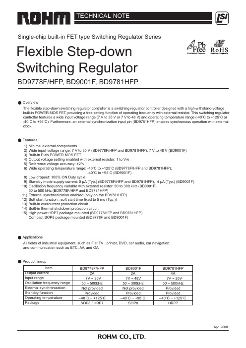
1) Minimal external components 2) Wide input voltage range: 7 V to 35 V (BD9778F/HFP and BD9781HFP), 7 V to 48 V (BD9001F) 3) Built-in P-ch POWER MOS FET 4) Output voltage setting enabled with external resistor: 1 to VIN 5) Reference voltage accuracy: ±2% 6) Wide operating temperature range: -40˚C to +125˚C (BD9778F/HFP and BD9781HFP),
TECHNICAL NOTE
Single-chip built-in FET type Switching Regulator Series
Flexible Step-down Switching Regulator
BD9778F/HFP, BD9001F, BD9781HFP
Overview
The flexible step-down switching regulator controller is a switching regulator controller designed with a high-withstand-voltage built-in POWER MOS FET, providing a free setting function of operating frequency with external resistor. This switching regulator controller features a wide input voltage range (7 V to 35 V or 7 V to 48 V) and operating temperature range (-40˚C to +125˚C or -40˚C to +95˚C). Furthermore, an external synchronization input pin (BD9781HFP) enables synchronous operation with external clock.
K9F1208中文资料

NAND Flash芯片K9F1208资料一 NAND FlaSh和NOR Flash闪存(Flash Memory)由于其具有非易失性、电可擦除性、可重复编程以及高密度、低功耗等特点,被广泛地应用于手机、MP3、数码相机、笔记本电脑等数据存储设备中。
NAND Flash和NOR Flash是目前市场上两种主要的非易失闪存芯片。
与NOR Flash相比,NAND Flash 在容量、功耗、使用寿命等方面的优势使其成为高数据存储密度的理想解决方案。
NOR Flash的传输效率很高,但写入和擦除速度较低;而NAND Flash以容量大、写速度快、芯片面积小、单元密度高、擦除速度快、成本低等特点,在非易失性类存储设备中显现出强劲的市场竞争力。
结构:NOR Flash为并行,NAND Flash为串行。
总线:NOR Flash为分离的地址线和数据线,而NANDFlash为复用的。
尺寸:典型的NAND Flash尺寸为NOR Flash尺寸的1/8。
坏块:NAND器件中的坏块是随机分布的,需要对介质进行初始化扫描以发现坏块,并将坏块标记为不可用。
位交换:NAND Flash中发生的次数要比NOR Flash多,建议使用NAND闪存时,同时使用EDC/ECC算法。
使用方法:NOR Flash是可在芯片内执行(XIP,eXecute In Place),应用程序可以直接在FIash闪存内运行,不必再把代码读到系统RAM 中;而NAND Flash则需I/O接口,因此使用时需要写入驱动程序。
通过以上的分析和比较,NAND Flash更适合于大容量数据存储的嵌入式系统。
本设计选用Samsung公司生产的NAND Flash存储器芯片K9F1208作为存储介质,并应用在基于uPSD3234A增强型8051单片机的嵌入式系统中。
二K9F1208介绍K9F1208是Samsung公司生产的512 Mb(64M×8位)NAND Flash 存储器。
东芝芯片资料
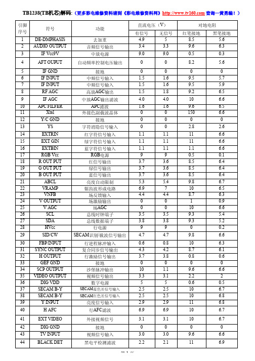
0 900Ω 600Ω 19.5K 15K 13K 19K
LA7833引脚功能
引脚
1 2 3 4 4 6 7
功能
接地端 场输出 自举升压电源端 场激励输入 负反馈输入及相位补偿 电源端 场逆程脉冲输出
直流电压
0V 13.6V 25.5V 0.8V 0.8V 26V 1.4V
纹波滤波电路引脚 第二伴音中频输出 调频直流反馈滤波电路引脚
电压
1.8V 0V 1.3V
+2.5V
+5V 2.45V 2.45V
1V 6.4V 0V 0V 2.3V 1.6V 0V +5V 3.6V 4.3V 0V 8V 8.8V 3.5V 5.6V 3.4V 3.5V
RXIK档对地电阻(黑表笔接地)
场AGC 总线时钟端子 总线数据端子
行电源 SECAM识别/载波信号输出
行逆程脉冲输入 复合同步信号输出 行激励信号输出
接地 沙堡脉冲输出 视频信号输出
数字电源
SECAM蓝色差信号输入 SECAM红色差信号输入
亮度信号输入 行AFC滤波
外接视频信号
接地 视频信Leabharlann 输入黑电平检测滤波直流电压(V)
有信号 4.9
800Ω 0
12.5K
12.8K
6K 13K 13K 13K 12.8K 13.2K
0 12.8K 13K 11.5K
1K 12.5K 12K
0 900Ω 600Ω 12.5K 12.2K 11.5K 12K
红笔接地 R×1K档
800Ω 0
19K
27K
5.5K 20K 20K 18K 28K 28K
MP24833真正中文版

描述MP24833 是 55V,3A白光 LED 驱动器适用于降压,反相升/降压和升压应用。
它具有 3A输出电流在较宽的输入电压范围内具有优异的负载和线性调整。
电流模式能提供快速的瞬态响应和环路稳定性设计。
故障保护包括热关断,逐周期峰值电流限制,开弦保护和输出短路保护。
MP24833 采用模拟和PWM调光复用一个控制引脚。
单独的输入参考接地引脚可以直接使能芯片或者调光控制为正的负功率转换。
MP24833需要最少的标准外部元件和采用SOIC8E 封装。
特点•3A 最大输出电流•独特的升降压操作 (降压-升压模式)•宽输入电压范围:4.5V~55V(降压模式)•0.19Ω 内部功率MOSFET开关•开关频率:200KHz•模拟和PWM调光•0.198V 参考电压•6μA 关断模式•无LED最小数量•稳定低ESR陶瓷输出电容器•逐周期过流保护•热关断保护•开弦保护•输出短路保护•封装: SOIC8E应用•常规 LED 照明•LCD背光板•笔记本电脑•汽车内部照明•便携式多媒体播放器•便携式 GPS 设备For MPS green status, please visit MPS website under Quality Assurance.“MPS” and “The Future of Analog IC Technology” are Registered Trademarks of Monolithic Power Systems, Inc.MP24833A, 55V3白光LED驱动器The Future of Analog IC Technology绝对最大额定值 (1)供应电压 V DD - V SS .............................................. 60V V SW - V SS ......................................-0.3V to V IN + 0.3V V BST .............................................................V SW + 6V V EN/Dim - V INGND ..........................................-0.3Vto+6V V INGND - V SS ............................................-0.3V to 60V 其他引脚 - V SS ….....................................-0.3V to +6V 连续功率耗散(T A= +25°C) (2)SOIC8E..............................................................2.5W 结温……………………....................................150°C 铅温度………………….....................................260°C 贮存温度……………..................-65°C to +150°C推荐的操作条件 (3)供应电压 V DD - V SS ..................................4.5V to 55VJ C热阻 (4) θJA θJCSOIC-8 EP ..............................50 ......10...°C/W备注:1) 超过绝对最大额定值可能会损坏芯片.2) 最大允许功率耗散是一个函数的最大结温T J (MAX), 结到环境热阻 θJA , 和 环境温度 T A . 在任何环境温度的最大允许连续功率耗散计算由P D (MAX) = (T J (MAX)-T A )/θJA . 超过最大允许功耗 会导致过高的模具温度, 同时芯片将进入热关断.对内部热关断电路造成永久性的损坏.3) 芯片不能保证在推荐的工作条件以外的情况下正常工作. 4) 测试是在 JESD51-7, 4-layer PCB.定购信息引脚配置4.5V V IN 55V5) 保证所设计的.典型性能特征性能波形测试在评估板的设计示例部分. V IN = 36V, I LED = 1A, 7个WLEDs 串联, L = 68µH, T A = 25°C, 降压应用,除非另有说明.典型的性能特征(续)性能波形测试在评估板的设计示例部分. V IN = 24V, I LED = 1A, 7个WLEDs 串联, L = 68µH, T A = 25°C, 降压升压应用, 考阅 INGND, 除非另有说明.引脚功能功能方框图图1: 功能框图操作MP24833是一个电流型调节器,误差放大器 (EA) 的输出电压与峰值电感电流成正比。
五通道DVD马达驱动电路A5888 说明书
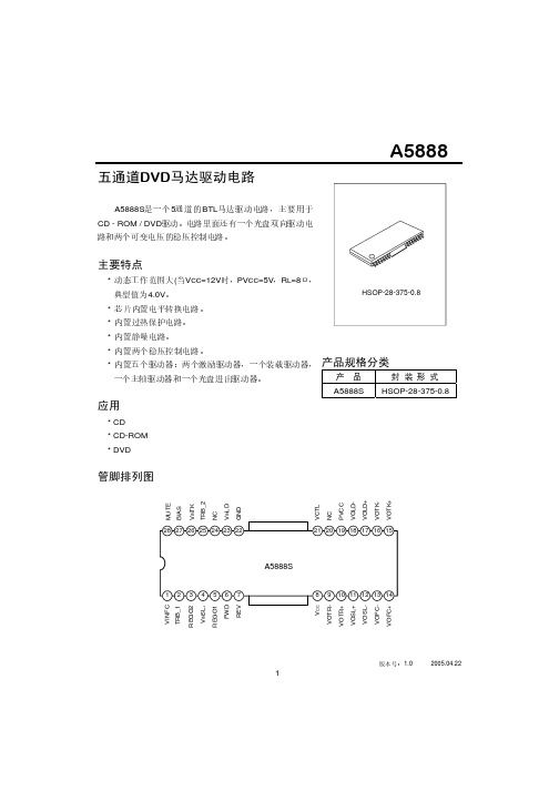
A5888版本号:1.0 2005.04.221五通道DVD 马达驱动电路A5888S 是一个5通道的BTL 马达驱动电路,主要用于CD - ROM / DVD 驱动。
电路里面还有一个光盘双向驱动电路和两个可变电压的稳压控制电路。
主要特点* 动态工作范围大(当V CC =12V 时,PV CC =5V ,R L =8Ω,典型值为4.0V 。
* 芯片内置电平转换电路。
* 内置过热保护电路。
* 内置静噪电路。
* 内置两个稳压控制电路。
* 内置五个驱动器:两个激励驱动器,一个装载驱动器,一个主轴驱动器和一个光盘进出驱动器。
应用* CD * CD-ROM * DVD产品规格分类产 品封 装 形 式A5888S HSOP-28-375-0.8管脚排列图V I N F T R B _R E G O V I N S L R E G O F W R E V C V O T V O T R V O S L V O F V O S V O F C U T ER B _2I N T KCI N L DN DC T LC V C CO L D -O T K -O L D +O T K +I A SA5888版本号:1.0 2005.04.222内部框图极限参数 (Tamb=25°C)参 数 符 号 参 数 范 围单 位 电源电压 V CC ,PV CC 1/213.5 V功率消耗 P D1.7注W工作温度 T opr -35~+85 °C 贮存温度T stg -55~+150 °C注:当安装玻璃纤维底板(面积为70mm x 70mm ,厚度1.6 mm ),T amb >25°C 时,每上升一度便会减少13.6 mW 。
电气参数(除非特别指明,T amb =25°C ,V CC =12.0V ,PV CC = 5V ,BIAS=2.5V ,R L =8Ω/10Ω/20Ω/45Ω)参 数符号测 试 条 件 最小值典型值 最大值 单位 静态电流 I CC-- 30 -- mA激励驱动器 输出失调电压 V oo-50 -- 50 mV最大输出幅度 V OM 10Ω负载 3.6 4.0 -- V电压增益G VV IN =BIAS ±0.2V 22.5 23.524.5 dB(见下页)A5888(接上页)参数符号测试条件最小值典型值最大值单位主轴马达驱动部分输出失调电压V OOFSP -5050mV最大输出幅度V OMSP8Ω负载 -3.5--V 闭环电压增益G VSP V IN=BIAS±0.2V 13.3 15.5 17.5 dB增益极性差异∆G VSP V IN=BIAS±0.2V 0 1 2 dB滑行马达驱动部分输出失调电压V OOFSL -100 0 100 mV最大输出幅度V OMSL20Ω负载 7.59.0--V 闭路电压增益G VSL VIN=BIAS±0.2V 18 20 22 dBSTBY逻辑STBY开启电压V STBY1所有通道关闭 0--0.5V STBY关闭电压V STBY2所有通道开启 2.0----V光盘驱动器输出饱和电压1 V SAT1上管加上下管饱和电压,I L=200mA0.7 1.1 1.5 V正向和反向间的饱和电压差1 ∆V SAT1正向和反向间的饱和电压差1-- -- 0.1 V输出饱和电压2 V SAT2上管加上下管饱和电压,I L=500mA1.0 1.552.2 VVCTR为高时的输出电压增益V VtrH V CTR=2V 7.49.211dB光盘驱动器输入规则输入高电平电压V IH 1.5 - V CC V输入低电平电压V IL-0.3 - 0.5 V输入高电平电压流I IH V FWD=V REV=5V -180 270 µA稳压器输出电压V reg I L = 500mA② 1.5--4.0V 负载不同输出偏差∆V RL I L = 0~500mA③ -50-050mV电源不同输出偏差∆V VCC(V CC=4.5~8V) I L = 500mA -25 0 25 mV①该IC没有设计防辐射功能;②基于8550C PNP的应用;③基于8550D PNP的应用。
D2498中文资料
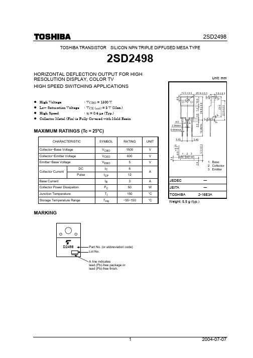
TOSHIBA TRANSISTOR SILICON NPN TRIPLE DIFFUSED MESA TYPE2SD2498HORIZONTAL DEFLECTION OUTPUT FOR HIGH RESOLUTION DISPLAY, COLOR TVHIGH SPEED SWITCHING APPLICATIONSHigh Voltage : V CBO = 1500 VLow Saturation Voltage : V CE(sat) = 5 V (Max.)High Speed : t f= 0.4 µs (Typ.)Collector Metal (Fin) is Fully Covered with Mold ResinMAXIMUM RATINGS (Tc = 25°C)CHARACTERISTIC SYMBOLRATINGUNIT Collector−Base Voltage V CBO1500 V Collector−Emitter Voltage V CEO600 V Emitter−Base Voltage V EBO 5 VDC I C 6Collector CurrentPulse I CP12A Base Current IB 3 A Collector Power Dissipation P C50 W Junction Temperature T j150 °C Storage Temperature Range T stg−55~150 °C MARKING Unit: mmJEDEC ―JEITA ―TOSHIBA 2-16E3AWeight: 5.5 g (typ.)lead (Pb)-free package orlead (Pb)-free finish.D2498ELECTRICAL CHARACTERISTICS (Tc = 25°C)CHARACTERISTIC SYMBOL TEST CONDITION MINTYP. MAX UNIT Collector Cut −off Current I CBO V CB = 1500 V, I E = 0 ― ― 1 mA Emitter Cut −off Current I EBO V EB = 5 V, I C = 0 ― ― 10 µA Collector −Emitter BreakdownVoltageV (BR) CEO I C = 10 mA, I B = 0 600―― Vh FE (1) V CE = 5 V, I C = 1 A 10 ― 30DC Current Gainh FE (2) V CE = 5 V, I C = 4A 5 ― 9 ―Collector −Emitter Saturation VoltageV CE (sat) I C = 4A, I B = 0.8 A ―― 5 VBase −Emitter Saturation VoltageV BE (sat) I C = 4 A, I B = 0.8 A ― 0.9 1.2 V Transition Frequency f T V CE = 10 V, I C = 0.1 A ― 2 ― MHz Collector Output Capacitance C ob V CB = 10 V, I E = 0, f = 1 MHz ― 95 ― pF Storage Time t stg ― 7 10Switching Time (Fig.1)Fall Timet fI CP = 4 A, I B1 (end) = 0.8 A f H = 15.75 kHz― 0.4 0.7µsFig.1 SWITCHING TIME TEST CIRCUIT• The information contained herein is subject to change without notice.• The information contained herein is presented only as a guide for the applications of our products. No responsibility is assumed by TOSHIBA for any infringements of patents or other rights of the third parties which may result from its use. No license is granted by implication or otherwise under any patent or patent rights of TOSHIBA or others. • TOSHIBA is continually working to improve the quality and reliability of its products. Nevertheless, semiconductor devices in general can malfunction or fail due to their inherent electrical sensitivity and vulnerability to physical stress. It is the responsibility of the buyer, when utilizing TOSHIBA products, to comply with the standards of safety in making a safe design for the entire system, and to avoid situations in which a malfunction or failure of such TOSHIBA products could cause loss of human life, bodily injury or damage to property.In developing your designs, please ensure that TOSHIBA products are used within specified operating ranges as set forth in the most recent TOSHIBA products specifications. Also, please keep in mind the precautions and conditions set forth in the “Handling Guide for Semiconductor Devices,” or “TOSHIBA Semiconductor Reliability Handbook” etc.. • The TOSHIBA products listed in this document are intended for usage in general electronics applications (computer, personal equipment, office equipment, measuring equipment, industrial robotics, domestic appliances, etc.). These TOSHIBA products are neither intended nor warranted for usage in equipment that requires extraordinarily high quality and/or reliability or a malfunction or failure of which may cause loss of human life or bodily injury (“Unintended Usage”). Unintended Usage include atomic energy control instruments, airplane or spaceship instruments, transportation instruments, traffic signal instruments, combustion control instruments, medical instruments, all types of safety devices, etc.. Unintended Usage of TOSHIBA products listed in this document shall be made at the customer’s own risk. • TOSHIBA products should not be embedded to the downstream products which are prohibited to be produced and sold, under any law and regulations.030619EAARESTRICTIONS ON PRODUCT USE。
7809中文资料

∆Vo Tj=25°C,Vi=7.5V to 25V
Tj=25°C,Vi=8V to 12V
负载调整率
∆Vo Tj=25°C,Io=5.0mA to 1.5A
Tj=25°C,Io=250mA to 750mA
静态电流
IQ Tj=25°C
静态电流变化率
∆IQ Io=5mA to 1.0A
Vi=8V to 25V
输出电压温漂
∆Vo/∆T Io=5mA
输出噪音电压 纹波抑制比 输入输出电压差 输出阻抗 短路电流 峰值电流
VN f=10Hz to 100kHz,Ta=25°C RR f=120Hz, Vi=8V to 18V Vo Io=1.0A,Tj=25°C Ro f=1kHz Isc Vi=35V,Ta=25°C Ipk Tj=25°C
∆Vo Tj=25°C,Vi=21V to 33V
Tj=25°C,Vi=24V to 30V
负载调整率
∆Vo Tj=25°C,Io=5.0mA to 1.5A
Tj=25°C,Io=250mA to 750mA
输出阻抗
Ro f=1kHz
短路电流
Isc Vi=35V,Ta=25°C
峰值电流
Ipk Tj=25°C
最小值 典型值 最大值 单位 14.4 15.0 15.6 V
14.25 15 15.75 V
11 300 mV
3
150 mV
12 300 mV
4
150 mV
5.2
8
mA
0.5 mA
0.8 mA
-1
mV/°C
峰值电流
Ipk Tj=25°C
最小值 典型值 最大值 单位 9.6 10 10.4 V
8通道8位模_数转换器ADC0808_0809原理及应用

输出编码N的中心可通过以下公式给出:
对于任意输入的输出代码N,它应是以下公式范围描述范围内 的整数:
5功能遥控器PT8A977_978的应用
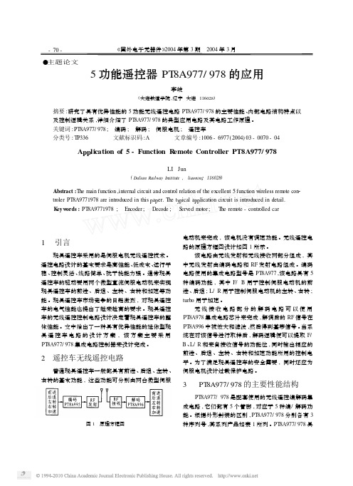
●主题论文5功能遥控器PT 8A977/978的应用李峻(大连铁道学院,辽宁大连116028)摘要:研究了具有优异性能的5功能无线遥控电路PT 8A977/978的主要性能、内部电路结构特点以及控制逻辑关系,详细介绍了PT 8A977/978的典型应用电路及其电路工作原理。
关键词:PT 8A977/978;编码;解码;伺服电机;遥控车分类号:TP336文献标识码:A 文章编号:1006-6977(2004)03-0070-04A pp lication of 5-Function R emote Controller PT8A977/978LI Jun(Dalian Railwa y Institute ,liaonin g 116028)Abstract :T he m ain function ,internal circuit and control relation of the ex cellent 5function w ireless rem ote con 2troler PT 8A9771978are introduced in this p a p er.T he t y p ical a pp lication circuit is introduced detail.K e y w ords :PT 8A9771978;Encoder ;Decode ;S erved m otor ;T he rem ote -controlled car1引言玩具遥控车采用的是伺服电机无线遥控技术。
遥控电路设计的基本要求是高性能、低成本、运行平稳、控制灵活、线路简单、抗干扰能力强。
通常玩具遥控车的驱动要用两个微型直流伺服电动机来实现玩具遥控车的前进、后退、左转、右转和加速等功能。
玩具遥控车市场竞争的日趋激烈,对玩具遥控车的电气性能也提出了越来越高的要求。
玩具遥控车的无线遥控控制电路设计决定着玩具遥控车的整体性能。
HD6433397CP资料
(2021年整理)adc0808中文资料

adc0808中文资料编辑整理:尊敬的读者朋友们:这里是精品文档编辑中心,本文档内容是由我和我的同事精心编辑整理后发布的,发布之前我们对文中内容进行仔细校对,但是难免会有疏漏的地方,但是任然希望(adc0808中文资料)的内容能够给您的工作和学习带来便利。
同时也真诚的希望收到您的建议和反馈,这将是我们进步的源泉,前进的动力。
本文可编辑可修改,如果觉得对您有帮助请收藏以便随时查阅,最后祝您生活愉快业绩进步,以下为adc0808中文资料的全部内容。
11.2。
4 典型的集成ADC芯片为了满足多种需要,目前国内外各半导体器件生产厂家设计并生产出了多种多样的ADC芯片。
仅美国AD公司的ADC产品就有几十个系列、近百种型号之多.从性能上讲,它们有的精度高、速度快,有的则价格低廉.从功能上讲,有的不仅具有A/D转换的基本功能,还包括内部放大器和三态输出锁存器;有的甚至还包括多路开关、采样保持器等,已发展为一个单片的小型数据采集系统。
尽管ADC芯片的品种、型号很多,其内部功能强弱、转换速度快慢、转换精度高低有很大差别,但从用户最关心的外特性看,无论哪种芯片,都必不可少地要包括以下四种基本信号引脚端:模拟信号输入端(单极性或双极性);数字量输出端(并行或串行);转换启动信号输入端;转换结束信号输出端。
除此之外,各种不同型号的芯片可能还会有一些其他各不相同的控制信号端.选用ADC芯片时,除了必须考虑各种技术要求外,通常还需了解芯片以下两方面的特性.(1)数字输出的方式是否有可控三态输出。
有可控三态输出的ADC 芯片允许输出线与微机系统的数据总线直接相连,并在转换结束后利用读数信号RD选通三态门,将转换结果送上总线。
没有可控三态输出(包括内部根本没有输出三态门和虽有三态门、但外部不可控两种情况)的ADC芯片则不允许数据输出线与系统的数据总线直接相连,而必须通过I/O接口与MPU交换信息。
(2)启动转换的控制方式是脉冲控制式还是电平控制式.对脉冲启动转换的ADC芯片,只要在其启动转换引脚上施加一个宽度符合芯片要求的脉冲信号,就能启动转换并自动完成。
Eaton Type 7 9 爆破防护封闭控制商品说明书

9Type 7/9 Hazardous Location StartersType 7/9 Explosion Proof EnclosedControlOther Hazardous Location Controls9.1NEMA Cast Aluminum Enclosed StartersProduct Description . . . . . . . . . . . . . . . . . . . . . . . . . . . . . . . . . . . . . . .V10-T9-2Features . . . . . . . . . . . . . . . . . . . . . . . . . . . . . . . . . . . . . . . . . . . . . . . .V10-T9-2Standards and Certifications . . . . . . . . . . . . . . . . . . . . . . . . . . . . . . . .V10-T9-3Code Definitions . . . . . . . . . . . . . . . . . . . . . . . . . . . . . . . . . . . . . . . . .V10-T9-3Additional Reference . . . . . . . . . . . . . . . . . . . . . . . . . . . . . . . . . . . . . .V10-T9-3Catalog Number Selection . . . . . . . . . . . . . . . . . . . . . . . . . . . . . . . . . .V10-T9-4Cover Control . . . . . . . . . . . . . . . . . . . . . . . . . . . . . . . . . . . . . . . . . . . .V10-T9-5Product SelectionFreedom Full Voltage Non-Combination . . . . . . . . . . . . . . . . . . . . .V10-T9-6Freedom Full Voltage Combination . . . . . . . . . . . . . . . . . . . . . . . . .V10-T9-9Other Hazardous Location Control . . . . . . . . . . . . . . . . . . . . . . . . . . . .V10-T9-12Wiring Diagrams . . . . . . . . . . . . . . . . . . . . . . . . . . . . . . . . . . . . . . . . .V10-T9-13Dimensions . . . . . . . . . . . . . . . . . . . . . . . . . . . . . . . . . . . . . . . . . . . . .V10-T9-1899.1Type 7/9 Hazardous Location StartersNEMA Cast Aluminum Enclosed StartersNEMA Cast Aluminum Enclosed StartersContentsDescription PageNEMA Cast Aluminum Enclosed StartersStandards and Certifications . . . . . . . . . . . . . .V10-T9-3Code Definitions . . . . . . . . . . . . . . . . . . . . . . .V10-T9-3Additional Reference . . . . . . . . . . . . . . . . . . . .V10-T9-3Catalog Number Selection . . . . . . . . . . . . . . . .V10-T9-4Cover Control . . . . . . . . . . . . . . . . . . . . . . . . . .V10-T9-5Freedom Full Voltage Non-Combination . . . . . .V10-T9-6Freedom Full Voltage Combination . . . . . . . . .V10-T9-9Other Hazardous Location Control . . . . . . . . . .V10-T9-12Wiring Diagrams . . . . . . . . . . . . . . . . . . . . . . .V10-T9-13Dimensions . . . . . . . . . . . . . . . . . . . . . . . . . . .V10-T9-18Product DescriptionEaton’s combination andnon-combination hazardouslocation cast aluminum motorstarters are used in areaswhere hazardous materialsare handled or stored. Theseunits provide disconnectingmeans, under voltageprotection, circuit protectionand motor running protection.Features●65,000 AI cUL classified—highest interrupt ratedenclosure in the industry●Copper-free cast aluminum●Precision machine flamepath between box andcover●Bolt-on slotted mountingfeet●Stainless steel blockhinges●Stainless steel, captivequad-lead cover bolts(disengaged in 1-1/2 turns)●External stainless steelbreaker operating handle●Breaker and operatorshafts are stainless steel●Ground lug package andinstallation instructions fortermination of ground wireenclosed●Four point control terminalblock, NEMA 1B with wiremarkers●Breaker operators can belocked in the ON or OFFposition (combinationstarters only)●Four plugged 3/4 in NPSMoutlets drilled and tappedfor control devices●Standard outlets top andbottom●Plugged 1/2 in outlets topand bottom for breather/drain●Components are mountedon a galvanized steelremovable pan●O-ring gasket ensureswatertight integrityStandard Materials●Bodies and covers: copper-free aluminum●Cover bolts: stainless steel●O-ring: neoprene●Hinges: stainless steelFinishes●Bodies and covers:corrosion resistant greyepoxy power coat insideand outside standard toprovide Type 4X99.1Type 7/9 Hazardous Location StartersNEMA Cast Aluminum Enclosed StartersStandards and CertificationsNote: See T ab 17 for additional information on standards and certifications that apply to all enclosed control products.●UL Classified—Standard 886 File #104565●Class I , Groups B, C and D ●Class II , Groups E, F and G ●Class III ●Type 4, 4X, 7 and 9●Zone 1, II B + H2●CSA Certified—StandardC22.2 File #28361●Class I , Groups B, C and D ●Class II , Groups E, F and G ●Class III ●Type 4, 4X, 7 and 9●Zone 1, II B + H2Code DefinitionsClass I locations require thetype of explosion-proofelectrical equipment where, in case of explosion, the hazardous flames would be contained. In Class II or III locations, dust, fibers and flyings are the combustible materials and it is only necessary to keep thesematerials out of the electrical equipment (where an arc may take place) and to maintain safe external temperatures.A brief explanation of the three classifications covering hazardous locations follows:Class I Locations —are those in which flammable gases or vapors are, or may be,present in the air in quantities sufficient to produce explosive or ignitable mixtures.Class I , Div. 1—are those where such hazardousconcentrations of flammable liquids or vapors exist under normal operating conditions.Class I , Div. 2—are those where such hazardousconcentrations of flammable liquids or vapors are handled in closed containers or closed systems.Class II Locations —arethose where the presence of combustible dust presents a fire or explosion hazard.Class II , Div. 1—are those where dust is suspended in the air under normal operating conditions, in quantities sufficient toproduce explosive or ignitable mixtures.Class II , Div. 2—are those where such dust is notnormally in the air, but where deposits of it accumulating on the electrical equipment will interfere with safe dissipation of heat, causing a fire hazard.Class III Locations —are those where easily ignitable fibers or flyings are present but not likely to be suspended in the air in quantities sufficient to produce ignitable mixtures.Class III , Div. 1—are those where ignitable fibers or materials producing combustible flyings are handled, manufactured or used.Class III , Div. 2—are those where easily ignitable fibers are stored or handled (except in process or manufacture).Further refinement created for the purpose of testing and approving electricalequipment divides Class I into four separatedesignations: A, B, C, D and Class II into three separate designations; E, F and G. Underwriters Laboratories test and approve electrical equipment for the following specific groups:Class I , Group A —atmospheres containing acetylene.Class I , Group B —atmospheres containing hydrogen, gases and vapors of equivalent hazard such as manufactured gas.Class I , Group C —atmospheres containing ethyl-ether vapors, ethylene or cyclopropane.Class I , Group D —atmospheres containing gasoline, hexane, naphtha, benzine, butane, propane, alcohol, acetone, benzol, lacquer solvent vapors or natural gas.Class II , Group E —atmospheres containing metal dust, includingaluminum, magnesium and their commercial alloys, and other metals of similarly hazardous characteristics.Class II , Group F —atmospheres containing carbon black, coal or coke dust.Class II , Group G —atmospheres containing flour, starch or grain dusts.Additional ReferenceCover Control . . . . . . . . . . . . . . . . . . . . . . . . . . . . V10-T9-5Wiring Diagrams. . . . . . . . . . . . . . . . . . . . . . . . . . V10-T9-13Dimensions . . . . . . . . . . . . . . . . . . . . . . . . . . . . . V10-T9-18Accessories and Modifications . . . . . . . . . . . . . . T ab 15Renewal Parts . . . . . . . . . . . . . . . . . . . . . . . . . . . T ab 16Technical Data and Specifications . . . . . . . . . . . .T ab 1799.1Type 7/9 Hazardous Location StartersNEMA Cast Aluminum Enclosed StartersCatalog Number SelectionT ype 7/9 Hazardous LocationNotes1For soft starter information see Tab 5.2IT.: If CPT is selected, power supply to be 120V–24 Vdc.3Freedom: When control power transformer modification codes (C1–C11) are used or when starter class includes CPT(that is, ECN07, 24) see table below for system voltage code.4Power supply omitted.5Use for Sizes 0–3, HMCP 600V applications only.Code Primary SecondaryB240/480–220/440 wired for 240V120/60–110/50C240/480–220/440 wired for 480V120/60–110/50D600/60–550/50120/60–110/50E208/60120/60DesignN = Freedom NEMAS = Soft starter 1Class Page05 = Type 7/9 non-combination non-reversing starter V10-T9-606 = Type 7/9 non-combination reversing starter V10-T9-707 = Type 7/9 non-combination starter with CPT V10-T9-822 = Type 7/9 combination non-reversing starter—circuit breakerV10-T9-923 = Type 7/9 combination reversing starter—circuit breakerV10-T9-1024 = Type 7/9 combination starter with CPT—circuit breakerV10-T9-11Modification CodesSee Tab 15NEMA SizeA = Size 000 = Size 01 = Size 12 = Size 23 = Size 34 = Size 45 = Size 5Circuit Breaker RatingsABCDEF= None= 3A= 7A= 15A= 30A= 50AWGXHJK= 70A= 100A/R3C= 100A/T3C= 150A= 250A= 400A56789I= 3A 5= 7A 5= 15A 5= 30A 5= 50A 5= 100A 5Cover ControlNon-rev. starters see TableRev. starters see TableMotor Voltage/Power Supply 23ABCDEQL= 120/60 110/50= 240/60 220/50 Freedom; 230/60 IT.= 480/60 440/50 Freedom; 460/60 IT.= 600/60 550/50= 208/60 Freedom; 200/60 IT.= 24 Vdc 4= 380V/50 HzEC N2216B A C-Enclosure Type6 = Type 7/9—bolted99.1Type 7/9 Hazardous Location StartersNEMA Cast Aluminum Enclosed StartersCover ControlTo order factory installed pilot devices, change the ninth character of the catalog number to the alpha shown in the table below.Example: to order anECN0516CAA with START/STOP pushbuttons and a red pilot light, change the A to a C , that is, ECN0516C C A.Non-Reversing and Reversing Cover ControlDescriptionFactory Installed Flange ControlPosition 9 AlphaNon-Reversing Cover Control No cover mounted pilot devices A START/STOP pushbuttons B With red RUN pilot light C With red RUN/green OFF lights D ON/OFF pushbuttons E With red RUN pilot light F With red RUN/green OFF lights G HAND/OFF/AUTO selector switch H With red RUN pilot light J With red RUN/green OFF lights K START pushbutton L ON pushbutton M OFF pushbutton N Red RUN pilot light P Green OFF pilot light Q Red RUN/green OFF pilot lights R START/STOP selector switch S With red RUN pilot light T With red RUN/green OFF lights U ON/OFF selector switch V With red RUN Pilot Light W With red RUN/green OFF lightsX Reversing Cover Control No cover mounted pilot devices A FOR/REV/STOP pushbuttons B With 2 red pilot lights C With 2 red/1 green pilot lights D UP/STOP/DOWN pushbuttons E With 2 red pilot lights F FOR/OFF/REV selector switch H With 2 red pilot lights J With 2 red/1 green pilot lights K Two red pilot lights P One green pilot light Q Two red/1 green pilot lights R OPEN/OFF/CLOSE selector switch V With 2 red pilot lights W With 2 red/1 green pilot lightsX Cover Control99.1Type 7/9 Hazardous Location StartersNEMA Cast Aluminum Enclosed StartersFreedom Full Voltage Non-CombinationFeatures●Full voltage●Standard interchangeable heater OLR●Optional electronic overload●600V maximumProduct SelectionClass ECN05—T ype 7/9 Non-Combination Non-Reversing StarterNotesStarters do not include heater packs. Select one carton of three heater packs. For heater pack selection, see Tab 15.Starters with electronic overload, see modification codes in Tab 15.1Maximum horsepower rating of starters for 380V 50 Hz applications:NEMASizeMotorVoltageMaximumhpRating 1MagnetCoilVoltageThree-Pole Type7/9 BoltedComponentStarter (Open)Catalog Number Catalog Number 0——120ECN0506AAA AN16BN0AC 2003208ECN0506EAA AN16BN0EC230240ECN0506BAA AN16BN0BC4605480ECN0506CAA AN16BN0CC575600ECN0506DAA AN16BN0DC 1——120ECN0516AAA AN16DN0AB 2007-1/2208ECN0516EAA AN16DN0EB230240ECN0516BAA AN16DN0BB46010480ECN0516CAA AN16DN0CB575600ECN0516DAA AN16DN0DB 2——120ECN0526AAA AN16GN0AB 20010208ECN0526EAA AN16GN0EB23015240ECN0526BAA AN16GN0BB46025480ECN0526CAA AN16GN0CB575600ECN0526DAA AN16GN0DB 3——120ECN0536AAA AN16KN0A 20025208ECN0536EAA AN16KN0E23030240ECN0536BAA AN16KN0B46050480ECN0536CAA AN16KN0C575600ECN0536DAA AN16KN0D 4——120ECN0546AAA AN16NN0A 20040208ECN0546EAA AN16NN0E23050240ECN0546BAA AN16NN0B460100480ECN0546CAA AN16NN0C575600ECN0546DAA AN16NN0D 5——120ECN0556AAA AN16SN0AB 20075208ECN0556EAA AN16SN0EB230100240ECN0556BAA AN16SN0BB460200480ECN0556CAA AN16SN0CB575600ECN0556DAA AN16SN0DBNEMA Size000123456 Horsepower1-1/251025507515030099.1Type 7/9 Hazardous Location StartersNEMA Cast Aluminum Enclosed StartersClass ECN06—T ype 7/9 Non-Combination Reversing StarterNotesStarters do not include heater packs . Select one carton of three heater packs. For heater pack selection, see Tab 15.Starters with electronic overload , see modification codes in Tab 15.1Maximum horsepower rating of starters for 380V 50 Hz applications:NEMA Size Motor Voltage Maximum hpRating 1Magnet Coil Voltage Three-Pole Type 7/9 Bolted Component Starter (Open)Catalog Number Catalog Number 0——120ECN0606AAA AN56BN0AC 2003208ECN0606EAA AN56BN0EC 230240ECN0606BAA AN56BN0BC 4605480ECN0606CAA AN56BN0CC 575600ECN0606DAA AN56BN0DC 1——120ECN0616AAA AN56DN0AB 2007-1/2208ECN0616EAA AN56DN0EB 230240ECN0616BAA AN56DN0BB 46010480ECN0616CAA AN56DN0CB 575600ECN0616DAA AN56DN0DB 2——120ECN0626AAA AN56GN0AB 20010208ECN0626EAA AN56GN0EB 23015240ECN0626BAA AN56GN0BB 46025480ECN0626CAA AN56GN0CB 575600ECN0626DAA AN56GN0DB 3——120ECN0636AAA AN56KN0A 20025208ECN0636EAA AN56KN0E 23030240ECN0636BAA AN56KN0B 46050480ECN0636CAA AN56KN0C 575600ECN0636DAAAN56KN0DNEMA Size000123456Horsepower1-1/251025507515030099.1Type 7/9 Hazardous Location StartersNEMA Cast Aluminum Enclosed StartersClass ECN07—T ype 7/9 Non-Combination Non-Reversing Starter with CPTNotesStarters do not include heater packs. Select one carton of three heater packs. For heater pack selection, see Tab 15.Starters with electronic overload, see modification codes in Tab 15.1For other control power transformer primary and/or secondary voltage options, see Tab 2.2Maximum horsepower rating of starters for 380V 50 Hz applications:NEMASizePrimaryVoltage 1MaximumhpRating 2MagnetCoilVoltageThree-Pole Type7/9 BoltedComponentStarter (Open)Catalog Number Catalog Number 02083120ECN0706EAA AN16BN0AC 240ECN0706BAA4805ECN0706CAA600ECN0706DAA12087-1/2120ECN0716EAA AN16DN0AB 240ECN0716BAA48010ECN0716CAA600ECN0716DAA220810120ECN0726EAA AN16GN0AB 24015ECN0726BAA48025ECN0726CAA600ECN0726DAA320825120ECN0736EAA AN16KN0A 24030ECN0736BAA48050ECN0736CAA600ECN0736DAA420840120ECN0746EAA AN16NN0A 24050ECN0746BAA480100ECN0746CAA600ECN0746DAA520875120ECN0756EAA AN16SN0AB 240100ECN0756BAA480200ECN0756CAA600ECN0756DAANEMA Size000123456 Horsepower1-1/251025507515030099.1Type 7/9 Hazardous Location StartersNEMA Cast Aluminum Enclosed StartersFreedom Full Voltage CombinationFeatures●Full voltage●Standard interchangeable heater OLR ●Optional electronic overload ●600V maximumProduct SelectionECN22—T ype 7/9 Combination Non-Reversing Starter—Circuit BreakerNotesStarters do not include heater packs . Select one carton of three heater packs. For heater pack selection, see Tab 15.Starters with electronic overload , see modification codes in Tab 15.1Starters with 120V coil (for separate control) are available. To order, substitute the letter A for the eighth character of the listed catalog number.NEMA Size Motor Voltage Maximum hp Rating Magnet CoilVoltage 1Circuit Breaker Size Three-Pole Type 7/9 BoltedComponent Starter (Open)Catalog Number Catalog Number 020012087A ECN2206EAC AN16BN0EC315A ECN2206EAD 23012407A ECN2206BAC AN16BN0BC 315A ECN2206BAD 46014803A ECN2206CAB AN16BN0CC 37A ECN2206CAC 515A ECN2206CAD 57516003A ECN2206DA5AN16BN0DC 37A ECN2206DA6515A ECN2206DA7120012087A ECN2216EAC AN16DN0EB 315A ECN2216EAD 530A ECN2216EAE 7-1/250A ECN2216EAF 23012407A ECN2216BAC AN16DN0BB 315A ECN2216BAD 530A ECN2216BAE 7-1/250A ECN2216BAF 46014803A ECN2216CZB AN16DN0CB 37A ECN2216CAC 515A ECN2216CAD 1030A ECN2216CAE 57516003A ECN2216DA5AN16DN0DB 37A ECN2216DA6515A ECN2216DA71030A ECN2216DA822001020850A ECN2226EAF AN16GN0EB 2301024050A ECN2226BAF AN16GN0BB 1570A ECN2226BAW 4602548050A ECN2226CAF AN16GN0CB 5751560030A ECN2226DA8AN16GN0DB 2550A ECN2226DA9320020208100AECN2236EAG AN16KN0E 25ECN2236EAG 23025240100AECN2236BAG AN16KN0B 30ECN2236BAG 46050480100A ECN2236CAG AN16KN0C 5753060050A ECN2236DA9AN16KN0D 50100A ECN2236DAI 420040208150AECN2246EAH AN16NN0E 23050240ECN2246BAH AN16NN0B 460100480ECN2246CAH AN16NN0C 575600ECN2246DAHAN16NN0D99.1Type 7/9 Hazardous Location StartersNEMA Cast Aluminum Enclosed StartersECN23—T ype 7/9 Combination Reversing Starter—Circuit BreakerNotesStarters do not include heater packs. Select one carton of three heater packs. For heater pack selection, see Tab 15.Starters with electronic overload, see modification codes in Tab 15.1Starters with 120V coil (for separate control) are available. To order, substitute the letter A for the eighth character of the listed catalog number.NEMASizeMotorVoltageMaximumhpRatingMagnetCoilVoltage 1CircuitBreakerSizeThree-Pole Type7/9 BoltedComponentStarter (Open)Catalog Number Catalog Number 020012087A ECN2306EAC AN56BN0EC315A ECN2306EAD23012407A ECN2306BAC AN56BN0BC315A ECN2306BAD46014803A ECN2306CAB AN56BN0CC37A ECN2306CAC515A ECN2306CAD57516003A ECN2306DA5AN56BN0DC37A ECN2306DA6515A ECN2306DA7120012087A ECN2316EAC AN56DN0EB315A ECN2316EAD530A ECN2316EAE7-1/250A ECN2316EAF23012407A ECN2316BAC AN56DN0BB315A ECN2316BAD530A ECN2316BAE7-1/250A ECN2316BAF46014803A ECN2316CAB AN56DN0CB37A ECN2316CAC515A ECN2316CAD1030A ECN2316CAE57516003A ECN2316DA5AN56DN0DB37A ECN2316DA6515A ECN2316DA71030A ECN2316DA822001020850A ECN2326EAF AN56GN0EB 2301024050A ECN2326BAF AN56GN0BB1570A ECN2326BAW4602548050A ECN2326CAF AN56GN0CB5751560030A ECN2326DA8AN56GN0DB2550A ECN2326DA9320020208100A ECN2336EAG AN56KN0E25ECN2336EAG23025240100A ECN2336BAG AN56KN0B30ECN2336BAG46050480100A ECN2336CAG AN56KN0C5753060050A ECN2336DA9AN56KN0D50100A ECN2336DAI9NEMA Cast Aluminum Enclosed StartersECN24—T ype 7/9 Combination Non-Reversing Starter with CPT—Circuit BreakerNotesStarters do not include heater packs . Select one carton of three heater packs. For heater pack selection, see Tab 15.Starters with electronic overload , see modification codes in Tab 15.1For other control power transformer primary and/or secondary voltage options, see Tab 2.NEMA Size Primary Voltage 1Maximum hp Rating Magnet Coil Voltage Circuit Breaker Size Three-Pole NEMA 7/9 Bolted Component Starter (Open)Catalog Number Catalog Number 020011207A ECN2406EAC AN16BN0AC315AECN2406EAD 23011207A ECN2406BAC AN16BN0AC315AECN2406BAD 46011203A ECN2406CAB AN16BN0AC37A ECN2406CAC 515AECN2406CAD 57511203A ECN2406DA5AN16BN0AC37A ECN2406DA6515AECN2406DA7120011207A ECN2416EAC AN16DN0AB315A ECN2416EAD 530A ECN2416EAE 7-1/250AECN2416EAF 23011207A ECN2416BAC AN16DN0AB315A ECN2416BAD 530A ECN2416BAE 7-1/250AECN2416BAF 46011203A ECN2416CAB AN16DN0AB37A ECN2416CAC 515A ECN2416CAD 1030AECN2416CAE 57511203A ECN2416DA5AN16DN0AB37A ECN2416DA6515A ECN2416DA71030AECN2416DA822001012050A ECN2426EAF AN16GN0AB 2301012050A ECN2426BAF AN16GN0AB1570AECN2426BAW 4602512050A ECN2426CAF AN16GN0AB 5751512030A ECN2426DA8AN16GN0AB2550AECN2426DA9320020120100A ECN2436EAG AN16KN0A25ECN2436EAG23025120100A ECN2436BAG AN16KN0A30ECN2436BAG46050120100A ECN2436CAG AN16KN0A 5753012050A ECN2436DA9AN16KN0A50100AECN2436DAI 420040120150A ECN2446EAH AN16NN0A23050ECN2446BAH 460100ECN2446CAH 575ECN2446DAHOther Hazardous Location Control Product DescriptionBesides Freedom starters, Eaton offers Type 7/9 cast aluminum enclosures for solid-state reduced voltage starters and lighting contactors.Freedom StartersFor information on hazardous location versions, please consult your Eaton representative.Solid-State Reduced VoltageStartersType 7/9 versions are listed inT ab 5.The IT. soft starters aredesigned to be the smallest,most compact soft starterson the market today. Thebuilt-in overload (ranges from0.25 to 1000A) and runbypass contactor (greatlyreducing the amount of heatgenerated) make installationand setup quick and easy.With this small size and lowheat dissipation it can easilyfit in the place of existing softstarters, Wye-Delta startersor across-the-line starterswhere others cannot. Tomake the retrofit moreflexible, we also offer softstarters as open componentsor as a completed kit on aback panel for easy and quickinstallation into your existingenclosure.Lighting ContactorsType 7/9 versions are listed inT ab 4.99NEMA Cast Aluminum Enclosed StartersWiring DiagramsFreedom Non-Reversing Starter—Single-Phase Non-CombinationFreedom Non-Reversing Starter—CombinationFreedom Reversing Starter—Non-CombinationFreedom Reversing Starter—Combination9NEMA Cast Aluminum Enclosed StartersNon-Reversing Cover ControlT ype 1 C400GK Control OptionsC400T Control OptionsReversing Cover ControlT ype 1 C400GR Control OptionsC400T Control Options9S801+/S811+ Wiring Diagram9NEMA Cast Aluminum Enclosed StartersS801+/S811+ with External 120 Vac Control9DimensionsApproximate Dimensions in InchesNEMA Size FreedomFreedom Full Voltage Non-Reversing StartersReduced Voltage Solid-StateS801+/S811+ Intelligent T echnologies Solid-State Soft StartersS752 Intelligent T echnologies Solid-State Soft StartersRough OutsideDimensionsNon-CombinationSizesStandardConduitCombinationSizesStandardConduit 17 x 140, 1, 21-1/2——28 x 14320, 1, 21-1/232 x 1842-1/23246 x 16534, 53Rough OutsideDimensions Non-CombinationStandardConduit CombinationStandardConduit 17 x 1466A1-1/2——28 x 14135A266A232 x 18——135A2-1/246 x 16304A3304A3Rough OutsideDimensions Non-CombinationStandardConduit CombinationStandardConduit 18 x 1550A1-1/2——28 x 14——50A1-1/29NEMA Cast Aluminum Enclosed StartersApproximate Dimensions in Inches (mm)T ype 7/9 Freedom StartersDimensions A B C D E Height 27.63 (701.8)31.63 (803.4)46.00 (1168.4)16.63 (422.4)17.50 (444.5)Width 14.13 (358.9)18.13 (460.5)26.19 (665.2)14.13 (358.9)15.10 (383.5)Depth11.38 (289.1)12.19 (309.6)14.94 (379.5)9.50 (241.3)10.50 (266.7)Weight in Lbs (kg)125 (57)195 (89)500 (227)80 (36)95 (43)I.D. Height2428371112I.D. Width101417910。
成都华微电子 HWD977 模数转换器 参数手册
HWD977 C S M T模数转换器HWD977参数手册模数转换器1. 概述华微公司HWD977全仿国外AD 公司AD977产品。
华微公司推出的军品级HWD977是工作在5V单电源电压下的高速低功耗16位A/D 转换器。
其中包括一个逐次逼近开关电容ADC、一个内部2.5V参考电压源和一个高速串行接口。
ADC通过校准使所有线性误差最小化。
模拟输入范围为标准工业范围:±10V。
HWD977对信噪比、总谐波失真等交流参数以及失调、增益、线性等参数进行了全面测试。
2. 产品特点HWD977是建立在开关电容基础上的(100KSPS吞吐率)16位ADC。
HWD977工作在5V单电源下,最大功耗仅有100mW。
HWD977通过了校准,并对信噪比、总谐波失真以及失调、增益、线性等参数进行了全面测试。
HWD977提供了一个包含精准ADC、参考电压、片上时钟在内的高度集成的解决方案。
3. 功能框图图1 功能框图4. 引脚信息4.1 引脚排列图图2 HWD977引脚排列图4.2 引脚描述表1 引脚描述5. 绝对最大额定值及推荐工作范围5.1绝对最大额定值模拟输入(R1IN,R2IN,R3IN)............................................................±25V CAP .........................................................+V ANA +0.3V到AGND2-0.3V DGND,AGND1,AGND2...............................................................±0.3V V ANA (7V)V DIG到V ANA...........................................................................±7V V DIG (7V)数字输入………………………………………………………-0.3V到VDIG+0.3V 存储温度范围…………………………………………………………-65℃到+150℃引脚温度范围……………………………………………………………………260℃5.2推荐工作范围数字电源电压(V DIG)…………………………………………………………5.0V 模拟电源电压(V ANA)…………………………………………………………5.0V 工作温度(T A)………………………………………………………-55℃~+125℃注意1:如器件在上述所列“绝对最大额定值”下工作,可能对该器件造成永久性损坏。
FESTO双动力吸爪HGP产品目录说明书

Parallel grippers HGP, with protective dust cap2d Internet: /catalogue/...Subject to change – 2022/10Parallel grippers HGP , with protective dust capKey featuresAt a glance• Double-acting piston drive• With protective dust cap for use in dusty environments (degree of protection IP54)• Self-centring• Variable gripping action:– External/internal gripping• High gripping force and compact size• Max. repetition accuracy • Internal fixed flow control • Versatile thanks to externally adaptable gripper fingers• Wide range of adaptation options on the drives• Sensor technology:– Adaptable proximity switches for the small grippers– Integrated proximity switches for the medium and large gripper sizesH- -NoteEngineering software Gripper selection a Mounting options for external gripper fingers (customer-specific)[1] Parallel gripper[2] External gripper fingers [3] Mounting screws [4]Centring pins2314H- -NoteThese grippers should always be used with exhaust air flow control. They are not suitable for the follow-ing or similar applications:• Machining•Aggressive media•Grinding dust• Welding spatter32022/10 – Subject to changed Internet: /catalogue/...Parallel grippers HGP , with protective dust capPeripherals overview and type codesPeripherals overviewSystem product for handling and assembly technology123Type codesParallel grippers HGP, with protective dust cap Data sheetFunction-N- Size16, 25 mm -T- Stroke10, 14 mm -É-1)Applies to unthrottled operation2)Under constant exposure to operating conditions, end-position drift occurs in the direction of movement of the gripper jaws, at 100 consecutive strokes-H- Note: This product conforms to ISO 1179-1 and ISO 228-1.1)Corrosion resistance class CRC 1 to Festo standard FN 940070Low corrosion stress. Dry indoor application or transport and storage protection. Also applies to parts behind covers, in the non-visible interior area, and parts which are covered in the application (e.g. drive trunnions).4d Internet: /catalogue/...Subject to change – 2022/1052022/10 – Subject to changed Internet: /catalogue/...Parallel grippers HGP , with protective dust capData sheetMaterials Sectional viewGripping force [N] at 6 barCharacteristic load values per gripper jawThe indicated permissible forces and torques apply to a single gripper jaw. The indicated values include the lever arm, additional weight forces caused by the workpiece or external gripper fingers, as well as forces which occur during movement. The zero coordinate line (gripper jaw guide) must be taken intoconsideration when calculating torques.6d Internet: /catalogue/...Subject to change – 2022/10Parallel grippers HGP , with protective dust capData sheetMass moments of inertia [kgm 2x10⁻⁴]Mass moment of inertia [kgm 2x10⁻⁴] for parallel grippers in relation to the centralaxis, without external gripper fingers, without load.Opening and closing times [ms] at 6 bar Without external gripper fingersWith external gripper fingersThe indicated opening and closing times [ms] have been measured at roomtemperature and 6 bar operating pressure without additional gripper fingers. The grippers must be throttled for larger masses [g]. Opening and closing timesmust then be adjusted accordingly.72022/10 – Subject to changed Internet: /catalogue/...Parallel grippers HGP , with protective dust capData sheetGripping force F H per gripper jaw as a function of operating pressure and lever arm xExternal and internal gripping (closing and opening)The gripping forces as a function of operating pressure and lever arm (distance from the zero co-ordinate line shown above to the pressure point at which the fingers grip the workpiece) can be determined for the various sizes using the following graphs.HGP-16-...HGP-25-...ClosingOpeningClosing OpeningGripping force F H per gripper jaw at 6 bar as a function of lever arm x and eccentricity yExternal and internal gripping (closing and opening)The gripping forces at 6 bar as a function of eccentric application of force (distance from the zero co-ordinate line shown above to the pressure point at which the fingers grip the workpiece) and the maximum permissible off-centre point at which force is applied can be determined for the various sizes using the following graphs.Calculation example Assuming:HGP-16-A-B-SSK Lever arm x = 20 mm Eccentricity y = 22 mm Required:Gripping force at 6 barProcedure:• Determine the intersection xybetween lever arm x and eccentricity y in the graph for HGP-16-...• Draw an arc (with centre at origin) through intersection xy• Determine the intersection between the arc and X-axis• Read the gripping force Result:gripping force = approx. 66 NClosing OpeningHGP-16-...HGP-25-...Closing OpeningClosing OpeningParallel grippers HGP, with protective dust capData sheet1)Tolerance for centring hole: ±0.022)Tolerance for centring hole: –0.05-H- Note: This product conforms to ISO 1179-1 and ISO 228-1.8d Internet: /catalogue/...Subject to change – 2022/10Parallel grippers HGP, with protective dust cap AccessoriesBondableMaterial:Wrought aluminium alloyH2B1+0.05/-0.1-0.13.1 6.43.1 6.41)Packaging unit9 2022/10 – Subject to change d Internet: /catalogue/...Parallel grippers HGP, with protective dust capAccessories10d Internet: /catalogue/...Subject to change – 2022/10Festo - Your Partner in AutomationConnect with us/socialmedia 1Festo Inc.2Festo Pneumatic 3Festo Corporation 4Regional Service Center 5300 Explorer DriveMississauga, ON L4W 5G4CanadaAv. Ceylán 3,Col. Tequesquináhuac 54020 Tlalnepantla, Estado de México1377 Motor Parkway Suite 310Islandia, NY 117497777 Columbia Road Mason, OH 45040Festo Customer Interaction CenterTel:187****3786Fax:187****3786Email:*****************************Multinational Contact Center 01 800 337 8669***********************Festo Customer Interaction Center180****3786180****3786*****************************S u b j e c t t o c h a n g e。
芯片说明书:Diodes Incorporated 74AHC164 8位串行输入并行输出移位寄存器

8-BIT PARALLEL-OUT SERIAL SHIFT REGISTERSDescriptionThe 74AHC164 is a serial input 8-bit edge-triggered shift register that has outputs from each of eight stages.SERIAL DATA INPUT PINSThe serial input data is entered at pin SDA or pin SDB as these are logically ANDED. Either input could be used as an active HIGH enable with data entry on the other pin. If a single input is desired, the pins can be tied together or the unused input can be tied HIGH.DATA ENTRYData is shifted into Q0 from the serial input pins on each LOW to HIGH transition of the CP pin. Also during the CP edge the data is transferred from each Qn to Qn+1. The serial data on pins DSA and DSB must be stable before and after the CP rising edge to meet the set-up and hold timing requirements.RESETWhen asserted LOW the Master Reset (MR) pin sets all Qn to LOW. This action does not depend on the condition of serial input or clock pins. The MR must be asserted HIGH for a recovery time before the next CP positive edge pulse.Features∙Wide Supply Voltage Range from 2.0V to 5.5V∙Sinks or Sources 8mA at V CC = 4.5V∙CMOS Low Power Consumption∙Schmitt Trigger Action at All Inputs∙ESD Protection Exceeds JESD 22▪200-V Machine Model (A115)▪2000-V Human Body Model (A114)▪Exceeds 1000-V Charged Device Model (C101)∙Range of Package Options SO-14 and TSSOP-14∙Totally Lead-Free & Fully RoHS Compliant (Notes 1 & 2)∙Halogen and Antimony Free. “Green” Device (Note 3)Pin AssignmentsDSAQ0DSBQ3Q7Q5Q6MRVcc(Top View)SO-14 / TSSOP-14 / PDIP-14GNDQ2CPQ4Q1Applications∙General Purpose Logic∙Wide Array of Products Such as:▪PCs, Networking, Notebooks, Netbooks▪Computer Peripherals, Hard Drives, CD/DVD ROMs ▪TVs, DVDs, DVRs, Set-Top BoxesNotes: 1. No purposely added lead. Fully EU Directive 2002/95/EC (RoHS) & 2011/65/EU (RoHS 2) compliant.2. See /quality/lead_free.html for more information about Diodes Incorporated’s definitions of Halogen- and Antimony-free, "Green"and Lead-free.3. Halogen- and Antimony-free "Green” products are defined as those which contain <900ppm bromine, <900ppm chlorine (<1500ppm total Br + Cl) and<1000ppm antimony compounds.Device ordering information is on page 7Pin DescriptionsFunction Table (Note 4)Note:4. Signals asserted on DSA and DSB must be in place longer than Tsu (set up time) before CP occurs and remain in place Thold (hold time) after CP.Logic DiagramMRTiming DiagramReset All Q=0Reset All Q=0Notes: 5. All Q values are reset to LOW when MR goes low. MR is asynchronous and overrides all other signals.6. Serial data supplied at DSA and DSB is ANDED and transferred to Q0 on positive edge of CP.Absolute Maximum Ratings (Note 7) (T A = +25°C, unless otherwise specified.)Notes: 7. Stresses beyond the absolute maximum may result in immediate failure or reduced reliability. These are stress values and device operation shouldbe within recommend values.8. Input Voltage cannot exceed Vcc to the extent the Maximum clamp current is exceeded.Recommended Operating Conditions (Note 9) (T A = +25°C, unless otherwise specified.)Note: 9. Unused inputs should be held at V CC or Ground.Operating Characteristics(T A = +25°C, unless otherwise specified.)Parameter Measurement InformationFrom OutputC LUnder TestCCCC Pulse Duration and Recovery TimeVoltage WaveformSet-up and Hold TimesV l0 VV OHV OLV OHV OLVoltage WaveformPropagation Delay TimesInverting and Non Inverting OutputsNotes: A. Includes test lead and test apparatus capacitance.B. All pulses are supplied at pulse repetition rate ≤10 Hz.C. Inputs are measured separately one transition per measurement.D. t PLH and t PHL are the same as t PD.Figure 1 Load Circuit and Voltage WaveformsOrdering Information74AHC 164XXX -13Function -13:Packing Logic Device 74:Logic Prefix AHC :2.0V to 5.5V Family164:8-Bit Serial InParallel Out Tape &Reel13"Package S14:SO-14T14:TSSOP-14Shift RegisterD 14:PDIP -14Marking Information(1) SO-14, TSSOP-14, PDIP-14Package Outline Dimensions (All dimensions in mm.)Please see AP02002 at /datasheets/ap02002.pdf for the latest version.Package Type: SO-14Package Type: TSSOP-14Package Type: PDIP-14cDetail “A”Pin# 1 Detail ‘A’Suggested Pad LayoutPlease see AP02001 at /datasheets/ap02001.pdf for the latest version.Package Type: SO-14Package Type: TSSOP-14X C 1XC 111 of 11 August 2015 © Diodes Incorporated74AHC164Document number: DS36281 Rev. 2 - 2。
- 1、下载文档前请自行甄别文档内容的完整性,平台不提供额外的编辑、内容补充、找答案等附加服务。
- 2、"仅部分预览"的文档,不可在线预览部分如存在完整性等问题,可反馈申请退款(可完整预览的文档不适用该条件!)。
- 3、如文档侵犯您的权益,请联系客服反馈,我们会尽快为您处理(人工客服工作时间:9:00-18:30)。
Notes
No technical content pages of this document may be reproduced in any form or transmitted by any means without prior permission of ROHM CO.,LTD. The contents described herein are subject to change without notice. The specifications for the product described in this document are for reference only. Upon actual use, therefore, please request that specifications to be separately delivered. Application circuit diagrams and circuit constants contained herein are shown as examples of standard use and operation. Please pay careful attention to the peripheral conditions when designing circuits and deciding upon circuit constants in the set. Any data, including, but not limited to application circuit diagrams information, described herein are intended only as illustrations of such devices and not as the specifications for such devices. ROHM CO.,LTD. disclaims any warranty that any use of such devices shall be free from infringement of any third party's intellectual property rights or other proprietary rights, and further, assumes no liability of whatsoever nature in the event of any such infringement, or arising from or connected with or related to the use of such devices. Upon the sale of any such devices, other than for buyer's right to use such devices itself, resell or otherwise dispose of the same, no express or implied right or license to practice or commercially exploit any intellectual property rights or other proprietary rights owned or controlled by ROHM CO., LTD. is granted to any such buyer. Products listed in this document are no antiradiation design.
TEL : +33(0)1 56 97 30 60 FAX : +33(0) 1 56 97 30 80 TEL : +852(2)740-6262 TEL : +86(21)6279-2727 TEL : +86(411)8230-8549 TEL : +86(10)8525-2483 TEL : +866(2)2500-6956 TEL : +82(2)8182-700 TEL : +65-6332-2322 TEL : +60(3)7958-8355 TEL : +63(2)807-6872 TEL : +66(2)254-4890 FAX : +852(2)375-8971 FAX : +86(21)6247-2066 FAX : +86(411)8230-8537 FAX : +86(10)8525-2489 FAX : +866(2)2503-2869 FAX : +82(2)8182-715 FAX : +65-6332-5662 FAX : +60(3)7958-8377 FAX : +63(2)809-1422 FAX : +66(2)256-6334
Appendix1-Rev1.1
Contact us
Attached-1
Thank you for your accessing to ROHM product informations. More detail product informations and catalogs are available, please contact your nearest sales office.
United Kingdom / London TEL : +44(1)908-282-666 France / Paris China / Hong Kong Shanghai Dilian Beijing Taiwan / Taipei Korea / Seoul Singapore Malaysia / Kuala Lumpur Philippines /The products listed in this document are designed to be used with ordinary electronic equipment or devices (such as audio visual equipment, office-automation equipment, communications devices, electrical appliances and electronic toys). Should you intend to use these products with equipment or devices which require an extremely high level of reliability and the malfunction of with would directly endanger human life (such as medical instruments, transportation equipment, aerospace machinery, nuclear-reactor controllers, fuel controllers and other safety devices), please be sure to consult with our sales representative in advance. About Export Control Order in Japan Products described herein are the objects of controlled goods in Annex 1 (Item 16) of Export Trade Control Order in Japan. In case of export from Japan, please confirm if it applies to "objective" criteria or an "informed" (by MITI clause) on the basis of "catch all controls for Non-Proliferation of Weapons of Mass Destruction.
Japan / (Internal Sales)
Tokyo Yokohama Nagoya Kyoto 2-1-1, Yaesu, Chuo-ku, Tokyo 104-0082 TEL : +81(3)5203-0321 FAX : +81(3)5203-0300 2-4-8, Shin Yokohama, Kohoku-ku, Yokohama, Kanagawa 222-8575 TEL : +81(45)476-2131 FAX : +81(45)476-2128 Dainagayo Building 9F 3-28-12, Meieki, Nakamura-ku, Nagoya,Aichi 450-0002 TEL : +81(52)581-8521 FAX : +81(52)561-2173 579-32 Higashi Shiokouji-cho, Karasuma Nishi-iru, Shiokoujidori, Shimogyo-ku, Kyoto 600-8216 TEL : +81(75)311-2121 FAX : +81(75)314-6559 TEL : +81(45)476-9270 FAX : +81(045)476-9271
Please contact our sales offices for details ;
U.S.A / San Diego Atlanta Dallas Germany / Dusseldorf TEL : +1(858)625-3630 TEL : +1(770)754-5972 TEL : +1(972)312-8818 TEL : +49(2154)9210 FAX : +1(858)625-3670 FAX : +1(770)754-0691 FAX : +1(972)312-0330 FAX : +49(2154)921400 FAX : +44(1)908-282-528
