MT2011中文资料
MT146.1—2011树脂锚杆第一部分:锚固剂

MT 146.1—2011树脂锚杆第1部分:锚固剂1 范围MT146的本部分规定了树脂锚杆锚固剂(以下简称锚固剂)的产品分类、技术要求、试验方法、检验规则、标志、包装、运输与贮存。
本部分适用于矿山井巷支护用的锚固剂。
井筒装备的安装、基础锚固等工程所需的锚固剂也可参照执行。
3 术语和定义下列术语和定义适用于MT146的本部分。
3.1树脂锚杆 resin anchor bolts以树脂锚固剂配以各种材质杆体及托盘、螺母等构件组成的锚杆。
3。
2树脂锚固剂 resins and capsules起粘结锚固作用的材料称锚固剂。
树脂锚固剂由树脂胶泥与固化剂两部分分隔包装成卷形,混合后能使杆体与被锚固体煤、岩粘结在一起。
3。
3树脂胶泥 resin putty ,resin mastic由树脂、填料和化学助剂组成的胶泥状材料。
3。
4固化剂 catalyst与树脂胶泥混合后,能立即引起化学反应,使树脂胶泥凝结成固体的材料.3。
5凝胶时间 gel time从树脂胶泥与固化剂混合起,到胶泥开始变稠、温度开始上升时的时间.3.6等待安装时间 setting time安装锚杆时,搅拌停止后到可以上托盘的时间.3.7树脂胶泥稠度 viscosity of resin mastic表示树脂胶泥的软硬程度,以试锥1min沉入树脂胶泥的深度(mm)来表示。
3.8抗拔力anti—pulling capacity在规定锚固长度条件下,锚固剂与杆体锚固后,拉拔试验时锚固剂所能承受的极限载荷。
3。
9锚固力 anchor capacity整根锚固剂与配套杆体锚固后,拉拔试验时锚固剂所能承受的极限载荷。
4 产品分类4.1 分类产品按凝胶时间不同进行分类,见表1。
表 1 产品分类M慢速〉180——注1:在(22±1)℃环境温度条件下测定.注2:搅拌应在锚固剂凝胶之前完成.4.2 规格产品应符合表2规定。
表 2 产品规格锚固剂直径352823 mm锚固剂长度30~5030~10030~100 cm推荐适用钻孔直径40~4432~3627~30 mm注:用户特殊需要时,可生产其他规格的锚固剂;锚固剂长度由供需双方商定。
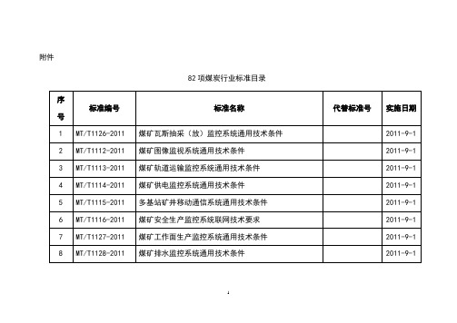
2011煤矿82项煤炭行业标准
矿井降温技术规范
2011-9-1
21
MT/T661-2011
煤矿井下用电器设备通用技术条件
MT/T661-1997
2011-9-1
22
MT451-2011
煤矿用隔爆型低压三相异步电动机安全性能通用技术规范
MT451-1995
2011-9-1
23
MT1137-2011
矿用红外遥控器通用技术条件
MT/T386-1995
2011-9-1
75
MT1125-2011
煤矿井下用塑料编织袋
2011-9-1
76
MT/T1134-2011
矿用卡箍式环型挠性管接件
2011-9-1
77
MT/T392-2011
煤矿用钻杆圆锥螺纹体型式和基本尺寸
MT/T392-1995
2011-9-1
78
MT/T786-2011
2011-9-1
50
MT/T1152-2011
煤炭工业露天矿工程建设项目可行性研究报告编制标准
2011-9-1
51
MT/T1153-2011
煤炭工业选煤厂工程建设项目可行性研究报告编制标准
2011-9-1
52
MT/T1124-2011
煤矿冻结法开凿立井工程技术规范
2011-9-1
53
MT/T1150-2011
64
MT213-2011
煤矿用反井钻机通用技术条件
MT213-1991
2011-9-1
65
MT/T587-2011
液压支架结构件制造技术条件
MT/T587-1996
2011-9-1
MT73 MT110 MT115 MT116系列产品说明书

CONTROLS Instruction ManualCycling and Reversing Variable Speed DC Control with on Board Dynamic BrakingA-5-3159HQuick JumpWarrantyDart Controls, Inc. (DCI) warrants its products to be free from defects in material and workmanship. The exclusive remedy for this warranty is DCI factory replacement of any part or parts of such product which shall within 12 months after delivery to the purchaser be returned to DCI factory with all transportation charges prepaid and which DCI determines to its satisfaction to be defective. This warranty shall not extend to defects in assembly by other than DCI or to any article which has been repaired or altered by other than DCI or to any article which DCI determines has been subjected to improper use. DCI assumes no responsibility for the design characteristics of any unit or its operation in any circuit or assembly. This warranty is in lieu of all other warranties, express or implied; all other liabilities or obligations on the part of DCI, including consequential damages, are hereby expressly excluded.NOTE: Carefully check the control for shipping damage. Report any damage to the carrier immediately. Do not attempt to operate the drive if visible damage is evident to either the circuit or to the electronic components.All information contained in this manual is intended to be correct, however information and data in this manual are subject to change without notice. DCI makes no warranty of any kind with regard to this information or data. Further, DCI is not responsible for any omissions or errors or consequential damage caused by the user of the product. DCI reserves the right to make manufacturing changes which may not be included in this manual.TABLE OF CONTENTSINTRODUCTION (2)CONTROL FEATURES (2)130 SERIES HEATSINK AND MOUNTING (3)DIMENSIONS (3)MODEL SELECTION (4)WIRING PROCEDURE & FUSING (4)TERMINAL STRIP WIRING INSTRUCTIONS (4)130 HOOK-UP DIAGRAM (6)CONTROL START-UP (6)TRIMPOT ADJUSTMENT CHART & PROCEDURE (7)CONTROL MODIFICATIONS (9)SPEEDPOT KIT ASSEMBL Y (9)OPTION DESCRIPTIONS (9)IN CASE OF DIFFICULTY (11)SPECIFICATIONS (11)TYPICAL MOTOR CURRENTS (11)1INTRODUCTION· The 130 series reversing speed control is designed to provide instant reversing, quick precisestopping or rapid cycling for a wide range of DC motor applications. The 130 series controlsoutperform other dynamic braking and reversing controls by utilizing Dart’s unique zero speed detect and solid state assisted dynamic braking circuits. These circuits eliminate the contact arcing andfailed braking problems associated with other reversing and dynamic braking controls. Dart’s zerospeed detect circuit also eliminates the motor problems associated with plug reversing a motor by not reapplying power to the motor until zero speed is obtained.·The 130 series controls are also designed so that upon a power loss condition to the control or an E- stop condition, the control will drop into a dynamic brake condition to safely and quickly bring themotor to a stop and remain there until power is reapplied and a run condition is recognized.·The 130 series variable speed control come in an extremely small package size and fits the industry standard footprint for both vertical and horizantal mounting patterns.·The 130 series variable speed control is available in a range of 500mA through 10Adc output at120Vac or 240Vac input. This represent a Horsepower range of 1/50 through 1 at 90Vdc out or 1/25 through 2 at 180Vdc out.·The control is designed for DC Permanent Magnet and Shunt Wound motors in the abovehorsepower ranges.·Incoming AC voltage is converted to adjustable full wave rectified DC voltage to operate the DCmotor. Also, a full wave field voltage is provided for shunt wound motors.·The control incorporates transient voltage protection with adjustable current limit which fits into acompact package. It also features adjustable IR compensation along with adjustable minimum andmaximum speeds settings.·Available softstart option. (Consult factory for your OEM specific needs)· Listed, file #E78180CONTROL FEATURES· MINIMUM SPEED - Allows adjustment of the motor speed when the speedpot is set at minimum (CCW). This permits the user to eliminate “Deadband” on the main speed control, permitting zero calibration. Clockwise rotation of “MIN” trimpot increases speed.· MAX SPEED (Maximum Speed) - Allows adjustment of the motor speed when the speedpot is set at maximum (CW). This permits the user to eliminate the top end “Deadband”, which will provide full speed at maximum rotation. Rotation of the “MAX” trimpot in the clockwise direction increases the maximum motor speed.· I.R. COMP (Speed Regulation) - This allows for adjustment of the circuitry that controls the speed regulation of the motor. The circuitry controls armature speed by changing the armature voltage to compensate for increased or decreased motor loading. Clockwise rotation of the “IR COMP” trimpot will increase compensation.2· CUR. LIM. (Current Limit) - Provides protection from excessive armature current by limiting themaximum armature current the control can provide. This enables adjustment of the maximum torque the motor can deliver. Torque adjustment (Cur. Lim.) is preset at 125% of rated motor torque (current) based on horsepower. Clockwise rotation of the “CUR. LIM.” trimpot increases the torque (current) the control will provide.· BARRIER TERMINAL BLOCKS - Allows for connection of AC lines, motor leads, motor field (ifneeded), speed potentiometer and Fwd-Brake-Rev inputs.· ONBOARD DYNAMIC BRAKE RESISTOR - Consult factory for available remote mounting option of Brake resistor.· POWER LOSS BRAKE - Upon a power loss to the control or an E-stop command, the control will drop into a dynamic brake condition to safely and quickly bring the motor to a stop and remain there until power is reapplied and a run condition is recognized.130 SERIES HEATSINK AND MOUNTINGDIMENSIONSAUXILIARY HEATSINK -HS(125D) STANDARD HEATSINK3MODEL SELECTIONNOTE:* With suitable external heatsink (where 130 extrusion temperature does not exceed 70° C.), maximum rating forOutput Amps can be increased to 10 ADC output at up to 1Hp at 90VDC or 2Hp at 180VDC.WIRING PROCEDURE & FUSING1. Size all wires which carry armature or line currents AS SPECIFIED BY NATIONAL, STATE, AND/ OR LOCAL CODES. All other wires may be # 18 AWG or smaller as permitted by local code.2. Separate control wires from the armature and AC lines when routed in conduit or in wire trays.3. Fusing - The motor and control are protected against overloads by the current limit circuit and acustomer installed fuse in the AC line. THIS PROTECTION ALREADY MAY BE PROVIDED BY THE CUSTOMER WITH CIRCUIT BREAKERS OR FUSES IN BOTH MAIN LINES. IF NOT:FOR 120 VAC INPUT - fuse or breaker protection should be added by the customer inline with the Hot AC Line (see following chart).FOR 240 VAC INPUT - fuse or breaker protection should be added by the customer inline with both Hot AC Lines (see following chart).FUSING ADDED BY CUSTOMER (Bussman ABC or Little Fuse 314 Series ceramic fuses)TERMINAL STRIP WIRING INSTRUCTIONSUpper board terminal block connections (P4)P4-1(AC1 / L) – For single phase AC lines, (120VAC for US or 240VAC for Europe) connect the Hot side of your AC line to this terminal. For systems with two hot AC lines, (240VAC for US)connect either of the Hot AC lines to this terminal.4P4-2(AC2 / N) – For single phase AC lines, (120VAC for US or 240VAC for Europe) connect the Neutral side of your AC line to this terminal. For systems with two hot AC lines, (240VAC forUS) connect either of the Hot AC lines to this terminal.P4-3(A1) – For clockwise rotation of your motor in the Fwd. Direction, connect the Plus (+) Armature wire of the motor to this terminal.P4-4(A2) – For counter-clockwise rotation of your motor in the Rev. direction, connect the Minus (-) Armature wire of the motor to this terminal.P4-5(REV) – This is the reverse direction input terminal. When connected to the COM terminal, the control will release its brake circuit and accelerate to its set point in the reverse direction. When the connection to the COM terminal is opened the control will brake to zero speed. Theconnection to the COM terminal can be made via a mechanical switch, a relay contact, or anungrounded solid state open collector type switch. Switching requirements are 5VDC at lessthan 1ma.P4-6(FWD) – This is the forward direction input terminal. When connected to the COM terminal, the control will release its brake circuit and accelerate to its set point in the forward direction. When the connection to the COM terminal is opened the control will brake to zero speed. Theconnection to the COM terminal can be made via a mechanical switch, a relay contact, or anungrounded solid state open collector type switch. Switching requirements are 5VDC at lessthan 1ma.P4-7(COM) – This is the common terminal for the forward and reverse speed/dynamic brake commands. This terminal should not be grounded or tied to any other terminal.Lower board terminal block connections (P1)P1-4(-A/-F) – DO NOT use for Permanent Magnet Motor. This supplies -Field voltage for a SHUNT WOUND MOTOR (refer to field voltage table). For motors with dual voltage field (ie. 50/100V or 100/200V), make sure highest value is connected. Note: When connecting to this terminal, you will need to use a fork or ring connector placed directly under the screw head.P1-5 (+F) – DO NOT use for Permanent Magnet Motor. This supplies +Field voltage for a SHUNT WOUND MOTOR (refer to field voltage table). For motors with dual voltage field (ie. 50/100V or 100/200V), make sure highest value is connected.P1-6(Speedpot Hi) – Connects to high side (white wire) of Speedpot (CW end). This is an internal+12VDC. For start-stop applications, the connection between this terminal and Speedpot HI can be opened and closed by a SPST switch. INPUT MUST NOT BE GROUNDED!P1-7(Speedpot Wiper) – Connects to wiper (red wire) of Speedpot (center lead). For Voltage Follower applications, this INPUT MUST NOT BE GREATER THAN +12V MAXIMUM AND MUST NOT BE G ROUNDED!P1-8(Speedpot Lo) – Connects to Low side (orange wire) of 5K Speedpot (CCW end). This input is raised and lowered by the MIN. trimpot (5K). Electronic speed input (voltage follower) may bereferenced to Speedpot LO if the MIN trimpot adjustments are to be active. Otherwise, inputsmay be referenced to -ARM, which will bypass the MIN trimpot. INPUT MUST NOT BEGROUNDED!5130 HOOK-UP DIAGRAMCONTROL START-UPWARNING: ALL POWER MUST BE TURNED OFF BEFORE PROCEEDING!1. Recheck all wiring. Accidental grounds to loose or pinched wires on the armature or speedpot wires may damage the control when power is applied.2. Check to see that incoming service is of correct voltage.3. Turn speedpot to zero (fully CCW).4. Turn power on, close contact from COM(P4-7) to either FWD(P4-6) or REV(P4-5) and advancespeedpot while observing motor rotation. Power must be off before step 5 can beaccomplished!5. If motor rotation is incorrect for the direction selected, turn power off at external disconnect andreverse the A1 and A2 motor connections.66. Check for satisfactory operation throughout the speed range.7. Open the FWD/REV connection to COM to verify motor brakes to zero speed.8. If operation is satisfactory, no readjustments are needed.9. If instability or surging is observed, or if maximum and minimum speed settings need further adjustments then see “TRIMPOT ADJUSTMENT CHART & PROCEDURE”.10. For other problems, consult page 10, “IN CASE OF DIFFICULTY”.TRIMPOT ADJUSTMENT CHART & PROCEDURE78CONTROL MODIFICATIONSINHIBITTWO SPEED OPERATION USIN G TWO 5K SPEEDPOTS TWO SPEED OPERATION USIN G TWO 10K SPEEDPOTSSPEEDPOT KIT ASSEMBLYCUSTOMER'SOPTION DESCRIPTIONS-K optionAcceleration Time Ranges Factory Installed This option provides the Accel time shown below. The standard Accel time is 0.5 seconds. ACCELERATION TIME------------------------------------------------------------------------------------------ 6 secondsUSE STANDARD HOOK-UPIN CASE OF DIFFICULTYIf control still will not operate, consult your Dart Distributor or Representative.0.500.42---------- 1.000.810.800.402.001.601.200.603.502.701.801.401/501/201/81/4HorsepowerTypical AC Amps (120VAC)Typical Arm Amps (120VAC)Typical AC Amps (240VAC)Typical Arm Amps (240VAC)4.403.402.201.701/3 6.505.003.302.501/29.308.204.803.703/413.2010.906.505.001.0----------9.708.201.5----------12.9011.602.0SPECIFICATIONSAC input voltage --------------------------------------------------------------------------- ±10% of rated line voltage Acceleration ------------------------------------------------------------------------------- 0.5 seconds standard 125D Amps - DC output; (Models 130XX12 & 132XX25)--------------------------------------- 500 mA to 1.2 ADC (Models 130LC100 & 132LC200)------------------------------------ 500 mA to 5.5 ADC* (Models 130HC100 & 132HC200)------------------------------------ 500 mA to 10 ADC Controller overload capacity ------------------------------------------------------------------- 200% for one minute Current limit trimpot range; (Models 130XX12 & 132XX25)------------------------------------- 0.3 to 3 ADC (Models 130XX100 & 132XX200)----------------------------------- 1 to 18 ADC Deceleration 0.5 seconds (standard 125D)Dimensions and weights:Drive service factor ------------------------------------------------------------------------------------------------------ 1.0Efficiency ------------------------------------------------------------------------------------------------------- 85% typical Input frequency -------------------------------------------------------------------------------------------- 50 or 60 Hertz Max. trimpot speed range ------------------------------------------------------------ 60% to 110% of base speed Min. trimpot speed range ---------------------------------------------------------- 0% to 30% of maximum speed Power devices ----------------------------------------------------------------------------------------- isolated case tab Shunt field voltage ----------------------------------- 100VDC for 120VAC input; 200VDC for 240VAC input Shunt field current -------------------------------------------------------------------------------- 1 amp DC maximum Speed control ---------------------------------- via 5Kohms .5W potentiometer or 0-10VDC isolated signal Speed range ------------------------------------------------------------------------------------------------------------- 50:1Speed regulation ----------------------------------------------------------------------------------- ±1% of base speed Temperature range -------------------------------------------------------- -10° to 45° C. ambient (15° to 115° F.)Terminal Block Torque Setting -------------------------------------------------------------- 4.4 in. lb. Max or .5Nm Transient protection ------------------------------------------------------------------------------------------------ G-Mov Trigger ---------------------------------------------------------------------------------------------------------- opto-isolator Start/Brake cycle per minute (LC Models)---------------------------------------------------------------- 3 per min**(HC Models)--------------------------------------------------------------30 per min**Approval -------------------------------------------------------------------------------------------------------* With suitable external heatsink (where 130 extrusion temperature does not exceed 70° C.), maximum rating for output amps can be increased to 10 amps D.C.** Cycles per minute are based on typical inertia type loads. Higher cycle per minute rates may be achieved with constant torque or low inertia type loads. Lower cycle rates may be required for very high inertia type loads.TYPICAL MOTOR CURRENTS- Notes -- Notes -。
机舱油类记录簿填写指南1.1
机舱油类记录簿填写指南(2011)《〈73/78防污公约〉修正案》已经正式实行,为了方便广大轮机员尽快适应新修正并正确填写机舱《油类记录簿》,特编写此指南。
本指南包含了机舱《油类记录簿》中《记载项目一览表》的C、D、E、H项。
供参考。
一、《油类记录簿》的常规填写规范:1、划去不适用项目划去不适用项目应用直尺划单横线。
2、日期填写日期填写格式应为dd-mm-yyyy。
填写内容应为该项操作完成的时间。
3、数据填写填写小数点后位数,参阅IOPPC内关于舱容的小数点后位数。
数据单位必需填写。
注意区分m3/MT等,避免笔误。
4、中文、英文的使用设备英文名的描述与IOPPC上一致。
填写时先填中文项,然后换行填写对应英文项。
如中文项一行内填写不完则换行填写,待中文项填写完整后再换行填写对应英文项。
即中文英文各占一格、互不穿插。
5、简化对相关的舱柜进行编号可以简化《油类记录簿》的填写。
(非强制)6、签注每完成一个字母代号的记录都需要填写人员签注并标明日期。
签注格式为:签名(空格)职务(空格)英文名(空格)dd-mm-yyyy 。
记录每填写一页后船长签字为该页记录完成。
7、修改笔误认真填写不要随意涂改。
如必须修改,应用直尺划单横线将错误部分划去,并在修改部分附近签注。
禁止涂黑、修正液覆盖等错误操作。
8、实例:船名NAME OF SHIP 年池NIAN CHI船舶编号或呼号DISTINCTIVE NUMBER BPGBOR LETTERS货油/压载的作业(油轮)* / 机器处所的作业(所有船舶)*CARGO/BALLAST OPERA TIONS ( OIL TANKERS ) * / MACHINERY SPACEOPERA TIONS ( ALL SHIPS ) *Delete as appropriate Signature of Master 周玉才二、C残油(油泥的收集、转移、和处理)11 残油的收集该项目主要用以每周结存,请每7天记录一次。
CMTC-MT-2011-06 止移件使用要点
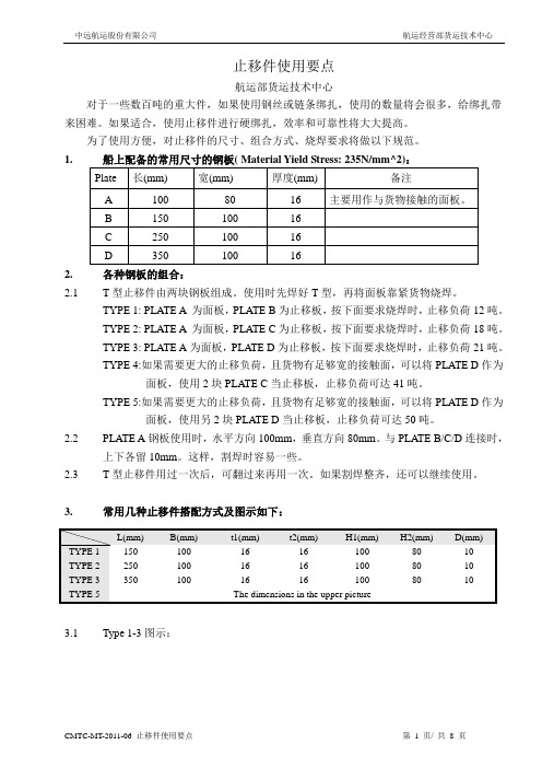
止移件使用要点航运部货运技术中心对于一些数百吨的重大件,如果使用钢丝或链条绑扎,使用的数量将会很多,给绑扎带来困难。
如果适合,使用止移件进行硬绑扎,效率和可靠性将大大提高。
为了使用方便,对止移件的尺寸、组合方式、烧焊要求将做以下规范。
1.2.各种钢板的组合:2.1T型止移件由两块钢板组成。
使用时先焊好T型,再将面板靠紧货物烧焊。
TYPE 1: PLATE A 为面板,PLATE B为止移板,按下面要求烧焊时,止移负荷12吨。
TYPE 2: PLATE A 为面板,PLATE C为止移板,按下面要求烧焊时,止移负荷18吨。
TYPE 3: PLATE A为面板,PLATE D为止移板,按下面要求烧焊时,止移负荷21吨。
TYPE 4:如果需要更大的止移负荷,且货物有足够宽的接触面,可以将PLATE D作为面板,使用2块PLATE C当止移板,止移负荷可达41吨。
TYPE 5:如果需要更大的止移负荷,且货物有足够宽的接触面,可以将PLATE D作为面板,使用另2块PLATE D当止移板,止移负荷可达50吨。
2.2PLATE A钢板使用时,水平方向100mm,垂直方向80mm。
与PLATE B/C/D连接时,上下各留10mm。
这样,割焊时容易一些。
2.3T型止移件用过一次后,可翻过来再用一次。
如果割焊整齐,还可以继续使用。
3.常用几种止移件搭配方式及图示如下:TYPE 13.1Type 1-3图示:3.2Type 5图示:4.烧焊的基本常识。
4.1典型焊缝横切面4.2烧焊的道数当焊脚尺寸(焊脚高度)小于6mm时,烧焊时可以就走一道。
当焊脚尺寸(焊脚高度)8-10mm时,烧焊时要分3道走;12mm以上时,要走6道。
不按道数烧焊,难以保证烧焊质量。
4.3烧焊的强度烧焊的强度,直接与焊缝厚度(THROAT THICKNESS)及烧焊质量有关。
检查焊缝时,首先要确保焊缝厚度足够。
可以根据焊缝厚度和焊脚高度的比例关系来衡量。
MT146.2-2011清晰版

40
Ⅱ
一次
50
Ⅲ
一次
7.4.3 判定规则执行 GB/T2829-2002 中 5.11 的规定。
判定组数 [Ac,Re] [0,1] [0,1] [0,1]
试件安装方法见图 4。
1-杆体;2—拉力架底垫;3—调节板(孔径 60mm);4—托盘;5—球垫;6-螺母
图 4 托盘承载力试验方法示意图
6.6.2 测试 测试时,加载时速度控制在(10~20)kN/min 范围内,托盘被拉穿前的最大力即为托盘承载力。
6.7 锚固力试验 按 MT146.1 中 6.8 的规定试验。
1—杆体;2—托盘;3—球垫;4—螺母
图 2 无纵肋螺纹钢式树脂锚杆金属杆体及附件 4.1.3.2 等强螺纹钢式树脂锚杆金属杆体及附件,如图 3 所示。
1—杆体;2—托盘;3—螺母
图 3 等强螺纹钢式树脂锚杆金属杆体及附件
2
MT146.2—2011
4.2 规格
产品规格应符合表 1 规定。
表 1 产品规格
7.4.2 型式检验的样品应从出厂检验合格的产品中,按 GB/T10111 的规定进行随机抽样。抽样检验采 用 GB/T2829-2002,抽样方案及有关数据见表 6。
试验组别
1 2 3
不合格分类
A B C
表 6 型式检验抽样方案及有关数据
不合格质量水平 RQL 30
判别水平 DL Ⅰ
抽样方案类型 一次
4 产品分类
4.1 分类 4.1.1 总则
产品按杆体材料和结构形式进行分类。
1
4.1.2 麻花式树脂锚杆金属杆体 麻花式树脂锚杆金属杆体及附件,如图 1 所示。
MT146.2-2011
MT2011 Preliminary_ver0.0
0° C ≤TA ≤+70° C
VRCHG Recharge Threshold, below regulation voltage limit Trickle Charge to fast charge transition threshold BAT Over-voltage Threshold 1 cell, measured on BAT VBAT_REG-VBAT measured on BAT
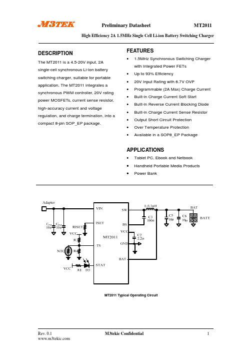
M3TEK
Preliminary Datasheet
MT2011
High Efficiency 2A 1.5MHz Single Cell Li-ion Battery Switching Charger
DESCRIPTION
The MT2011 is a 4.5-20V input, 2A single-cell synchronous Li-Ion battery switching charger, suitable for portable application. The MT2011 integrates a synchronous PWM controller, 20V rating power MOSFETs, current sense resistor, high-accuracy current and voltage regulation, and charge termination, into a compact 8-pin SOP_EP package.
Rev. 0.1
M3tekic Confidential
2
M3TEK
Preliminary Datasheet
MT2011
High Efficiency 2A 1.5MHz Single Cell Li-ion Battery Switching Charger
MT11远程表产品说明书

MT Series——Remote MeterUser ManualModels:MT11Contents1.Important Safety Instructions (1)2.Overview (2)3.Product classification (3)4. Installation (4)4.1 Base of MT11 (Optional accessory) (4)4.2 Wall installation steps (5)4.3 Surface mounting steps (7)5.Product Features (8)5.1 Front View (8)5.2 Rear View (9)6.Display and operation (11)6.1LCD display (11)6.2 Auto global view mode (12)6.3 Temperature units (14)6.4 Clear the generated energy (14)6.5 Battery type (15)6.6 Fault indication (19)7.Technical Specifications (20)Thank you for selecting the remote meter.General safety information•Please contact our company or transportation if the product has been damaged.•Please read this manual carefully before using the product and pay attention to the safety information.•Keep the product away fromrain, exposure, severedust, vibrations,corrosive gas and intense electromagnetic interference. •Do not allow water to enter the product.•There are nouse rserviceable parts inside the product. Do not disassemble or attempt to repairit.Recommendations•The MT11 is only allowed to connect with DR N series charge controller.Please confirm before purchase and installation.• Please do not install MT11 in a situation with strong electromagnetic interference.The MT series remote meter is an accessory which is compatible with the DuoRacer series controller. It can monitor the running data and working status of the controller via the remote meter. The remote meter can browse the controller’s parameters, set the battery typeand temperature unit, and clean the generated energy.It is suitable for RV, Camper, Boat, and so on.Features:•Automatically identify and display the type,model and relevant parameter data of controllers.•Real-time display the operational data and working status of the connected devices indigital,graphics and textual forms by a large-screen multifunction LCD.•Three touch buttons are easy and quick to operate.•No need for external power supply. Charge controller supply the power for MT11.•It can browse the controller’s parameters, set the battery typeand temperature unit, and clean the generated energy.•Real-time display of failure information of the connected devices. •Longer communication distance based on RS485.1) MT11(include the 1.5m communication cable)✦ Remote meter MT11✦ 1.5m communication cable(Model: CC-RS485-RS485-3.81-4P-150)✦Base of MT112) MT11 (include the 5m communication cable)✦Remote meter MT11✦5m communication cable(Model: CC-RS485-RS485-3.81-4P-500)✦Base of MT113) MT11 (include the 10m communication cable)✦Remote meter MT11✦10m communication cable(Model:CC-RS485-RS485-3.81-4P-1000)✦Base of MT114) MT11(Do not include the communication cable)✦Remote meter MT11✦ 1.5m communication cable(Model: CC-RS485-RS485-3.81-4P-150)✦Do not include Base of MT11NOTE: The user can purchase the product according to the requirement.4.1 Base of MT11 (Optional accessory)4.2 Wall installation stepsStep1:Locate and drill screw holes based on the Frame Mounting dimension of the base,and erect the plastic expansion bolts.Step2:Use four PA4.2×32 self-tapping screws to fix the Frame.Step3:Remove the decorative shell.Step4:Use four M4×8 pan head screws to mount MT11 Surface on the Frame. Step5:Install the decorative shell.4.3 Surface mounting stepsStep1: Locate and drill screw holes based on the installation size of the surface.Step2: Remove the decorative shellStep3:Use four M4×8 cross recessed pan head screws with M4 nuts to mount MT11 surface onto the panel.Step4:Install the decorative shellNOTE:Take full consideration of the plugging/unplugging space of the communication cable and the length of the cable during installation to see if they are appropriate.5.1 Front ViewLCD display screenMan-machine interaction operation interface. Refer to the chapter 5 display and operationButtonsThe meter buttons include two function buttons and one switch button.Press the button1.PV array parameters2.Storage battery parameters3.Browse the start battery parameters automatically ()Browse the PV array parameters5.2 Rear View✦RS485communicationportIt is used to connect the controller which Power the MT11. ✦Communicationcable’s modelsCC-RS485-RS485-3.81-4P-150(Included)CC-RS485-RS485-3.81-4P-1000(Optional)CC-RS485-RS485-3.81-4P-2000(Optional)✦Pins definition6.1LCD displayIconIconBATT1 battery capacityBATT1battery capacity BATT1battery capacity BATT1battery capacity BATT1battery capacityDisplay the parametersDisplay the parametersDisplay the parameters①Battery power calculated by the linear relationship disconnect voltage of low voltage and float charging voltage.6.2 Auto global view modeOperation:Step1: Press the button, is appear.Step2:Press the button, select the .Echo Loop:PV voltage ——PV current ——PV power——Battery power——BATT1 voltage——BATT1 current——Max. BATT1 voltage——Min.BATT1 voltage——BATT1 temperature——BATT1 battery type——BATT2 voltage——BATT2 current——Max. BATT1 voltage——Min.BATT2 voltage——PV voltage6.3 Temperature unitsOperation:Step1: Press the button under the battery temperature interface. Step2: Press the button to select the temperature unit.Step3: Press the button to set successfully.6.4 Clear the generated energyPress the andbutton and hold on 5s to clear the generated energy.6.5 Battery type1)Operation:Step1: Press the button and hold 5s under the battery type interface. Step2: Press the button when the battery type interface is flashing. Step3: Press the button to confirm the battery type.2) Battery typeBATT112V Sealed BATT124V SealedBATT112V Gel BATT124V GelBATT112V Flooded BATT124V FloodedLiFePO LiFePOLi-NiCoMn (3S) Li-NiCoMn (6S)UserCAUTION:The battery voltage is set as default and not changeable when selecting the default battery type. Please change to “User” battery type before adjusting the battery voltage.CAUTION: Set the voltage of the “User” battery type via PC software only.1) Lead-acid Battery Control Voltage ParametersThe parameters are in the 12V system at 25 ºC. Please double the1) When the battery type is sealed, gel, flooded, the adjusting range of equalizing duration is 0 to180min, and boost duration is 10 to180min.2) The following rules must be observed when modifying the value of the parameter in user battery type(factory default value is the same as sealed type):A. Over Voltage Disconnect Voltage > Charging Limit Voltage ≥ EqualizeCharging Voltage ≥ Boost Charging Voltage ≥ Float Charging Voltage > Boost Reconnect Charging Voltage.B. Over Voltage Disconnect Voltage > Over Voltage Reconnect VoltageC. Low Voltage Reconnect Voltage > Low Voltage Disconnect Voltage ≥Discharging Limit Voltage.D. Under Voltage Warning Reconnect Voltage > Under Voltage WarningVoltage ≥ Discharging Limit Voltage.Boost Reconnect Charging voltage > Low Voltage Disconnect Voltage.2)Lithium Battery Control Voltage ParametersThe parameters are in the 12V system at 25 ºC; please double theThe following rules must be observed when modifying the parameter values in User for the lithium battery.A.Over Voltage Disconnect Voltage>Over charging protectionvoltage(Protection Circuit Modules(BMS))+0.2V※;B.Over Voltage Disconnect Voltage>Over Voltage Reconnect Voltage=Charging Limit Volt age ≥ Equalize Charging Voltage=Boost Charging Voltage ≥ Float Charging Voltage>Boost Reconnect Charging Voltage;C.Low Voltage Reconnect Voltage>Low Voltage Disconnect Voltage ≥ Discharging Limit Voltage;D.Under Voltage Warning Reconnect Voltage>Under Voltage Warning Voltage≥ Discharging Limit Voltage;E.Boost Reconnect Charging voltage> Low Voltage Reconnect Voltage;F.Low Voltage Disconnect Voltage ≥ Over-discharging protection voltage(BMS)+0.2V.WARNING:The voltage parameters of the lithium battery can be set, but you must refer to the voltage parameters of lithium battery BMS.WARNING: The required accuracy of BMS shall be at least 0.2V. If the deviation is higher than 0.2V, the manufacturer will assume no liability for any system malfunction caused by this.6.6 Fault indicationindicatorBattery levelshows full, batteryframe blink, faulticon blink.Battery levelshows empty,battery frame blink,fault icon blink.Battery levelshows currentcapacity, batteryframe blink, faulticon blink, thetemperature iconblink.flashing Battery level shows empty, battery frame blink.No alarm for limited voltage fault when using Lithium batteries.Any changes without prior notice! Version number:1.1BEIJING EPSOLAR TECHNOLOGY CO., LTD. Tel: +86-10-82894896 / 82894112Fax: +86-10-82894882E-mail:******************Website: 。
2011年MT工作方案

汕头新锐2011年MT工作方案人力行政部2011年2月汕头市新锐体育用品有限公司MT工作方案2011年MT总体方案一、目的为更好地满足汕头新锐业务的高速发展需求,逐步建立起有效的人才储备机制,进一步优化及提升团队综合素质能力,提高对人才的自我造血功能。
二、需求人数:8人(待定)三、招聘人数: 10-15人(待定)四、招聘区域:汕头市五、项目说明汕头新锐MT工作安排方案共分为五个阶段,将“MT需求调查→招聘实施→店铺实习→定岗培养→结业入职”划分开,每个阶段设定责任人并制定具体实施方案。
而MT则将通过:“入职集训→店铺实习→答辩应聘→定岗培养→结业入职”五个阶段,让MT从“校园人→社会人→企业人”进行转变,而答辩应聘阶段则打破了人力行政部门与MT需求部门之间的对人才界定的传统认识,由用人部门对答辩后的MT进行面试评估,而MT也通过自己的表现参加应聘,从而达成一种双向的需求匹配。
第一阶段: MT需求调查阶段♦责任人:人力行政部负责人♦工作完成要求:1、汕头新锐各部门未来两年人事规划,明确岗位及人员需求;2、确定MT招聘具体岗位,招聘层次,及完成时间要求;(确定MT薪金等要素)3、汕头新锐2011年MT工作方案确定;♦说明:明确岗位及人员需求的具体方向及数量,根据需求确定MT工作定位、招聘方向及MT工作目标。
(注:此为结业入职人数,招聘人数为10-14人。
)第二阶段: MT招聘实施阶段♦责任人:♦工作完成要求:1、确定招聘院校并联系;2、制订完成招聘方案;3、完成招聘资料准备;4、跟踪各部门人员需求,确定岗位培养方案;5、完成入职报到流程及相关手续安排(确定好入职相关手续办理要素);6、实施招聘,筛选MT;♦说明:此阶段需要完成招聘院校确定、资料准备、招聘流程及方式、报到流程及安排;并根据第一阶段的要求,确定工作时间及步骤。
汕头市新锐体育用品有限公司MT工作方案【具体方案】一、原则择优录取、优胜劣汰、统筹分配、逐级培养。
2011SHIMANO轮组目录

从设计到制造,一条完整综合的 制作流程
从制造到装配,SHIMANO 的无与伦比的质量承诺延伸 到整个生产过程。
03
轮组目录 2011
空气动力学性能创新
顶尖设备下的风洞试验
我们运用尖端技术完成风洞试验,结果显示16辐条车轮的空气动力学性能 取得最佳表现。事实上,以48km/h的速度骑行一小时,使用16辐条轮组能 将时间缩短整整一分钟。我们还进行一系列试验以测量空气阻力和侧风的影 响。
冷锻技术的创新
SHIMANO 独有的冷锻技术实现平滑的 滚动并实现全世界认可的强度,性能和 可靠性。
碗和轴档轴承的创新
与只能承受地面垂直方向应力的工厂制造轴承相比, SHIMANO 碗轴档轴承技术提供能够承受直行时的径向 载荷和转弯时的倾斜载荷的强度。骑行更快速,所需维 护更少,使用寿命更长。
载荷方向 载荷分布方向
空气型辐条
为 提 高 空 气 动 力 性 能,SHIMANO 空 气 型 辐 条 采 用 椭圆形截面,而非圆形。
1
100
1.6
70
2.4
38
16 和 32 辐条的比较
与 32 辐条轮组相比,以 48km/h 速度骑行一小时,使用 16 辐条轮组能 将时间缩短整整一分钟。
48km/h 下的阻力
0.5
0.45 32辐条轮组
轮 组 目 录 2 0 1 1 02
手工打造的品质
所有 SHIMANO 轮组均符合世界知名零部件的质量 控制标准。
受过专门培训并持有相应资质证书的工匠手工制造出每一只 SHIMANO 车 轮。这些专家在工作中投入激情和专注,如一条不可或缺、倾注个人情感 的纽带,将 SHIMANO 工程师追求完美骑行的精神和全世界骑行者的终极 表现联系起来。SHIMANO 生产花鼓、辐条、轮圈和轴承。每一只车轮都由 SHIMANO 生产的零件装配而成,也同样符合世界知名零部件的质量控制标 准。并且,为满足日后完善追溯查询的需要,所有 SHIMANO 车轮都标有唯 一的序列号。对优秀品质的一贯追求是 SHIMANO 历史悠久、无与伦比的宝 贵传统。这是SHIMANO 价值所在。
mt1162.4-2011
mt1162.4-2011
《MT1162.4-2011》是中国国家标准中关于钢筋混凝土结构技术规程的一部分。
该标准主要涉及了钢筋混凝土结构设计、施工和验收的技术要求。
具体来说,这部标准规定了钢筋混凝土结构的设计原则、构件尺寸、钢筋用量、混凝土配合比、施工工艺、验收标准等方面的内容。
《MT1162.4-2011》标准的发布对于规范钢筋混凝土结构的设计和施工具有重要意义。
首先,该标准明确了钢筋混凝土结构设计的基本原则和要求,包括结构的安全性、耐久性、使用功能等方面的考虑,有利于提高工程质量。
其次,标准中对于施工工艺和验收标准的规定,可以有效地指导施工方按照标准要求进行施工和验收,确保工程质量达标。
从实际应用的角度来看,《MT1162.4-2011》标准的实施可以提高钢筋混凝土结构工程的设计水平和施工质量,有利于保障工程的安全可靠性。
同时,该标准的制定也反映了我国在建筑领域的技术水平和标准化管理的进步,对于促进建筑行业的健康发展具有积极的推动作用。
总的来说,《MT1162.4-2011》标准的发布和实施对于规范钢筋混凝土结构工程具有重要意义,有利于提高工程质量、推动行业发展和保障工程安全。
因此,对于相关从业人员来说,熟悉并严格遵守该标准的要求是非常重要的。
mt871-2011标准
mt871-2011标准
MT871-2011是指中国国家标准GB/T 871-2011《发布]》,该标准的全称为《材料慢变形性能和面积收缩率的测定》。
MT871-2011标准规定了测定材料慢变形性能和面积收缩率的方法。
该标准适用于金属材料、非金属材料、合成材料等的慢变形性能和面积收缩率的测定。
该标准中主要包含了以下内容:
1.范围:规定了该标准适用的材料范围。
2.引用标准:列出了其他相关标准的引用。
3.术语和定义:定义了在该标准中使用的一些术语和定义。
4.试验原理:介绍了测定材料慢变形性能和面积收缩率的基本原理。
5.试验仪器和设备:列出了进行试验所需的仪器和设备,并规定了其要求和使用方法。
6.试验方法:详细描述了测定慢变形性能和面积收缩率的试验步骤,包括样品制备、试验条件、数据采集和计算等。
7.试验结果的表达和报告:规定了试验结果的表达方式和报告要求。
8.试验结果的评定:对试验结果进行评定和判定。
MT871-2011标准的发布旨在规范材料慢变形性能和面积收缩率的测定方法,以提高材料性能测量的准确性和可比性。
该标准适用于材料科学、材料工程、制造工程等领域。
MT维修手册,电路图(PDF精品)

7.5V 转 2.5V
U101:5V 转 2.5V
稳压管输出电压如下:
8. 5V 转 1.25V
U103:5V 转 1.2V
MP2127 是一款通过占空比来控制输出电压的芯片,标准应用如图:输出电压的 大小可以通过可以通过下图的电阻 R1 与 R2 来调节。输出电压
为:
标准应用电路
测试点电压输出如下:
4.电源供电:
P100 第 1、2、 4 脚,输出
电源插口部分是标准插口,和之前内销的插口一样,没有区别。电源的上电顺序 是:电源板先输入 STB3.3V 电压(可在 7 脚测量到 3.3V 电压)。主板在接到 3.3VSTB 电压之后(可测量主板 R106,R463,R464,R454 是否有 3.3V 电压),会对电源 板反馈一个 3V 左右的高电平(可测量主板 R132 低电平,R134 有 3V 左右的高电 平),这时候电源板会输出 24V 给主板(1,2,4 脚会有 12V 或 24V 电压输出), 主板开始正常工作。 电源供电是主板维持正常工作的条件,之前待机给出的电压只能够保证主芯片的 待机部分工作(为了保证待机功耗)。主要的供电方向,请参考 3(机芯主电源 流程图)
图 1 是正常拔插电源的时序,图 2 是待机开机的时序。
3.机芯主电源流程图
.
MIAN POWER(24/12V)
24V 功放 1000MA
5 500MA
1050MA
DC-DCTPS5433 1 U105
DC-DCRT8110+MO S U104
12V
PANEL (800ma
500ma 500ma
第一章机芯描述
功能介绍:
类别
项目
数量
SCHRACK 一般用途多模式电器 MT 系列产品数据表 2010 11 版本JK1说明书
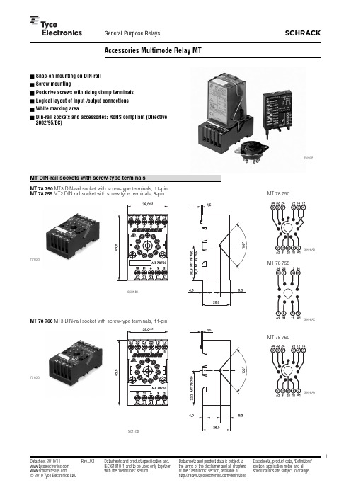
F0235-BF0103-BS0311-BAF0103-BS0311-BBMT 78 755MT2 DIN rail socket with screw type terminals, 8-pinMT 78 760MT3 DIN-rail socket with screw-type terminals, 11-pinMT 78 750V REG.-Nr. 6182, Z E135149Technical dataMT 78 750/755/760/740/745Rated voltage / max. switching voltage AC 240 / 400 VACRated current10 A Dielectric strength coil-contact circuit2500 V rms open contact circuit1500 V rms adjacent contact circuits2500 V rms Clearance / creepage coil-contact circuit W 2.8/4 mmMaterial group of insulation parts IIIa Insulation to IEC 60664-1Type of insulation coil-contact circuitbasic open contact circuitfunctional adjacent contact circuitsbasic Rated insulation voltage 250 V Pollution degree2Rated voltage system 230 / 400 VOvervoltage categoryIII RoHS - Directive 2002/95/ECDIN-rail sockets and retainers:compliant Ambient temperature range -20...+80°C Terminalsscrew Terminal screw torque acc. IEC 619840.5 Nm max.0.7 Nm Wire cross sectionsingle wire 2 x 2.5 mm 2fine wire2 x 2.5 mm 2with bootlace crimp (DIN 46228/1)2 x 1.5 mm 2Insertion cyclesA (10)Max. Insertion Force total 100 NMounting distance W 0, dense packingWeight MT 78 750/76054 g MT 78 755 47 g MT 78 740 62 g MT 78 74556 g Packaging unit25 pcsDIN-rail sockets with screw-type terminalsTypePart Number MT 78 750DIN-rail socket with screw-type terminals 11-pin 1415035-1MT 78 755DIN-rail socket with screw-type terminals 8-pin 3-1415035-1MT 78 760DIN-rail socket with screw-type terminals 11-pin 8-1415034-1MT78 740DIN-rail socket with screw-type terminals, 11-pin8-1393163-3MT78 745DIN-rail socket with screw-type terminals, 8-pin8-1393163-4F0200-BS0366-ASocket system MT 78 740 and MT 78 745n 8/11 pin socket for MT2 / MT3n Double A2 screw for simple further connection of coil supplyMT 78 745MT2 DIN rail socket with screw type terminals, 8-pinAccessories for MT 78 750, MT 78 755, MT 78 760, MT 78 740, MT 78 745TypePart Number MT 28 800Metal retaining clip MT8-1393163-0LED and Protection modules for MT 78 740, MT 78 745TypePart Number MTM T0 0A0Protection diode 1N4007 (A1+, A2-)7-1393163-6MTM U0 730RC-network 110...230 VAC 7-1393163-8LEDMTM L0 024red LED 24 VAC / VDC7-1393163-4Function modules for MT 78 740, MT 78 745TypePart Number MTM Z0 W00Delay ON 7-1393163-9MTM F0 W00Multifunction7-1393163-3Technical data - Function modulesNominal voltage 24...240 VDC / VACMains frequency48...63 Hz Precision of time setting + 0,5 %Readiness for repetition w 0,5 % or 5 ms Influence of temperature w 0,1 %/°CTime range switchable0,05s...240h in 8 rangesRoHS - Directive 2002/95/EC compliant as per product date code 0515Ambient temperature-25...+55 °CFunction modules for MT 78 740, MT 78 745Function Delay ONDelay OFFsingle shot leading edgesingle shot trailing edgeDelay ONtriggerd by signal contact single shotflasher starting with pauseflasher starting with pulseF0203-BF0204-BF0201-BMT sockets for PCB and with solder terminals MT 78 602/603/612/613Technical dataMT 78 602/603/612/613Rated voltage / max. switching voltage AC 240 / 400 VAC Rated current 10 A Dielectric strength coil-contact circuit 2500 V rmsopen contact circuit 1500 V rms adjacent contact circuits 2500 V rmsClearance / creepage coil-contact circuit W 2.8/4 mm Material group of insulation parts IIIa Insulation to IEC 60664-1Type of insulation coil-contact circuit basicopen contact circuit functional adjacent contact circuits basicRated insulation voltage 250Pollution degree 2Rated voltage system 230 / 400Overvoltage category IIIRoHS - Directive 2002/95/ECMT 78 602, MT 78 603compliant as per product date code 0517MT 78 612, MT 78 613compliant as per product date code 0543Ambient temperature range -40...+70°C Terminals pcb, solder teminals Insertion cycles A (10)Max. Insertion Force total 100 N Mounting distance W 0, dense packing Resistance to soldering heat 270°C / 10 s Weight 7 g Packaging unit 25 pcsSockets with solder and PCB terminalsTypePart Number MT 78 612Socket 8-pin with solder terminals 7-1415043-1MT 78 613Socket 11-pin with solder terminals 8-1415043-1MT 78 602Socket 8-pin with PCB terminals 9-1415043-1MT 78 603Socket 11-pin with PCB terminals1415044-1F0107-A F0105-A F0106-AF0104-A S0309-AA。
linux mint 11.0 中文手册.pdf

官方用户指南Linux Mint主版本翻译:邵开来、jluliuchao、皮蛋侠目录LINUX MINT简介 (3)历史 (3)目标 (3)版本号和开发代号 (4)版本 (5)如何获取帮助 (5)下载ISO文件 (7)通过BT下载 (8)安装BT客户端 (8)下载种子文件 (8)通过镜像下载 (9)阅读发行说明 (9)刻录ISO文件到DVD (11)引导L IVE DVD (12)安装L INUX M INT到你的硬盘上 (14)引导顺序 (23)LINUX MINT桌面简介 (24)G NOME桌面 (24)桌面设置 (24)认识主菜单 (26)“位置” 菜单 (26)“系统”菜单 (29)“应用程序”菜单........................................33搜索框 (35)设定你最喜欢的应用程序 (35)创建自定义快捷方式 (36)设定系统登陆时程序自动开启 (36)改变菜单的外观 (36)激活“显示最近打开文档”插件 (38)恢复默认设置 (38)恢复菜单为默认G NOME菜单 (38)软件管理 (39)L INUX M INT中的包管理 (39)软件管理器 (44)菜单 (45)新立得和APT (45)删除应用程序 (46)从菜单中删除 (46)使用APT删除 (46)使用新立得删除 (47)更新你的系统和软件 (47)使用更新管理器 (48)提示与技巧 (54)通过鼠标复制和粘贴 (54)使用T OMBOY记笔记 (55)将邮件和网页保存为PDF (56)总结 (58)Linux Mint简介Linux Mint是一种计算机操作系统,它被设计成可以运行在现今绝大部分的硬件系统上,包括典型的x86、x64构架的个人电脑。
Linux Mint操作系统可以这么被理解,它与Microsoft的Windows、Apple的Mac OS,以及免费的BSD OS充当了相同的角色。
MT111-2011 矿用防爆型低压交流真空电磁起动器

2
MT 111—2011
额定工作电流值应符合 GB/T 762 的规定(除非产品标准另有规定)。
5.2.2 约定发热电流(Ith) 应符合 GB 14048.1-2006 中 4.3.2.1 的规定。
5.2.3 约定封闭发热电流(Ithe) 应符合 GB 14048.1-2006 中 4.3.2.2 的规定。
c )断续周期工作制(见 GB 14048.1-2006 中 4.3.4.3 的规定)。
断续周期工作制由流过电流值、每小时的操作循环次数(见表 1)和负载因数(通电持续率)来确
定。
负载因数(通电持续率)标准值为 40%。
表 1 断续周期工作制的操作条件
使用 类别
断续工作制 工作级别
每小时操作循环数 次/h
本标准是对 MT 111—1998《矿用防爆型低压交流真空电磁起动器》的修订。本标准代替 MT111-1998。 本标准与 MT111-1998 相比,主要变化如下: ---删除了第 3 章符号与代号章节(1998 年版的 3.2 和 3.3) ; ---修改了断续周期工作制的操作条件(1998 年版的表 2,本版的表 1); ---删除了机械环境(1998 年版的表 3); ---删除了按外壳防护等级分(1998 年版的 4.1.4); ---修改了易近部件极限温升(1998 年版的表 8,本版的表 6); ---删除了断续周期工作制绕组的操作条件(1998 年版的表 9); ---修改了隔离开关或隔离换相开关的分断能力(1998 年版的表 15,本版的表 12); ---删除了过载继电器整定值校正内容(1998 年版的表 21 中序号 26); ---删除了运输储存试验内容(1998 年版的表 21 中序号 35); ---修改了型式检验和出厂检验项目(1998 年版的表 21,本版的表 18)。
MT-T 1110-2011 矿用封孔器通用技术条件
目 次前言 (Ⅱ)1 范围 (1)2 规范性引用文件 (1)3 术语和定义 (1)4 分类和型号 (1)5 要求 (2)6 试验方法 (4)7 检验规则 (8)8 标志、包装、运输和贮存 (9)I前 言本标准由中国煤炭工业协会科技发展部提出。
本标准由煤炭行业煤矿安全标准化技术委员会归口。
本标准主要起草单位:煤炭科学研究总院重庆研究院、安标国家矿用产品安全标志中心、河北欧亚特种胶管有限公司、郑州市峰泰机械制造有限公司、巩义市北山口华源液压件厂。
本标准主要起草人:陈福民、付建涛、杨大明、胡继红、何连岐、李天才、李恩宗、曹利波、张安然、石发强等。
本标准为首次发布。
II矿用封孔器通用技术条件1 范围本标准规定了矿用封孔器的术语和定义、技术要求、试验方法、检验规则、标志、包装、运输和贮存。
本标准适用于煤矿井下注水、注浆和抽放瓦斯使用的封孔器(以下简称封孔器)。
2 规范性引用文件下列文件中的条款通过本标准的引用而成为本标准的条款。
凡是注日期的引用文件,其随后所有的修改单(不包括勘误的内容)或修订版均不适用于本标准,然而,鼓励根据本标准达成协议的各方研究是否可使用这些文件的最新版本。
凡是不注日期的引用文件,其最新版本适用于本标准。
GB/T 9969 工业产品使用说明书 总则GB/T 10111 随机数的产生及其在产品质量抽样检验中的应用程序AQ 1043 矿用产品安全标志标识3 术语和定义下列术语和定义适用于本标准。
3.1适用孔径 Applicable hole diameter能使封孔器达到设计封孔效果的钻孔直径。
3.2设计工作压力 Designed working pressure封孔器可供正常使用的压力范围。
4 分类和型号4.1 分类按封孔器的封孔原理可分为水压式、气压式、推胀式、插入式、吸入式封孔器等;按封孔器的用途可分为注水用、注浆用、抽放瓦斯用、抽放瓦斯及注水用封孔器等。
4.2 型号1封孔器按下列规定进行命名:FK □ □- □ / □最大设计工作压力,单位为兆帕(MPa)适用孔径,单位为毫米(mm)工作用途(注水用“S”,注浆用“J”,抽放瓦斯用“W”,抽放瓦斯及注水用“L”)封孔原理(水压式“S”,气压式“Q”,推胀式“T”, 插入式“C”,吸入式“X”)封孔器示例:适用孔径为50mm,额定工作压力为6MPa的抽放瓦斯及注水用封孔器的型号规格表示为FKQL-50/6。
- 1、下载文档前请自行甄别文档内容的完整性,平台不提供额外的编辑、内容补充、找答案等附加服务。
- 2、"仅部分预览"的文档,不可在线预览部分如存在完整性等问题,可反馈申请退款(可完整预览的文档不适用该条件!)。
- 3、如文档侵犯您的权益,请联系客服反馈,我们会尽快为您处理(人工客服工作时间:9:00-18:30)。
P R E L I M I N A R YRF SILICON AND SUBSYSTEMS SOLUTIONSFOR BROADBAND COMMUNICATIONS AND AUTOMOTIVE ELECTRONICSMICROTUNER™ MT2011 SINGLE-CHIP BROADBAND TUNER PRODUCT BRIEFThe MicroTuner MT2011 is a fully integrated single-chip tuner, optimized for digital OpenCable compliant STB applications.MT2011 Single-Chip Broadband Tuner元器件交易网MT2011 SINGLE-CHIP BROADBAND TUNERPRODUCT BRIEFMT2011PB-00070 — Rev 1.0January 2008P R E L I M I N A R YMicrotune, Inc., 2201 10th Street, Plano, TX 75074, USATel: +1-972-673-1600, Fax: +1-972-673-1602, E-mail: sales@, Web site: For a detailed list of office locations, sales offices, and sales representatives, visit our web site at Microtune believes that the information in this document is accurate and reliable, as of the date of this document. Microtune assumes no responsibility for any consequences arising from the use of this information, nor from any infringement of patents or the rights of third parties which may result from its use. No license is granted by implication or otherwise under any patent or other rights of Microtune. The information in this publication replaces and supersedes all information previously supplied, and is subject to change without notice. The customer is responsible for assuring that proper design and operating safeguards are observed to minimize inherent and procedural hazards. Microtune assumes no responsibility for applications assistance or customer product design.The devices described in this document are not authorized for use in medical, life-support equipment, or any other application involving a potential risk of severe property or environmental damage, personal injury, or death without prior express written approval of Microtune. Any such use is understood to be entirely at the user’s risk.Microtune is a registered trademark of Microtune, Inc. MicroTuner, MicroStreamer, VideoCaster, DataCaster, ClearTune, and the Microtune logo are trademarks of Microtune, Inc. All other trademarks belong to their respective companies.Microtune’s products are protected by one or more of the following U.S. patents: 5,625,325; 5,648,744; 5,717,730; 5,737,035; 5,739,730; 5,805,988; 5,847,612; 6,100,761; 6,104,242; 6,163,684; 6,169,569; 6,172,378; 6,177,964; 6,211,745; 6,218,899; 6,268,778; 6,310,387; 6,323,736; 6,355,537; 6,429,502; 6,462,327; 6,535,068; 6,580,313; 6,608,522; 6,631,257; 6,714,776; 6,725,463; 6,744,308; 6,771,124; 6,784,945; 6,804,099; 6,888,406; 6,891,435; 6,906,594; 6,909,886; 6,919,774; 6,920,182; 6,922,556; 6,963,478; 6,973,288; 6,993,310; 7,035,614; 7,078,960; 7,079,195; 7,164,899; 7,171,176; 7,184,724; 7,190,942; 7,190,943; D469,742 and additional patents pending or filed.Entire contents Copyright © 1996 - 2008 Microtune, Inc. 062007RECOMMENDED OPERATING CONDITIONSP ARAMETERM IN T YP M AX U NIT Input frequency range 481000MHzSecond intermediate center frequency (programmable) 30 57 MHz Supply voltage, +3.3 V 3.15 3.3 3.45 V Supply voltage, +5 V 4.75 5.0 5.25 V Supply voltage ripple15mVp-pOperating junction temperature 125 °C VGA differential output load impedance 300 Ω Serial control clock400kHzDNC differential load impedance800ΩABSOLUTE MAXIMUM RATINGSP ARAMETERM IN M AX U NIT Supply voltage, +3.3 V 3.6 V Supply voltage, +5 V6VStorage temperature range -50 +150 °C Lead Free solder temperature (5 seconds, 3 reps.)+260°CTUNER ELECTRICAL CHARACTERISTICSP ARAMETERM IN T YP M AX U NIT Power SupplyActive current, 3.3 V 82 mA Active current, 5 V 270 mA RF Signal PathInput frequency range 48 1000 MHz Noise figure (DNC Out)10.5dBTerminal voltage gain (DNC Out) 39 dBRF AGC range (0 to 3.3 V)1 30 dB Image rejection 75dBc LO phase noise (1 kHz)-75 dBc/Hz LO phase noise (10 kHz)-85dBc/HzLO phase noise (100 kHz)48 MHz to 860 MHz -105 dBc/Hz LO phase noise (100 kHz) 860 MHz to 1000 MHz -104 dBc/HzLO step size2 kHz IF VGAFrequency range 30 57 MHzOutput voltage swing1.0Vp-pTerminal voltage gain,VGACTRL = 0.7 to 3.3 V <12.5 >51.5 dBIF AGC range39DbFDC Frequency Range 70 130 MHz Gain 1 dB Noise Figure12dB1Note: With Microtune attenuator designMT2011 Block DiagramMT2011 Pin DiagramOutA 1 D V C C L O 1 S e r C L K S e r D a t a S e r V C C X T A L n X T A L p S R O V C C S R O O U T D V C C L O 2 V G A O U T p V G A O U T n V G A V C C V G A V C C A G C C T R LD N C I N nD N C I N pD N C V C C r fG N DU P C O U T nU P C O U T pG N DU P C V C CU P C V C CN CG N DR F i n nDNCOUTnG N D元器件交易网。
