EL3020
ABB,EL3000,EL3020中文使用手册

Easyline连续气体分析仪 型号EL3020,EL3040软件版本3.2安装、启动及操作手册目录前言安装和调试向导应用范围安全信息第一章 安装准备现场安装的要求,供电样气输入输出要求可燃气体测量的特殊要求Ⅱ 3G等级的防爆设计标定用的标准气机箱吹扫压力传感器安装时需要的材料(ABB不提供)供货范围仪表数据表铭牌尺寸图第二章 气体分析仪的安装取出气体分析仪气路管路连接口的连接Uras26(EL3020)的气路接口Uras26带Magnos206(EL3020)的气路接口 Uras26带Caldos27(EL3020)的气路接口 Magnos206(EL3020)的气路接口Caldos27(EL3020)的气路接口Uras26(EL3040)的气路接口Uras26带Magnos206(EL3040)的气路接口 Uras26带Caldos27(EL3040)的气路接口 Magnos206(EL3040)的气路接口Caldos27(EL3040)的气路接口气体分析仪表的安装气体管路的连接EL3020的电路连接EL3040的电路连接模拟输出模块的电路连接数字输入/输出模块的电路连接Modbus模块的电路连接信号线的连接供电电缆的连接第三章 运行气体分析仪表检查安装吹扫采样气路管路启动气体分析仪表第四章 操作气体分析仪表 显示-测量模式操作-菜单模式菜单操作信息气体分析仪与计算机之间的通讯前言操作手册的内容此本操作手册中包含了安装、启动和操作的所有信息,这对用户安全有效的安装和启动EL3000系列的气体分析仪表有很大的帮助。
有关仪表标定、构造、维护和Modbus通讯的信息也在手册中提及,同时也能在提供给用户的CD-ROM中查询。
操作手册中的标识注意:为了避免危险,用户在仪表操作时需注意一些安全信息。
备注:注意手册中提到的特殊信号。
1,2,3,… 图形中的参考数值Display 屏幕上的显示▲OK 功能键技术参数分析仪表的技术参数在手册的技术参数表格中,同时也可在提供的CD-ROM光盘中查询。
EL3020错误信息表

EL3020故障信息表(20091108, According to 42‐24‐40‐03‐EN, V1.00)错误号状态显示 信息 处理方法110 A S a 仪表正在启动116 A S a PROFIBUS模块装错位置 将模块装到X20/X21处119 A S iQ 配置不能加载。
仪表未配置,请用TCT重新配置 用TCT加载配置,如果再次出现请通知厂家120 F a 维护开关开启121 aL 极限监控器在报警状态122 A S a IO模块故障 更换IO模块123 A S a 访问IO模块时通讯故障 更换IO模块124 iQ 配置数据混乱。
配置数据已被备份数据还原。
125 A 极限监控器在报警状态126 W a QAL3存储器满。
请读出QAL3数据 导出QAL3数据127 W a 校正偏移超出QAL3极限 重复校正。
促使化维护AMS250 A S aQ 找不到分析仪模块 检查连接线251 A S aQ 与分析仪连接丢失 检查连接线252 A S aL 分析仪EEPROM故障 用TCT检查配置253 A S aL 与分析仪通讯故障 检查连接线错误号状态显示 信息 处理方法 254 A S a 分析仪启动程序故障!通知厂家 联系厂家 255 A S a 分析仪程序故障!通知厂家 联系厂家 300 A S aL AD装换器为采集到新的测量值!通知厂家 联系厂家 301 A S a 测量值超出AD装换器量程 检查样气浓度。
检查插接件,联系厂家302 aQ 偏移漂移超出允许范围的一半 观察偏移。
如果漂移保持在分析仪数据单指定的范围内,那么测量值是有效的。
在超出偏移前通知厂家303 A S aQ 偏移漂移超出允许范围 通知厂家。
执行基本校正304 W aQ 放大器漂移超出允许范围的一半 观察偏移。
如果漂移保持在分析仪数据单指定的范围内,那么测量值是有效的。
检测器相关的部件在不远的将来可能需要更换。
在超出指定值之前通知厂家305 W aQ 放大器漂移超出允许范围 检查器相关参数需要被更换。
ABBEL3020操作说明

ABBEL3020操作说明一、产品概述:二、产品特点:1.高精度:ABBEL3020采用先进的控制算法,能够实现高精度的电流和电压控制。
2.安全可靠:ABBEL3020具有过压、过流、过温保护等安全保护功能,确保测试过程中的安全性。
3.多模式:ABBEL3020支持恒压模式、恒流模式和电压/电流模式的切换,满足不同测试需求。
4.远程控制:ABBEL3020支持通过RS232或USB接口进行远程控制,便于进行自动化测试。
三、产品参数:1.输入电压范围:0-30V2.最大输入电流:30A3.输出电压范围:0-30V4.输出电流范围:0-30A5.输出功率:900W6.控制精度:电压±0.1%+100mV,电流±0.1%+20mA四、操作方法:1.接通电源并打开仪器电源开关。
2.使用菜单按钮选择设定电流(或者电压)模式,并通过方向键调节目标电流(或电压)值。
3.按下启动按钮,仪器开始输出电流(或电压)。
4.当需要停止输出时,可以按下停止按钮或将设定电流(或电压)值调整到零值。
5.在操作过程中需要注意仪器的温度,避免过热。
6.在测试结束后,先关闭输出使能,再关闭电源开关。
五、注意事项:1.为了确保测试安全,不要将电子负载与高压电路直接连接。
2.在操作前,请确保电源的电压范围符合ABBEL3020的输入要求。
3.在使用前请阅读用户手册,了解详细的操作要求和注意事项。
4.请保持仪器的清洁,并定期清洁风扇和散热片,保证散热效果。
六、维护保养:1.定期清洁仪器表面和连接线,保持正常的工作环境。
2.定期清洁风扇和散热片,保证良好的散热效果。
3.如果仪器需要长期存放,请将其放置在干燥、无尘、无腐蚀气体的环境中。
EL3020分析仪器操作

/环保工程部压力传感器1压力传感器2O2传感器1或2个分析模块电源IO板AMC控制器流量传感器1必须与一个分析模块共同选用其它部件可选EL3000的分析模块可以灵活的组合:Uras26 + Mangos206Uras26 + Caldos27Mangos206 + Caldos27Uras26 + O2传感器所有的分析模块都与AMC控制器通讯AMC=Analyzer Module ControllerEL3000的分析模块以及压力传感器、流量传感器都有一个具有单独序列号的SSI板SSI=Sensor Specific Interface信号处理电路显示驱动电路及控制软件机箱电源模块线性偏差: ≤1%FS重复性: ≤0.5%FS零点漂移: ≤1%FS/7d灵敏度漂移: ≤1%测量值/7d输出波动: ≤0.2%FS检测极限: ≤0.4%FS启动时间:≤30min(无恒温)或≤2h(有恒温)响应时间:T90 ≤2.5S(气室长度为175mm,样气流量为60L/h)流量范围: 20-100L/h入口压力: 2-500hPa(即: 0.2kPa-50kPa)出口压力: 大气压力样气组份: 不含高腐蚀性气体(如Cl2,HCl)和机械杂质即水等线性偏差: ≤1%O2重复性: ≤0.5%FS零点漂移: 能长期稳定于零点灵敏度漂移: ≤1%O2FS/7d输出波动: ≤0.2%FS检测极限: ≤0.4%FS流量范围: 20-100L/h入口压力: 2-500hPa(即: 0.2kPa-50kPa)出口压力: 大气压力样气组份: 不含H2S、氯化物、氟化物、重金属、气雾剂(烟雾剂)等OK操作设置返回维护CalibrationCalibration菜单Manual CalibrationAutomatic Calibration按手动ESC 返回ESC返回返回按键选择需要校准的组份CO,键移动光标, 修改参数返回ESC返回按Manual Calibration手动ESC 返回ESC返回ESC返回按键移动光标, 修改参数ESC返回ESC返回按Automatic CalibrationManual Calibration返回Calibration返回自动校准启动功能不要随意启动,一旦选择键后,即刻执行自动校准,在没有外菜单模式(ESC 返回ESC返回按Measurement RangesCalibration Data校准参数按Device SettingsESCESC 返回Measurement RangesCalibration Data校准参数Device SettingsESC返回Autocal.SettingsESC返回Purge Times吹洗时间Autocal. ControlESC按按返回ESC返回键选择每一个测量组份COMeasurement RangesCalibration Data校准参数Device Settings ESC返回ESC返回Autocal.Settings Test Gas Set Points ESC返回按键选择每一个测量组份EnglishMeasurement RangesCalibration Data校准参数按Device Settings 返回返回网络设置LanguageEthernetESC Date/Time 按ESC返回按返回按ESC返回返回校准复位Atmospheric PressureCalibration ResetESC按菜单Maintenance SwitchBasic SettingsDiagnosisESC 返回按返回上下移动光标选择复位组份ESC返回按ESC返回仪器信息Device TestDevice infoESC返回按菜单Maintenance SwitchBasic SettingsDiagnosis Device info 返回按上下移动光标份按Device Status ESC返回显示屏测试I/O TestDisplay TestKeypad TestESC返回Drift indicationStatus messages Status messages按返回ESCStatus messages 返回ESC。
常见PHY芯片品牌介绍

常见 PHY芯片品牌介绍2019-01-07 11:39目前市场上百兆交换机是一个非常成熟的产品,各个芯片公司对自己的产品都进行了多次的优化和精简。
总的来说规格和性能方面都能满足作为2层傻瓜型交换机的应用。
一些主要的技术指标也基本相同。
所有公司的芯片都可以支持10/100M自适应;全线速交换;支持线序交叉功能。
下面我们将深入分析目前市场上采用的百兆交换机方案:1.Realtek 公司Realtek 公司相信大家比较熟悉,市场上百兆网卡大多采用他们公司8139芯片。
作为一个网络低端市场的芯片供应商16口和24口百兆交换机也是他们主推的产品。
Realtek公司百兆交换机方案的芯片型号为: RTL8316 + RTL8208;24口 RTL8324 + RTL8208。
Realtek公司采用的是MAC(媒介控制芯片)与 PHY(物理层芯片)相分离的架构。
RTL8316和RTL8324是MAC(媒介控制芯片),RTL8208是8口的PHY(物理层芯片)。
RTL8316 集成4 M 位DRAM 缓存用于数据包存储转发;RTL8324集成4 M 位缓存。
这个缓存的大小对于交换机处理数据的能力有着很大的影响!RTL8316和RTL8324 MAC地址表的深度为8K!2.ICPlus公司ICPlus公司也是台湾一家有着多年历史的网络芯片生产商。
ICPlus公司百兆交换机方案的芯片型号为:IP1726 + IP108。
同样ICPlus公司也采用MAC(媒介控制芯片)与 PHY(物理层芯片)相分离的架构。
IP1726是MAC(媒介控制芯片),IP108是8口的PHY(物理层芯片)。
IP1726集成1.5 M 位缓存用于数据包存储转发。
IP1726 MAC地址表的深度为4K!3.Admtek公司Admtek公司今年已经被德国英飞凌公司收购,实际上应该是德国公司。
Admtek公司百兆交换机方案的芯片型号为:ADM6926 + ADM7008。
ABBEL3020气体分析仪校验

ABBEL3020气体分析仪校验首先,气体分析仪的校验可以分为两个方面:硬件校验和软件校验。
硬件校验主要是检查仪器的硬件部分,包括传感器、电路板、电源等。
软件校验主要是检查仪器的软件程序和算法,以确保分析结果的准确性。
硬件校验可以从以下几个方面进行:1.传感器校验:校验传感器的响应速度、线性度和灵敏度,可以比较传感器测量结果与标准气体浓度的差异。
2.电路板校验:检查电路板的连接是否正常,是否有损坏或老化的零部件,确保仪器的电路工作正常。
3.电源校验:检查电源是否稳定,输出电压是否符合仪器的要求,避免因电源问题引起的测量误差。
软件校验可以从以下几个方面进行:1.算法校验:验证仪器的数据处理算法是否正确,确保仪器能够准确地计算气体成分和浓度。
2.校准曲线校验:使用标准气体来校准仪器,比较校准曲线上的测量结果与标准值的差异,以检查仪器的准确性。
3.稳定性校验:在稳定的环境条件下连续测量一段时间,比较测量结果的稳定性,以确保仪器的稳定性和可靠性。
在进行校验时1.校验标准和方法:根据仪器的使用说明书,选择适当的标准和方法进行校验,例如使用校准气体、标准曲线等。
2.校验频率:校验频率应根据仪器的使用情况和要求来确定,一般建议每年进行一次校验。
3.校验记录:进行校验时,应保留详细的校验记录,包括校验日期、校验人员、校验结果等,便于后期的追溯和分析。
4.故障排除:如果在校验过程中发现异常情况,应及时进行故障排除,并在校验完成后进行必要的维修和调整。
总之,ABBEL3020气体分析仪的校验是确保仪器准确性和可靠性的关键步骤。
在校验过程中,需要对仪器的硬件和软件进行综合检查,确保仪器的各项参数和功能符合要求。
只有经过正规的校验程序,才能保证仪器的测量结果准确可靠,确保工业生产和环境监测的安全性和可持续性。
ABBEL3020气体分析仪校验

ABBEL3020气体分析仪校验ABBEL3020气体分析仪是一种用于检测和分析气体成分的设备。
它适用于工业生产过程中对气体含量进行实时监测和控制的各种应用,包括环境保护、石化、钢铁、电力等行业。
该设备具有高精度、高稳定性和可靠性,可广泛应用于工业现场和实验室中。
为了确保EL3020气体分析仪的准确性和可靠性,需要进行校验。
校验是通过与已知浓度的标准样品进行比较,来评估和确定仪器的测量误差,并校正仪器的测量结果。
以下将介绍EL3020气体分析仪的校验步骤和要点。
首先,进行仪器的外观检查,确保仪器外壳完好无损。
同时检查仪器的接口和连接部分是否正常,保证数据的准确传输。
接下来,对仪器进行内部检查和清洁。
仪器内部可能会积累灰尘或杂质,应使用适当的工具清洁仪器内部,并确保传感器和探头没有污染或损坏。
然后,对仪器进行温度校验。
将仪器放置在已知温度的环境中,比较仪器的测量结果与标准值。
校验温度可以使用校准温度计来进行。
记录并调整仪器的校准参数,以提高测量的准确性。
接着,进行零点校验。
将仪器放置在零气环境中,确保仪器的读数为零。
如果读数不为零,可以通过调整仪器的零点偏移值来进行校正。
此步骤的目的是排除仪器本身的误差。
然后,进行标定校验。
将已知浓度的标准样品引入仪器,比较仪器的测量结果与标准值。
根据比较结果,调整仪器的灵敏度和放大系数,使仪器的测量结果与标准值尽可能接近。
标定样品的选择应符合需要测量的气体种类和浓度范围。
最后,进行重复性测试。
通过多次测量相同浓度的样品,评估仪器的重复性。
计算测量结果的平均值和标准偏差,以确定仪器的重复性性能。
如果重复性不合格,需要检查仪器的部件、参数和环境条件等因素,找出问题并加以解决。
以上是对ABBEL3020气体分析仪进行校验的一般步骤和要点。
校验的目的是确保仪器的测量结果准确可靠,以提高工业生产的安全性和效率。
在校验过程中,应严格按照仪器的操作手册和相关标准进行操作,以保证校验结果的准确性和可重复性。
OptiPlex_3020_Technical_Spec_Sheet__Chinese

u BDell OptiPlex 3020是戴尔出品的最新一款台式机,它经济实惠,专为满足您的用户在工作场所中的需要而设计;采用此款台式机后,您的员工队伍将如虎添翼。
它配备最新的英特尔®酷睿™ i5处理器、英特尔®核芯显卡4600以及双显示器功能,提供了改进工作效率和协作的工具,尤其是在与备受赞誉的显示器、键盘、鼠标和耳机等戴尔基本附件搭配使用时,更能带来至臻完美的计算体验。
OptiPlex 3020有两种大小的耐用型机箱可供选择,可顺畅无痕地集成到您的办公环境中。
OptiPlex 3020机箱配备指旋螺钉,无需使用工具即可维修,因而是市场上最易维修的商务级台式机之一。
拥有Dell OptiPlex 就意味着获得了稳定性、能够享受到它更长生命周期的服务并且可轻松管理产品过渡。
戴尔的机箱经过戴尔可靠性测试,这有助于确保它们经久耐用。
Dell ™OptiPlex ™3020Dell OptiPlex 3020可以给客户带来可观的价值并实现卓越的性能,它采用第4代英特尔®酷睿™处理器,可以给工作场所带来可靠的工作效率,同时还能提供一流的安全保护,从而让客户安心无虞。
至臻完美的计算体验灵性设计,稳定可靠一流的安全保护数据是您公司最重要的资产。
Dell OptiPlex 3020凭借全面、一流的安全保护功能,可令IT 部门安心无忧。
Dell OptiPlex 3020提供戴尔数据保护 | 安全保护工具和戴尔数据保护 | 受保护的工作区以进行高级身份验证和最前沿的恶意软件防护 得益于戴尔的易管理性,有助于节省时间并提高IT 效率。
由于它可紧密集成到Microsoft System Center 中并可配备Dell KACE 设备,因此可轻松管理您的OptiPlex 机群。
使用戴尔自动化工具和实用程序来部署、监控和更新系统,可以有效地节省时间并消除不确定因素。
此外,还可以通过屡获殊荣的ProSupport ™专业支持,依靠戴尔服务来配置、部署、管理和支持戴尔OptiPlex 台式机。
EL3020分析仪器操作
EL3020分析仪器操作一、仪器准备1.将EL3020放置在平稳的台面上,并确保仪器与电源连接良好。
2.检查仪器上的显示屏,确保其处于正常工作状态。
3.检查仪器的接口,确认所需的传感器和探头已连接正确。
二、设置测量参数1.打开EL3020的电源开关,并等待数秒钟,直到仪器自检完成。
2.在显示屏上选择所需的测量模式,例如温度、湿度、压力等。
3.使用仪器上的菜单按钮进行参数设置,如测量范围、时间间隔、单位等。
三、执行测量操作1.将要测量的样品或探头放置在仪器合适的位置上,确保与传感器接触良好。
2.点击仪器上的“启动”按钮,开始测量操作。
3.仪器将根据设置的参数进行数据采集,同时将数据显示在屏幕上。
4.可以根据需要实时监测测量数据,或者等待测量结束后进行数据分析。
四、数据处理和记录1.结束测量后,可以点击仪器上的“停止”按钮,停止数据采集和显示操作。
2.如果需要保存测量数据,可以通过仪器提供的接口将数据导出到外部设备,如计算机或移动存储器。
3.使用相关软件对导出的数据进行处理和分析,如生成图表、统计数据、趋势分析等。
4.可以根据需要将数据记录在实验笔记本或电子文件中,以备进一步分析和报告。
五、仪器维护和注意事项1.定期清洁仪器的传感器和探头,以保持其灵敏度和准确性。
2.注意保护仪器免受湿度、温度和尘埃等外部环境的影响,避免水汽和化学物质进入仪器内部。
3.在使用过程中,避免碰撞和剧烈震动,以防止仪器损坏。
4.根据使用手册的指导,定期进行仪器的校正和维修,以确保仪器的稳定性和准确性。
5.遵守仪器使用的安全操作程序,如正确使用个人防护装备和仪器的防护装置。
综上所述,EL3020分析仪器是一款多功能、易于操作的实验室设备。
操作该仪器需要进行仪器准备、设置测量参数、执行测量操作、数据处理和记录等步骤。
正确使用和维护仪器可以保证测量的准确性和可靠性。
el3020技术参数

el3020技术参数
(原创版)
目录
1.概述
2.工作电压
3.工作温度
4.输出功率
5.频率范围
6.信号噪声比
7.应用领域
正文
el3020 技术参数是一款电子产品的关键指标,对于了解产品的性能和适用场景具有重要意义。
以下是 el3020 技术参数的详细说明:
1.概述:el3020 是一款高性能的电子产品,具有稳定的性能和广泛的应用领域。
2.工作电压:el3020 的工作电压范围为
3.3-5V,可以根据实际需要进行调整。
3.工作温度:el3020 的工作温度范围为 -40℃至 85℃,能够在恶劣的环境下稳定工作。
4.输出功率:el3020 的输出功率为 1W,可以满足大部分应用场景的需求。
5.频率范围:el3020 的频率范围为 300MHz 至 2.4GHz,覆盖了常用的无线通信频段。
6.信号噪声比:el3020 的信号噪声比为 45dB,具有较高的抗干扰能
力。
7.应用领域:el3020 广泛应用于无线通信、物联网、智能家居等领域,为用户提供便捷、高效的服务。
Manual-EN
Installing the Gas Analyzer
31
Unpacking the Gas Analyzer ......................................................................................................................31 Installing the Gas Connections ...................................................................................................................32 Gas Connections for Uras26 (Model EL3020) ...........................................................................................34 Gas Connections for Uras26 with Magnos206 (Model EL3020) ...............................................................36 Gas Connections for Uras26 with Caldos27 (Model EL3020) ...................................................................38 Gas Connections for Magnos206 (Model EL3020) ....................................................................................40 Gas Connections for Caldos27 (Model EL3020)........................................................................................41 Gas Connections for Uras26 (Model EL3040) ...........................................................................................42 Gas Connections for Uras26 with Magnos206 (Model EL3040) ...............................................................44 Gas Connections for Uras26 with Caldos27 (Model EL3040) ...................................................................46 Gas Connections for Magnos206 (Model EL3040) ....................................................................................48 Gas Connections for Caldos27 (Model EL3040)........................................................................................49 Installing the Gas Analyzer.........................................................................................................................50 Connect the Gas Lines ................................................................................................................................52 Electrical Connections for Model EL3020 .................................................................................................54 Electrical Connections for Model EL3040 .................................................................................................55 Electrical Connections for Analog Output Module ....................................................................................57 Electrical Connections for Digital I/O Module...........................................................................................58 Electrical Connections for Modbus Module ...............................................................................................61 Connect the Signal Lines ............................................................................................................................62 Connect the Power Supply Lines................................................................................................................63
ELT-20、30、40、50、80、100+使用手册
PART NUMBER 10069R412009-11-25INSTALLATION AND OPERATIONMANUALSELF-GENERATING STEAM JACKETED TILTING FLOOR MOUNTED KETTLES MODELS:ELT-20ELT-30ELT-40ELT-60ELT-80ELT-100CROWN FOOD SERVICE EQUIPMENT LTD.70 OAKDALE ROAD, DOWNSVIEW, (TORONTO), ONTARIO, CANADA, M3N 1V9TELEPHONE: (416) 746-2358, FAX: (416) 746-8324PRINTED IN CANADAINSTALLATION AND OPERATION MANUAL, SELF-GENERATING STEAM JACKETED TILTING FLOOR MOUNTED KETTLES, ELT-20, ELT-30, ELT-40, ELT-60, ELT-80, ELT-100 IMPORTANT NOTES FOR INSTALLATION AND OPERATIONAdequate clearances must be maintained for safe and proper operation.Intended for commercial use only. Not for household use.This manual should be retained for future reference.PART NUMBER 10069R422009-11-25TABLE OF CONTENTSDESCRIPTION PAGE Important Notes for Installation and Operation (2)1.0 Service Connections (4)2.0 Installation Instructions (5)3.0Introduction (7)4.0 Operation Instructions (9)5.0 Cleaning Instructions (11)6.0General Maintenance (14)7.0Troubleshooting (15)Appendix A, Material Safety Data Sheet (18)1.0 SERVICE CONNECTIONSINSTALLATION AND SERVICE CONNECTIONS2.0 INSTALLATION INSTRUCTIONSUNPACKINGImmediately after unpacking, check for possible shipping damage. If the kettle is found to be damaged, save the packaging material and contact the carrier within 15 days of delivery.Before installing, verify that the electrical service agrees with the specifications on the rating plate located on the right side of the tilt console. If the supply and equipment requirements do not agree, contact your dealer or Crown Food Service Equipment Ltd.Select a location with drainage directly below the tangent draw-off (if so equipped). Allow sufficient rear clearance from wall for kettle cover to lift upright freely and completely without obstructions.INSTALLATION1.The kettle must be installed in accordance with:1.State and/or local codes.2.In the USA, the National Electrical code, ANSI/NFPA-70 (latest edition). In Canada, theCanadian Electrical Code, Part 1, CSA Standard C22.1 (latest edition).2.Set the kettle in the installation location.3.With the kettle in the upright position, place a carpenter’s level on top of the kettle and turnthe adjustable feet to level kettle side-to-side and front to back.4.Mark hole locations on floor through anchoring holes provided in flanged adjustable feet.5.Remove kettle and drill holes in locations marked on the floor (see installation diagram).Insert proper anchoring devices to accommodate 5/16" size lag bolts (not supplied).6.Reposition kettle. Re-level kettle by making necessary adjustments on flanged feet.7.Bolt down kettle and seal with Silastic or other equivalent sealing compound. Sealant mustbe applied not only to bolt heads but also around flanges making contact with floor surface to fulfill NSF requirements. Wipe off excess sealant immediately.2.0 INSTALLATION INSTRUCTIONS (Continued)ELECTRICAL CONNECTIONSA Control Box with power supply equivalent to electrical rating of the kettle should be located conveniently nearby.Remove the wiring compartment cover and make electrical connections per wiring diagram located inside the control housing cover panel. A waterproof electrical connection from power supply to rear of control housing must be provided.Kettle must be grounded in accordance with requirements of the National Electrical Code or applicable local codes.Ground kettle to terminal provided in control housing.Once proper connections are made, replace wiring compartment cover, turn power ON and check for proper operation.SERVICE CONNECTIONSAll internal wiring for the kettle is complete.If faucet is provided connect water supply and check for proper operation.INSTALLATION CODES AND STANDARDSYour electric tilting kettle must be installed in accordance with:1.Provincial and local codes, or in the absence of local codes, with: C.S.A. C22.1 CanadianElectrical Code, Part 1, or in the U.S.A., the National Electrical Code ANSI/NFPA-70 (latest edition).2.ANSI NFPA Standard #96, “Vapor Removal from Cooking Equipment,” (latest edition),available from the National Fire Protection Association, Batterymarch Park, Quincy, MA, 02269.3.0INTRODUCTIONDESCRIPTIONAll electrically powered kettles described and referred to in this manual are pressure vessels of a double-wall construction forming a sealed jacket (chamber) enveloping the lower two thirds of the kettle bowl surface.The kettle bowl is the container for the food product which ideally should be a liquid or semi-liquid consistency to achieve complete contact with the bowl surface. Food products will fully absorb the heat transmitted through that surface from the pressurized steam generated in the kettle jacket.The jacket is intended to function as a self contained sealed chamber with a permanent solution of water and antifreeze sufficient not only to immerse and thereby protect replaceable electric heating elements, but also provide the steam source during the steam generating process.The heating elements are thermostatically controlled to provide precise temperatures throughout the range from slow simmer to rolling boil.All tilting kettles are intended to be permanently floor mounted on legs with adjustable flanged feet.A sealed stainless steel tilt mechanism permits the kettle to tilt forward a full 90º for complete emptying. The tilting mechanism is self locking for positive stop action.CAPACITIESAll models are suffixed with either - 20, - 30, - 40, - 60, - 80 or -100 to indicate the capacity of that kettle in US gallons. Thus an ELT-40 indicates a two thirds jacketed electrically powered steam kettle mounted on legs with a capacity of 40 US gallons.FUNCTIONING MODEAll electrically powered self steam generating kettles consist of a jacket containing a permanent solution of water and antifreeze sufficient to completely immerse and protect replaceable electric heating elements.To minimize tampering, the Safety Valve is plumbed toward the rear of the kettle jacket. Should any component malfunction and cause the pressure in the jacket to reach the rated pressure of the kettle, this protective device will open automatically and release excessive pressurized steam.When the Power Switch is turned ON and the Temperature Control (Thermostat) Knob dialed, the TEMPERATURE pilot light will light and contactors will close to allow power to the elements. Steam generation will commence and continue until the preselected temperature is reached, at which point the contactors open, cutting off power to heating the elements. The TEMPERATURE pilot light will then extinguish. When the temperature of the water in the jacket drops slightly, the cycle will repeat itself thus making it possible to maintain any selected precise cooking mode temperature.The temperature required for the cooking process to function adequately must be greater than the boiling point of the liquid food product. Further, the higher the temperature, the greater the steam pressure attained in the jacket and consequently the quicker the cooking process. For example, steam pressurized at 30 p.s.i. attains a temperature of 274º Fahrenheit.Since air is an unsuitable media through which heat may be transferred, it has been removed from the kettle jacket during testing at the factory. The Pressure Gauge should indicate vacuum in the jacket in green zone on the gauge (approximately 20 - 25 inches Hg) when the kettle is cold or has been inoperative for some time. The kettle jacket is intended to function at all times as a completely sealed self-contained chamber and it is especially advisable not to trip the safety relief valve during inoperative periods since this will break the vacuum seal and allow air to enter the kettle jacket.The Temperature Controls (thermostats) used in these kettles have been calibrated to prevent the heating elements from generating steam pressure that would exceed the rated working pressure of the kettle. In the unlikely event that the Temperature Control fails and the heating elements remain energized, the Safety Valve will blow and release the excessive pressure and steam from the jacket, consequently lowering the water level in the jacket. The Safety Probe sensing depletion of the water level in the kettle jacket will not only activate the LOW WATER level indicator pilot light, but also signal the Liquid Level Control to switch off power and de-energize the circuit to the heating elements (preventing element burn outs) until the water level is adequately replenished.4.0 OPERATION INSTRUCTIONSEnsure that the external electrical service to kettle is on.Check pressure gauge for correct cold kettle reading. Reading should be in the green area of the gauge indicating 25 - 30 In. Hg (630 - 730 mm Hg) of vacuum. If reading is not low enough, follow VENTING procedure in Troubleshooting section prior to using kettle.Place power switch to ON position.Preheat kettle by placing thermostat knob at ‘10' and wait until TEMPERATURE light goes off. NOTE: Preheating should not be used when cooking milk and egg food products which adhere to hot cooking surfaces. These foods should be placed into kettle before heating has begun.Add food to be cooked into kettle.Place thermostat knob at required temperature setting from 1 to 10 coinciding with the following table:4.0 OPERATION INSTRUCTIONS (Continued)THERMOSTAT SETTING APPROXIMATE (JACKET) TEMPERATURE 1140° Fahrenheit60°Celsius2155° Fahrenheit68°Celsius3172° Fahrenheit78° Celsius4187° Fahrenheit86 °Celsius5205° Fahrenheit96° Celsius6223° Fahrenheit106° Celsius7240° Fahrenheit116° Celsius8255° Fahrenheit124° Celsius9271° Fahrenheit133° Celsius10285° Fahrenheit140° CelsiusWhen cooking is finished set thermostat knob and power switch to OFF position.Pour finished product from kettle using tilt handle. Be careful to avoid splashing.Add water to kettle for cleaning purposes.Wash kettle thoroughly. See CLEANING procedure, next section.5.0 CLEANING INSTRUCTIONSYour kettle should be cleaned immediately after each use or when cooking a different product. Before cleaning, check that the kettle has cooled enough to touch it.1.Rinse the inside of the kettle thoroughly and drain to remove any food particles.ing a nylon brush, clean the kettle with a mild detergent and water. Never use steel woolor scouring powder as it will scratch stainless steel. Plain steel wool can leave small pieces of steel which can rust.3.Rinse the inside of the kettle thoroughly with clean water. Drain the kettle by tilting or usingthe optional tangent draw-off valve to allow the detergent and water solution to drain.4.Wipe the exterior of the kettle with a clean, damp cloth.5.0 CLEANING INSTRUCTIONS (Continued)DRAW-OFF VALVE CLEANING1.If equipped with a tangent draw-off valve, turn the large hex nut on the draw-off valvecounterclockwise until it is completely disengaged from the threads. Grasp the valve knob and slowly pull out the valve stem. Wash the valve stem, disk and handle. Insert a nylon brush, wet with detergent and water, into the valve body and tangent draw-off tube. Brush vigorously.2.Replace the valve stem assembly and turn the hex nut until snug. Rinse the kettle withclean warm water.3.Leave the draw-off valve open when the kettle is not in use.DAIRY DRAW-OFF VALVE CLEANING1.Remove the plug by first removing the handle, then turn the plug to line up with the pin andpull with both hands. It is important to use both hands because the plug is heavy.2.Put the plug in a plastic pail that contains a mild soap solution. A plastic pail works best, asit reduces the possibility of nicking or scratching the plug. If the plug gets scratched it may not seal correctly and could leak.e a soft cloth or soft brush and clean all surfaces.ing both hands remove the valve from the soap and rinse well in another plastic pail thatcontains fresh water.5.Wash out the kettle as normal.6.Return the plug into the body. Be sure the plug is inserted into the notch and turned.Ensure the plug is tight and secure before letting go of it.If you are cleaning a body and plug assembly, remove the plug and follow the above procedures. When finished with the plug, follow the same instructions for washing the body. Always use both hands when handling the plugs. Reassemble the plug into the body and use as normal.5.0 CLEANING INSTRUCTIONS (Continued)WHAT TO DO IF SURFACE RUST APPEARSMetal utensils should never be used as they will scratch the surface of the equipment and rust may begin to form. To remove surface accumulation of rust from the inadvertent use of such utensils, the following procedure may be used.e undiluted white vinegar with a non-abrasive scouring pad (plastic) or cloth on theaffected area to remove the rust stain. The appliance should not be heated and remain at room temperature during the entire cleaning process.2.If the stain resists removal, additional exposure time with vinegar may be required, to amaximum of one hour.3.Thoroughly wash all of the vinegar away with fresh clear water. Dry the surface completelyand allow one hour before using the appliance to cook.Following daily and period maintenance procedures will prolong the life for your equipment. Climatic conditions - salt air - may require more thorough and frequent cleaning or the life of the equipment could be adversely affected.STAINLESS STEELTo remove normal dirt, grease or product residue from stainless steel, use ordinary soap and water (with or without detergent) applied with a sponge or cloth. Dry thoroughly with a clean cloth. Never use vinegar or any other corrosive cleaner.To remove grease and food splatters or condensed vapours that have baked on the equipment, apply cleanser to a damp cloth or sponge and rub cleanser on the metal in the direction of the polishing lines. Rubbing cleanser as gently as possible in the direction of the polished lines will not mar the finish of the stainless steel. NEVER RUB WITH A CIRCULAR MOTION.Soil and burn deposits which do not respond to the above procedure can usually be removed by rubbing the surface with SCOTCH-BRITE™ scouring pads or STAINLESS scouring pads. DO NOT USE ORDINARY STEEL WOOL as any particles left on the surface will rust and further spoil the appearance of the finish. NEVER USE A WIRE BRUSH, STEEL SCOURING PADS (EXCEPT STAINLESS), SCRAPER, FILE OR OTHER STEEL TOOLS. Surfaces which are marred collect dirt more rapidly and become more difficult to clean. Marring also increases the possibility of corrosive attack. Refinishing may then be required.5.0 CLEANING INSTRUCTIONS (Continued)STAINLESS STEEL (Continued)TO REMOVE HEAT TINT: Darkened areas sometimes appear on stainless steel surfaces where the area has been subjected to excessive heat. These darkened areas are caused by thickening of the protective surface of the stainless steel and is not harmful. Heat tint can normally be removed by the foregoing, but tint which does not respond to this procedure calls for a vigorous scouring in the direction of the polish lines using SCOTCH-BRITE™ scouring pads or a STAINLESS scouring pad in combination with a powdered cleanser. Heat tint action may be lessened by not applying or by reducing heat to equipment during slack periods.All food contact surfaces must be thoroughly drained and flushed prior to cooking in the kettle. CONTROL PANEL: The textured control panel should be cleaned with warm water and mild soap. Never use an abrasive cloth or steel wool. Never use cleaning solvents with a hydrocarbon base.6.0GENERAL MAINTENANCENo general maintenance is required other than adhering to the Cleaning Procedure instructions. NOTICE: Contact the factory, the factory representative or local service company to perform maintenance and repairs.7.0 TROUBLESHOOTING7.1 LOW WATER LEVELProper water level must be maintained within the jacket for the kettle to operate. Depletion of water may occur from excessive opening of or leakage through the safety relief valve.If water is below required operating level, either initially at start-up or during use, the kettle will automatically shut off and the LOW WATER signal light will come on.In order for the kettle to operate, the following procedure must be followed:The kettle must be cool before proceeding with the following steps.1.Trip the safety relief valve lever to relieve all pressure from the kettle jacket.2.At exterior rear of kettle jacket remove nut from Air Vent.3.Insert funnel into Air Vent opening and slowly add the indicated amount of clean water for:MODEL ADD:IF COMPLETELY EMPTY, ADD: ELT-20140 ounces 4.14 litres376 ounces11.12 litres ELT-30150 ounces 4.44 litres504 ounces14.90 litres ELT-40220 ounces 6.50 litres548 ounces16.20 litres ELT-60250 ounces7.39 litres586 ounces17.33 litres ELT-80340 ounces10.05 litres850 ounces25.12 litres ELT-100420 ounces12.42 litres1088 ounces32.17 litres4. Replace air vent nut.5. Follow AIR VENTING INSTRUCTIONS below.6. Continue normal operating procedure of kettle.7.0 TROUBLESHOOTING (Continued)7.2 EXTREMELY SLOW COOKING TIME1.If the cooking time is abnormally slow, then the difficulty may be due to air beingpresent in the kettle jacket. To remove air, follow AIR VENTING INSTRUCTIONS.2.If the kettle will not reach and maintain Pressure Gauge zone in the green area onthe gauge when cold, a slow leak may have developed in the jacket. Check allfitting connections to jacket including the heating element gasket. Tighten orreplace if necessary.3.Slow cooking time may also be due to a burnt out heating element. Test elementsand if defective, replace complete element assembly.7.3 KETTLE WILL NOT OPERATE WHEN TURNED ON1.Check that power supply is available to kettle.2.Kettle will not operate if water level is inadequate in jacket. Follow LOW WATERLEVEL instructions.3.If water level is sufficient and kettle refuses to operate, then check that Tilt InterlockSwitch in Console is fully engaged when kettle is in its normally upright position.Adjust Retaining Tilt Collar if necessary to assure complete contact with switch and ifkettle still does not operate, then check for defective switch and/or loose wiringconnections.4.When Thermostat Knob is dialed and TEMPERATURE indicator light does not comeon, then it may be due to either a defective Thermostat or loose wiring connection(s).5.Check that the Contactor(s) are being energized and power is being made available tothe heating elements when thermostat is dialed. Replace defective Contactor(s).7.4 DRAW-OFF VALVE LEAKSIf leak occurs through the valve stem, replace the “O” ring. If the leak is caused by faulty sealing between the stem disc and valve seat, this can be corrected by cleaning off dried on food residue with an extremely fine emery cloth. If the vulcanized rubber stem piece has been damaged, it must be replaced.NOTICE: Draw-Off Valve has a vulcanized rubber coated stem for better sealing. Do not over-tighten. This may cause the rubber to pull away fromstem and permanently damage it. This is not covered under warranty.7.0 TROUBLESHOOTING (Continued)7.5 AIR VENTING INSTRUCTIONSCheck vacuum/pressure gauge when the kettle is cold. Gauge should be in the green vacuum zone, indicating a vacuum between 25-30 In. Hg (630 - 730 mm Hg). If not, air must be vented (removed) for proper heating. Use the following procedures to vent air.1.Place power switch ON with kettle empty.2.Set temperature control thermostat to ‘10'. Heat kettle until indicator light goesoff.ing a 7/16" wrench, open bleed vent one full turn for 10 seconds and thenclose. (Located on back of kettle, before pressure relief valve.)4.Cool kettle. Check for proper vacuum in green area of gauge. If vacuum wasnot established, repeat steps 1 - 4.APPENDIX ‘A’MATERIAL SAFETY DATA SHEETPREPARATION INFORMATION:Prepared for use in Canada by: E H & S Product Regulatory Management DepartmentDOW CHEMICAL CANADA INC.P.O. Box 1012Sarnia, Ontario, N7T 7K7(800) 331-64511. CHEMICAL PRODUCT AND COMPANY IDENTIFICATIONIN CASE OF EMERGENCY:Fort Saskatchewan, Alberta:(780) 998-8282Sarnia, Ontario: (519) 339-3711Varennes, Quebec: (450) 652-1000Product: DOWFROST* HD HEAT TRANSFER FLUID, DYEDProduct Code:04632Effective Date:2/20/01Date Printed: 07/10/02MSD: 002239 DOW CHEMICAL CANADA INC.P.O. Box 1012Sarnia, Ontario, N7T 7K7Prepared for use in Canada by the E H & S Product Regulatory Management Department; Phone: (800) 331-6451.POSITION/INFORMATION ON INGREDIENTSPropylene Glycol CAS # 000057-55-694% Dipotassium Phosphate CAS # 007758-11-4<5% Deionized Water CAS # 007732-18-5<5%* or (R) indicates a trademark of The Dow Chemical Company.MATERIAL SAFETY DATA SHEETProduct: DOWFROST* HD HEAT TRANSFER FLUID, DYEDProduct Code: 04632Effective Date: 02/20/01, Date Printed: 07/10/02, MSD: 0022393.HAZARDS IDENTIFICATIONEMERGENCY OVERVIEWClear yellow liquid. Odourless. Avoid temperatures above 450°F, 232°C.POTENTIAL HEALTH EFFECTS (See Section 11 for toxicological data.)EYE: May cause slight transient (temporary) eye irritation. Corneal injury is unlikely. Mists may cause eye irritation.SKIN CONTACT: Prolonged contact is essentially nonirritating to skin. A single prolonged exposure is not likely to result in the material being absorbed through skin in harmful amounts. Repeated exposures may cause flaking and softening of skin.INGESTION: Single dose oral toxicity is considered to be extremely low. No hazards anticipated from swallowing small amounts incidental to normal handling operations. INHALATION: At room temperature, vapours are minimal due to physical properties. Mists may cause irritation of upper respiratory tract (nose and throat).SYSTEMIC (OTHER TARGET ORGAN) EFFECTS: Repeated excessive exposure to propylene glycol may cause central nervous system effects.CANCER INFORMATION: Did not cause cancer in laboratory animals.TERATOLOGY (BIRTH DEFECTS): Birth defects are unlikely. Exposures having no adverse effects on the mother should have no effect on the fetus.REPRODUCTIVE EFFECTS: In animal studies, has been shown not to interfere with reproduction.* or (R) indicates a trademark of The Dow Chemical Company.MATERIAL SAFETY DATA SHEETProduct: DOWFROST* HD HEAT TRANSFER FLUID, DYEDProduct Code: 04632Effective Date: 02/20/01, Date Printed: 07/10/02, MSD: 0022394. FIRST AIDEYES: Flush eyes with plenty of water.SKIN:Wash off in flowing water or shower.INGESTION: No adverse effects anticipated by this route of exposure incidentalto proper industrial handling.INHALATION: Remove to fresh air if effects occur. Consult a physician.NOTE TO PHYSICIAN:No specific antidote. Supportive care. Treatment based onjudgment of the physician in response to reactions of the patient.5. FIRE FIGHTING MEASURESFLAMMABLE PROPERTIESFLASH POINT:214°F, 107°C (based on a similar material)METHOD USED:PMCCAUTOIGNITION TEMPERATURE: NOT DETERMINEDFLAMMABILITY LIMITSLFL: Not determinedUFL: Not determined* or (R) indicates a trademark of The Dow Chemical Company.MATERIAL SAFETY DATA SHEETProduct: DOWFROST* HD HEAT TRANSFER FLUID, DYEDProduct Code: 04632Effective Date: 02/20/01, Date Printed: 07/10/02, MSD: 002239 HAZARDOUS COMBUSTION PRODUCTS: During a fire, smoke may contain the original material in addition to unidentified toxic and/or irritating compounds. Hazardous combustion products may include and are not limited to carbon monoxide and carbon dioxide.OTHER FLAMMABILITY INFORMATION: Violent steam generation or eruption may occur upon application of direct water stream to hot liquids. Flammable concentrations of vapour can accumulate at temperatures above 214°F. Liquid mist of this product can burn. Spills of these organic liquids on hot fibrous insulations may lead to lowering of the autoignition temperatures possibly resulting in spontaneous combustion. Container may rupture from gas generation in a fire situation.EXTINGUISHING MEDIA: Water fog or fine spray, carbon dioxide, dry chemical, foam. Alcohol resistant foams (ATC type) are preferred if available. General purpose synthetic foams (including AFFF) or protein foams may function, but much less effectively. Do not use direct water stream. May spread fire.MEDIA TO BE AVOIDED: Do not use direct water stream.FIRE FIGHTING INSTRUCTIONS: Keep people away. Isolate fire area and deny unnecessary entry. Burning liquids may be moved by flushing with water to protect personnel and minimize property damage. Burning liquids may be extinguished by dilution with water. Do not use direct water stream. May spread fire. Fight fire from protected location or safe distance. Consider use of unmanned hose holder or monitor nozzles. Use water spray to cool fire exposed containers and fire affected zone until fire is out and danger of re-ignition has passed. Immediately withdraw all personnel from area in case of rising sound from venting safety device or discolouration of the container. Move container from fire area if this is possible without hazard.PROTECTIVE EQUIPMENT FOR FIRE FIGHTERS: Wear positive-pressure self-contained breathing apparatus (SCBA) and protective fire fighting clothing (includes fire fighting helmet, coat, pants, boots and gloves). If protective equipment is not available or not used, fight fire from a protected location or safe distance.* or (R) indicates a trademark of The Dow Chemical Company.MATERIAL SAFETY DATA SHEETProduct: DOWFROST* HD HEAT TRANSFER FLUID, DYEDProduct Code: 04632Effective Date: 02/20/01, Date Printed: 07/10/02, MSD: 0022396. ACCIDENTAL RELEASE MEASURES (See Section 15 for Regulatory Information) PROTECT PEOPLE: Use appropriate safety equipment. For additional information, refer to Section 8, Exposure Controls/ Personal Protection.PROTECT THE ENVIRONMENT: Avoid contamination of all waterways.CLEAN-UP: See Section 13, Disposal Consideration.7.HANDLING AND STORAGESPECIAL PRECAUTIONS TO BE TAKEN IN HANDLING AND STORAGE: No special handling requirements data available.HANDLING: See Section 8, Exposure Controls/Personal Protection.STORAGE: See Section 10, Stability and Reactivity.8.EXPOSURE CONTROLS/PERSONAL PROTECTIONENGINEERING CONTROLS: Provide general and/or local exhaust ventilation to control airborne levels below the exposure guidelines.PERSONAL PROTECTIVE EQUIPMENTEYE/FACE PROTECTION: Use safety glasses. Safety glasses should be sufficient for most operations; however, for misty operations wear chemical goggles.SKIN PROTECTION: Use gloves impervious to this material.RESPIRATORY PROTECTION: Atmospheric levels should be maintained below the exposure guideline. When respiratory protection is required for certain operations, use an approved air-purifying respirator. In misty atmospheres, use an approved mist respirator.* or (R) indicates a trademark of The Dow Chemical Company.MATERIAL SAFETY DATA SHEETProduct: DOWFROST* HD HEAT TRANSFER FLUID, DYEDProduct Code: 04632Effective Date: 02/20/01, Date Printed: 07/10/02, MSD: 002239 EXPOSURE GUIDELINES: Propylene glycol: AIHA WEEL is 50 ppm total, 10 mg/m3 aerosol only.9. PHYSICAL AND CHEMICAL PROPERTIESAPPEARANCE/PHYSICAL STATE:Clear yellow liquid.ODOUR:OdourlessVAPOUR PRESSURE:0.22 mmHg @ 20°CVAPOUR DENSITY: 2.6BOILING POINT:320°F, 160°CSOLUBILITY IN WATER/MISCIBILITY: CompleteSPECIFIC GRAVITY OR DENSITY: 1.058 @ 25/25°C10. STABILITY AND REACTIVITYCHEMICAL STABILITY: Thermally stable at typical use temperatures.CONDITIONS TO AVOID: Avoid use temperatures above 450°F, 232°C. Product can degrade at elevated temperatures. Generation of gas during decomposition can cause pressure in closed systems.INCOMPATIBILITY WITH OTHER MATERIALS: Avoid contact with oxidizing materials. Avoid contact with strong acidsHAZARDOUS DECOMPOSITION PRODUCTS: Hazardous decomposition products depend upon temperature, air supply and the presence of other materials.HAZARDOUS POLYMERIZATION: Will not occur.11. TOXICOLOGICAL INFORMATION (See Section 3 for Potential Health Effects. For detailed toxicological data, write or call the address or non-emergency number shown in Section 1).SKIN:The LD50 for skin absorption in rabbits is >10,000 mg/kg.* or (R) indicates a trademark of The Dow Chemical Company.。
MODBUS规约说明

MODBUS规约说明MODBUS规约说明MODBUS中的7KG7000电度表通讯配置的电度数必须⼤于等于29个,否则会出现异常,7KG7000的电度系数由输⼊的I和U 共同决定如:RANGE I = 1000 ARANGE U = 2KV系数= 1000000若上传码值为1345 则实际的电度为1345*1M = 1345MWHMODBUS中的SEL主保护通讯流程及配置信息如下:在MODBUS中增加相应地址的装置,南⼭铝业的SEL保护根据需要将SEL3020 14⼝的相应通讯地址设置为3,16⼝的相应通讯地址设置为5进⾏通讯。
通讯流程为:1.远动机平时不停下询事件信息。
2.当保护信号发⽣时由值班⼈员选择是否复归保护信号,若下发复归命令(YK)则所有保护信号复归,具体需要的遥信及遥控定义参考以下的信息表及⽤户提供的说明。
3.遥信信息表顺序a.信息名称代码。
⾼压侧SEL-351A继电器上送数据信号:LT1,LT2,LT3,LT4,LT5,LT6,LT7,LT8,LT9.LT1: 220KV侧复压过流Ⅰ段第⼀时限出⼝动作LT2: 220KV侧复压过流Ⅰ段第⼆时限出⼝动作LT3: 220KV侧复压过流Ⅱ段保护出⼝动作LT4: 220KV侧零序⽅向过流Ⅰ段第⼀时限出⼝动作LT5: 220KV侧零序⽅向过流Ⅰ段第⼆时限出⼝动作LT6: 220KV侧零序过流Ⅱ段出⼝动作LT7: 220KV侧中性点间隙零序过流出⼝动作LT8: 220KV侧中性点零序过压出⼝动作LT9: 220KV侧⾮全相保护出⼝动作中压侧SEL-351A继电器上送数据信号:LT1,LT2,LT3,LT4,LT5,LT6,LT7,LT8.LT1: 110KV侧复压过流Ⅰ段第⼀时限出⼝动作LT2: 110KV侧复压过流Ⅰ段第⼆时限出⼝动作LT3: 110KV侧复压过流Ⅱ段保护出⼝动作LT4: 110KV侧零序⽅向过流Ⅰ段第⼀时限出⼝动作LT5: 110KV侧零序⽅向过流Ⅰ段第⼆时限出⼝动作LT6: 110KV侧零序过流Ⅱ段出⼝动作LT7: 110KV侧中性点间隙零序过流出⼝动作SEL-387A继电器上送数据信号:S1LT1,S1LT2,S1LT3,S1LT4,S2LT1,S2LT2,S2LT3,S2LT4. S1LT1:解除失灵保护复压闭锁回路信号发⽣.S1LT2: 过负荷启动冷却器信号发⽣.S1LT3: 过负荷闭锁有载调压信号发⽣.S1LT4: 启动断路器失灵保护动作发⽣S2LT1:⾼压侧CT断线信号发⽣.S2LT2:中压侧CT断线信号发⽣.S2LT3: ⽐例制动的差动元件动作.S2LT4: 差动速断元件动作.b.信息顺序及配置点数0=1#主变A屏主保护装置通讯状态1=1:S1LT12=1:S1LT23=1:S1LT34=1:S1LT45=1:S2LT16=1:S2LT27=1:S2LT38=1:S2LT49=备⽤10~16备⽤17=1:S3LT118=1:S3LT219=1:S3LT320=1:S3LT421=1:S3LT522=1:S3LT623=1:S3LT724=1:S3LT8备⽤32=1#主变B屏主保护装置通讯状态33=2:S1LT134=2:S1LT235=2:S1LT336=2:S1LT441备⽤备⽤49=2:S3LT150=2:S3LT251=2:S3LT352=2:S3LT453=2:S3LT554=2:S3LT655=2:S3LT756=2:S3LT8备⽤64=2#主变A屏主保护装置通讯状态65=3:S1LT1 66=3:S1LT267=3:S1LT368=3:S1LT469=3:S2LT170=3:S2LT271=3:S2LT372=3:S2LT473备⽤备⽤81=3:S3LT182=3:S3LT283=3:S3LT384=3:S3LT485=3:S3LT586=3:S3LT687=3:S3LT788=3:S3LT8备⽤96=4: 2#主变B屏主保护装置通讯状态97=4:S1LT1102=4:S2LT2103=4:S2LT3104=4:S2LT4105备⽤备⽤113=4:S3LT1=4:S3LT2=4:S3LT3=4:S3LT4=4:S3LT5=4:S3LT6=4:S3LT7=4:S3LT8备⽤128= 3#主变A屏主保护装置通讯状态=5:S1LT1 =5:S1LT2=5:S1LT3=5:S1LT4=5:S2LT1=5:S2LT2=5:S2LT3=5:S2LT4备⽤145=5:S3LT1=5:S3LT2=5:S3LT3=5:S3LT4=5:S3LT5=5:S3LT6=5:S3LT7=5:S3LT8160=3#主变B屏主保护装置通讯状态=6:S1LT1=6:S1LT2=6:S1LT3=6:S1LT4=6:S2LT1=6:S2LT2=6:S2LT3=6:S2LT4备⽤177=6:S3LT1=6:S3LT2=6:S3LT3=6:S3LT4=6:S3LT5=6:S3LT6=6:S3LT7=6:S3LT8备⽤以下遥信紧接着以上的从192开始,以上的⼀共0~11共12个寄存器传送遥信12*16=192个,没有定义的⽤备⽤表⽰(12-23寄存器): 存放的是本层第8 ⼝中F800H-F80BH的寄存器内容,也是下层16⼝中F800H-F80BH的寄存器内容,具体内容如下:1#主变A屏⾼后备保护装置的LT1,LT2,LT3,LT4,LT5,LT6,LT7,LT8,LT9, 1#主变A屏中后备保护装置的LT1,LT2,LT3,LT4,LT5,LT6,LT7,LT8; 1#主变B屏⾼后备保护装置的LT1,LT2,LT3,LT4,LT5,LT6,LT7,LT8,LT9, 1#主变B屏中后备保护装置的LT1,LT2,LT3,LT4,LT5,LT6,LT7,LT8; 2#主变A屏⾼后备保护装置的LT1,LT2,LT3,LT4,LT5,LT6,LT7,LT8,LT9, 2#主变A屏中后备保护装置的LT1,LT2,LT3,LT4,LT5,LT6,LT7,LT8; 2#主变B屏⾼后备保护装置的LT1,LT2,LT3,LT4,LT5,LT6,LT7,LT8,LT9, 2#主变B屏中后备保护装置的LT1,LT2,LT3,LT4,LT5,LT6,LT7,LT8; 3#主变A屏⾼后备保护装置的LT1,LT2,LT3,LT4,LT5,LT6,LT7,LT8,LT9, 3#主变A屏中后备保护装置的LT1,LT2,LT3,LT4,LT5,LT6,LT7,LT8; 3#主变B屏⾼后备保护装置的LT1,LT2,LT3,LT4,LT5,LT6,LT7,LT8,LT9, 3#主变B屏中后备保护装置的LT1,LT2,LT3,LT4,LT5,LT6,LT7,LT8;注意每个寄存器16个遥信,没有写出名称的⽤备⽤表⽰192 =1#主变A屏⾼后备保护装置000h:1;B=1:TARGET:LT1000h:2;B=1:TARGET:LT2000h:3;B=1:TARGET:LT3000h:4;B=1:TARGET:LT4000h:5;B=1:TARGET:LT5000h:6;B=1:TARGET:LT6000h:7;B=1:TARGET:LT7000h:10;B;1TARGETS=1:RB3备⽤208=1#主变A屏中后备保护装置001h:1;B=2:TARGET:LT1001h:2;B=2:TARGET:LT2001h:3;B=2:TARGET:LT3001h:4;B=2:TARGET:LT4001h:5;B=2:TARGET:LT5001h:6;B=2:TARGET:LT6001h:7;B=2:TARGET:LT7001h:8;B=2:TARGET:LT8001h:9;B=2:TARGET:LT9001h:10;B;2TARGETS=2:RB3备⽤224 =1#主变B屏⾼后备保护装置002h:1;B=3:TARGET:LT1 002h:2;B=3:TARGET:LT2002h:3;B=3:TARGET:LT3002h:4;B=3:TARGET:LT4002h:5;B=3:TARGET:LT5002h:6;B=3:TARGET:LT6002h:7;B=3:TARGET:LT7002h:8;B=3:TARGET:LT8002h:9;B=3:TARGET:LT9002h:10;B;3TARGETS=3:RB3备⽤240 =1#主变B屏中后备保护装置003h:1;B=4:TARGET:LT1 003h:2;B=4:TARGET:LT2003h:3;B=4:TARGET:LT3003h:4;B=4:TARGET:LT4003h:5;B=4:TARGET:LT5003h:6;B=4:TARGET:LT6003h:7;B=4:TARGET:LT7003h:8;B=4:TARGET:LT8003h:9;B=4:TARGET:LT9备⽤256 =2#主变A屏⾼后备保护装置004h:1;B=5:TARGET:LT1 004h:2;B=5:TARGET:LT2004h:3;B=5:TARGET:LT3004h:4;B=5:TARGET:LT4004h:5;B=5:TARGET:LT5004h:6;B=5:TARGET:LT6004h:7;B=5:TARGET:LT7004h:8;B=5:TARGET:LT8004h:9;B=5:TARGET:LT9004h:10;B;5TARGETS=5:RB3备⽤272 =2#主变A屏中后备保护装置005h:1;B=6:TARGET:LT1 005h:2;B=6:TARGET:LT2005h:3;B=6:TARGET:LT3005h:4;B=6:TARGET:LT4005h:5;B=6:TARGET:LT5005h:6;B=6:TARGET:LT6005h:7;B=6:TARGET:LT7005h:8;B=6:TARGET:LT8005h:9;B=6:TARGET:LT9005h:10;B;6TARGETS=6:RB3备⽤288 =2#主变B屏⾼后备保护装置006h:1;B=7:TARGET:LT1 006h:2;B=7:TARGET:LT2006h:3;B=7:TARGET:LT3006h:4;B=7:TARGET:LT4006h:5;B=7:TARGET:LT5006h:6;B=7:TARGET:LT6006h:7;B=7:TARGET:LT7006h:8;B=7:TARGET:LT8006h:9;B=7:TARGET:LT9006h:10;B;7TARGETS=7:RB3备⽤007h:5;B=8:TARGET:LT5007h:6;B=8:TARGET:LT6007h:7;B=8:TARGET:LT7007h:8;B=8:TARGET:LT8007h:9;B=8:TARGET:LT9007h:10;B;8TARGETS=8:RB3备⽤320 =3#主变A屏⾼后备保护装置008h:1;B=9:TARGET:LT1 008h:2;B=9:TARGET:LT2008h:3;B=9:TARGET:LT3008h:4;B=9:TARGET:LT4008h:5;B=9:TARGET:LT5008h:6;B=9:TARGET:LT6008h:7;B=9:TARGET:LT7008h:8;B=9:TARGET:LT8008h:9;B=9:TARGET:LT9008h:10;B;9TARGETS=9:RB3备⽤336 =3#主变A屏中后备保护装置009h:1;B=10:TARGET:LT1009h:2;B=10:TARGET:LT2009h:3;B=10:TARGET:LT3009h:4;B=10:TARGET:LT4009h:5;B=10:TARGET:LT5009h:6;B=10:TARGET:LT6009h:7;B=10:TARGET:LT7009h:8;B=10:TARGET:LT8009h:9;B=10:TARGET:LT9009h:10;B;10TARGETS=10:RB3备⽤352 =3#主变B屏⾼后备保护装置00Ah:5;B=11:TARGET:LT500Ah:6;B=11:TARGET:LT600Ah:7;B=11:TARGET:LT700Ah:8;B=11:TARGET:LT800Ah:9;B=11:TARGET:LT900Ah:10;B;11TARGETS=11:RB3备⽤368 =3#主变B屏中后备保护装置00Bh:1;B=12:TARGET:LT100Bh:2;B=12:TARGET:LT200Bh:3;B=12:TARGET:LT300Bh:4;B=12:TARGET:LT400Bh:5;B=12:TARGET:LT500Bh:6;B=12:TARGET:LT600Bh:7;B=12:TARGET:LT700Bh:8;B=12:TARGET:LT800Bh:9;B=12:TARGET:LT900Bh:10;B;12TARGETS=12:RB3备⽤以上共12*16=192个遥信没有定义的⽤备⽤表⽰,表⽰含义如上代表了12个保护装置紧接着存放四个字节的复归状态,没有定义的仍然⽤备⽤表⽰,仍然是⼀个寄存器16个遥信寄存器(24=8:080FH)中的0-7位代表的是8⼝中寄存器080FH中的0-7位内容:”RB1,RB2,RB3,RB4,RB5,RB6,RB7,RB8”,具体含义如下: 1#主变A屏⾼后备保护装置的复归状态, 1#主变A屏中后备保护装置的复归状态, 1#主变B屏⾼后备保护装置的复归状态, 1#主变B屏中后备保护装置的复归状态, 2#主变A屏⾼后备保护装置的复归状态, 2#主变A屏中后备保护装置的复归状态, 2#主变B屏⾼后备保护装置的复归状态, 2#主变B屏中后备保护装置的复归状态.上层F819H (25=8:0810H)中的0-3位代表的是8⼝中寄存器0810H中的0-3位内容:”RB9,RB10,RB11,RB12”,具体含义如下: 3#主变A屏⾼后备保护装置的复归状态, 3#主变A屏中后备保护装置的复归状态, 3#主变B屏⾼后备保护装置的复归状态, 3#主变B 屏中后备保护装置的复归状态. 下层12台设备的复归状态需上送以上遥信总共26个寄存器CCM配置时⾄少占点26*16=416个最后请注意遥控的定义CCM中配置⼀个任意类型的遥控就可以,原则上配置单遥控,此遥控的含义是使值班⼈员能够在保护动作的任意时刻⼿动复归所有保护,所发复归命令是保护复归总压板强制命令ON:ADD: =03 (05,⼝16的地址)COIL REFERENCE =10B7HOPERATION CODE =FF00HCRC复位命令OFF:ADD: =03 (05,⼝16的地址)FUNCTION CODE =05COIL REFERENCE =10B7HOPERATION CODE =0000HCRCMODBUS中的CD19系列智能表(功率表)通讯配置的遥测量每块表等于8个,否则会出现异常,数据传送格式为:波特率默认为4800,⽆校验,8位数据位8个遥测量顺序为:遥测序号遥测点名0Uab1Ucb2Ia3Ic4P5Q6COSφ7F系数计算⽅法为:电流--------除以(16*16*16) 转化后的格式为X.XXX,标准值为0~5.000⽆符号,双字节电压、频率------除以(16*16)转化后电压的格式为XX..XX,标准值为0~100.00⽆符号频率转化后格式为XX.XX,标准值为45.00~55.00(⽆符号)功率------除以16 转化后格式为XXX.X,标准值为0~866.0(有符号)功率因数------除以(16*16*16*16)转化后格式为0.XXXXX,标准值为0~1.000⽆符号MODBUS中的“西门⼦保护装置(7SJ62、7UT513等)通讯”、“通⽤MOD配置n(⽬前共8种标准类型)”、“西门⼦装置⽆SOE”配置说明数据通讯基本格式为:波特率可以设置,校验可以设置,8位数据位MODBUS中的寄存器的基本概念和CCMPT中的配置⽅法:*寄存器的基本概念在MODBUS规约中规定了可以定义使⽤的四类寄存器,分别为0号、1号、3号和4号寄存器,表⽰⽅法及对应的适⽤功能码为寄存器号适⽤的读寄存器功能码0X 0x01H1X 0x02H3X 0x04H各寄存器起始地址从1开始(通讯时程序⾃动-1处理)0X寄存器起始地址从00001开始(通讯时报⽂中使⽤对应功能码起始地址-1处理),填写配置表时只需要填1开始就可以了1X寄存器起始地址从10001开始(通讯时报⽂中使⽤对应功能码起始地址-10001处理),填写配置表时只需要填10001开始就可以了3X寄存器起始地址从30001开始(通讯时报⽂中使⽤对应功能码起始地址-30001处理),填写配置表时只需要填30001开始就可以了4X寄存器起始地址从40001开始(通讯时报⽂中使⽤对应功能码起始地址-40001处理),填写配置表时只需要填40001开始就可以了0X、1X寄存器每个寄存器地址表⽰⼀个⼆进制位(即⼀个单遥信);3X、4X寄存器每个寄存器地址表⽰两个字节(即16个单遥信或⼀个遥测范围-32767~32767或半个电度量)由以上的可以知道,如果⽤0X或1X寄存器表⽰单遥信,则寄存器个数与遥信个数相同;如果⽤3X或4X寄存器表⽰单遥信,由于⼀个寄存器可以表⽰16个单遥信,则寄存器个数与遥信个数/16相同;如果⽤3X或4X寄存器表⽰遥测,由于⼀个寄存器可以表⽰1个单遥信,则寄存器个数与遥测个数相同;如果⽤3X或4X寄存器表⽰电度,由于⼀个寄存器可以表⽰半个电度,则寄存器个数*2与电度个数相同;例如:1.若规约说明中已知遥信功能码⽤02H,起始地址00H,遥信个数为16个,那么在CCMPT 中的遥信配置表中各个配置项配置如下:由功能码02H依照以上的原则可以知道该规约的遥信放在1X寄存器中,那么1X寄存器实际起始地址为10001(00H+10001),使⽤的寄存器个数为16个。
ABBEL3020气体分析仪校验
ABBEL3020气体分析仪校验ABBEL3020气体分析仪是一种用于气体分析和监测的仪器。
它采用多种高精度传感器,可对多种气体进行定量测量和分析。
EL3020气体分析仪广泛应用于工业生产、环境监测、能源行业等领域,可以提供准确的气体数据用于生产控制和环境保护。
为了确保EL3020气体分析仪的准确性和可靠性,在使用之前需要进行校验。
校验是通过与标准浓度气体进行比对,来验证仪器测量的准确性和精度。
下面是EL3020气体分析仪校验的步骤和要求:1.校验前的准备工作:首先,需要准备标准浓度气体,该气体的浓度必须是已知且可靠的,并且需要与仪器测试的气体相匹配。
其次,需要检查仪器的有关设置是否正确,例如量程设定、温度设置等。
2.校验过程:将标准气体通过气体供应系统引入到EL3020气体分析仪中。
根据所测气体的不同,可以选择不同的校验方法,例如零点校验和满量程校验。
零点校验是将仪器的测量读数置零,并使用零浓度标准气体进行校验,验证仪器的零点偏移。
满量程校验是使用满量程标准气体进行校验,验证仪器的测量范围和精度。
3.校验结果的判定:校验完成后,根据校验结果判定仪器是否正常工作。
如果测量结果与标准浓度相差较大,说明仪器可能存在故障或偏差,需要进一步调整和修正。
如果测量结果与标准浓度相差在允许范围内,则认为仪器的测量结果准确可靠。
4.校验记录和追溯:校验过程需要做好记录,包括校验日期、标准气体浓度、仪器读数等信息。
同时,需要保留标准气体的检测证书和仪器校准证书,以备日后的追溯和审计。
总之,ABBEL3020气体分析仪的校验是确保仪器测量准确性和可靠性的重要环节。
正确的校验操作可以保证仪器的工作正常,并提供准确的气体数据,以满足生产控制和环境保护的需要。
同时,定期的校验和维护也是保持仪器长期性能稳定的关键。
EL3020分析仪器 abb
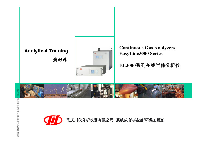
/环保工程部压力传感器1压力传感器2O2传感器1或2个分析模块电源IO板AMC控制器流量传感器1必须与一个分析模块共同选用其它部件可选EL3000的分析模块可以灵活的组合:Uras26 + Mangos206Uras26 + Caldos27Mangos206 + Caldos27Uras26 + O2传感器所有的分析模块都与AMC控制器通讯AMC=Analyzer Module ControllerEL3000的分析模块以及压力传感器、流量传感器都有一个具有单独序列号的SSI板SSI=Sensor Specific Interface信号处理电路显示驱动电路及控制软件机箱电源模块线性偏差: ≤1%FS重复性: ≤0.5%FS零点漂移: ≤1%FS/7d灵敏度漂移: ≤1%测量值/7d输出波动: ≤0.2%FS检测极限: ≤0.4%FS启动时间:≤30min(无恒温)或≤2h(有恒温)响应时间:T90 ≤2.5S(气室长度为175mm,样气流量为60L/h)流量范围: 20-100L/h入口压力: 2-500hPa(即: 0.2kPa-50kPa)出口压力: 大气压力样气组份: 不含高腐蚀性气体(如Cl2,HCl)和机械杂质即水等线性偏差: ≤0.5%FS重复性: ≤1%FS零点漂移: ≤0.1%FS/7d灵敏度漂移: ≤0.1%O2/7d 或≤1%测量值/7d输出波动: ≤0.5%FS检测极限: ≤1%FS启动时间:≤1h响应时间:T90 ≤4S(从N2变化到空气浓度,样气流量为90L/h)流量范围: 30-90L/h入口压力: 2-100hPa(即: 0.2kPa-10kPa)出口压力: 大气压力样气组份: 不含高腐蚀性气体(如Cl2,HCl,HF)和机械杂质即水等线性偏差: ≤1%O2重复性: ≤0.5%FS零点漂移: 能长期稳定于零点灵敏度漂移: ≤1%O2FS/7d输出波动: ≤0.2%FS检测极限: ≤0.4%FS流量范围: 20-100L/h入口压力: 2-500hPa(即: 0.2kPa-50kPa)出口压力: 大气压力样气组份: 不含H2S、氯化物、氟化物、重金属、气雾剂(烟雾剂)等24V压力传感器1流量传感器1其它模块TCT RS232 接口ECT以太网接口电源输入Profibus模板模拟量模板OK操作设置返回维护CalibrationCalibration菜单Manual CalibrationAutomatic Calibration按手动ESC 返回ESC返回返回按键选择需要校准的组份CO,键移动光标, 修改参数返回ESC返回按Manual Calibration手动ESC 返回ESC返回ESC返回按键移动光标, 修改参数ESC返回ESC返回按Automatic CalibrationManual Calibration返回Calibration返回自动校准启动功能不要随意启动,一旦选择键后,即刻执行自动校准,在没有外菜单模式(ESC 返回ESC返回按Measurement RangesCalibration Data校准参数按Device SettingsESCESC 返回Measurement RangesCalibration Data校准参数Device SettingsESC返回Autocal.SettingsESC返回Purge Times吹洗时间Autocal. ControlESC按按返回ESC返回键选择每一个测量组份COMeasurement RangesCalibration Data校准参数Device Settings ESC返回ESC返回Autocal.Settings Test Gas Set Points ESC返回按键选择每一个测量组份EnglishMeasurement RangesCalibration Data校准参数按Device Settings 返回返回网络设置LanguageEthernetESC Date/Time 按ESC返回按返回按ESC返回返回校准复位Atmospheric PressureCalibration ResetESC按菜单Maintenance SwitchBasic SettingsDiagnosisESC 返回按返回上下移动光标选择复位组份ESC返回按ESC返回仪器信息Device TestDevice infoESC返回按菜单Maintenance SwitchBasic SettingsDiagnosis Device info 返回按上下移动光标份按Device Status ESC返回显示屏测试I/O TestDisplay TestKeypad TestESC返回Drift indicationStatus messages Status messages按返回ESCStatus messages 返回ESC修改数字滤波时间常数配置信号保持报警值设定安装中文语言包配置自动校正参数配置模拟输出点配置数字I/O点查看分析仪中已存在模块的配置ECT带网卡的电脑点对点连接带RJ45头的网线(1-3,3-1,2-6,6-2) ECT软件器有限公司系统成套事业部/环保工程部谢谢大家!重庆川仪分析仪器有限公司系统成套事业部/环保工程部。
ABB EL3020气体分析仪 校验

校验时,先校验零点后校验量程。
一、校验零点1、ABB分析仪预热12小时以上。
2、将启动开关打到OFF,使系统停止吹扫和采样。
3、采用高纯氮气。
4、将高纯氮气接到箱体的零点气入口位置。
5、五通切换阀打到校零位置。
6、将报警流量计关掉。
7、打开氮气罐阀门。
8、调整氮气罐减压阀,使阀后压力保持在0.01MPa。
9、打开报警流量计,使其流量保持在60L\H,使用零点气将分析仪气室吃扫1~2分钟后再进行零点校验。
10、点击ABB面板上的(1)OK------操作------校准------手动校准------零点------OK------CO------OK------输入校验的标准值(+2ppm)------OK(确认输入的数据)------OK (保存校准值)------退出,(2)OK------操作------校准------手动校准------零点------OK------O2----OK------输入校验的标准值(0 VOL%)-------OK(确认输入的数据)------OK (保存校准值)------退出。
11、校验完毕,待系统保存完毕后(状态图标消失)先关高纯氮气罐阀门,再松掉氮气罐减压阀,把高纯氮气罐放回原位,五通切换阀打到采样位置。
二、校验量程(一)CO的量程校验1、ABB分析仪预热12小时以上2、将启动开关打到OFF,使系统停止吹扫和采样。
3、采用厂家提供的CO标气。
4、将CO标气接至箱体的标准气入口1位置。
5、五通切换阀打到校正1位置。
6、将报警流量计关掉。
7、打开CO标气罐阀门。
8、调整CO标气罐减压阀,使阀后压力保持在0.01MPa。
9、打开报警流量计,使其流量保持在60L\H,使用CO标气将分析仪气室吃扫1~2分钟后再校验量程。
10、点击ABB面板上的(1)OK------操作------校准------手动校准------量程------OK------CO------OK------输入校验的标准值(标气罐铭牌上的数值)------OK(确认输入的数据)------OK(保存校准值)------退出。
ABB分析仪EL3000系列和AO2000系列选型
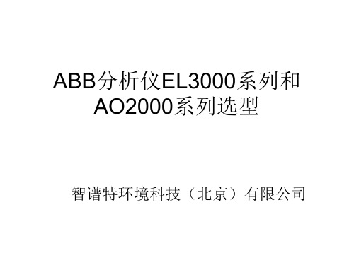
EL3020完整的模块化部件构架
EL3020分析模块表格
模块名称 原理 可测气体 量程(ppm) 备注
O2模块
Uras26
电化学
红外
O2
SO2 NO
0—100
0—100~5000 0—150 ~5000
必须跟一个分析模块共同选用,比如Uras26、 Limas23。
最多可测4钟组分。
CO
CO2 N2O CH4
EL3020完整的模块化部件构架
1、压力传感器1; 2、压力传感器2; 3、I/O板及通讯接口模块; 4、电源; 5、AMC控制器:分析模块控制器,所有的模块都要跟AMC控制器通讯; 6、O2模块:电化学氧模块,必须跟其他分析模块配合选用,比如Uras26、 Limas23; 7、Uras26:红外线分析模块,可测SO2、NO、CO、CO2、N2O、CH4; 8、Magnos206:氧分析模块,可测过程气体中的O2; 9、ZO23:氧分析模块,氧化锆原理,只能单独使用,可测纯净气体(如N2、 Ar)中的O2; 10、Caldos27:热导分析模块,可测不同热导率的对称性混合气体中一种,比 如Ar中的H2; 11、Limas23:紫外光度计分析模块,可测SO2、NO、NO2; 12、流量传感器(可选)。
0—100 ~5000
0—100 ~5000 0—100 ~5ZO23 Caldos27 Limas23
顺磁
氧化锆 热导 紫外
O2
O2 Ar中的H2 SO2 NO NO2
0—1 ~ 25%V
0—1 ~25%V 0—1%V 0—100~5%V 0—50~500 0—50~500
abb分析仪el3000系列和ao2000系列选型abb接触器选型手册abb电机选型手册abb选型手册abb断路器选型手册abb变频器选型手册abb软启动器选型abb隔离开关选型手册abb热继电器选型手册abbacs800选型手册
- 1、下载文档前请自行甄别文档内容的完整性,平台不提供额外的编辑、内容补充、找答案等附加服务。
- 2、"仅部分预览"的文档,不可在线预览部分如存在完整性等问题,可反馈申请退款(可完整预览的文档不适用该条件!)。
- 3、如文档侵犯您的权益,请联系客服反馈,我们会尽快为您处理(人工客服工作时间:9:00-18:30)。
Smallest Measurement Range 0– 100 ppm 0– 100 ppm 0– 150 ppm 0– 100 ppm 0– 100 ppm 0– 100 ppm
Measurement Range Limits 0–500 (NO: 750) / 1000 / 3000 ppm, 0–1/ 3 / 10 / 30 / 100 Vol.-% The measurement ranges are freely adjustable within a range ratio of max. 1: 5. An individual measurement range can be factory-set on request. Measurement ranges should not be set within ignition limits.
The integral gas feed (option) is available in two versions. It either includes
• the micro-filter and flow sensor modules
• or the micro-filter, solenoid valve, pump, coarse filter, capillary tube and flow sensor modules.
Associated Gas Effect / Cross Sensitivity The knowledge of the sample gas composition is necessary for the analyzer configuration. Selectivity measures to reduce associated gas effect (optional): Incorporation of interference filters or filter cells, internal electronic cross-sensitivity correction for one sample component by other sample components measured with the gas analyzer.
required
Contents
Overview of the Gas Analyzers Infrared Photometer Uras26 Oxygen Analyzer Magnos206 Thermal Conductivity Analyzer Caldos27 Electrochemical Oxygen Sensor Integral Gas Feed General Data Electrical Connections Gas Connections Certifications
eliminating the need for test gas cylinders
Customizable analog outputs, digital inputs and outputs Modbus interface
Integral gas feed (optional) Simple menu-driven operator interface Clear-text status messages Configuration of rarely required functions with included
• Magnos206 oxygen analyzer for the measurement of O2 in process gas or in N2
• Caldos27 thermal conductivity analyzer for the measurement of binary gas mixtures with different thermal conductivity e.g. Ar in O2, H2 in Ar, CH4 in N2
configuration program
Housing version for 19-inch rack mounting (3 height units,
IP20)
Modular design for ease of service Self-monitoring function indicates when maintenance is
Up to five measurement components per gas analyzer Suitable for measuring flammable gases Automatic calibration including pump and valve control Simplified calibration with air or integral calibration cells
Temperature Effect Ambient temperature in permissible range – At zero-point: ≤ 2 % of span per 10 °C – On sensitivity without thermostat: ≤ 3 % of measured value per 10 °C – On sensitivity with thermostat (optional): ≤ 2 % of measured value per 10 °C Thermostat temperature = 55 °C
The analyzer has one physical measurement range per sample component. The smallest measurement ranges are shown in the following table.
Sample Component CO CO2 NO SO2 N2O CH4
EasyLine Continuous Gas Analyzers Model EL3020
Data Sheet
10/24 4.10 EN November 2005
Detectors with different measurement principles for
numerous process and emission monitoring applications
• Electrochemical oxygen sensor for the measurement of O2
The electrochemical oxygen sensor can only be used in combination with the Uras26 infrared photometer.
10/24-4.10 EN November 2005
EasyLine EL3000 Series Data Sheet
3
Infrared Photometer Uras26
Measurement Principle
Non-dispersive infrared absorption in the λ = 2.5–8 µm wavelength range
Repeatability ≤ 0.5 % of span
Zero Drift ≤ 1% of span per week
Sensitivity Drift ≤ 1% of measured value per week
Output Fluctuation (2 σ) ≤ 0.2 % of span at electronic T90 time (static / dynamic) = 5 / 0 sec
Note Regarding the Performance Characteristics of the Analyzers
The performance characteristics of the analyzers have been determined according to the international standard IEC 1207-1: 1994 “Expression of performance of gas analyzers”. They are based on N2 as the associated gas. Compliance with these characteristics when measuring other gas mixtures can only be assured if their composition is known.
Photometer to measure up to 4 components with 1 or 2 beam paths and 1 or 2 receivers per beam path in one gas path or two separate gas pas and Measurement Ranges
Stability
The following data apply only if all influence factors (e.g. flow rate, temperature, atmospheric pressure) are constant.
Linearity Deviation ≤ 1% of span
as well as the integrated I/O modules depending on the functional range and order
• Analog output module with 2 analog outputs,
• Digital I/O module with 4 digital inputs and 4 digital outputs and
