shimano-SL-M751前拨专业技术说明
SHIMANO 变速器(手变)说明书

(English)DM-ST0001-05Dealer's ManualMTB RAPIDFIRE Plus ST-M4000ST-M4050ST-T4000ST-T3000ST-M370EZ-FIRE Plus ST-EF65ST-EF51ST-EF51-AST-TX800ST-EF41ST-EF40ROADTiagraST-4600ST-4603SORAST-3500ST-3503 SHIMANO Claris ST-2400ST-2403 SHIMANO 2300 ST-2300ST-2303 TourneyST-A070ST-A073Non-SeriesST-R460ST-R350ST-R353ST-R240ST-R243•This dealer's manual is intended primarily for use by professional bicycle mechanics.Users who are not professionally trained for bicycle assembly should not attempt to install the components themselves using the dealer's manuals.If any part of the information on the manual is unclear to you, do not proceed with the installation. Instead, contact your place of purchase or a local bicycle dealer for their assistance.•Make sure to read all instruction manuals included with the product.•Do not disassemble or modify the product other than as stated in the information contained in this dealer's manual.•All dealer's manuals and instruction manuals can be viewed on-line on our website ().•Please observe the appropriate rules and regulations of the country, state or region in which you conduct your business as a dealer.•When installing components, be sure to follow the instructions that are given in the instruction manuals.It is recommended to use genuine Shimano parts only. If parts such as bolts and nuts become loose or damaged, the bicycle may suddenly fall over, which may cause serious injury.In addition, if adjustments are not carried out correctly, problems may occur, and the bicycle may suddenly fall over, which may cause serious injury.•Be sure to wear safety glasses or goggles to protect your eyes while performing maintenance tasks such as replacing parts.•After reading the dealer's manual thoroughly, keep it in a safe place for later reference.Be sure to also inform users of the following:•The ST-EF65/ST-EF51/ST-EF51-A (4-finger brake levers) brake levers are equipped with a mechanism to make them compatible with V-BRAKE brakes, which contain a power modulator, cantilever and roller brakes.If the incorrect mode is selected it may cause either excessive or insufficient braking force to occur, which could result in dangerous accidents.Be sure to select the mode in accordance with the instructions given in the table below.C/R positionVVRCC R: Mode position for compatibility with cantilever brakes: Mode position for compatibility with roller brakesV positionVVRCC Rode position for compatibility with V-BRAKE brakeswith power modulatorUse the brake levers with mode switching mechanism in the combinations given above.•Each bicycle may handle differently depending on the product. Therefore, it is important to completely understand and get used to the operation of your bicycle's brake system (including brake lever pressure and bicycle control characteristics).Improper use of your bicycle's brake system may result in a loss of control or a fall, which could lead to severe injury. For proper operation please consult a professional bicycle dealer, or read the owner’s manual. It is important to ride your bicycle and practice braking operation and other basic features, etc.•If the front brake is applied too strongly, the wheel may lock and the bicycle may fall forward, and serious injury may result.•Always make sure that the front and rear brakes are working correctly before riding the bicycle.•The required braking distance will be longer during wet weather. Reduce your speed and apply the brakes early and gently.•If the road surface is wet, the tires will skid more easily. If the tires skid, you may fall off the bicycle. To avoid this, reduce your speed and apply the brakes early and gently.NOTEBe sure to also inform users of the following:•Be sure to keep turning the crank during gear shifting.•Read the dealer's manuals for the front derailleur, rear derailleur, and brake.•Products are not guaranteed against natural wear and deterioration from normal use and aging.•For maximum performance we highly recommend Shimano lubricants and maintenance products.For Installation to the Bicycle, and Maintenance:•When installing the top route type, choose a frame that has three outer casing holders as shown in the illustration at right.Outer casing holder•Use an outer casing which still has some length to spare even when the handlebars are turned all the way to both sides. Furthermore, check that the shifting lever does not touch the bicycle frame when the handlebars are turned all the way.•Use the specified cable and cable guide for smooth operation.•Grease the inner cable and the inside of the outer casing before use to ensure that they slide properly.•Using a frame with internal cable routing is strongly discouraged as it has tendencies to impair the SIS shifting function due to its high cable resistance.•A special grease is used for the gear shifting cable. Do not use premium grease or other types of grease, otherwise they may cause deterioration in gear shifting performance.•If gear shifting adjustments cannot be carried out, check that the rear fork ends are aligned. Also, check if the cable is lubricated and if the outer casing is not too long or short.The actual product may differ from the illustration because this manual is intended mainly to explain the procedures for using the product.MTBInstallation to the handlebarThe tools and tightening torque vary depending on the product. Tighten with a tightening torque that matches the tool size.* Use a handlebar grip with a maximum outer diameter of ɸ32 mm.5 mm Allen key3 mm Allen key< ST-TX800, ST-EF41 >3 mm Allen keyInstallation of the brake cable* Install it as shown in the figure.123ROADInstallation to the handlebarSecure the assembly with the clamp bolt on the outside of the bracket.Pull the bracket cover back and use a 5 mm Allen key to tighten the bolt.Use a handlebar grip with a maximum outer diameter of ɸ 32 mm.Installation of the brake cableROADCable used* Use a cable which still has some length to spare even when the handlebars are turned all the way to both sides.* For information on how to install the brake cable, refer to brake dealer's manual.1.Tilt the lever in (as when shifting) to make it easier to pass the cable through the cable hook.2.Pass the inner cable through.Note:Do not wipe off the grease on the inner cable.Do not let dust adhere on the inner cable.3. Finally, wrap the handlebar with the handlebar tape.MTBCable used(1)Cutting the outer casingWhen cutting the outer casing, cut the end opposite to the end with the marking.After cutting it, make the end round so that the inside of the hole has a uniform diameter.Attach the same outer end cap to the cut end of the outer casing.< Rear lever >1. Set lever (B) to the top position.2. Check the top position on the indicator and install the cable.3.4. Run the inner cable through the outer casing.If the cable hook does not align with the shifting cable hole, press lever (B) again until it does, and then install the cable.< Front lever >Operate lever (B) 2 or more times, check on the indicator that the low position is correct, and then secure the inner cable.Lever (B)1. 2.2< Cable adjuster >The adjustment margin for the cable adjuster is five turns from its fully-tightened position.The adjuster is tightened to the point where it is 1 turn loose of the fully-tightened state.* W 1.* Insert a thin bar-shaped object to remove the outer support spacer.2. Install the outer casing holder cap (sold separately).(sold separately)Note:Install after the adjustment bolt is tightened.The adjustment range for the adjustment bolt is six full turns.2. Pass the inner cable through, and set the outer casing.* Use an outer casing which still has some length to spare even when the handlebars are turned all the way to both sides.Confirm:Make sure the outer casing is firmly set in the outer stopper.Lever stroke adjustmentLever stroke adjustment can be carried out in the following ways.For the tools to be used and adjustment point (s), refer to the table below.(A) Clockwise: The lever strokebecomes smaller.(B) Counterclockwise: The lever strokebecomes larger.When using the reach adjustment block (Pad spacer)Note:When installing the 8-degree reach adjustment block, use an anatomic-type handlebar. If a round-type handlebar is used, the cable stroke may become too short and this can result ininsufficient braking force.Anatomic typeRound type< ST-4600 / ST-4603 / ST-3500 / ST-3503 / ST-2400 / ST-2403 / ST-R460 / ST-R350 / ST-R353 >Pad spacers (A)4°Pad spacers (A) + (B)8°To increase the lever strokeRemove the pad spacer (A) and install the bump rubber.To decrease the lever strokeInsert pad spacer (B) as far as it will go and so that the protrusions fit into the holes in pad spacer (A).* Apply a small amount of grease to the protrusions when installing the pad spacer and the bump rubber.< ST-2300 / ST-2303 >To reduce the reach, remove the bump rubber and replace it with theaccessory pad spacer (two available types: 4° and 8°).8°Replacement method 1. Remove the bump rubber.2. Apply a thin layer of grease to the two protrusions on the pad spacer.3. Press-fit the pad spacer so that the protrusion go as far in as possible.Bump rubberAdjusting the inner cableWhen the cable adjuster is providedThe adjustment margin for the cable adjuster is five turns from its fully-tightened position.The adjuster is tightened to the point where it is 1 turn loose of the fully-tightenedstate.Replacing the inner cable< In the case of a type with a screw-on cover >1. Set lever (B) to the smallest gear/sprocket.3. Pull out the inner cable and install a new inner cable.< In the case of a type with a wire end hooking cap >1. Set lever (B) to the smallest gear/sprocket.2. Remove the wire end hooking cap and install a newinner cable.nd hooking capWire end hooking capScrewdriver #2•For information on how to replace the shifting cable, refer to "Installing the shifting cable".•For information on how to replace the shifting cable with the one without a cable adjuster, refer to "Installing the shifting cable/Cable adjuster."Bracket and lever disassembly* The illustration shows the right-hand lever.< ST-4600 / ST-4603 / ST-3500 / ST-3503 / ST-2400 / ST-2403 / ST-R460 / ST-R350 / ST-R353 >1. First use the Shimano original tool (sold separately) to remove the E-ring. Use part (B) of the Shimano original tool (2) to alignthe E-ring with the direction of removal. Next, set part (A) against the E-ring and remove the E-ring.* Tourney is not equipped with an E-ring.Y6RT66000(1)Shimano original E-ring removal toolWhen removing the E-ring, it may suddenly spring out, make sure there are no persons or objects around before removing it.2. Insert an Allen key or similar tool into the lever axle hole, tap it gently with a plastic hammer to push out the lever axle, whichdisassembles it into the bracket body and the lever body.Bracket bodyLever axleLever bodyNote:Always be sure to remove the lever axle in this direction. If it is removed in the opposite direction, it may damage the bracket body.< ST-2300 / ST-2303 / ST-A070 / ST-A073 >1. First use a 2 mm Allen key to remove the bolt.2. Insert an Allen key or similar tool into the lever axle hole, tap it gently with a plastic hammer to push out the lever axle, whichdisassembles it into the bracket body and the lever body.Lever bodyNote:Always be sure to remove the lever axle in this direction. If it is removed in the opposite direction, it may damage the bracket body.Replacing the return spring< ST-3500 / ST-3503 / ST-2400 / ST-2403 / ST-R350 / ST-R353 > 1. With the spacer fitted in the return spring, push the tip ofthe return spring into the hole in the bearing member, and press in the shaft bushing.* Note that the left and right return springs are different.Set the end of the spring in the hole in the bearing member.HoleSpacer< ST-2300 / ST-2303 >1. Set the return spring on the hole in the bearing member ofthe lever body.* Note that the left and right return springs are different.Set the end of the spring inthe hole in the bearingmember.HoleAssembling the bracket body and lever body< ST-4600 / ST-4603 / ST-R460 >1.Return springNotch2. Align the stud holes, and then set the Shimano original tool(1) in the position shown in the illustration to press-fit the lever axle.•The correct direction for the lever axle is for the E-ring groove to face up.•Check that the surface of the bracket body is flat so theE-ring of the lever axle can fit into the groove properly.E-ring grooveShimano original E-ring removal tool (1):Y6RT660003. Remove the Shimano original tool (1), and then use theShimano original tool (2) to install the E-ring.< ST-3500 / ST-3503 / ST-2400 / ST-2403 / ST-R350 / ST-R353 >1.Set the Shimano original installation tool for the return spring.Shimano original installation tool for the return spring (TL-ST03)2. Align the stud holes, and then set the Shimano original tool(1) in the position shown in the illustration to press-fit the lever axle.•The correct direction for the lever axle is for the E-ring groove to face up.•Check that the surface of the bracket body is flat so the E-ring of the lever axle can fit into the groove properly.Shimano original E-ring removal tool (1):Y6RT660003. Shimano original tool (2) to install the E-ring.Shimano original E-ring removal tool (2):4. with pliers.5. functions properly.Shimano original installation tool for the return spring< ST-2300 / ST-2303 / ST-A070 / ST-A073 >1. Set the Shimano original installation tool for the return spring.Shimano original installationtool for the return spring(TL-ST03)2. Align the stud holes, and then press-fit the lever axle in the position shown in the illustration.Fixed by a lever fixing screwThe correct position is for the round hollowon the lever axle to be aligned with theTightening torque:1 -2 N·m {9 - 17 in. lbs.}3. Remove the Shimano original installation tool for the returnspring with pliers.4. Finally, check that brake operation is normal and the returnspring functions properly.Shimano originalinstallation tool for thereturn springReplacing the bracket coverThe tabs on the bracket cover each fit to a matching slot on thebracket.•Wipe a little rubbing alcohol inside the bracket cover to make installation easier.Please note: specifications are subject to change for improvement without notice. (English) © Feb. 2015 by Shimano Inc. HTR。
捷安特运动车前拨和后拨安装与调整
捷安特运动车前拨和后拨安装与调整前拨和后拨安装与调整说到运动自行车,我们就不得不谈谈前后变速器,作为运动自行车不可或缺的组件,变速器的地位还是非常重要的. 试想用一辆单飞车去爬天文台的大坡,我想更多的车友还是愿意找一辆变速车的吧! 既然变速器对于运动车如此重要,那么了解变速器的调整也就变得十分重要了.一辆变速精准的运动车会给你的骑行带来更多的乐趣. 下面我们就来谈谈运动车的变速器吧: 运动车的变速器一共由这几部分组成:指拨 (用于调整变速的档位,通常有两个,分别控制前后拨链器) ,前拨 (用于调整链条在牙盘上的位置,通常有3个档位) ,后拨 (用于调整链条在飞轮上的位置,通常有8档和9档之分),变速内线 (用于链接指拨和前后拨)变速外线管 (用于引导和保护内线). 了解了变速套件的组成,下面我们来看看个部分的安装位置: 指拨: 通常安装在把横上,方便双手的控制.前拨: 通常安装在车架的立管上,位于牙盘的上方.后拨: 通常安装在车架的右后方的勾爪上,有固定的螺孔.变速系统的安装注意事项: 指拨: 前拨在左手,后拨在右手. 前拨: 外拨链片高过牙盘的最高齿约2-3mm ,一般在前拨首次安装的时候都会在拨链片上有安装校对的贴纸,安装到位后即可撕去.后拨: 注意将后拨张力调整螺丝放置在勾爪的上方,以免顶坏勾爪.外线管: 视不同的车架进行安装,通常前拨线由左到右进入,后拨由右到左进入.变速内线: 首先穿过指拨,经由变速外线,分别到达前拨和后拨. 下面让我们来了解一下各个组件吧: 首先是前拨: 前拨上有两颗定位螺丝,一个标示为H ,一个表示为L ,分别代表了前拨的高低两个限位, L ---代表了低限位,也就是前拨在最小盘时所在的位置,通常当链条处在前面最小盘,后面最大飞轮的时候,链条距离前拨的内拨链片大约2-3mm. H ---代表了高限位,也就是前拨在最大盘时的位置,通常当链条处在前面最大盘,后面最小飞轮的时候,链条距离前拨的外拨链片大约2-3mm.接着是后拨: 在后拨的后方一共有3颗螺丝和一个微调螺丝. 由上至下分别为: 后拨张力调整螺丝, 高速限位螺丝 H ,低速限位螺丝 L ,和后拨线张力微调旋钮. 后拨张力调整螺丝: 用于调整后拨的上导轮与飞轮的间距.向内旋入时,可使导轮与飞轮的间距加大,反之减小高速限位螺丝: 用于调整后拨在最小飞轮片时的位置,通常保持上导轮的中心线,与最小飞轮片的外沿在一条直线上. 低速限位螺丝: 用于调整后拨在最大飞轮片时的位置,通常保持上导轮的中心线,与最大飞轮片的外沿在一条直线上. 后拨线张力微调旋钮: 用于对后拨的位置进行微调,当变速时飞轮上链不畅时,逆时针调整微调旋钮,当下链不畅时,顺时针调整微调旋钮.下面我们来详细的介绍一下变速系统的安装和调试. 我们以初装车安装变速系统为例: 第一步: 将指拨,前拨,后拨,以及线管安装到位,检查指拨是否都处于最小档,左手在1挡,右手在8或9档,没有档位显示的指拨,要确保红色的指针都处在最内侧. 第二步: 调整后拨限位,在没有安装链条的情况下,是比较容易调整后拨限位的,这时比较容易确定导轮中心线与最大和最小飞轮的位置.确保上导轮的中心线在H位上处于最小飞轮的外沿,而在L位上的时候处于最大飞轮的外沿.将后变速线微调螺丝先往顺时针方向全部旋入,再以逆时针方向回旋两圈,以确保足够的微调行程.第三步: 调整前拨的高低位置,用手向外拉动前拨,观察牙盘的最高齿与前拨外拨链片的间距,确保间距在2-3mm左右.从上方观察前拨,确保前拨的外拨链片与牙盘的盘片平行.第四步: 将前拨线与后拨线固定好,用左手抓紧后拨,用力拉动位于车架上管上的后变速线,确保所有的线帽都收紧到位,随后使用同样的方法,收紧前拨的线管.接着松掉前后内线.第五步: 将链条安装到位. 第六步: 将后拨线重新上紧,变速至最大飞轮片,调整前拨的L螺丝,让前拨的内拨链片距离链条的内侧约2-3mm,随后上紧前拨线,将链条再调至最小飞轮和最大牙盘,调整前拨H螺丝,使前拨的外拨链片距离链条外侧2-3mm..此时,变速系统安装到位. 对于已经安装好,并骑行一段时间后出现变速不准的运动车,在进行调试的时候,首先要确认前后拨的限位是否正常,车架后勾爪有没有向内或向外变形,变速内线是否过于松动.前拨是否与牙盘平行,高度是否合适. 在以上几项检查确认无误之后: 1: 如果后拨上链不畅,则逆时针旋动后拨线微调螺丝,直至上链顺畅. 2: 如果后拨下链不畅,则顺时针旋动后拨线微调螺丝,直至下链顺畅. 3: 如果前拨上链不畅,则逆时针旋动位于左手指拨上的前拨线微调螺丝,直至上链顺畅. 4: 如果前拨下链不畅,则顺时针旋动位于左手指拨上的前拨线微调螺丝,直至下链顺畅.每次旋动的幅度大约在4分之1,或半圈.在指拨上各有一个微调螺丝,可以用来在骑行的过程中,不用下车就可以对前后的变速进行调节.shimano的后拨上是有一个微调螺丝的,但是sram的后拨就没有了,只可以在指拨上进行调节. 这是因为各个厂商的设计不懂导致的,但是调整变速的方法是一样的没有任何的区别.这里介绍的主要是山地车的变速器安装和调整,相对的还有公路车的变速系统,从安装的角度来说,山地和公路的安装没有太多的区别,各个限位的调整也是一样的,只是公路车的指拨上是没有微调螺丝的,通常公路的微调螺丝是在车架的下管上的,调整的方法与山地一样.还要说说的就是为什么回出现变速不准的情况呢??1: 车子在摔倒的过程中,变速器遇到了撞击,导致安装位置的偏移,从而发生变速不准.2:发力时的强行变速,导致链条将变速器挤压变形,导致变速不准.3:安装时没有预拉内线,在后来的骑行中,变速内线松动,导致变速不准.4:长时间的没有清理变速内外线管,导致堵塞,导致内线无法顺畅的来回拉动,从而变速不准.以上的这些情况,都会引起变速的不精确.时常的保养和调试,把车当做是你的好朋友,爱惜自己的运动自行车,关心他们,让他成为你生活中的一部分,我相信你自行车朋友能够让你获得更多的乐趣,让我们享受骑行的乐趣,去经历更多的人生旅途吧!!。
禧玛诺公路车变速手柄说明书
Manual del distribuidorDM-ST0001-05(Spanish)CARRETERATiagraSORASHIMANO ClarisSHIMANO 2300TourneySin serieMTBRAPIDFIRE PlusEZ-FIRE PlusST-M4000ST-M4050ST-T4000ST-T3000ST-M370ST-EF65ST-EF51ST-EF51-A ST-TX800ST-EF41ST-EF40ST-4600ST-4603ST-3500ST-3503ST-2400ST-2403ST-2300ST-2303ST-A070ST-A073ST-R460ST-R350ST-R353ST-R240ST-R243•Este manual del distribuidor está dirigido principalmente a mecánicos de bicicletas profesionales.Los usuarios que no hayan recibido formación profesional en el montaje de bicicletas no deberán intentar la instalación de componentes usando los manuales del distribuidor.Si tiene dudas en relación con cualquier información de este manual, no proceda con la instalación. Por el contrario, póngase en contacto con el comercio donde hizo la compra o un distribuidor local de bicicletas para solicitar asistencia.•Lea todos los manuales de instrucciones incluidos con el producto.•No desmonte o modifique el producto más allá de lo permitido en la información de este manual del distribuidor.•Puede consultar online todos los manuales del distribuidor y manuales de instrucciones en nuestro sitio web().•Cumpla con la normativa y las reglamentaciones del país o región donde ejerce su trabajo de distribuidor.•D urante la instalación de componentes, asegúrese de seguir las indicaciones de los manuales de instrucciones.S e recomienda utilizar exclusivamente piezas originales de Shimano. Si piezas como tornillos y tuercas se aflojan o se deterioran, la bicicleta puede desmontarse repentinamente, provocando lesiones corporales graves.A demás, si los ajustes no se realizan correctamente, podrían producirse algunos problemas y la bicicleta podría desmontarse repentinamente, provocando lesiones corporales graves.•U tilice gafas de seguridad para proteger los ojos mientras realiza tareas de mantenimiento, como la sustitución de piezas. •D espués de leer detenidamente el manual del distribuidor, guárdelo en un lugar seguro para consultas futuras.A simismo, asegúrese de informar de lo siguiente a los usuarios:•L as palancas de freno ST-EF65/ST-EF51/ST-EF51-A (palancas de freno para 4 dedos) están equipadas con un mecanismo para hacerlas compatibles con los FRENOS V con modulador de potencia o frenos cantilever y de rodillo.S i se selecciona un modo incorrecto puede producirse que la fuerza de frenado sea excesiva o insuficiente, lo que podría causar accidentes peligrosos.A segúrese de seleccionar el modo de acuerdo con las instrucciones que se dan en la tabla de la derecha.P osición C/RVVRCC Rosición de modo para compatibilidad con frenososición de modo para compatibilidad con frenosP osición-VVVRCC Rosición de modo para compatibilidad con FRENOS Vcon modulador de potenciatilice las palancas de freno con el mecanismo de cambio de modo en las combinaciones especificadas anteriormente.•Cada bicicleta puede funcionar de forma diferente dependiendo del producto. Por lo tanto, es importante entender y acostumbrarse al funcionamiento del sistema de frenado de la bicicleta (incluyendo la presión de la maneta del freno y las características de control de la bicicleta). Un uso inadecuado del sistema de frenos podría hacerle perder el control o caer, con la posibilidad de sufrir lesiones de gravedad. Para conseguir un funcionamiento óptimo consulte a su distribuidor de bicicletas o el manual del propietario. Es importante probar la bicicleta y el funcionamiento de los frenos, así como otras funciones básicas, etc.•Si el freno delantero se aplica demasiado fuerte, la rueda puede bloquearse y la bicicleta puede caer hacia delante y causarle lesiones graves.•Asegúrese siempre de que los frenos delanteros y traseros funcionan correctamente antes de montar en la bicicleta.•La distancia de frenado necesaria aumenta con el suelo mojado. Reduzca su velocidad y aplique los frenos de manera suave y anticipada.•Si la superficie de la carretera está mojada, las cubiertas patinarán con mayor facilidad. Si las cubiertas patinan, puede producirse una caída. Para evitarlo, reduzca su velocidad y aplique los frenos de manera suave y anticipada.NOTAAsimismo, asegúrese de informar de lo siguiente a los usuarios:•Asegúrese de mantener la biela girando durante el funcionamiento del cambio. •Lea los manuales del distribuidor del desviador, el cambio y el freno.•Los productos no están garantizados contra el desgaste natural y el deterioro resultante del uso normal y el envejecimiento.Para la instalación en la bicicleta y el mantenimiento:•Cuando monte el tipo de recorrido superior, seleccione un cuadro que disponga de tres soportes de funda exterior como se indica en la ilustración de la derecha.•Utilice una funda exterior que tenga la suficiente longitud para permitir girar el manillar completamente a ambos lados. Además, verifique que la maneta de cambio no toca el cuadro de la bicicleta cuando se gira el manillar completamente. •Utilice el cable especificado y una guía de cable para lograr un funcionamiento suave.•Engrase el cable interior y el interior de la funda exterior antes de utilizarlos, para garantizar que deslizan correctamente. •Se desaconseja el uso de un cuadro con tendido de cable interno, ya que tiende a impedir el funcionamiento del cambio SIS debido a la alta resistencia del cable.•Para el cable del cambio se utiliza una grasa especial. No utilice grasa de alta calidad o de otros tipos, porque podría deteriorar el funcionamiento del cambio.•Si no se pueden realizar ajustes en el cambio, compruebe que los extremos de la horquilla trasera están alineados. Compruebe también si el cable está lubricado y si la funda exterior es demasiado larga o demasiado corta.El producto real puede diferir de la ilustración, ya que este manual está concebido básicamente para explicar los procedimientos de uso del producto.Soporte de la funda exteriorMTBInstalación en el manillarLas herramientas y los pares de apriete varían dependiendo del producto. Realice el apriete a un par adecuado para el tamaño de la herramienta.* Utilice un puño de manillar con un diámetro exterior no mayor de 32 mm.Llave Allen de 5 mm Llave Allen de 3 mm< ST-TX800, ST-EF41 >Llave Allen de 3 mmInstalación del cable de freno* Móntelo tal como se muestra en la figura.123CARRETERAInstalación en el manillarSujete el conjunto con el tornillo de sujeción sobre la parte externa del soporte.Tire hacia atrás de la tapa del soporte y utilice una llave Allen de 5 mm para apretar el tornillo.Utilice un puño de manillar con un diámetro exterior no mayor de 32 mm.Instalación del cable de frenoCARRETERACable usado* Utilice un cable que tenga la suficiente longitud para poder girar el manillar completamente a ambos lados.* Para obtener información sobre cómo instalar el cable del freno, consulte el manual del distribuidor del freno.1. Incline la palanca hacia dentro (como cuando se acciona el cambio) para facilitar el paso del cable a través del gancho del cable.2. Pase el cable interior a través.Nota:No limpie la grasa del cable interior.No permita que se adhiera polvo al cable interior.3. Finalmente, envuelva el manillar con la cinta para manillar.MTB(1)Corte de la funda exteriorAl cortar la funda exterior, corte el extremo opuesto al extremo marcado.Después de cortarla, redondee el extremo para que el interior del orificio tenga un diámetro uniforme.Coloque el mismo terminal exterior para cortar el extremo de la funda exterior.< Palanca trasera >1. Coloque la palanca (B) en la posición superior.2. Compruebe la posición superior en el indicador y monte el cable.3.4. Pase el cable interior a través de la funda exterior.Si el gancho del cable no se alinea con el orificio del cable del cambio, presione la palanca (B) de nuevo hasta que lo haga y, a continuación, instale el cable.Confirmar: Asegúrese de que el extremo interior está firmemente asentado en el gancho del cable.< Palanca delantera >Accione la palanca (B) 2 veces o más, compruebe en el indicador que la posición baja es correcta y, a continuación, sujete el cable interior.1.2. Si el gancho del cable no se alinea con el orificio del cable del cambio, presione la palanca (B) de nuevo hasta que lo haga y, aManeta (B)2< Ajustador de cable >* C 1. * Introduzca un objeto delgado en forma de barra para extraer el separador del soporte exterior.2.Monte el terminal del soporte de la funda exterior (de venta por separado).El margen de ajuste para el ajustador de cable es de cinco vueltas desde su posición de apriete completo.El ajustador se aprieta hasta que falta 1 vuelta para llegar a su posición de apriete completo.exterior (de venta por separado)Nota:Instale después de apretar el tornillo de ajuste.El rango de ajuste para el tornillo de ajuste es de seis vueltas completas.2. Pase el cable interior a través y coloque la funda exterior.* Utilice una funda exterior que tenga la suficiente longitud para permitir girar el manillar completamente a ambos lados.Confirmar : Asegúrese de que la funda exterior está firmementeasentada en el tope exterior.Ajuste del recorrido de la manetaEl ajuste del recorrido de la maneta puede realizarse de las siguientes maneras.Para conocer qué herramientas deben utilizarse y los puntos de ajuste consulte la tabla que encontrará a continuación.(A) Hacia la derecha: El recorrido de la maneta sehace más pequeño.(B) Hacia la izquierda: El recorrido de la maneta sehace más grande.Al utilizar el bloque de ajuste de alcance (separador de zapata)Nota:Al montar el bloque de ajuste de alcance de 8 grados, utilice un manillar de tipo anatómico. Si se utiliza un manillar de tiporedondo, el recorrido del cable puede ser demasiado corto y esto puede producir una fuerza de frenado insuficiente.< ST-4600 / ST-4603 / ST-3500 / ST-3503 / ST-2400 / ST-2403 / ST-R460 / ST-R350 / ST-R353 >separadores de zapata (A)separadores de zapata (A) + (B)Para aumentar el recorrido de la palancaExtraiga el separador de zapata (A) y monte la goma amortiguadora.Para reducir el recorrido de la palancaInserte el separador de zapata (B) todo lo que pueda para que los salientes encajen en los orificios del separador de zapata (A).* Aplique una pequeña cantidad de grasa a los salientes cuando monte el separador de zapata y la goma amortiguadora.Tipo anatómicoTipo redondo4°8°< ST-2300 / ST-2303 >Para reducir el alcance, desmonte la goma amortiguadora y sustitúyalacon el separador de zapata accesorio (dos tipos disponibles: 4° y 8°).Método de sustitución1. Extraiga la goma amortiguadora.2. Aplique una capa fina de grasa a los dos salientes del separador dezapata.3. Presione el separador de zapata para que los salientes entren todo loposible.Ajuste del cable interiorCuando se suministra ajustador de cableEl margen de ajuste para el ajustador de cable es de cinco vueltas desde su posición de apriete completo.El ajustador se aprieta hasta que falta 1 vuelta para llegar a su posición de aprietecompleto.8°Goma amortiguadoraC ómo sustituir el cable interior< En el caso de los tipos con tornillo en la tapa >1. P onga la palanca (B) en el piñón más pequeño.2. D esenrosque los tornillos para retirar la tapa.3. T ire hacia fuera del cable interior y monte un cableinterior nuevo.< En el caso de los tipos con tornillo en la tapa del extremo del cable >1. P onga la palanca (B) en el piñón más pequeño.2. E xtraiga la tapa de enganche del extremo del cable einstale el cable interior nuevo.• P ara obtener información sobre cómo sustituir el cable del cambio, consulte el apartado "Instalación del cable del cambio". • P ara obtener información sobre cómo sustituir el cable del cambio con o sin ajustador de cable, consulte el apartado"Instalación del cable del cambio/ajustador de cable".T apa de enganche del extremo del cable e enganche del o del cableD estornillador n.º 2D esmontaje del soporte y la maneta* L a ilustración muestra la palanca derecha.< ST-4600 / ST-4603 / ST-3500 / ST-3503 / ST-2400 / ST-2403 / ST-R460 / ST-R350 / ST-R353 >1. P rimero utilice la herramienta original Shimano (de venta por separado) para retirar el anillo elástico. Utilice la pieza (B) de laherramienta original Shimano (2) para alinear el anillo elástico con la dirección de desmontaje. A continuación, coloque la pieza(A) contra el anillo elástico y extraiga el anillo elástico.*T ourney no va provisto de un anillo elástico.2. I ntroduzca una llave Allen o una herramienta similar en el orificio del eje de la palanca y, a continuación, golpéelo suavementecon un martillo de plástico para empujar el eje de la palanca hacia fuera, lo que lo desmontará en el cuerpo del soporte y el N ota: A segúrese siempre de extraer el eje de la palanca en esta dirección. Si se extrae en la dirección contraria, el cuerpo del soportepuede sufrir daños.Y6RT66000Y6RT68000(1)H erramienta original Shimano parala extracción de anillos elásticosC uerpo del soporteE je de la palanca< ST-2300 / ST-2303 / ST-A070 / ST-A073 >1. Primero utilice una llave Allen de 2 mm para extraer el tornillo.2. Introduzca una llave Allen o una herramienta similar en el orificio del eje de la palanca y, a continuación, golpéelo suavementecon un martillo de plástico para empujar el eje de la palanca hacia fuera, lo que lo desmontará en el cuerpo del soporte y el cuerpo de la palanca.Nota:Asegúrese siempre de extraer el eje de la palanca en esta dirección. Si se extrae en la dirección contraria, el cuerpo del soporte puede sufrir daños.Cuerpo de la palancaS ustitución del muelle de retorno< ST-3500 / ST-3503 / ST-2400 / ST-2403 / ST-R350 / ST-R353 >1. C on el separador montado en el muelle de retorno,presione la punta del muelle de retorno en el orificio delmiembro del rodamiento y presione para encajar el casquillo del eje.*T enga en cuenta que los muelles de retorno izquierdo y derecho son diferentes.< ST-2300 / ST-2303 >1. C oloque el muelle de retorno en el orificio del miembro delrodamiento del cuerpo de la palanca.*T enga en cuenta que los muelles de retorno izquierdo y derecho son diferentes.MC Coloque el extremo del muelle en el orificio del miembro del rodamiento.O rificio S eparador M Coloque el extremo del muelle en el orificio del miembro del rodamiento.O rificioM ontaje del cuerpo del soporte y del cuerpo de la maneta< ST-4600 / ST-4603 / ST-R460 >1. 1.2. A linee los orificios del espárrago y, a continuación, coloquela herramienta original Shimano (1) en la posición indicada en la ilustración para montar mediante presión el eje de la palanca.• L a dirección correcta del eje de la maneta es con la ranura del anillo elástico orientada hacia arriba.• C ompruebe que la superficie del cuerpo del soporte esplana para que el anillo elástico del eje de la manetapueda encajar correctamente en la ranura.3. E xtraiga la herramienta original Shimano (1) y, acontinuación, utilice la herramienta (2) para montar el anillo elástico.M uelle de retornoM uescaR anura del anillo elástico H erramienta original Shimano para la extracción de anillos elásticos (1):Y 6RT66000 Herramienta original Shimano para la extracción de anillos elásticos (2):Y 6RT68000< ST-3500 / ST-3503 / ST-2400 / ST-2403 / ST-R350 / ST-R353 > 1. C oloque la herramienta original Shimano para el muelle deretorno.2. A linee los orificios del espárrago y, a continuación, coloquela herramienta original Shimano (1) en la posición indicada en la ilustración para montar mediante presión el eje de la palanca.•L a dirección correcta del eje de la maneta es con la ranura del anillo elástico orientada hacia arriba.•C ompruebe que la superficie del cuerpo del soporte esplana para que el anillo elástico del eje de la manetapueda encajar correctamente en la ranura.3. E xtraiga la herramienta original Shimano (1) y, aanillo elástico.4. Econ unos alicates.5. Fmuelle de retorno es correcto.H erramienta original Shimanopara la instalación de muellesde retorno (TL-ST03)anura del anillo elásticoH erramienta original Shimano para la extracción de anillos elásticos (1):Y6RT66000H erramienta original Shimano para la extracción de anillos elásticos (2):Y6RT68000originalShimano para la instalaciónde muelles de retorno< ST-2300 / ST-2303 / ST-A070 / ST-A073 >1. C oloque la herramienta original Shimano para el muelle deretorno.2. A linee los orificios del espárrago y, a continuación, monte el eje de la palanca en la posición indicada en la ilustración.3. E xtraiga la herramienta original Shimano para el muelle deretorno con unos alicates.4. F inalmente, compruebe que el funcionamiento del freno ydel muelle de retorno es correcto.H erramienta original Shimanopara la instalación de muelles de retorno (TL-ST03)je de la palanca a posición correcta es para que el hueco redondo del eje de la palanca se alinee con el tornillo de fijación de la palanca.Fijado mediante un tornillo de fijación de la palanca ar de apriete: 1 - 2 N•m H erramienta original Shimano para lainstalación de muelles deretornoSustitución de la tapa del soporteLas pestañas de la tapa del soporte encajan cada una en una ranura delsoporte.•Introduzca una pequeña goma impregnada en alcohol dentro de la tapa del soporte para efectuar la instalación con más facilidad.Tenga en cuenta que las especificaciones están sujetas a cambios por mejoras sin previo aviso. (Spanish)。
SHIMANO产品说明书
使用说明书非常感谢您购买SHIMANO 产品。
为了能将本产品的性能充分发挥出来并长期使用,在使用本产品之前请详细阅读此说明书并和渔轮一起妥善保管。
■安全与使用上的注意事项使用前请务必阅读●钓鱼时请不要将手指靠近出线口,手指可能会被划伤。
●请注意手把和机身间间隙,手指可能会被夹伤。
● 快速出线时请不要触碰渔线,可能会割伤手指。
● 当镀层或者涂装表面脱落,或渔轮在撞击后表面出现锐利封口时,请不要触碰此部位,可能会导致受伤。
请不要将渔轮放置在沙地或海水中,渔轮内部进沙子或者泥水会导致渔轮发生故障。
当钓组勾住水底时,请不要硬拉钓竿或渔轮。
请您在手上缠绕毛巾或布条后将渔线收回,最后剪断渔线时,请尽量不在钓场遗留渔线和钓组。
● 请小心使用渔轮。
拿放时不要随手乱扔,携带时,如存放在包内,请注意与其他物品碰撞可能会损坏。
●抛投时请不要忘记按下出线开关,否则会由于钓组未被抛出而对人造成伤害。
●请不要将渔轮用于钓鱼之外的用途。
●渔轮的旋转部分附着润滑油,请注意可能会弄脏衣物。
●请将渔轮放置在婴幼儿接触不到的地方。
否则可能会导致意外事故或受伤。
●请不要触碰转动中的线杯。
可能会导致受伤。
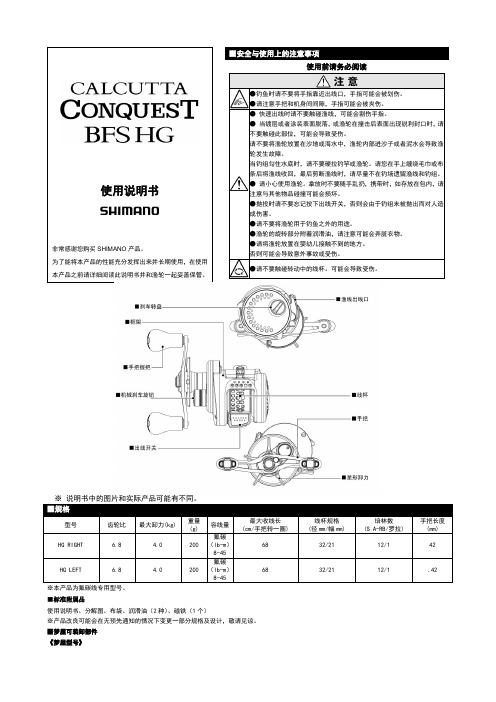
■规格型号 齿轮比 最大卸力(kg)重量 (g)容线量最大收线长 (cm/手把转一圈)线杯规格 (径mm/幅mm)培林数 (S A-RB/罗拉)手把长度 (mm) HG RIGHT6.84.0200 氟碳(lb-m )8-45 6832/2112/142HG LEFT 6.8 4.0200 氟碳(lb-m )8-4568 32/21 12/1 .42※本产品为氟碳线专用型号。
■标准附属品使用说明书、分解图、布袋、润滑油(2种)、磁铁(1个)※产品改良可能会在无预先通知的情况下变更一部分规格及设计,敬请见谅。
■梦屋可装卸部件 《梦屋型号》※详细请确认SHIMANO官网信息。
使用方法•渔轮的准备※说明书中的图片和实际产品可能有所不同。
SHIMANO 电动轮 产品使用说明书

产品使用说明书感谢您购买SHIMANO电动轮在使用本产品之前详细阅读此说明书并与渔轮一起妥善保管。
28■MENU/R/S[编辑/乐速]按钮按下EDI T 可进行编辑自动铁板模式的设定方法手动铁板模式的收线速度设定方法▲▼按钮根据自身喜好设定收线速度,然后再按下EDI T 按钮▲◎菜单界面通过移动光标,可以依次选择菜单中的各项功能。
每项功能的当前设定在该功能名称右边显示。
(图示仅作参考)在功能设定完成后,会返回菜单界面。
需要返回水深显示画面时,在菜单选中「水深画面」按确认按钮。
(确认按钮指按键区域中标有菜单的按钮,对应屏幕中的决定功能)※把默认设定更改后,即使重新启动电动轮也使用最新设定。
在菜单界面下通过光标选中功能按下[确认]后,该功能的设定画面将会显示。
功能中可变更的设定项如右图所示。
将设定调整为打开之后,收线速度设定画面将会如右上图显示通过[▼][]按钮来调整收线速度,按下[决定]设定收线速度的方式▲现在定设如果设置为打开的话需要调整具体收线速度(默认设定数值: 15)①②③④⑤设设钓组在水面时的位置记录为0M电动收线结束后,设定成将鱼竿立起就能把钓组拿到手中。
※初次使用船沿自动停止功能时,会在6m的位置启动。
第二次开始后,系统会自动记忆上次鱼竿停止5秒以上的位置。
(这个功能会在1m-6m的范围内启动,水深显示不满1m时,会被系统判定为1m)。
※浮游钓模式下,防止收线过度的程序会启动,自动设定的船沿停止功能不会启动,将会在离手比较远的地方停止收线。
电动收线结束后,将鱼竿立起就能把钓组拿到手中。
(现在设定)渔线实际位置和标44可以选择上部开始或底部开始的方式来锁定钓层。
能否准确到达鱼群所在钓层可谓是决定船钓收获好坏的重要因素。
凭借鱼探,可以准确掌握鱼群所在深度。
通常船长也会告知这一讯息。
根据钓场、钓技和目标鱼种等因素的不同,这一水深可能是从水面往下的距离也可能是从底部往上的距离。
本产品具有对应的两种水深显示方式,可供钓友根据不同情况选择。
禧玛诺SHIMANO套件名称及特性--各等级配件说明

禧玛诺SHIMANO套件名称及特性--各等级配件说明禧玛诺SHIMANO套件名称及特性运动级别的山地越野用套件,从高到低的名称依次是:XTR、Deore XT、Deore LX、Deore、ALIVIO、Acera、ALTUS、TOURNEY,更低的C050,SIS之类民用变速不在此列,另外还有HONE(介于XT和LX之间,适用重型XC和AM)、SAINT(介于XTR 和XT之间,适用于AM和FR)、适用于小轮车的DXR,capreo用的较少。
运动级别公路用套件,从高到低的名称依次是:DURA-ACE、Ultegra、105、TIAGRA、SORA、2200,更低的用于民用的A050和SIS都不在此列。
SHIMANO套件档次定位山地越野:XTR是竞赛级、Deore XT是高级训练级、Deore LX是专业训练级、Deore是专业入门级、ALIVIO是高级娱乐级、Acera和ALTUS都是娱乐级、TOURNEY算是入门娱乐级。
Deore是个分水岭,Deore(含)以上都可以称为专业级。
公路:DURA-ACE是竞赛级、Ultegra称为专业训练级、105是专业入门级、TIAGRA是业余级别、SORA是娱乐级、2200算是入门娱乐级。
这其中105是个分水岭,105(含)以上都可称之为专业级。
以上的级别分法是比较含糊的,所谓娱乐就是特指非代步的骑行运动,下面再来精细分级。
SHIMANO套件区别截至现在(2008年)SHIMANO各等级套件的型号为(从低到高细述): 山地越野:TOURNEY、ALTUS;Acera(M340)、ALIVIO(M410)、Deore(M530 碟刹为M535)、Deore LX(M580 碟刹为M585)、Deore XT(M775 碟刹为M765)、XTR(M975 碟刹为M975)、另外还有HONE(M601)、SAINT(M800) 公路用套件:2200、SORA(3300)、TIAGRA(4500)、105(5600)、Ultegra(6600)、DURA-ACE(7800)山地越野:TOURNEY严格来说不算完整的一套套件,它的定位是入门运动支持6/7速 Acera和ALTUS没有显著的区别,价格也相差很小,可以简单的理解为同一层次,Acera主要配置8速,而Acera和ALTUS主要配置7速(其实他们都可以同时兼容7速和8速),相对TOURNEY来说,增加了8速的支持, Acera的后拨连接销其中有一个轴套上有氟涂层,阻力更小更耐磨些。
山地车前拨,后拨简单调试方法(图文并茂)
发现近期很多骑车的朋友提出关于前拨后拨调试的问题,我准备给大家简单的讲解一下。
前拨后拨是属于变速套件的核心部分,他们出现问题轻则发出噪音,磨损部件,重则零件崩溃,发生车毁人亡的事故,素以一定要注意维护和保养,遇到自己不能调节的问题时,要尽快去车店解决。
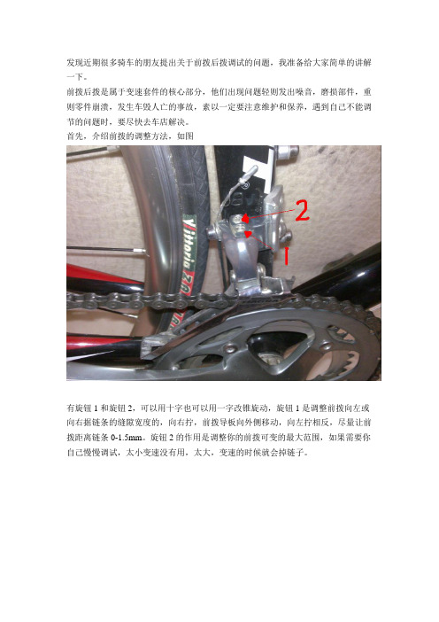
首先,介绍前拨的调整方法,如图
有旋钮1和旋钮2,可以用十字也可以用一字改锥旋动,旋钮1是调整前拨向左或向右据链条的缝隙宽度的,向右拧,前拨导板向外侧移动,向左拧相反,尽量让前拨距离链条0-1.5mm。
旋钮2的作用是调整你的前拨可变的最大范围,如果需要你自己慢慢调试,太小变速没有用,太大,变速的时候就会掉链子。
接下来,是后拨的调整方法,你可以选择像这样将车反过来
这样可以让你更好的调整后拨,后拨的方法和前拨基本类似。
如图
旋钮1是调整变速的左右,可以调整后拨的左右,向右拧,后拨向右偏,向左拧相
反,上面的旋钮2是调整变速范围,也同前拨一样,切忌不要宁得太紧,更不要拧得太松,否则后者掉链子,或者后拨蹭后轮辐条。
(整理)SHIMANO禧玛诺前后变速器校调含链条设定.

SHIMANO前後變速器校調含鏈條設定<一>前變速器1.前變速器的安裝位置前變速器之導鏈片外側於距離大齒盤垂直正上方時,建議距離約1~3m2.低位螺絲調整內導鏈片與鏈條距離為0~0.5mm。
螺絲轉動1/8圈(45度)=導鏈片移動 0.4mm3.高位螺絲調整調整高位螺絲,外導鏈片與鏈條距離為0~0.5mm4.微調螺絲微調螺絲順時針旋轉時,導輪向內側移動。
反之,逆時針旋轉時,導輪向外側移動5.簡易調整指南:◎鏈條脫落到曲柄端順時鐘旋緊高位螺絲(約1/4圈)◎中片齒盤變速到大片齒盤困難逆時鐘放鬆高位螺絲(約1/8圈)◎中片齒盤變速到小片齒盤困難逆時鐘放鬆低位螺絲(約1/4圈)◎若鏈條檔位處於大齒片時,和前變內導板發生摩擦順時鐘旋緊高位螺絲(約 1/8圈)◎若鏈條檔位處於大齒片時,和前變外導板發生摩擦逆時鐘放鬆高位螺絲(約 1/8圈)◎大齒片退檔到中齒片,鏈條會跳來跳去逆時針放鬆微調螺絲(outer casing adjustment barrel)1~2圈◎變速設定大齒盤於中片、飛輪於最大片時,鏈條和前變內側導板發生摩擦順時針旋緊微調螺絲1~2圈◎鏈條脫落到五通端順時鐘旋緊低位螺絲(約1/2圈)◎自中片齒片變速到大片手感吃力逆時鐘放鬆高位螺絲(約1/4圈)<二>後變速器1.高位螺絲調整變速至最重檔位,調整高位螺絲(H),讓Guide pulley對齊最小片飛輪外側2.低位螺絲調整變速至最重檔位,調整低位螺絲(L),讓Guide pulley對齊最大片飛輪中心3.B-tension鏈條位於大齒盤小片與飛輪最大片時,轉動曲柄。
調整B-tension螺絲讓guide pulley盡可能靠近飛輪(約5~6mm),但勿相互接觸。
接著,將鍊條變速至最小片飛輪,重覆上述動作。
順時針旋緊為加大距離,逆時針旋鬆為縮短距離4.變速微調1由後方向前看,微調螺絲順時針旋緊時,導輪向外側移動2微調螺絲逆時針旋緊時,導輪向內側移動3後變速器安裝置車架後勾爪,須注意車架確實抵住後變速器卡榫4變速線安裝必須與溝槽吻合5後變速包容量(Total Capacity)公式:(齒盤大片-小片)+(飛輪大片-小片)例:(53-39)+(34-11)=37<三>夾器登山車夾器<四>鏈條1.鏈條長度設定齒數比較大之飛輪:如11-34、11-32、11-28等,一般為登山車鏈條位於最大片齒盤與飛輪狀態下加二目鏈條,即為標準長度齒數比較小之飛輪:如11-23、11-25、12-27等,一般為公路車。
运动自行车变速器的调节(SHIMANO)前变
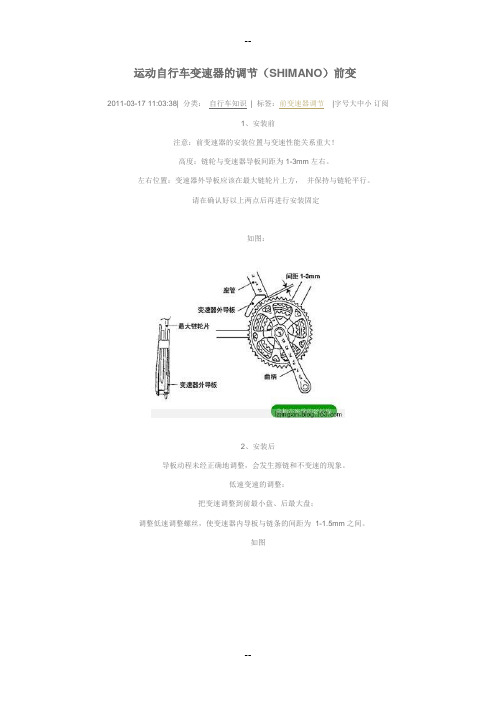
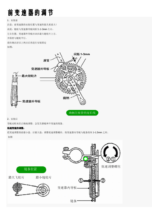
运动自行车变速器的调节(SHIMANO)前变2011-03-17 11:03:38| 分类:自行车知识| 标签:前变速器调节|字号大中小订阅1、安装前注意:前变速器的安装位置与变速性能关系重大!高度:链轮与变速器导板间距为1-3mm左右。
左右位置:变速器外导板应该在最大链轮片上方,并保持与链轮平行。
请在确认好以上两点后再进行安装固定如图:2、安装后导板动程未经正确地调整,会发生擦链和不变速的现象。
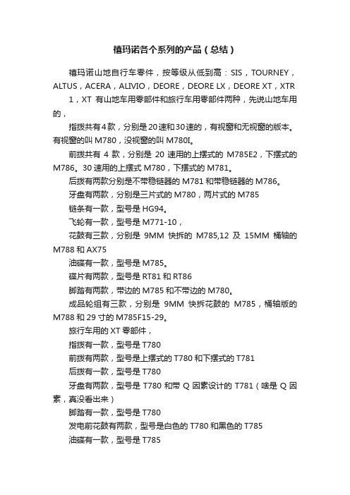
低速变速的调整:把变速调整到前最小盘、后最大盘;调整低速调整螺丝,使变速器内导板与链条的间距为 1-1.5mm之间。
如图高速变速的调整:把链条调整为后最小盘、前最大盘调整高速调整螺丝,使变速器外导板与链条的间距为 1-1.5mm之间。
如图:一、SHIMANO前变速器的类型A. 上摆式上拉B. 上摆式下拉C. 下摆式上拉D. 下摆式下拉E. E Type注1:上拉或下拉是指变速线走线的方向,是往上(经立管往上管至变速拨杆)还是往下(经BB至下管至变速拨杆),有許多变速器是上下拉共用的。
注2:所谓摆是指金属的导板,而上摆或下摆是指与固定在立管上的固定环的相对位置,导板比固定环高的称之为上摆式,而比固定环低的导板称之为下摆式二、前变变速器调整A.前置动作1. 將变速器降到最松的档位(大盘中的最小盘)。
2. 將变速器上的H/L调整螺丝放松。
B.前变速器高度调整1. 將变速器往外推(此时因沒有拉线,变速器应该是降到最小齿的位置)让导板外测与大盘在一直线上。
2. 导板外侧的內缘距离大盘的最大齿約1~3mm为正确的高度位置,确定后先將前前速器略为固定。
注1:此处指的导板外缘是指外缘中往內凹的部份为准。
注2:全新变速器导板上有一张贴纸(上面有齿狀线条),通常是有附调整棒,不要將其取下,以方便调整。
注3:若是前变速器水平位置太高,会导致变速时链条会打到导板下线注4:若是前变速器水平位置太低,会导致变速时导板会打到大齿盘C.前变速器导板水平调整1. 将前变速器导板内侧调整至与大盘平行。
SHIMANO产品说明书

使用说明书非常感谢您购买SHIMANO产品。
为了能将本产品的性能充分发挥出来并长期使用,在使用本产品之前请详细阅读此说明书并和渔轮一起妥善保管。
各部位的名称和特征规格型号齿轮比最大卸力(kg)重量(g)PE线容量(号-m) 最大收线长(cm/手把转一圈) 手把长度(mm) 培林数(BB/罗拉)1000HG 6.4 7.0 430 2-300、2.5-230、3-200 98 73/85 8/1 1001HG 6.4 7.0 430 2-300、2.5-230、3-200 98 73/85 8/1 1500HG 6.4 7.0 430 2-500、2.5-400、3-320 98 73/85 8/1 1501HG 6.4 7.0 430 2-500、2.5-400、3-320 98 73/85 8/1 2000NRHG 6.2 10.0 605 3-400、4-300、5-220 117 80/92 8/1 2001NRHG 6.2 10.0 605 3-400、4-300、5-220 117 80/92 8/1 3000HG 6.2 10.0 630 3-670、4-480、5-400、6-330 117 80/92 8/1 ●线杯卷线部位的沟槽,分别指示1/3、2/3的位置。
●容线量是按照1.0kg的渔线张力缠绕在OCEA EX8上的数值。
●产品改良可能会在无预先通知的情况下变更一部分规格及设计,敬请见谅。
●容线量是以包握侧的线杯边缘为基准的。
■线杯卷线时的注意事项在卷PE 线时,请务必固定线杯并防止打滑后在开始卷线。
如果直接卷线可能造成空转,并且线越不易卷好。
此外,本产品为PE线专用的轻量线杯,当用过高的渔线张力绕卷时,可能会导致线杯变形,敬请注意。
禧玛诺推荐的线张力是1kg。
另外,备线使用尼龙线时,请使用6号以上的粗线,注意不要过度拉紧线。
(备线尼龙线的推荐张力:500g)■手把装卸时的注意事项※拆装手把时,请使用螺母尺寸11mm,外径16.5mm以内的六角套筒扳手。
SHIMANO配件调节及安装的说明书
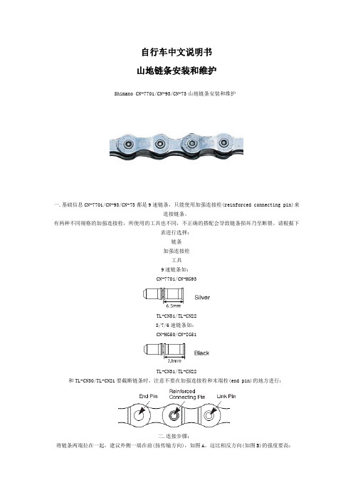
自行车中文说明书山地链条安装和维护Shimano CN-7701/CN-93/CN-73山地链条安装和维护一.基础信息CN-7701/CN-93/CN-73都是9速链条,只能使用加强连接栓(reinforced connecting pin)来连接链条。
有两种不同规格的加强连接栓,所使用的工具也不同,不正确的搭配会导致链条损坏乃至断裂。
请根据下表进行选择:链条加强连接栓工具9速链条如:CN-7701/CN-HG93TL-CN31/TL-CN228/7/6速链条如:CN-HG50/CN-IG51TL-CN31/TL-CN22和TL-CN30/TL-CN21要截断链条时,注意不要在加强连接栓和末端栓(end pin)的地方进行:二.连接步骤:将链条两端拉在一起,建议外侧一端在前(按传输方向),如图A。
这比相反方向(如图B)的强度要高:插入加强连接栓:用工具将连接栓按进链条内:到位后的样子:用工具拔掉多余的部分:注意:固定栓在链条两侧的突出程度要一样。
三.维护链条上油前先清洗干净。
不要使用酸性材料做清洗剂。
洗完后用清水除去清洗剂。
当链条完全干燥后再上油。
定期的润滑能延长链条的使用寿命。
润滑油要上在链条的关节处,并让其渗进去。
行车中文说明书——Shimano CS-M970/CS-M760/CS-M580山地飞轮安装和维护Shimano CS-M970/CS-M760/CS-M580山地飞轮安装和维护一.规格表XTRDEORE XTDeore LX型号CS-M970CS-M760CS-M580类型HG Cassette Sprocket速级9链条Super Narrow HG for 9-speed齿数(ba)11-32T(be)11-34T(bd)12-34T(aq)11-32T(as)11-34T(ar)11-32T(au)11-34TSprocket MaterialSteel-5/Ti-4steelsteelSprocket FinishNickel/Titaniumchrome platedpearl bright finish齿数:11-32T:11-12-14-16-18-21-24-28-3211-34T:11-13-15-17-20-23-26-30-3412-34T:12-14-16-18-20-23-26-30-34二.安装(1).对齐安装位置每个飞轮齿片有标记的那面要装在外侧。
SHIMANO前后变速器校调含链条设定共6页word资料
SHIMANO前后变速器校调含链条设定■前变速器1.前变速器的安装位置前变速器之导链片外侧于距离大齿盘垂直正上方时,建议距离约1~3m2.低位螺丝调整内导链片与链条距离为0~0.5mm。
螺丝转动1/8圈(45度)=导链片移动0.4mm3.高位螺丝调整调整高位螺丝,外导链片与链条距离为0~0.5mm4.微调螺丝微调螺丝顺时针旋转时,导轮向内侧移动。
反之,逆时针旋转时,导轮向外侧移动5.简易调整指南:◎链条脱落到曲柄端顺时钟旋紧高位螺丝(约1/4圈)◎中片齿盘变速到大片齿盘困难逆时钟放松高位螺丝(约1/8圈)◎中片齿盘变速到小片齿盘困难逆时钟放松低位螺丝(约1/4圈)◎若链条档位处于大齿片时,和前变内导板发生摩擦顺时钟旋紧高位螺丝(约1/8圈)◎若链条档位处于大齿片时,和前变外导板发生摩擦逆时钟放松高位螺丝(约1/8圈)◎大齿片退档到中齿片,链条会跳来跳去逆时针放松微调螺丝(outer casing adjustment barrel)1~2圈◎变速设定大齿盘于中片、飞轮于最大片时,链条和前变内侧导板发生摩擦顺时针旋紧微调螺丝1~2圈◎链条脱落到五通端顺时钟旋紧低位螺丝(约1/2圈)◎自中片齿片变速到大片手感吃力逆时钟放松高位螺丝(约1/4圈)■后变速器1.高位螺丝调整变速至最重档位,调整高位螺丝(H),让Guide pulley对齐最小片飞轮外侧2.低位螺丝调整变速至最轻档位,调整低位螺丝(L),让Guide pulley对齐最大片飞轮中心3.B-tension链条位于大齿盘小片与飞轮最大片时,转动曲柄。
调整B-tension 螺丝让guide pulley尽可能靠近飞轮(约5~6mm),但勿相互接触。
接着,将链条变速至最小片飞轮,重复上述动作。
顺时针旋紧为加大距离,逆时针旋松为缩短距离4.变速微调1、由后方向前看,微调螺丝顺时针旋紧时,导轮向外侧移动2、微调螺丝逆时针旋紧时,导轮向内侧移动3、后变速器安装置车架后勾爪,须注意车架确实抵住后变速器卡榫4、变速线安装必须与沟槽吻合5后变速包容量(Total Capacity)公式:(齿盘大片-小片)+(飞轮大片-小片)例:(53-39)+(34-11)=37■链条1.链条长度设定▲齿数比较大之飞轮:如11-34、11-32、11-28等,一般为登山车链条位于最大片齿盘与飞轮状态下加二目链条,即为标准长度;齿数比较小之飞轮:如11-23、11-25、12-27等,一般为公路车。
前拨调节指南
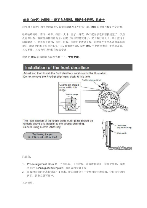
前变速(前拨)和手变的调整安装指南翻译及小小经验(以4503前拨和4500手变为例)哈哈哈哈哈哈,奋斗一中午,挥汗一大斗,湿了一身衣,终于把左手边和前拨搞定了,虽然没有像后拨、右前变那样轻松写意,但是已经很容易变速了,费了有好几天了,终于把这个问题解决了。
我也写个教程,总结下经验,也给后来者提个醒,前拨和左手变不是像车行所说的,就是硬的和茅坑里的石头一样,搬都搬不动,或者4500手变级别太差,手感就是硬。
其实不然,其实也可以轻松自如的变速。
我就把4503前拨的官方说明先翻一下,首先安装,注意点:1, Pro-setalignment block是一个塑料块,卡住前拨,让前拨伸展开,这样安装时,前拨外导栏(chain guideouter plate)就可以和大盘平行2,前拨和大盘的距离控制在1-3毫米,新的前拨会有一个塑料指示薄膜的,会指出合适的间距,调整完就可撕掉。
其次调整:Step 1:调整小档要求:大飞,小盘,去掉预设塑料块(Pro-setalignment block),这样前拨就缩回去了,操作:调整L限位螺丝,使得前拨内导栏与链条平行,距离0-3毫米。
注意:HL限位前拨各有不同,4503下拉式的前拨,里面这个(上图左边)这个是L限位,旋紧(A方向,顺时针)是让前拨右导栏往小盘靠拢,-- 其实不管是HL限位,旋紧(顺时针方向)都是让前拨导栏向牙盘靠拢STEP 2:拉上线要求:将变速线和前拨连上,卡紧注意点:1,卡线不能卡的太死,不然会把线压散,有扭力扳手就好了,我是靠感觉,变速线呢已经被我压扁压散了,唉。
2,卡线的地方有个小槽(突起),把线卡在里面;3,变速线觉得难拉紧的,可以用outer casing adjustment barrel (这个学名叫什么?后面会提到)让变速线先松松,再旋一下,把线拉紧就好了SETP 3:调大档要求:小飞,大盘,操作:调整H限位螺丝,使得前拨外导栏与链条平行,距离0-3毫米。
禧玛诺前、后拨安装及调整

6)中间齿片变速调整(变速线张力)
变速线张力调整螺钉
L 2 3 4 5 H
中间所有位置移动的调整
7)B张力调整螺钉调整 一般情况下,是不需要调整B张力螺钉。 该螺钉的作用,是使得导轮靠近齿片,直至链条不打结拥塞。 使得后拨导轮和飞轮之间的间隙在8-11mm(限RDTZ系列后拨) 调整该螺钉时,链条是处于前面最小片,后面最大片的状态。
内线锁在锁线槽上
4)低位调整 一边旋转前链轮一边操作变速手柄,使之变速至最大齿片,旋 转低位调整螺钉(L) 使引导轮中心线处于最大齿片的正下方
5)变速器高低位调节螺钉图例(高·低位)
L 2 3 4 5 H 定位调整螺钉 飞轮片
后拨导轮 定位螺钉仅调整 高位(H)和低位(L)位置, 不可以调整中间变速
注意事项
导致变速不顺畅或链条掉链的现象原因:
1、钢线张力太紧或太松 2、钢线锁紧路径错误 3、内线摩擦力太大 4、后下叉勾爪变形 5、高、低位限位螺钉调整不到位
二、前拨链器的安装与பைடு நூலகம்整
1.调整前拨链器高度
使导板与最大齿轮片高度保持1~3mm(此时不要拆卸预置对准块)
2.调整前拨链器角度 ①使得链条导板的外侧平 坦部分处于大齿片的垂直 上方,且于大齿片平行。 ②使用5毫米内六角扳手将 其拧紧。 锁紧力矩: 5~7N·m(50 ~70kgf·cm)
内,外导板
前、后拨的安装和调整
一、后拨链器的安装和调整
二、前拨链器的安装和调整
1.后拨链器安装
安装时,请注意勿使B张力调整螺钉接触至"后下叉端片"而引起变形 锁紧力矩:8~10N·m(80 ~100kgf·cm)
2.SIS调整
1)高位的调整 从后方看过来,旋转高位调整螺钉( H ),使导轮中心在最小齿片 外侧延长线上,然后安装好链条
SHIMANO禧玛诺变速器的调节
前变速器的调节1、安装前注意:前变速器的安装位置与变速性能关系重大!高度:链轮与变速器导板间距为1-3mm左右。
左右位置:变速器外导板应该在最大链轮片上方,并保持与链轮平行。
请在确认好以上两点后再进行安装固定如图:2、安装后导板动程未经正确地调整,会发生擦链和不变速的现象。
低速变速的调整:把变速调整到前最小盘、后最大盘;调整低速调整螺丝,使变速器内导板与链条的间1-1.5mm之间。
如图高速变速的调整:把链条调整为后最小盘、前最大盘调整高速调整螺丝,使变速器外导板与链条的间距为 1-1.5mm之间。
如图:后拨调校技巧1.将前链条置於大齿盘上,後链条则拨入小齿轮。
如下即可确定外部作业位置:先将上方小导轮精确地置於最小的小齿轮位置─如为Shimano系统为上方的小螺丝,ESP系统为下方螺丝,而Di.R.T的变速系统则为前方的调校螺丝。
此项工作也可在链条及变速缆线组装之前进行。
(转注:对于喜马诺就是说大盘小飞定外侧)2.变速缆线最慢在此时即须卡上(之前应是将变速器及变速杆上的调螺丝转紧一圈)。
而後以变速器调节螺丝将缆线轻调至紧绷的程度。
如为Sram的组件─不论是Di.R.T.或ESP系列─则可减省此手续。
只须将缆线以右旋把上的调节螺丝调紧即可。
(转注:把指拨从最小的档位象前拨一档(由于才装了线,线一定是松的后拨一定不能变到上面一档。
)在用手转动后拨的微调螺丝。
边调边让后飞转动。
你会发现你转一下后拨就会象上走一点。
一直转到链条上到上面一个齿轮上。
在转动一点。
)3.至於内部作业机制方面,须将後方的链条拨入最大的小齿轮上,前方则置於小齿盘上。
此时即可转动─依变速器型式不同而有异─其他各颗调节螺丝至最紧,使上方的小导轮精确地在大齿轮下方进行变速动作,注意须达其极致点。
如不然,在历经一段美好的自行车之旅後,即可能因链条小齿轮与轮辐之间的拉动而造成轮辐断裂。
(转注:对于喜马诺就是说小盘大飞定内侧)4.现在应利用所谓的B号起子,将後变速器调整至最大的小齿轮与上方小导轮之间,直到空出一个半链环的空间为止。
shimano禧玛诺鱼竿安全使用说明书
安全注意事项接节部难以拔出的时候使用带导环并继/印笼继竿时使用印笼继/逆印笼继竿时禧玛诺(上海)贸易有限公司中国上海市长宁区凯旋路1388弄1幢201-203室邮编:200052官方网站: 官方微信号:禧玛诺渔具官方微信二维码:鱼竿使用注意事项使用时需注意鱼竿竿身上有触电注意标贴,标贴为了不轻易被剥离施加了涂层,请不要用手去剥,另外,有部分商品的触电注意标贴是印刷上去的。
当产品故障时请联系您购买的店铺或就近的SHIMANO专柜店,如果您不清楚专柜店信息,请致电SHIMANO或通过浏览官方网站了解。
同时,请提供购买时间以及确切的商品名称和商品代码。
使用无导环竿时使用带导环振出竿时使用无导环竿时使用并继/印笼继竿时接节部有沙子进去时使用带导环振出竿时请注意竿梢节、第二节、第三节接节口的折断●如不合理地去拧或撬,都可能造成竿梢折断。
●请确保活动导环固定到位,另外会造成竿梢折断。
使用鱼竿支架/鱼竿固定架时使用实心竿梢鱼竿时使用含渔轮座竿时其他注意事项●鱼竿弯曲时,由于绕线部涂厚漆的部分无法适应鱼竿的弯曲,有时会产生裂纹,但导环和鱼轮座的固定力是完全没有问题的。
目前的生产技术还无法防止这种裂纹,敬请理解。
●●请勿在渔线缠绕的状态下收主线,在鱼竿部分如果施加不合理的力量可能会造成鱼竿折断。
●在取下前堵的时候,请朝着正上方拉拔前堵,如不合理地去拧或撬,都可能造成接节扣部分损坏。
●请勿在渔线缠绕的状态下继续使用。
另外,在使用过程中请不要强行朝垂直方向拉拔,鱼竿可能会因不合理的施加力而造成损坏。
●需要收起鱼竿时请从手把节开始,在收回竿梢节、第二节、第三节等细节时,请把手把节夹在腋下并拿着接节部的上下两端,边拧边塞进去。
●当竿尾贴靠在物体进行收竿时,请贴靠在质地柔软的东西上,从手握竿的地方依次一根一根收纳。
这时请注意不要让竿尾碰到水。
●用腋下夹住鱼竿收竿或出竿时,长竿会相对更易以施加力量,请注意不要太用力避免损伤第二节、第三节的玉口。
手把手教你如何调整喜马诺变速器

⼿把⼿教你如何调整喜马诺变速器前后拨调试的简单理解及前拨的安装前拨调整(以SHIMANO DEORE LX为例):按以下简单规律进⾏反复调试。
H螺丝——⽤来调整链条在最⼤盘⽚时的定位。
逆时针(旋出):前拨臂远离坐管;顺时针(旋进):前拨臂靠近坐管。
注意:逆时针(旋出)要掌握好尺度,太过,会导致链条脱盘,卡在曲柄与⼤盘之间,很危险。
L螺丝——⽤来调整链条在最⼩盘⽚时的定位。
逆时针(旋出):前拨臂靠近坐管;顺时针(旋进):前拨臂远离坐管。
注意:逆时针(旋出)要掌握好尺度。
太过,会导致链条脱盘,卡在五通与⼩盘之间,很危险。
后拨调整(以SHIMANO DEORE LX为例):按以下简单规律进⾏反复调试。
螺丝1——⽤来调整链条在最⼩飞时的定位。
逆时针(旋出):后拨臂远离轮组;顺时针(旋进):后拨臂靠近轮组。
注意:逆时针(旋出)或顺时针(旋进)要掌握好尺度,确保最⼩飞与后拨导轮在同⼀平⾯。
螺丝附近可以发现附件有h的字样,这代表high,也就是我们常说的⾼速档限位螺丝,这个螺丝的作⽤是调整后拨向最⼩齿⽅向收缩的距离,这个螺丝太紧会造成链条7速,8速,9速的系统,档位显⽰到7,8,9时,链条不能到位,⽽在最⼩飞⽚和第⼆⼩飞⽚间跳动,如果将这个螺丝逆时针调整到太松,那⼜可能产⽣下到最⼩齿以外的地⽅(脱链),所以这个螺丝是专门控制链条在最⼩齿的左右最终位置的。
螺丝2——⽤来调整链条在最⼤飞时的定位。
逆时针(旋出):后拨臂靠近轮组;顺时针(旋进):后拨臂远离轮组。
注意:逆时针(旋出)时,要掌握好尺度,太过,会导致链条脱飞,夹在辐条与飞轮之间,很危险。
螺丝附近有L字样,那个螺丝是代表low,是我们所说的低速限位螺丝,那个螺丝控制这链条上最⼤飞的位置,调整到位时,链条可以轻松进⼊⼤飞⽚,并且不会向内侧脱链在飞于辐条之间的空间中,也不会让后拨直接接触辐条,那个螺丝过松会造成上⾯的这两种情况,⽽过紧会产⽣⽆法拨上最⼤飞⽚,或者控制飞轮的变速器在1档时,链条在最⼤和第⼆⼤飞⽚之间跳动。
禧玛诺各个系列的产品(总结)
禧玛诺各个系列的产品(总结)禧玛诺山地自行车零件,按等级从低到高:SIS,TOURNEY,ALTUS,ACERA,ALIVIO,DEORE,DEORE LX,DEORE XT,XTR 1,XT有山地车用零部件和旅行车用零部件两种,先说山地车用的,指拨共有4款,分别是20速和30速的,有视窗和无视窗的版本。
有视窗的叫M780,没视窗的叫M780I。
前拨共有4款,分别是20速用的上摆式的M785E2,下摆式的M786。
30速用的上摆式M780,下摆式的M781。
后拨有两款分别是不带稳链器的M781和带稳链器的M786。
牙盘有两款,分别是三片式的M780,两片式的M785链条有一款,型号是HG94。
飞轮有一款,型号是M771-10,花鼓有三款,分别是9MM快拆的M785,12及15MM桶轴的M788和AX75油碟有一款,型号是M785。
碟片有两款,型号是RT81和RT86脚踏有两款,带边的M785和不带边的M780。
成品轮组有三款,分别是9MM快拆花鼓的M785,桶轴版的M788和29寸的M785F15-29。
旅行车用的XT零部件,指拨有一款,型号是T780前拨有两款,型号是上摆式的T780和下摆式的T781后拨有一款,型号是T780牙盘有两款,型号是T780和带Q因素设计的T781(啥是Q因素,真没看出来)脚踏有一款,型号是T780发电前花鼓有两款,型号是白色的T780和黑色的T785油碟有一款,型号是T785V刹有一款,刹把和夹器的型号都是T780V刹花鼓有一款,前花鼓型号是T780,后花鼓型号是T785.链条,碟片,碟刹花鼓和飞轮与XT山地车用零部件是同一款。
2,LX这个系列现在被禧玛诺划归到了旅行车用零部件里去了指拨有一款,型号是T670前拨有两款,上摆的叫T670,下摆的叫T671后拨有一款,型号是T670牙盘有一款,型号是T671花鼓有两款,用于V刹的叫T670,用于碟刹的叫T675发电前花鼓有两款,型号是灰色的T670和黑色的T675刹车油两款,V刹的叫T670,油碟叫T675碟片有一款,型号是RT54飞轮和链条没有专属的,随便用,10速的就行。