91R1AD22D10R51中文资料
夜鹰X10 AD7200 智能WiFi 路由器 型号R9000 用户指南说明书

更多操作Nighthawk® 夜鹰 X10 AD7200 智能 WiFi 路由器型号 R9000WiFi 网络名称和密码您路由器的预设 WiFi 网络名称 (SSID) 和网络密钥(密码)是唯一的,如同序列号一样。
路由器将自动使用 WiFi 安全措施,因此,您无需进行设置。
预设的 WiFi 网络名称和密码位于路由器标签上。
我们建议使用预设 WiFi 设置,因为您可以在忘记时查看产品标签。
您可以登录路由器来更改这些设置。
如果执行此操作,请记录新的WiFi 设置,并将其存放到安全位置。
还可以将路由器标签上的 WiFi 设置记录到此处,以便参考。
如果您更改 WiFi 设置,在此处记录新设置以便参考,并将此手册存放到安全位置。
WiFi 网络名称 (SSID):网络密钥(密码):加入 WiFi 网络您可以使用 WPS 一键加密功能,或者选择路由器的 Wi-Fi 网络并输入密码。
使用 WPS 加入网络如需在已启用 WiFi 的计算机或移动设备上使用WPS按钮获得帮助,请参阅计算机或设备随附的说明手册或在线帮助。
一些较旧的设备不能使用 WPS。
¾要使用 WPS 加入网络:1. 按住路由器上的WPS按钮三至五秒。
按钮上的 WPS LED 指示灯闪烁。
2. 在两分钟内按下已启用 WiFi 的计算机或其他移动设备上的WPS按钮,或单击其界面上的WPS按钮。
计算机或移动设备连接至路由器时,WPS LED 指示灯会保持蓝色常亮状态。
3. 重复此过程以添加其他计算机或移动设备。
使用路由器的 WiFi 设置加入 WiFi 网络使用路由器的 WiFi 网络名称和密码,将已启用 WiFi 的计算机或移动设备通过 WiFi 连接到路由器的网络。
如果没有更改路由器的 WiFi 网络名称和密码,请使用路由器标签上的预设 WiFi 网络名称和密码。
¾选择您的网络,然后输入其密码:1. 在已启用 WiFi 的计算机或移动设备上,打开管理 WiFi 连接的WiFi 连接管理器。
ICP DAS LP-51xx系列产品说明书
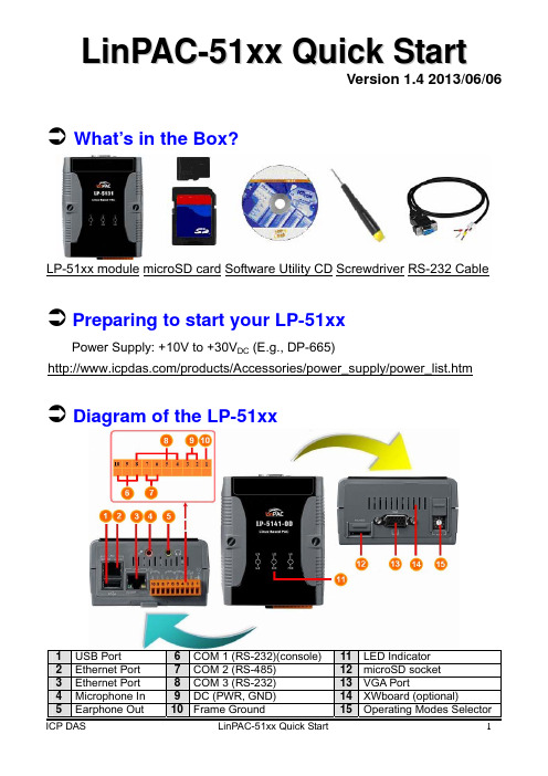
L i n P A C-51x x Q u i c k S t a r tVersion 1.4 2013/06/06 ÂWhat’s in the Box?LP-51xx module microSD card Software Utility CD Screwdriver RS-232 CableÂPreparing to start your LP-51xxPower Supply: +10V to +30V DC (E.g., DP-665)/products/Accessories/power_supply/power_list.htmÂDiagram of the LP-51xx Configuring the Operating ModeRotary Switch PositionOperation Mode0 Normal Mode(Default)1 Quick Mode2 OS Update Mode3 Debug ModeOthers ReservedNormal Mode(Default)Normal mode is the default operation mode for the LP-51xx. Use this mode to perform additional tasks and configuration. Programs are also executed in this mode. Quick ModeQuick mode is used to bypass the LP-51xx boot screen when booting form a microSD/microSDHC card, so as to speed up the booting process.OS Update ModeThis mode is used to update the OS image. Note that the Linux OS image is only suitable for the LP-51xx. If the LP-51xx cannot be booted or operated in normal mode, use this mode to update OS image again. Ensure that you backup any important files, before updating the OS image. For more information, refer to the “LP-51xx OS update manual”. Debug ModeThis mode is only for use by ICP DAS during development of the device. ReservedRotary switch positions 4~9 are reserved by ICP DAS.ÂConnecting the LP-51xx to a Windows PCThe RS-232 connector is a standard non-isolated serial port (COM1 - TxD, RxD, GND), and is located on the upper right-hand corner on theLP-51xx module.Connect the LP-51xx console to the COM port on the Host PC. Note that it is unnecessary to connect to a converter.Open HyperTerminal by clicking the Start button, point to All Programs, point to Accessories, point to Communications, and the click HyperTerminal.In the ‘Port Setting’ dialog box, set the parameters for COM 1 to 115200 bps, 8 data bits, no parity, 1 stop bit and no flow control, and thenpress the OK button to save the settings.Turn on the LP-51xx power and the following message will be displayed to indicate that the configuration process has been completed.Press ‘Enter’, you will see ‘linpac-51xx login:’ prompt.At the LP-51xx login prompt, enter the root ID and password (Default ID and password is root).ÂConnecting the LP-51xx to a Linux PCInstall a HyperTerminal tool on the Linux PC, such as Minicom, or GTKTerm, etc.Using Minicom as an example:In the terminal window, type ’minicom -s’ to enter the Minicom configuration menu. To configure the COM1 port, use the keyboardarrow keys to select the menu item labeled ‘Serial port setup’ and thenpress Enter. Set the parameters for COM 1 and then press ‘Exit’.A sample of the Minicon operation.Turn on the LP-51xx power.Once the boot sequence is complete, press ‘Enter’, you will see ‘linpac-51xx login:’ prompt.At the LP-51xx login prompt, enter the root ID and password (Default ID and password is root). Connect to the LP-51xx via TelnetIn HyperTerminal:;On a Linux PC ;On a Windows PCÂConfiguring the IP Address for the LP-51xxThere are two methods of assigning the LP-51xx network settings. The first uses DHCP and the other uses a manually Assigned IP address. The factory default setting for the LP-51xx is DHCP, and this is the easiest method. However, if your network system does not include a DHCP server, then you will need to manually configure the network settings by using the Assigned IP method. To do this:Boot the device and establish a connection to the LP-51xx via Telnet.Type in “vi /etc/network/interfaces” to open the network settings file.ÂTechnical SupportThis manual is applicable to the following devices:Module Status Module Status Module StatusoutLP-5341 PhasedLP-5141-OD OKLP-5131 OKLP-5131-OD OK LP-5331 Phased out LP-5441 Phased out LP-5141 OK LP-5431 Phased out LP-5331-XW107i OEM onlyICP DAS Website: ICP DAS Service : ******************************************。
91MCE系列限位开关说明书

DESCRIPTIONThe 91MCE Series limit switch is a compliment to Honeywell’s existing product line of smaller, lower cost limit switches. Designed for modern industrial OEMs, the miniature package size fits in applications where space is limited. The small package size can be gangmounted for applications requiring more than two switch circuits. The 20 mm mounting pattern meets most globally accepted mounting standards.This product family offers the user many options including a variety of different actuator styles. Connection options include pre-leaded cable in various lengths or M12 connectors, both with side or bottom exits. Design flexibility is further enhanced with the availability of both slow action and snap action circuitry. Direct acting contacts are designed to open the NC contact when actuated. The epoxy-sealed rugged die-cast housing provides enhanced environmental durability.Priced competitively, the 91MCE is a drop-in replacement to many products, and provides enhanced quality that customers expect from Honeywell.FEATURES•• Sealed to IP67; NEMA 1, 4, 12, 13 suitable for outdoor applications• CE, UKCA, cULus, CCC approvals meet most global approvals• Nine actuator styles offer design flexibility• Slow-action and snap-action circuitry options• Pre-leaded cable and M12 connector options• Expected mechanical life: 5 million operations• Side exit (standard) and bottom exit connection options91MCESERIESMICRO SWITCH Miniature Compact Limit Switches002311Issue 3POTENTIAL APPLICATIONS• Machine equipment • Material handling • Aerial lifts • Forklifts• Off road and outdoor equipmentPORTFOLIOThe 91MCE Series is part of the 14CE, 914CE, NGC, SZL-VL-S, SSCE and SL1 Series of miniature limit switches.Switches.PRODUCT NOMENCLATURE91MCESwitch Type16Actuator TypeCable/Connector Exit91MCE Series Miniature Compact Limit Switch1Cable Length*ConnectorNOTE: not all combinations of model codes are available.Please contact your Honeywell provider/representative for assistance.PSwitch TypeBLever TypeFOR MORE INFORMATION Honeywell Advanced Sensing Technologies services its customers through a worldwide network of sales offices and distributors. For application assistance, current specifications, pricing or the nearest Authorized Distributor, visit our website or call:USA/Canada +1 302 613 4491Latin America +1 305 805 8188 Europe +44 1344 238258 Japan +81 (0) 3-6730-7152 Singapore +65 6355 2828 Greater China +86 4006396841HoneywellAdvanced Sensing Technologies830 East Arapaho RoadRichardson, TX 75081 WARRANTY/REMEDYHoneywell warrants goods of its manufactureas being free of defective materials andfaulty workmanship during the applicablewarranty period. Honeywell’s standard productwarranty applies unless agreed to otherwise byHoneywell in writing; please refer to your orderacknowledgment or consult your local salesoffice for specific warranty details. If warrantedgoods are returned to Honeywell during theperiod of coverage, Honeywell will repair orreplace, at its option, without charge thoseitems that Honeywell, in its sole discretion,finds defective. The foregoing is buyer’s soleremedy and is in lieu of all other warranties,expressed or implied, including those ofmerchantability and fitness for a particularpurpose. In no event shall Honeywell beliable for consequential, special, or indirectdamages.While Honeywell may provide applicationassistance personally, through our literatureand the Honeywell web site, it is buyer’s soleresponsibility to determine the suitability ofthe product in the application.Specifications may change without notice.The information we supply is believed tobe accurate and reliable as of this writing.However, Honeywell assumes no responsibilityfor its use.m WARNINGMISUSE OFDOCUMENTATION• The information presented in thisproduct sheet is for reference only.Do not use this document as aproduct installation guide.• Complete installation, operation,and maintenance informationis provided in the instructionssupplied with each product.Failure to comply with theseinstructions could result in death orserious injury.002311-3-EN | 3 | 12/21。
ZV14K2220122R1中文资料(STACKPOLE)中文数据手册「EasyDatasheet - 矽搜」
ZV 17 K 1206 201 17 22 27 44 1.0 0.7 0.008 200 740 1.8
ZV 20 K 1206 201 20 26 33 54 1.0 0.8 0.008 200 620 1.8
ZV 25 K 1206 201 25 31 39 65 1.0 1.0 0.008 200 510 1.8
芯片中文手册,看全文,戳
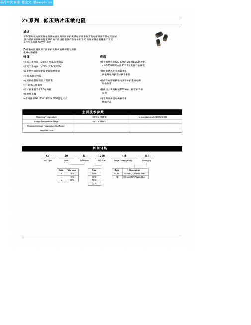
ZV系列 - 低压贴片压敏电阻
描述
该ZV系列低电压压敏电阻器被设计用来防护护敏感电子设备免受高电压浪涌在低电压区域 .他们提供出色瞬态能量吸收由于改进能量体产品分布和功耗.低压压敏电阻覆盖广直流 工作电压范围为3V至125V.
ZV压敏电阻通常用于防护护在集成电路和其它部件
40 56 68 110 3.0
2.4 0.010 250
750 1.8
50 65 82 135 3.0
1.7 0.010 250
650 1.8
60 85 100 165 3.0
2.2 0.010 250
500 1.8
95 125 150 250 3.0
2.6 0.010 200
300 1.8
L
(毫米)
ZV 35 K 1812 601 35 45 56 90 5.0
ZV为40K 1812 601 40 56 68 110 5.0
ZV 50 K 1812 401 50 65 82 135 5.0
ZV 60 K 1812 401 60 85 100 165 5.0
ZV 95 K 1812 301 95 125 150 250 5.0
3.20 ± 0.30 1.60 ± 0.20 1.6
3.20 ± 0.30 1.60 ± 0.20 1.6
MB1联网播放器规格书说明书

联网播放器系列MB1规格书目录深圳市摩西尔电子有限公司FPGA接收卡系列C12规格书目录1产品概述 (1)产品简介 (1)产品特色 (1)2功能介绍 (2)3产品参数 (4)基本参数 (4)硬件介绍 (4)输出接口定义 (5)指示灯说明 (9)尺寸图 (9)4产品规格 (10)规格参数 (10)注意事项 (10)更新记录文档版本发布时间更新记录V3.02020年8月1日第一次发布V3.12020年12月7日修改功能描述产品简介C12是摩西尔自主研发推出的一款小尺寸大的高端接收卡,带载8192像素点;具有强大的处理能力、超稳定性能及超高性价比快速取得用户青睐。
C12的尺寸仅为(70mm x24 mm),这是业内能够实现的最小的外形尺寸,能够节省设计空间、减少屏体外部线缆、简化屏体结构设计、降低设计难度,可以帮助客户实现前所未有的创新设计;解决了屏体空间受限、屏体防护难题、售后服务难题、和价格难题,将进一步为差异化产品设计提供竞争优势。
产品特色采用小的尺寸和厚度,为日趋狭窄的箱体空间和灯条空间节省空间;板卡输出采用通用2.0mm间距接插件接口,具有高稳定性和高可靠性;采用新一代图像处理内核,在显示效果方面获得极大提升;单卡输出串行RGB数据24组,并行8组,支持4个时钟扩展;支持8192点以内,任意设置;超小尺寸设计(70mm x24mm),解决空间设计难题;强大的LED驱动芯片兼容能力,支持所有芯片的驱动;支持安全升级;支持亮度校正,色度校正支持单卡位置任意偏移,单卡显示内容旋转,实现异形屏幕;减少线缆和连接器的数量,简化LED显示屏结构设计。
信号传输只需要2芯超五类双绞线,可让显示屏信号和电源的布线合二为一设计,外设级联连接线由传统的二进二出变为一进一出;显示屏的灯板可与接收卡集成模块化设计,出现故障时只需对模块进行单独拆卸更换,让售后维修变得简单,降低后期的维护成本;采用全封闭设计,简化设计,提高电磁兼容性,有助于用户产品顺利通过EMC认证;应用场景可广泛应用于灯条屏,贴膜屏、玻璃屏、网格屏,灯饰屏等空间要求严格的应用场景。
国产ds1991L-F5 参数说明书

SELOCKEY.SOA§ 1,152-bit secure read/write, nonvolatilememory§ Secure memory cannot be decipheredwithout matching 64-bit password§ Memory is partitioned into 3 blocks of 384bits each§ 64-bit password and ID fields for eachmemory block§ 512-bit scratchpad ensures data transferintegrity§ Operating temperature range: -40°C to+70°C§ Over 10 years of data retentionCOMMON Button FEATURES§ Unique, factory-lasered and tested 64-bitregistration number (8-bit family code + 48-bit serial number + 8-bit CRC tester) assures absolute traceability because no two parts are alike§ Multidrop controller for MicroBUS§ Digital identification and information bymomentary contact§ Chip-based data carrier compactly storesinformation§ Data can be accessed while affixed to object § Economically communicates to bus masterwith a single digital signal at 16.3k bits per second§ Standard 16 mm diameter and 1-Busprotocol ensure compatibility with Button family§ Button shape is self-aligning with cup-shaped probes§ Durable stainless steel case engraved withregistration number withstands harsh environments§ Easily affixed with self-stick adhesivebacking, latched by its flange, or locked with a ring pressed onto its rim§ Presence detector acknowledges when readerfirst applies voltageF5 MICROCAN TMAll dimensions shown in millimetersORDERING INFORMATIONTM1991L-F5F5 MicroCanTM1991MultiKey Button TMTM1991 Button DESCRIPTIONThe TM1991 MultiKey Button is a rugged read/write data carrier that acts as three separate electronic keys, offering 1,152 bits of secure, nonvolatile memory. Each key is 384 bits long with distinct 64-bit password and public ID fields (Figure 1). The password field must be matched in order to access the secure memory. Data is transferred serially via the 1-Bus protocol, which requires only a single data lead and a ground return. The 512-bit scratchpad serves to ensure integrity of data transfers to secure memory. Data should first be written to the scratchpad where it can be read back. After the data has been verified, a copy scratchpad command will transfer the data to the secure memory. This process ensures data integrity when modifying the memory. A 48-bit serial number is factory lasered into each TM1991 to provide a guaranteed unique identity which allows for absolute traceability. The family code for the TM1991 is 02h. The durable MicroCan package is highly resistant to environmental hazards such as dirt, moisture and shock. Its compact button-shaped profile is self-aligning with mating receptacles, allowing the TM1991 to be easily used by human operators. Accessories permit the TM1991 to be mounted on plastic key fobs, photo-ID badges, printed-circuit boards or any smooth surface of an object. Applications include secure access control, debit tokens, work-in-progress tracking, electronic travelers and proprietary data.OPERATIONThe TM1991 is accessed via a single data line using the 1-Bus protocol. The bus master must first provide one of the four ROM Function Commands, 1) Read ROM, 2) Match ROM, 3) Search ROM, 4) Skip ROM. These commands operate on the 64-bit lasered ROM portion of each device and can singulate a specific device if many are present on the 1-Bus line as well as indicate to the bus master how many and what types of devices are present. The protocol required for these ROM Function Commands is described in Figure 9. After a ROM Function Command is successfully executed, the memory functions that operate on the secure memory and the scratchpad become accessible and the bus master may issue any one of the six Memory Function Commands specific to the TM1991. The protocol for these Memory Function Commands is described in Figure 5. All data is read and written least significant bit first.64-BIT LASERED ROMEach TM1991 contains a unique ROM code that is 64 bits long. The first eight bits are a 1-Bus family code. The next 48 bits are a unique serial number. The last eight bits are a CRC of the first 56 bits. (Figure 2.) The 1-Bus CRC is generated using a polynomial generator consisting of a shift register and XOR gates as shown in Figure 3. The polynomial is X8 + X5 + X4 + 1. Additional information about the Dallas 1-Bus Cyclic Redundancy Check is available in the Book of TM19xx Button Standards. The shift register bits are initialized to zero. Then starting with the least significant bit of the family code, one bit at a time is shifted in. After the 8th bit of the family code has been entered, then the serial number is entered. After the 48th bit of the serial number has been entered, the shift register contains the CRC value. Shifting in the eight bits of CRC should return the shift register to all zeros.MEMORY FUNCTION COMMANDSThe TM1991 has six device-specific commands. Three scratchpad commands: Write Scratchpad, Read Scratchpad and Copy Scratchpad and three subkey commands: Write Password, Write Subkey and Read Subkey. After the device is selected, the memory function command is written to the TM1991. The command is comprised of three fields, each one byte long. The first byte is the function code field. This field defines the six commands that can be executed. The second byte is the address field. The first six bits of this field define the starting address of the command. The last two bits of this field are the subkey address code. The third byte of the command is a complement of the second byte (Figure 4).TM1991 For the first use, since the passwords actually stored in the device are unknown, the TM1991 needs to be initialized. This is done by directly writing (i. e., not through the scratchpad) the new identifier and password for the selected subkey using the Write Password command. As soon as the new identifier and password are stored in the device, further updates should be done through the scratchpad.MEMORY MAP Figure 1* Each subkey or the scratchpad has its own unique address.64-BIT LASERED ROM Figure 28-Bit CRC Code48-Bit Serial Number8-Bit Family Code (02H) MSB LSB MSB LSB MSB LSB1-BUS CRC GENERATOR Figure 3TM1991 COMMAND STRUCTURE Figure 42nd byte3rd byte Command1st byteB7 B6B5 B4 B3 B2 B1 B0writescratchpad96H readscratchpad69H 1 1any value00H to 3FHcopyscratchpad3CH0 0 0 0 0 0readSubKey66H writeSubKey99Hany value 10H to 3FHwritepassword5AH Sub-KeyNr.:00or01or100 0 0 0 0 0ones complementof 2nd byteSCRATCHPAD COMMANDSThe 64-byte read/write scratchpad of the TM1991 is not password-protected. Its normal use is to build up a data structure to be verified and then copied to a secure subkey.Write Scratchpad [96H]The Write Scratchpad command is used to enter data into the scratchpad. The starting address for the write sequence is specified in the command. Data can be continuously written until the end of the scratchpad is reached or until the TM1991 is reset. The command sequence is shown in Figure 5, first page, left column.Read Scratchpad [69H]The Read Scratchpad command is used to retrieve data from the scratchpad. The starting address is specified in the command word. Data can be continuously read until the end of the scratchpad is reached or until the TM1991 is reset. The command sequence is shown in Figure 5, first page, center column.Copy Scratchpad [3CH]The Copy Scratchpad command is used to transfer specified data blocks from the scratchpad to a selected subkey. This command should be used when data verification is required before storage in a secure subkey. Data can be transferred in single 8-byte blocks or in one large 64-byte block. There are nine valid block selector codes that are used to specify which block is to be transferred (Figure 6). As a further precaution against accidental erasure of secure data, the 8-byte password of the destination subkey must be entered. If the password does not match, the operation is terminated. After the block of data is transferred to the secure subkey, the original data in the corresponding block of the scratchpad is erased. The command sequence is shown in Figure 5, first page, right column.SUBKEY COMMANDSEach of the subkeys within the TM1991 is accessed individually. Transactions to read and write data to a secured subkey start at the address defined in the command and proceed until the device is reset or the end of the subkey is reached.Write Password [5AH]The Write Password command is used to enter the ID and password of the selected subkey. This command will erase all of the data stored in the secure area as well as overwriting the ID and password fields with the new data. The TM1991 has a built-in check to ensure that the proper subkey was selected. The sequence begins by reading the ID field of the selected subkey; the ID of the subkey to be changed is then written into the part. If the IDs do not match, the sequence is terminated. Otherwise, the subkey contents are erased and 64 bits of new ID data are written followed by a new 64-bit password. The command sequence is shown in Figure 5, 2nd page, right column.MEMORY FUNCTIONS FLOW CHART Figure 5TMTMTMTMMEMORY FUNCTIONS FLOW CHART (cont’d) Figure 5 TMTMTM TMBLOCK SELECTOR CODES OF THE TM1991 Figure 6Block Nr.Address Range LS Byte Codes MS Byte0 to 700 to 3FH56567F51575D5A7F0identifier9A9A B39D646E694C1password9A9A4C629B91694C210H to 17H9A65B3629B6E964C318H to 1FH6A6A436D6B616643420H to 27H9595BC92949E99BC528H to 2FH659A4C9D649169B3630H to 37H6565B39D646E96B3738H to 3FH65654C629B9196B3Write SubKey [99H]The Write Subkey command is used to enter data into the selected subkey. Since the subkeys are secure, the correct password is required to access them. The sequence begins by reading the ID field; the password is then written back. If the password is incorrect, the transaction is terminated. Otherwise, the data following is written into the secure area. The starting address for the write sequence is specified in the command word. Data can be continuously written until the end of the secure subkey is reached or until the TM1991 is reset. The command sequence is shown in Figure 5, 2nd page, center column. Read SubKey [66H]The Read Subkey command is used to retrieve data from the selected subkey. Since the subkeys are secure, the correct password is required to access them. The sequence begins by reading the ID field; the password is then written back. If the password is incorrect, the TM1991 will transmit random data. Otherwise the data can be read from the subkey. The starting address is specified in the command. Data can be continuously read until the end of the subkey is reached or until the TM1991 is reset. The command sequence is shown in Figure 5, 2nd page, left column.1-Bus BUS SYSTEMThe 1-Bus bus is a system which has a single bus master and one or more slaves. In all instances, the TM1991 is a slave device. The bus master is typically a micro-controller. The discussion of this bus system is broken down into three topics: hardware configuration, transaction sequence, and 1-Bus signaling (signal types and timing). A 1-Bus protocol defines bus transactions in terms of the bus state during specified time slots that are initiated on the falling edge of sync pulses from the bus master. For a more detailed protocol description, refer to Chapter 4 of the Book of TM19xx Button Standards.HARDWARE CONFIGURATIONThe 1- bus has only a single line by definition; it is important that each device on the bus be able to drive it at the appropriate time. To facilitate this, each device attached to the 1-Bus bus must have an open drain connections or 3-state outputs. The TM1991 is an open drain part with an internal circuit equivalent to that shown in Figure 7. The bus master can be the same equivalent circuit. If a bidirectional pin is not available, separate output and input pins can be tied together.The bus master requires a pullup resistor at the master end of the bus, with the bus master circuit equivalent to the one shown in Figures 8a and 8b. The value of the pullup resistor should be approximately 5 k W for short line lengths.A multidrop bus consists of a 1-Bus bus with multiple slaves attached. The 1-Bus bus has a maximum data rate of 16.3k bits per second. The idle state for the 1-Bus bus is high. If, for any reason a transactionTM1991needs to be suspended, the bus MUST be left in the idle state if the transaction is to resume. If this does not occur, and the bus is left low for more than 120 m s, one or more of the devices on the bus may be reset.EQUIVALENT CIRCUIT Figure 7BUS MASTER CIRCUIT Figure 8TMTMTMTRANSACTION SEQUENCEThe protocol for accessing the TM1991 via the 1-Bus port is as follows:§Initialization§ROM Function Command§Memory Function Command§Transaction/DataINITIALIZATIONAll transactions on the 1-Bus bus begin with an initialization sequence. The initialization sequence consists of a reset pulse transmitted by the bus master followed by presence pulse(s) transmitted by the slave(s). The presence pulse lets the bus master know that the TM1991 is on the bus and is ready to operate. For more details, see the “1-Bus Signaling” sectionROM FUNCTION COMMANDSOnce the bus master has detected a presence pulse, it can issue one of the four ROM function commands. All ROM function commands are eight bits long. A list of these commands follows (refer to flowchart in Figure 9).Read ROM [33H]This command allows the bus master to read the TM1991’s 8-bit family code, unique 48-bit serial number and 8-bit CRC. This command can be used only if there is a single TM1991 on the bus. If more than one slave is present on the bus, a data collision will occur when all slaves try to transmit at the same time (open drain will produce a wired-AND result).Match ROM [55H]The match ROM command, followed by a 64-bit ROM sequence, allows the bus master to address a specific TM1991 on a multidrop bus. Only the TM1991 that exactly matches the 64-bit ROM sequence will respond to the subsequent memory function command. All slaves that do not match the 64-bit ROM sequence will wait for a reset pulse. This command can be used with a single or multiple devices on the bus.Skip ROM [CCH]This command can save time in a single drop bus system by allowing the bus master to access the memory functions without providing the 64-bit ROM code. If more than one slave is present on the bus and a read command is issued following the Skip ROM command, data collision will occur on the bus as multiple slaves transmit simultaneously (open drain will produce a wired-AND result).Search ROM [F0H]When a system is initially brought up, the bus master might not know the number of devices on the 1-Wire bus or their 64-bit ROM codes. The Search ROM command allows the bus master to use a process of elimination to identify the 64-bit ROM codes of all slave devices on the bus. The ROM search process is the repetition of a simple 3-step routine: read a bit, read the complement of the bit, then write the desired value of that bit. The bus master performs this simple 3-step routine on each bit of the ROM. After one complete pass, the bus master knows the contents of the ROM in one device. The remaining number of devices and their ROM codes may be identified by additional passes. See Chapter 5 of the Book of TM19xx Button Standards for a comprehensive discussion of a search ROM, including an actual example.1-BUS SIGNALINGThe TM1991 requires strict protocols to ensure data integrity. The protocol consists of four types of signaling on one line: Reset Sequence with Reset Pulse and Presence Pulse, Write 0, Write 1 and Read Data. All these signals except presence pulse are initiated by the bus master. The initialization sequence required to begin any communication with the TM1991 is shown in Figure 10. A reset pulse followed by a presence pulse indicates the TM1991 is ready to send or receive data given the correct ROM command and memory function command. The bus master transmits (TX) a reset pulse (t RSTL , minimum 480 m s).The bus master then releases the line and goes into receive mode (RX). The 1-Bus bus is pulled to a high state via the pullup resistor. After detecting the rising edge on the data pin, the TM1991 waits (t PDH , 15-60m s) and then transmits the presence pulse (t PDL , 60-240 m s).ROM FUNCTIONS FLOW CHART Figure 9TMTMTMTM TMTM TMTMTMTMINITIALIZATION PROCEDURE “RESET AND PRESENCE PULSES” Figure 10480 m s £ t RSTL < ¥ *480 m s £ t RSTH < ¥(includes recovery time)15 m s £ t PDH < 60 m s 60 m s £ t PDL < 240 m s* In order not to mask interrupt signaling by other devices on the 1-Bus bus, tRSTL + t R should alwaysbe less than 960 m s.READ/WRITE TIME SLOTSThe definitions of write and read time slots are illustrated in Figure 11. All time slots are initiated by the master driving the data line low. The falling edge of the data line synchronizes the TM1991 to the master by triggering a delay circuit in the TM1991. During write time slots, the delay circuit determines when the TM1991 will sample the data line. For a read data time slot, if a “0” is to be transmitted, the delay circuit determines how long the TM1991 will hold the data line low overriding the 1 generated by the master. If the data bit is a “1”, the Button will leave the read data time slot unchanged.READ/WRITE TIMING DIAGRAM Figure 11Write-One Time Slot60 m s £ t SLOT < 120 m s1 m s £ t LOW1< 15 m s 1 m s £ t REC < ¥TMREAD/WRITE TIMING DIAGRAM (cont’d) Figure 11Write-Zero Time Slot60 m s < t LOW0 < t SLOT < 120 m s 1 m s < t REC < ¥Read-Data Time Slot60 m s £ t SLOT < 120 m s 1 m s £ t LOWR < 15 m s 0 £ t RELEASE < 45 m s 1 m s £ t REC < ¥t RDV = 15 m s t SU < 1 m sTMPHYSICAL SPECIFICATIONSSize See mechanical drawingWeight 3.3 gramsHumidity 90% RH at 50°CAltitude 10,000 feetExpected Service Life 10 years at 25°C (150 million transactions, see note 4) Safety Meets UL#913 (4th Edit.); Intrinsically Safe Apparatus,Approved under Entity Concept for use in Class I, Division1, Group A, B, C and D LocationsABSOLUTE MAXIMUM RATINGS*Voltage on any Pin Relative to Ground -0.5V to +7.0VOperating Temperature -40°C to +70°CStorage Temperature -40°C to +70°C*This is a stress rating only and functional operation of the device at these or any other conditions above those indicated in the operation sections of this specification is not implied. Exposure to absolute maximum rating conditions for extended periods of time may affect reliability.DC ELECTRICAL CHARACTERISTICS (V PUP *=2.8V to 6.0V; -40°C to +70°C) PARAMETER SYMBOL MIN TYP MAX UNITS NOTES Input Logic Low V IL-0.30.8V1 Input Logic High V IH 2.2 6.0VOutput Logic Low @ 4 mA V OL0.4VOutput Logic High V OH V PUP 6.0V1,2 Input Resistance V IL500k W3* V PUP = external pullup voltageAC ELECTRICAL CHARACTERISTICS (-40°C to 70°C) PARAMETER SYMBOL MIN TYP MAX UNITS NOTES Time Slot Period t SLOT60120m sWrite 1 Low Time t LOW1115m sWrite 0 Low Time t LOW060120m sRead Data Valid t RDV exactly 15m sRelease Time t RELEASE01545m sRead Data Setup t SU1m s5 Recovery Time t REC1m sReset Low Time t RSTL480m sReset High Time t RSTH480m s4 Presence Detect High t PDH1560m sPresence Detect Low t PDL60240m sNOTES:1.All voltages are referenced to ground.2.V PUP= external pullup voltage to system supply.3.Input pulldown resistance to ground.4.An additional reset or communication sequence cannot begin until the reset high time has expired.5.Read data setup time refers to the time the host must pull the 1-Bus bus low to read a bit. Data isguaranteed to be valid within 1 m s of this falling edge and will remain valid for 14 m s minimum.。
AD590中文资料全

AD590中文资料特点:线性电流传感器:1uA/K范围:55°C-+150°C陶瓷传感器探头兼容包终端装置:电压/电流激光微调到±0.5°C校准精度(AD590M)良好的线性:±0.3°C覆盖全量程(AD590M)供电电压范围:+4V-+30V独立传感器低成本产品说明:AD590是一个将输出电流比例转换成绝对温度的二终端集成电路温度变换装置。
为电源电压在+4V和+30V之间设备作为一个高阻抗、恒定电流为1uA/K的装置。
芯片的薄膜电阻器的激光微调装置被用于将设备微调至在298.2K(+25°C)时输出298.2uA。
AD590应该被应用于任意温度感应在+150°C之下,在这个温度下,传统的温度感应装置都可以使用。
一个整体集成电路的固有低成本与支持电路牌子的排除结合了AD590一个有吸引力的选择为许多温度测量情况。
线性化电路、精确度电压放大器、抵抗测量的电路和冷接点报偿不必要在申请AD590。
除温度测量之外,应用包括温度分离组分的报偿或更正,偏心比例与绝对温度,流速测量,流体的平实侦查和测速。
AD590可以在芯片的形式封装,在保护的环境下,它适用于混合电路和快速温度测量。
AD590在遥感应用方面特别好用。
由于它的高阻抗电流输出,设备对长线性的电压下降不敏感。
任何良好的绝缘绞的一双都能很好的从接收CMOS多路复用器或者切换逻辑门输出的电源电压。
产品特点:①AD590是一个要求只有一个直流电源电压(+4V to+30V)的校准的双终端温度传感器。
昂贵的发射器,滤波器,导致线性补偿和线性化电路是应用设备所不必要的。
②国家最先进的晶圆级激光修剪的广泛最终测试确保了AD590的单元的易于更换。
③是电流而不是电压的输出导致了优先接口的排斥反应。
此外,电压需求低(1.5mWs@ 5V@+25°C.)。
这些功能使得AD590易于应用于远程传感器。
富士通笔记本LIFEBOOK E5512 规格表说明书

Data Sheet Fujitsu Notebook LIFEBOOK E5512Fujitsu recommends Windows 11 Pro.Data SheetFujitsu Notebook LIFEBOOK E5512The Fujitsu LIFEBOOK E5512 is designed for office workers needing a powerful and fully equipped notebook. Thanks to the 12th generation Intel® Core™ processor you can work efficiently wherever you are. Advanced security features like PalmSecure™ are protecting your business data against unauthorized access. Modern Standby provides you an instantly ready and always connected notebook.New ultra-slim and lightweight designReliable mobility, ease of use and modern good looks for everyday business demands New ultra-slim 20.1 mm entry notebook starting at 1.65 kg with magnesium LCD lidEnjoy an ergonomic viewing experience with a 15.6-inch outdoor friendly anti-glare HD or FHD display with touch optionReliable and secure performanceProtect your business data from unauthorized access at all times Integrated PalmSecure™ or finger print sensorInfrared Camera: Allows face recognition with Windows Hello Intel® Iris® Xe GraphicsBuilt-in Privacy Camera Shutter: Protecting your privacy SmartCard readerBest in class connectivityBe flexible and stay productive anywhere, anytimeCompact and versatile Intel® Thunderbolt™ 4 USB Type-C connector to charge your laptop, transfer files at fast speeds, connect external monitors and other peripherals Full set of ports with a full-sized HDMI and LAN connector and USB Type-CBased on the latest 12th Gen Intel® Core™ processors, enabling data to be processed faster Convenient serviceability and upgradeabilityEasy access to key components reduces upgrade time and costsBattery, memory, internal storage and connectivity components can be changed with ease Long-term stable platformProtect your investments and be ready for shared desk conceptsThis LIFEBOOK E5 Series provides an extraordinary guaranteed product lifecycle of 24 months.ComponentsBase unit LIFEBOOK E5512Operating systemsOperating system pre-installed Windows 11 Pro. Fujitsu recommends Windows 11 Pro for business.Windows 11 HomeWindows 10 Pro. Fujitsu recommends Windows 11 Pro for business.Microsoft OS support information Windows 11 requires for first device setup:- Internet connectivity- Microsoft account for Home editions or organizational account (e.g. ADD) for Pro editionsAfter product end of life, Fujitsu continues to test and support new Windows releases for max. 5 years, depending onextension of hardware services through warranty top ups.For more details please visit our Fujitsu Service Statement under https:///IndexProdSupport.asp?lng=com&OpenTab=Operating system notes The use of Windows Operating System is subject to acceptance of the End User License Agreement of Microsoft asapplicable under the relevant Microsoft program.Processor Intel® Core™ i7-1265U processor (10C, up to 4.8 GHz) **Intel® Core™ i7-1255U processor (10C, up to 4.7 GHz) *, ***Intel® Core™ i5-1245U processor (10C, up to 4.4 GHz) **Intel® Core™ i5-1235U processor (10C, up to 4.4 GHz) *, ***Intel® Core™ i3-1215U processor (6C, up to 4.4 GHz) *Intel® Celeron® processor 7305 (5C, 1.1 GHz) ** Processor only for retail, SMB, education and government** Processor supports Intel® vPro® Enterprise***Processor supports Intel® vPro® EssentialMemory modules 4 GB (1 module(s) 4 GB) DDR4, 3,200 MT/s, SO DIMM8 GB (1 module(s) 8 GB) DDR4, 3,200 MT/s, SO DIMM16 GB (1 module(s) 16 GB) DDR4, 3,200 MT/s, SO DIMM32 GB (1 module(s) 32 GB) DDR4, 3,200 MT/s, SO DIMMHard disk drives (internal)PCIe-SSD, 512 GB M.2 NVMe module, SEDPCIe-SSD, 256 GB M.2 NVMe module, SEDPCIe-SSD, 2 TB M.2 NVMe module, SEDPCIe-SSD, 1 TB M.2 NVMe module, SEDHard disk notes Accessible capacity may vary, also depending on used software.Interface add on cards/components(optional)4G/ LTE (optional)Quectel EM120R-GL (4G Cat.12) (Downlink speed 600 MB/s, Uplink speed 150 MB/s)Quectel EM05-G (4G Cat.4) (Downlink speed 150 MB/s, Uplink speed 50 MB/s)LTE Sierra Wireless EM7421B (Cat.7) (Downlink speed up to 300 Mbit/s, Uplink speed up to 150 Mbit/s)Display39.6 cm (15.6-inch), IPS, FHD, 1,920 x 1,080 pixel, Anti-glare multi-touch, 250 cd/m² (Touch), 700:1 (Touch)39.6 cm (15.6-inch), HD, 1,366 x 768 pixel, Anti-glare display, 220 cd/m² (HD), 500:1 (HD)39.6 cm (15.6-inch), FHD, 1,920 x 1,080 pixel, Anti-glare IPS display, 250 cd/m² (FHD), 700:1 (FHD)MultimediaCamera Built-in webcam (HD) with Status LED Built-in Infrared webcam (HD) with Status LED Camera notes720p, 1 megapixels, 1280 x 720, with Privacy Camera ShutterMicrophone dual digital array microphoneBase unitBase unit LIFEBOOK E5512General system informationChipset Integrated in CPUSupported capacity RAM (min.) 4 GBSupported capacity RAM (max.)64 GBMemory slots 2 SO DIMM (DDR4, 3200 MHz)Memory notes Dual channel supportLAN10/100/1,000 MBit/s Intel® I219LMIntegrated WLAN Intel WiFi 6E AX211 - WLAN, BT, SRD cat. 2BIOS version UEFI Specification 2.8BIOS features InsydeH2O BIOSAudio type On boardAudio codec Realtek ALC257Audio features2x built-in speakers (2 W each), Stereo audioMIL-STD tested Yes, selected MIL-STD-810H tests passed.MIL-STD-810H test results are not a guarantee of future performance under identified test conditions.Accidental damage is not covered under standard international limited warranty.GraphicsBase unit LIFEBOOK E5512Graphics brand name Intel® UHD Graphics (with Single channel memory), Intel® Iris® Xe Graphics (with Dual channel memory) Graphics notes Shared memory depending on main memory size and operating systemInterfacesAudio: line-in / line-out1Internal microphones2x digital array microphones (optional)USB 3.2 Gen1 (5 Gbps) total3x Type-A (1 with Anytime USB charge functionality)Thunderbolt™ 4 total2x Type-C with USB4 (40 Gbps, Power Delivery (15W), DP 1.4 out)HDMI**************************************Ethernet (RJ-45) 1 (with status LED)Memory card slots 1 microSD 3.0 StandardmicroSD cardmicroSDHC cardmicroSDXC cardSpeed Class: up to UHS-ISmartCard slot 1 (optional)SIM card slot 1 (Nano-SIM, only for models with configuration WWAN ready or with 4G LTE modules)eSIM card eSIM integrated in 4G LTE moduleDocking connector for Port Replicator 1 - PR Model: NPR50Kensington Lock support 1 - Recommendation: Kensington’s Micro Security SaverPort Replicator interfaces (optional)USB Type-C PR Thunderbolt™ 4 PR Thunderbolt™ 4 PR Mechanical PRModel: NPR50DC-in 1 (19V/90W required) 1 (20V/170W required) 1 (20V/170W required) 1 (19V/90W required) Power on switch1111Audio: line-in / line-out1111Audio: comments Combo jack for headsetusage Combo jack for headsetusageCombo jack for headsetusageCombo-PortUSB 3.2 Gen1 (5 Gbps) total3x Type-A - 5V/0.9A, 4.5W1x Type-C - 15W ------4x Type-A2x Type-CUSB 3.2 Gen2 (10 Gbps) total---2x Type-A - 5 V/0.9 A, 4.5 W1x Type-A - 5 V/2.4 A, 12 W2x Type-C - 5 V/1.5 A, 4.5 Wcharging port 2x Type-A - 5 V/0.9 A, 4.5 W1x Type-A - 5 V/2.4 A, 12 W2x Type-C - 5 V/1.5 A, 4.5 W charging port---Port Replicator interfaces (optional)USB 4.0 Gen3 (20 Gbps) total---1x Type-C - TBT4 up to 60 W(PD v2.0-1.1), 5-20 V/3. 0Aupstream (PC), Intel AMTsupport (vPRO) to client1x Type-C - TBT4 up to 15W (PD v2.0-1.1), 5 V/3.0 Adownstream, power outputto peripheral 1x Type-C - TBT4 up to 60 W (PD v2.0-1.1), 5-20 V/3. 0A upstream (PC), Intel AMT support (vPRO) to client1x Type-C - TBT4 up to 15W (PD v2.0-1.1), 5 V/3.0 A downstream, power outputto peripheral---DisplayPort1x v1.2 2x v1.4++ 2x v1.4++ 2 (up to 2x 3840x2160 60Hz) VGA1------ 1 (up to 1920x1200 6Hz)HDMI text 1 -Supports 4k@60Hz asspecified in HDMI 2.0b 1 - supports 4k@60Hz asspecified in HDMI 2.0b1 - Supports 4k@60Hz asspecified in HDMI 2.0b1 -Supports 4k@60Hz asspecified in HDMI 2.0bInterface Notes1x USB Type-C to Client - Upto 60 W (PD v2.0-1.1) poweroutput to client or 4.5Winput 1x USB Type-C to Client -Thunderbolt™ 4 up to 60W (PD v2.0-1.1), 5-20V/3.0Aupstream (PC), Intel AMTsupport (vPRO)1x USB Type-C to Client -Thunderbolt™ 4 up to 60W (PD v2.0-1.1), 5-20V/3.0Aupstream (PC), Intel AMTsupport (vPRO)---Kensington Lock support no11 1 (lock Portrep only)Ethernet (RJ-45) 1 (10/100/1000) 1 (10/100/1000 Mbit/s, 2,5Gbps)1 (10/100/1000 Mbit/s, 2,5Gbps)1 (10/100/1000)Notes Number of simultaneous used displays and its possible resolutions and frequencies depend on mobile system anddisplay interface type.Please consult always also the manual of the connected client.Keyboard and pointing devicesSpill-resistant keyboard with number block, Available with standard keyboard or backlit keyboardNumber of keyboard keys: 106, Keyboard pitch: 18.4 mm, Keyboard stroke: 1.7 mmMulti gesture touchpad with two mouse buttonsWireless technologiesAntennas 2 Dual band WLAN antennas, +2 4G LTE antennas optionalBluetooth v5.3 hardware ready but may run at lower version due to OS limitationIntegrated WLAN Intel WiFi 6E AX211 - WLAN, BT, SRD cat. 2WLAN encryption WPA/WPA2/WPA3 (Wi-Fi Protected Access)WLAN notes WiFi 6E is supported by Windows 11 OS only - Windows 10 OS supports WiFi 6 only.Import and usage according to country-specific regulations.LTE/UMTS/GPS notes OptionalIntegrated WWAN(4G) LTE Quectel EM120R-GL (Cat.12) - eSIM integrated - UMTS,LTE(4G) LTE Quectel EM05-G (Cat.4) - eSIM integrated - UMTS,LTE(4G) LTE Sierra Wireless EM7421B (Cat.7) - eSIM integrated - UMTS,LTENFC NoGPS Embedded in 4G module if configured with WWANPower supplyAC Adapter20 V / 65 W (3.25 A), 100 V - 240 V, 50 Hz - 60 Hz, 3-pin (grounded) Type-C AC-Adapter slim&lightAC Adapter20 V / 65 W (3.25 A), 100 V - 240 V, 50 Hz - 60 Hz, 3-pin (grounded) Type-C AC-Adapter standard1st battery Lithium polymer battery 4-cell, 65 Wh, 4,280 mAhBattery features Quick Charge: 80% in 1hRuntime 1st battery9h 30min (up to)Battery notes Battery runtime information is based on worldwide acknowledged BAPCo® MobileMark® 2018. Refer to www.bapco.com for additional details.The BAPCo® MobileMark® Benchmark provides results that enable direct product comparisons betweenmanufacturers. It does not guarantee any specific battery runtime which actually can be lower and may varydepending on product model, configuration, application and power management settings. The battery capacitydecreases slightly with every re-charge and over its lifetime.Noise emissionNoise emission Please refer to the Eco DeclarationDimensions / Weight / EnvironmentalDimensions (W x D x H)357.4 x 230 x 20.1 mm14.07 x 9.06 x 0.79 inchWeight 1.65 kg (starting from)Weight (lbs)starting from 3.64 lbsWeight notes Weight may vary depending on actual configurationOperating ambient temperature 5 - 35 °C (41 - 95 °F)Operating relative humidity20 - 80 %ComplianceProduct LIFEBOOK E5512Model5E15A3Germany GS (planned)Europe CECBUSA/Canada FCC (depending on configuration)Global TCO Certified 9.0ENERGY STAR® 8.0EPEAT® Gold (dedicated regions)China CCC (depending on configuration)Compliance link https:///sites/certificatesAdditional SoftwareAdditional software (preinstalled)Microsoft Office (1 month trial for new Microsoft® Office 365 customers. Buy Microsoft Office.)McAfee® LiveSafe™ (provides award-winning antivirus protection for your PC and much more. 30 days trial pre-installed)Fujitsu Plugfree Network (network management utility)Fujitsu Anytime USB Charge UtilityFujitsu Function ManagerFujitsu Battery UtilityFujitsu DeskUpdate (driver and utility tool)Additional software (optional)Drivers & Utilities DVD (DUDVD)Recovery DVD for Windows®Nero Essentials XLMicrosoft® Office Professional 2021Microsoft® Office Home and Business 2021(Need to buy license to activate the pre-installed Microsoft Office. Purchase and activation only in the region inwhich it was acquired.)Additional software (notes)Use of accompanying and/or additional Software is subject to proactive acceptance of the respective LicenseAgreements /EULAs/ Subscription and support terms of the Software manufacturer as applicable for the relevantSoftware whether preinstalled or optional. The software may only be available bundled with a software supportsubscription which – depending on the Software - may be subject to separate remuneration.ManageabilityManageability technology Intel® vPro™ technology/iAMT (depending on processor)PXE Boot codeWake-on-LANManageability software DeskView ClientDeskView Instant BIOS ManagementSupported standards WMI (Windows Management Instrumentation)PXE (Preboot Execution Environment)DMI (Desktop Management Interface)SMBIOS (System Management BIOS)CIM (Common Information Model)BootP (made4you)Manageability link https:///global/products/computing/pc/manageability/SecurityPhysical Security Kensington Lock supportSystem and BIOS Security User and supervisor BIOS passwordSecurity User SecurityEmbedded fingerprint sensor (optional)Embedded PalmSecure® sensor (optional)Smartcard reader (optional)TPM 2.0Hard disk passwordSecurity NotesThe properties of the product provide a baseline for product security and therefore end-customer IT security. However, these properties are not sufficient on their own to protect the product from all existing threats, such as intrusion attempts, data exfiltration and other forms of cyberattacks. To customize security settings, please use the configuration options as available for the respective product. During operation, the IT security of this product is within the responsibility of the respective administrator/end-user of the product. Please note, that Fujitsu as a manufacturer does not make any policy prescriptions or advocacy statements regarding IT security best practices and/or general product operation.Warranty Warranty period 1 year (for countries in EMEIA)Warranty typeBring-in Service / Collect & Return Service (depending on country)Warranty Terms & Conditions /warrantyDigital bug fixesSubject to availability and following their generic release for the product, bug fixes and function-preserving patches for product-related software (firmware) can be downloaded from the technical support at: https:/// free of charge by entering the respective product serial number. For application software supplied together with the product, please directly refer to the support websites of the respective software manufacturer.Product Support - the perfect extension Recommended Service 9x5, Onsite Response Time: Next Business DaySpare Parts availability at least 5 years after shipment, for details see https:///Service Weblink/emeia/products/product-support-services/Recommended AccessoriesThunderbolt™ 4 Port ReplicatorFirst Thunderbolt™ Port Replicator on the market providing enhancedsecurity and full support of Intel® AMT (vPro®).The universal port can easily connect almost everything with a single cable and high speed-data transfer. This smart workspace solution keeps your desk clean and tidy.Order Code: FPCPR401BP Port Replicator for LIFEBOOKU7x13, U7x12, E5x13, E5x12,U7411 and U7511Flexibility, expandability, desktop replacement, investment protection – to name just a few benefits of Fujitsu’s docking options.Order Code: FPCPR402BPBattery 4 cell 65 WhThe 4 cell 65 Wh battery has a the recharge time of the cell is 60 minutes for a 80% charge.Order Code: FPCBP592BQCANVAS ANDERSON 15The PLEVIER CANVAS ANDERSON 15 leather and canvas case is a compact and classic carrier for on the go. Available for notebooks up to 15 inches with two compartments and two accessory sections, protection for your device ensured. A subtle design canvas and nappa leather shade.Order Code:S26391-F1193-L68Prestige Trolley 17The Fujitsu Prestige Trolley 17 protects and transports notebooks withup to 17 inch screens, along with clothes and toiletries. It is the perfectcompanion in a city environment or for overnight stays with four spacious compartments. Smooth running wheels and a telescopic handle ensure convenience, while the central section protects your notebook with shock-absorbing foam.Order Code: S26391-F1194-L130Prestige Backpack 16The Fujitsu Prestige Backpack 16 protects notebooks with up to 16-inchdisplays. It contains one large main compartments, two elastic mesh side pocket and three front bays with zipper. The padded back compartment provides protection for your notebook, while the other sections store power adaptors and office supplies. Padded shoulder straps and back cushions provide comfort on the move.Order Code: S26391-F1194-L137Wireless Mouse WI860 BTCThe Wireless Mouse WI860 BTC can be paired with up to 3 different clients, 2x Bluetooth and 1x wireless USB Type-C dongle.With the blue optical sensor, it works on nearly all surfaces with an 3-step adjustable DPI selector (800/1600/2400).The mouse charges wirelessly through Qi or by USB Type-C cable.A utility button on the side is programmable. The default functions are optimized for Teams calls.Order Code:S26381-K474-L100ContactFujitsu Technology Solutions GmbH Website: 2023-08-02 EM-ENworldwide project for reducing burdens on the environment.Using our global know-how, we aim to contribute to the creation of a sustainable environment for future generations through IT.Please find further information at http://www./global/about/environmenttechnical specification with the maximum selection of components for the named system and not the detailed scope ofdelivery. The scope of delivery is defined by the selection of components at the time of ordering.Technical data is subject to modification and delivery subject to availability. Any liability that the data and illustrations are complete, actual or correct is excluded. Designations may be trademarks and/or copyrights of the respective owner, the use of which by third parties for their own purposes may infringe the rights of such owner.The overall product has been designed and manufactured for general office use, regular personal use and ordinary industrial use.More informationAll rights reserved, including intellectual property rights. Designations may be trademarks and/or copyrights of therespective owner, the use of which by third parties for their own purposes may infringe the rights of such owner. For further information see https:///global/about/resources/terms/ Copyright 2023 Fujitsu Technology Solutions GmbH。
iDiskk Max 2022-08-001 iPhone iPad Flash Drives 双端

USER GUIDE iDiskk Max Version:2022-08-001iPhone/iPad Flash Drives⏹Introduction for USB flash drive2in1USB flash drive3/4in1USB flash drive Ports:Lightning+USB3.0connector Lightning+USB3.0+USB C+Micro USBCompatibility:iPhone13/13pro/13pro max/12/12pro/12pro max/11/pro,X/XR/XS/XS/Max5/6/7/8,iPadair,iPad mini,iPad,Macbook(only USB port),computer iPhone13/13pro/13pro max/12/12pro/12pro max/11/pro,X/XR/XS/XS/Max5/6/7/8, Macbook(only USB port),computer,iPadair,iPad mini,iPad,Mac book,computer,Android devices.Storage volume:32/64/128/256G128/256G Apple certified:YES YESMain features:✓Automatic Photo Backup✓Plug and play(watch moviesdirectly from the flash drive)✓Watch your Videos on the Move✓USB3.0High-Speed Transfers✓Works with Most Cases ✓Automatic Photo Backup✓Plug and play(watch movies directlyfrom the flash drive)✓Watch your Videos on the Move✓USB3.0High-Speed Transfers✓Works with Most Cases✓Work with Android devicesContentsFirst use(access settings)....................................................................................................1-3 APP overview.................................................................................................................4-6 Backup Section:(One-tap backup all photos/videos):. (7)Back Up Settlngs (8)Share single document(PDF,EXCEL,PPT etc)to the hard drive.........................................9-10◆Photos Section:Copy photos........................................................................................................11-15 Organize photos (16)Rename photos....................................................................................................17-18 Share photos........................................................................................................19-20◆Videos Section:Copy videos...........................................................................................................21-25 Organize videos.. (26)Rename videos (27)Share videos...........................................................................................................28-30◆Camera Section:T ake photos/videos and automatic backup to the flash drive Take photos...........................................................................................................31-32 Take videos...........................................................................................................33-34◆File/folder Section:Copy folders......................................................................................................35-36 Organize folders. (37)Rename folders (38)◆Settings:Overview (39)APP encryption.................................................................................................40-43 Folder encryption...........................................................................................44-46 Format.. (47)◆Q&A........................................................................................................48-501123456“1-3”)7Click for selection Browse layout Select “iPhone ”⏹Photos Section:Copy photos1.Click into photos section:2.Select photos:select all or select one by oneCopy to the flash driveShare photos to Email/Socialmedias,BluetoothDelete selectedphotosCancelChoose “External storage”3.Copy selected photos to the flash drive:3.1:Click “Copy to ”3.2:Click“Create folder”3.3:Click“Paste”Organize photosyou can go back to the folder to browse and organize the the photos:Photos will keep original information(data,name)andcan be organized by time,name or type as below:Rename photos1.Go to“File/Folder”section and click into the folder and click“More”:Share photos1.Select photos and then click icon“Share”Max quantity for photos sharing will vary by different third-party media(Facebook,Email,Instagram etc)Click for selection Browse layout Select “iPhone ”⏹Videos Section:Copy videos1.Click into Videossection:1.Select videos:select all or select one by oneDelete selectedphotos CancelCopy to the flash drive Share photos to Email/Social medias,BluetoothChoose “External storage”2.Copy selected videos to the flash drive:3.1:Click “Copy to ”3.2:Click“Create folder”3.3:Click“Paste”Organize videosyou can go back to the folder to browse and organize the the videos:Photos will keep original information(data,name)andcan be organized by time,name or type as below:Rename videosGo to“File/Folder”section and click into the folder and click“More”:Share videosSelect videos and then click icon“Share”Max quantity for photos sharing will vary by different third-party media(Facebook,Email,Instagram etc)⏹Camera Section:Take photos/videos and automatic backup to the flash drive Take photosThe photos will be automatically stored to the flash drive(iDiskk Max),you can go to “Photo”section to browse,when you try to manage them on your PC,please find the folder named as“Camera”.Take videos:The videos will be automatically stored to the flash drive(iDiskk Max),you can go to “Videos”section to browse.When you try to manage them on your PC,please find the folder named as“Camera”.1122123⏹File/folder Section:all folders can be managed here Copy folders:Transfer successfully Transfer successfullyOrganize folders:Rename folders:Settings:Password/touch ID settings/format/Back up Overview⏹App Encryption1.1Touch(Face)ID.A touch(Face)ID is request when open the iDiskk Max app next time.1.2Number Password.A number is request to enter into the APP when open the iDiskk Max next time.1.3Revise number password.Can revise the number password by set a new code(Before set up a new number password,you are supposed to enter old number password first)1.4Not start Encryption.Click not start encryption,no any password is requested when enter into the app.If you forget the password,the only way is to format the iDiskk flash driveDisk Folder Encryption.Insert6-16digital or alphabetic as password to encrypt any folder.Click File/Folder,select the file you want to encrypt44A password is requested next time when open the file which is encrypted.A password is request if close folder encryption function.If you forget the password,the only way is to format the iDiskk flash drive.。
Xroid A1 中文使用说明
硬盘损伤 硬盘损坏时对损失硬盘数据内容本公司概不负责,重要数据请一定要备份.
3
Smart Player with HD Digital Jukebox
顺序
安全注意事项 ........................................................................................................................................ 2 产品使用注意事项 ................................................................................................................................. 3
3.2
音频连接 .............................................................................................................................. 13
3.3
USB/e-SATA HOST / SD 卡槽连接 ....................................................................................... 14
1.2
音频播放功能 ......................................................................................................................... 6
Service Manual PESMX22110001CE 版本 2201 内容说明书

Service ManualPESMX22110001CEVersion:2201CONTENTS3.Wiring Diagram4. Troubleshooting PAGE 7Energy Recovery VentilatorFV-10VEC2R8(North America Market)WARNINGThis service information is designed for experienced repair technicians only and is not designed for use by the general public. It does not contain warnings or cautions to advise non-technical individuals of potential dangers in attempting to service a product. Products powered by electricity should be serviced or repaired only by experienced professional technicians.Any attempt to service or repair the product or products dealt with in this service information by anyone else could result in serious injury or death.IMPORTANT SAFETY NOTICEThere are special components used in this equipment which are important for safety.These parts are marked by in the Schematic Diagrams, Exploded Views and Replacement Parts List. It is essential that these critical parts should be replaced with manufacturer's specified parts to prevent shock, fire or other hazards. Do not modify the original design without permission of manufacture.We suggest to handle such parts after the static electricity prevention.It is forbidden to touch the PCB parts by bare hands during the repairing process.2.Parts Identification 2~61.Specifications14.Parts List9~111. Specifications<Ventilation Performance><Energy Performance>The testing of the ventilation performance and the energy performance in accordance withCSA-C439 standard.FV-10VEC2R Model No.Mode Heating Cooling Supply temperatureNet air flow Apparent sensible effectiveness Sensible recovery efficiency Total recovery efficiencyNet moisture transfer Powerconsumption (W)-25492325275357-13-253064-1332°F °C L/s CFM 9535031663204060%55%2977100326631953542396880%65%56%77%73%83%67%60%81%77%0.780.710.580.740.71853202. Parts IdentificationFV-10VEC2R Main Body Section1516Frame Cover Assy17FV-10VEC2RFrame Body AssySA Fan Assy / EA Fan Assy20AA(4pcs)22232124252627282930D(4pcs)A(4pcs)31FV-10VEC2RFrame Cover Assy38394049(2pcs)50(4pcs)51(4pcs)A(4pcs)A (4pcs)2. Parts IdentificationFV-10VEC2RMain Labels622. Parts IdentificationFV-10VEC2R63(4pcs)64(4pcs)657374Packing Case Assy3. Wiring diagramFV-10VEC2R4. TroubleshootingFV-10VEC2RIf a problem is encountered, please investigate it by going through the following items.If the problem still persists, please disconnect the power and contact the dealer for repair.*The time under “Blink” means the frequency of blink.4. Parts ListFV-10VEC2R4. Parts ListFV-10VEC2R4. Parts ListFV-10VEC2R。
最详细的AD9851中文资料

特征180 MHz时钟速率参考时钟具有6倍倍乘器。
芯片具有高性能10位DAC和高速滞后比较器无杂散动态范围SFDR为43分贝@ 70 MHz的模拟输出。
32位频率控制字简化控制接口:并行或串行异步加载格式5位相位调制和补偿能力比较器纹波抖动<80 ps p-p @ 20 MHz+2.7 V至+5.25 V单电源工作低功耗:555毫瓦@ 180兆赫省电功能,4毫瓦@ 2.7 V超小28引线SSOP封装频带宽正常输出工作频率范围为0~72MHz ;应用频率/相敏正弦波合成为进行数字通信设定时钟恢复和锁定电路通信数字控制的ADC编码发生器敏捷L.O应用在正交振荡器连续波,调幅,调频,FSK信号,发射机的MSK模式。
概述该AD9851是一种高度集成的设备,采用先进的DDS技术,再加上内部高速度、高性能D / A转换器,和比较器,使一个数字可编程频率合成器和时钟发生器功能化。
当参照准确的时钟源,AD9851可以产生一个稳定的频率和相位且可数字化编程的模拟正弦波输出。
此正弦波可直接用作时钟源,在其内部转化为方波成为灵活的时钟发生器。
AD9851采用的最新的高速DDS内核可接受32位的频率控制字,180 MHz系统时钟,分辨率为0.04赫兹。
该AD9851包含一个特有的6 ×REFCLK倍乘器电路,因此无需高速外部晶振。
6 ×REFCLK倍乘器使其有最小的无杂散动态范围SFDR和相位噪声特性。
AD9851提供了5位可编程相位调制,使移相输出的增量为11.25°。
功能方框图该AD9851包含一个内部的高速比较器。
可以输出一个低抖动输出脉冲。
可进行频率调整,控制能将相位调谐字异步加载到AD9851并通过并行或串行方式载入。
并行负载格式由五个迭代的8位控制字(字节)。
第一个8位字节控制输出相位,6 ×REFCLK倍乘器,电源关闭启用和装载模式;其余字节组成32位频率控制字。
创维电视机电路图

5544332211DDCCBBAAPOWER-ON/OFFPW_CTLPWM324V+12V ON_PANELLIGHT-SON_PBACK KEY1-inKEY0-in LEDLED-RLED-G IR-out2IR-inEN1EN2BL-ON/OFF EN1ON_USBBL-ADJUSTPWM05Vstb+12V 40V5Vstb+12V VCC-Panel+12V VPANEL_IN5Vstb24V5Vstb5Vstb 5Vstb+3.3Vstb5Vstb5Vstb5Vstb5Vstb5Vstb+5V+5VUSB+12V+12V+5V_USB1+5V_PNL+12V+5V_PNL+3.3Vstb +5V+5V5Vstb2,8PWM32PWM0LEDIR-inKEY0-inKEY1-inLIGHT-SIR-out26ON_USB2PW_CTL2,8DCRPWM Size Document Number RevTitleDate:Sheetof<Doc><RevCode><Title>A311Saturday, February 23, 2008Normal: L Standby:H+5V_USB1 Power trace width should be > 25milUSB PowerLCD PowerPWM3 DUTY MUST BE 0x23(CANN'T >0x40),or will destroy Q44!!!!!!!!!!!!!!!W A R N I N G !!!C110,C111 cann't too large or will destroy Q44!!!!!!!!WARNING !!!Register 346F=0x23(cann't >0x40)SAMSUNG panel 0~3.3V R34=10K LG/CMO/AU panel 0~5V,R34 NCF2:For over current protectNot 5V-tolerantCA31+470uF/16VL600R3374.7K123Q443904R164.7K1K R48L32FB123Q13904R571K NCR242C117NC123Q423904+C A 44100u F /16VD411N5822L740C1030.1uFR709NC/01234567891011CON36CON11C126NC 0.68uF/50VC110R294.7K132Q153906132Q133906220R12132SOT EBC23Q343904L36FB +C A 45100u F /16VL55NC/FBC10010nF C201uFL6FB123L10910uH/InductorC1120.1uFC79100pFC960.1uFL88012D132INPAQ_VPORTC880.1uFL590C1130.1uFL37NC/FBL2NC D401N5822C85310uF R1507.5KC9410nF L910R1213.6K L52012310uH/InductorL108L20220uH R110R354.7KR1483.6K C1110.68uF/50VR154.7K R544.7KC870.1uF1234CON4-2.5CON14BLR1143.6K R4210123Q339041K R14R1361.2KC85210uF L530R4202K12INPAQ_VPORTD133C1180.1uFL570R34NC/10K R530D301N4148L33FB123CON3CON3-2.5R4180R1227.5KL890L940C1160.1uFF2PTC/2AR3414.7K R504.7K1234567CON28CON7-2.5123Q43904C10.1uFL750R4170L92EN 7FB5VCC 2OUT3BST1GND 4SS8COMP6U26ACT4060+C A 46100u F /16VD391N58220.1uFC102C1250.1uFR194.7KR4332KR240NC132Q163906R1157.5K123Q413904R51 4.7K123CON40CON3-2.0R554.7K R4190R4294.7KS1S 2S 3G 4D 8D 7D 6D5U34435D381N5822R181KD591N5822132Q55P2305C10810nF R494.7KEN 7FB5VCC 2OUT3BST1GND 4SS8COMP6U16ACT4060L48NC/FBR2100K C950.1uFC20.1uF C9810nFEN 7FB5VCC 2OUT3BST1GND 4SS8COMP6U19ACT4060/4070R239NC 4.7K R13R684.7KR310K+CA30470uF/16V C890.1uFD371N5822R1161.2KL51L870C142.2uFR91KC10610nFL610R174.7KR3384.7KC9310nFL900+CA29470uF/16V R1121.2KC151uF+CA28470uF/16V 12D131INPAQ_VPORTR710NC/0C119NC R44410K12310uH/InductorL110R149 4.7KP待机屏供电控制 H电平开背光开关L 电平开ON_PBACK K2PW_CTLON_PANEL LCON6LG屏夏普屏Title54321WP_EEP SPI_CZ SPI_CK SPI_DOSPI_DIWP_FLASH PWM1PWM0I2C_SCL I2C_SDATXD0RXD0CASZ LDQM FSVREF CKE MCLK+MCLK-DQS1UDQM BA0RASZ DQS0WEZ AR4AR3AR2AR5AR6AR1AR10AR7AR8AR0AR11BA1AR9FSVREF MVREF HDMI_HPDCTRLSCL_EXTSDA_EXT P W M 2P W M 1SAR0DQM0MCLK MCLKZ DQM1MDQS0MDQS1USB2_OC_DET MVREF MADR0MADR4MADR8MADR2MADR1MADR6MADR11MADR5MADR10MADR9MADR7MADR3MDATA1MDATA15MDATA12MDATA7MDATA9MDATA4MDATA2MDATA3MDATA10MDATA13MDATA0MDATA14MDATA5MDATA11MDATA6MDATA8USB2_D+USB2_D-G1_TX1-R1_TX2+B1_TX0-G1_TX1+B1_TX0+HDMI_HPDCTRL R1_TX2-HDMI-DDC-SCL TX1CLK-HDMI-DDC-SDA TX1CLK+BA1MRASZ MCASZ MWEZ BA0SAR1ON_USBUSB1_D-ID1USB1_D+OTG_HOST_DETOTG_OC_DETRXE1-RXE0-RXE1+RXE2-RXE2+RXE0+RXEC+RXEC-RXE3+RXE3-RXE4-RXE4+RXO0-RXO4+RXO4-RXOC+RXO1+RXO2-RXO2+RXO3+RXO3-RXOC-RXO1-RXO0+DQS0DQS1CASZ RASZWEZ MCLK-MCLK+DATA11DATA13DATA4DATA7DATA1DATA8DATA15DATA14DATA2DATA5DATA6DATA9DATA0DATA12DATA3DATA10UDQM AR8AR0AR10AR4AR9AR3AR2AR5AR1AR6AR7AR11LDQM HDMI_HPDCTRLHDMI-DDC-SDA HDMI-DDC-SCL TX1CLK+TX1CLK-G1_TX1-G1_TX1+R1_TX2+B1_TX0+B1_TX0-R1_TX2-REFP VCLAMP REFM VCOM3VCOM2SOGIN1GIN1P HS_RGB SOG GIN+BIN+RIN+VS_RGB RIN1P VS_RGB RIN+HS_RGB GIN+SOG BIN+BIN1P RIN2P GIN2P SOY PB+PR+Y+SOGIN2BIN2P Y+SOY PR+PB+CVBSOutAV3-Vin+C1SV1-Yin SV1-Cin AV3-Vin+AV2-Vin-AV2-Vin+AV1-Vin+AV1-Vin+AV2-Vin+AV2-Vin-CVBSOutY1CVBS3CVBS2SV1-Yin SV1-Cin CVBS1VCOM1AUVRADN AUVREF AUVRADP AUL2AUL0AUR0AUR2AUL1AUR1AP3-RIN AV1-Rin AP3-LIN AV1-Lin PC-Lin AUL3AUCOM PC-Rin AUR3HD1-Lin HD1-Rin LINE_OUT_1L AMP-RLINE_OUT_1R DAC_OUT_0L AMP-L DAC_OUT_0R SC2-R SC2-L VR27VIFP TAFC VR12TAGC RXD0I2C_SDA TXD0I2C_SCL KEY1-in KEY0-in S P I _C K S D I S D O S C Z S C K S P I _D I S P I _C Z S P I _D O PWM2HD-SW0HDMI_SW1/SDA HDMI-PC0HDMI_SW2/SCL E X S A U S D 0A U S C K A U W S A U M C K ON_PANEL PW_CTL ON_PBACK LEDA I S DA I S C K A I W S AMP-MUTE WP_EEPTAGCVIFP VIFM SIFP SIFM DATA14DATA12DATA15DATA10DATA9DATA13DATA11DATA8DATA1DATA7DATA2DATA4DATA3DATA0DATA5DATA6I2C_SCL I2C_SDASAR2LIGHT-S DCR-ON/OFFUSB-SW0P W M 0P W M 3CVBSOUT-PVR CVBSOUT-PVRPVR-SWPVR-LOUT PVR-ROUT SDA_EXT SCL_EXT I2C_SDA I2C_SCLCKE MCLKE HD1_YIN HD1_PRINHD1_PBIN HD1-SOY USB2_D+USB2_D-SPI_CKSPI_DISPI_CZ SPI_DOWP_FLASH RXO1+RXE4-RXO4-DCR-ON/OFFRXO0+RXO4+RXE3-RXE0+RXO0-RXEC-RXE1+RXO1-RXE2-RXE2+RXO3+RXE1-RXEC+RXO2-RXOC+RXE3+RXE0-RXOC-RXO2+RXE4+DCR RXO3-HDMI-PC1SAW_SWPWM+3.3Vstb5Vstb 5Vstb+3.3Vstb5Vstb +2.6V_DMQ+2.6MVDD+5V_USB1+5V_USB1AVDD_335Vstb+2.6V_DMC +2.6V_DMQ+2.6V_DMQ+2.6V_DMCA V D D _A UAVDD_33A V D D _M e m P L LVDDPVDDCA V D D _U SB 2A V D D _M P L LA V D D _R X VA V D D _R X SA V D D _T A G CAVDD_33VDDP+2.6MVDD+5V_USB15V-IF+5V_USB1VCC-Panel+3.3VstbPWM0ON_USBTX1CLK-TX1CLK+B1_TX0-B1_TX0+G1_TX1-G1_TX1+R1_TX2-R1_TX2+HDMI-DDC-SDA HDMI-DDC-SCL HDMI_HPDCTRLHS_RGB VS_RGB BIN+SOG GIN+RIN+PR+SOY Y+PB+SV1-Cin SV1-YinAV3-Vin+AV1-Vin+AV2-Vin+AV2-Vin-CVBSOutPC-Lin PC-Rin HD1-Lin HD1-Rin AV1-Lin AV1-Rin AP3-LIN AP3-RINSC2-R SC2-L AMP-RAMP-L TXD0RXD0LIGHT-SHD-SW0HDMI-PC0S C L _E X T S D A _E X T H D M I _C E CON_PANEL PW_CTL AMP-MUTETAGCVIFPVIFM SIFP SIFM HDMI_SW2/SCL HDMI_SW1/SDA LEDKEY0-in KEY1-in I R -i n I2C_SDA I2C_SCL USB-SW0P W M 3CVBSOUT-PVR PVR-SW PVR-ROUTPVR-LOUT HD1_YIN HD1-SOY HD1_PRINHD1_PBIN DCRHDMI-PC1SAW_SW PWMDCR-ON/OFFTitleSize RevDate:SheetMST6X99GLDocument Number of<RevCode><Title>A2212Friday, March 28, 2008Y ,P b ,P r I N P U TV G A I N P U TA U D I O I N P U TPANELINTERFACEAUOUS USB Host InterfaceCL=20pf of XTALUSB OTG InterfaceV I D E O I N P U TA U D I O O U T P U TPlease close to chip.WARNING !!!H D M I I N P U TOnly 129 Pin can used for HDMI CEC funciton control.Only 184 PIN can used forUSB OTG_HOST_DET.Only 196 PIN can used for ON USB.ModeSelection PWM1PWM0=10Not 5V-tolerantNot 5V-tolerantNot 5V-tolerantNot 5V-tolerantNot 5V-tolerantNot 5V-tolerantNot 5V-tolerantFOR compatibilityFOR compatibilityFOR U12,+2.6V_DMQ,+2.6V_DMC must be 2.6VNot 5V-tolerantC39110uFR15610075318642RP23100132Q143906C3630.1uFR449100C813NC R24310KR4754.7KC4364.7uFC16347nF 12345CON35USB4.7K R 384R4702.7KR29322K C31347nF 0.1uF C816C4000.1uFR48622R70610KR209C35910uFR35422K R26100KC1220.1uFC6851nFR35122KC21310uFC17610nF R703100KC17810nF R43510075318642RP27RP100X4C 387N C /10p F C16047nF R309100C31047nF C6840.1uFR65410KR478900_1% R27222K R208150_1%C15647nF L67FBR42100L1190R308100C90.1uFC1230.1uFC31247nF R42310K C1501nFC1882.2nF 4R 57N CC332 2.2uF 1234CON38CON4_2.075318642RP41RP22X427pFC3560.1uFC812C1091uFR102NC/4.7K R70851KC1621nF R661100R 453100C31147nF C1591nF 1N R 45C C23147pF75318642RP28RP100X475318642RP30RP100X4C2062.2uFR48722R462NCC3990.1uF C37910uFA01A12A23GND 4SDA5SCL 6WP 7VCC 8U4324C6475318642RP29RP100X4R434100C336 2.2uF C3640.1uFC1410.1uFC 367100p FR367100R35222K C16147nF C8150.1uF R48522R1281K 75318642RP31RP100X4R440 5.6K 0R663C338 2.2uF C355NC/4.7uF R5233KC3392.2uF R4712.7KR271KR65810KR35322KC337 2.2uF 75318642R P 19R P 100X 4C1380.1uFC1210.1uFC4370.1uFC20710uFC17710nF R701100KCE#1SO 2WP#3VSS4SI5SCK 6HOLD#7VDD 8U42EN25F80-100/PMC25L080C3060.1uFVCC 1VCC 3VCC 2VCC 4GND 5GND 6GND 7GND 8RXE4+9RXE4-10RXE3+11RXE3-12RXEC+13RXEC-14RXE2+15RXE2-16RXE1+17RXE1-18RXE0+19RXE0-20GND 21GND 22I/Osda 23DCRscl 26MODE 24PWM 25GND 27GND 28RXO4+29RXO4-30RXO3+31RXO3-32RXOC+33RXOC-34RXO2+35RXO2-36RXO1+37RXO1-38RXO0+39RXO0-40CON6LVDSR66215KR1350L1160R155100C335 2.2uF C35210uF75318642RP40RP22X4C 365100p F R44100R1044.7KC3580.1uF L1180C13447nF R4501004.7KR 394L12027pFC263C1201nFG N D 1RXCKP 244G N D 40RXCKN243TAGC 63RX0N 246RX0P 247A V D D _33245RX1N 249RX1P 250G N D _V I F P L L 49HPLUG254REXT 2DDCD_SDA 255DDCD_SCK 256HSYNC13VSYNC14VCLAMP 5REFP 6REFM 7BIN1P 8SOGIN19GIN1P 10RIN1P 11VCOM212BIN0P 13VCOM314RIN0P 17A V D D _3337G N D _R X S 53HSYNC020VSYNC021VSYNC222BIN2P 23SOGIN224GIN2P 25RIN2P 26C127Y128C029Y030CVBS331CVBS232CVBS133VCOM134CVBS035VCOM036A V D D _3318CVBSOUT138GPIOD[0]/ICLK88GPIOD[1]/DI089GPIOD[2]/DI190GPIOD[3]/DI291GPIOD[4]/DI392GPIOD[5]/DI493GPIOD[6]/DI594GPIOD[7]/DI695VR2750G N D 65DQS[1]155MDATA[15]153MDATA[14]152G N D 97MDATA[12]150A V D D _M I 143MDATA[11]148MDATA[10]147BADR[1]106G N D 126A V D D _M I 138MDATA[7]142MDATA[6]141MDATA[4]139A V D D _M I 132MDATA[3]137MDATA[2]136MDATA[1]134MDATA[0]133DQS[0]131DQM0130MVREF 160MCLKE 159MCLKZ 157MCLK 158TAFC 60G N D 146A V D D _M I 127A V D D _M I P L L128CASZ 112WEZ 113MADR[0]125MADR[1]124MADR[2]123MADR[3]122MADR[4]121A V D D _M I111V D D C 209MADR[8]117V D D P 222S P I _S C K 168A L E 105G N D 208S P I _S D I 169S P I _S C Z 170S P I _S D O171S A R 1175S A R 2176S A R 3177P W M 0178P W M 1179DDCR_SDA 180DDCA_SDA 182MADR[6]119V D D P 236V D D P 202G N D 223V D D C 173U S B _D M 188U S B _D P 189P W M 3194V D D C 109V D D P 195LVA3P 212LVA3M 213LVACKP 214LVACKM 215LVA2P 216LVA2M 217LVA1P 218LVA1M 219LVA0P 220LVA0M 221V D D P 186I N T 184LVB3P 226LVB3M 227LVBCKP 228LVBCKM 229LVB2P 230LVB2M 231LVB1P 232LVB1M 233LVB0P 234LVB0M 235V D D P 166R D Z 104V D D P96D I [4]203D I [6]205D I [7]206V D D C98H W R E S E T207X O U T46X I N47A V D D _M P L L48VR1251VIFP 57RX2P 253RX2N 252P W M 2193GPIOE[1]240GPIOE[0]241GIN0P 15SOGIN016CVBSOUT039SIFP 54G N D _R X V 58A V D D _A U64VIFM 56SIFM 55G N D _T A G C 62AUVRM 66AUVRP 67AUVAG 68A V D D _A U 69LINE_IN_0L 70LINE_IN_0R 71LINE_IN_1L 72LINE_IN_1R 73AUCOM 74LINE_IN_2L 75LINE_IN_2R 76LINE_IN_3L 77LINE_IN_3R 78LINE_OUT_3L 80LINE_OUT_3R 81LINE_OUT_2L 82LINE_OUT_2R 83LINE_OUT_1L 84LINE_OUT_1R 85LINE_OUT_0L 86LINE_OUT_0R87DDCR_SCL 181DDCA_SCL 183S A R 0174I R I N 185LINE_IN_MONO 79G N D 167G N D 237G N D 248G N D 251W R Z 103AD[1]100AD[2]101A D [3]102GPIOB[1]192MADR[5]120MADR[7]118MADR[9]116MADR[10]115MADR[11]114BADR[0]107RASZ 108MDATA[13]151MDATA[9]145MDATA[8]144MDATA[5]140LVA4P 210LA4M 211LVB4P 224LVB4M 225GPIOE[3]238GPIOE[2]239D I [5]204I C L K 197D I [0]198U S B _V B U S 187U S B _C I D 190DQM1156G P I O B [0]191G P I O L [1]42G P I O L [0]41G P I O L [2]43G P I O L [4]45G P I O L [3]44G P I O T [0]196D I [1]199D I [2]200D I [3]201G P I O R [0]129A V D D _R X S52A V D D _T A G C61A V D D _R X V59A V D D _M I 149A V D D _M I 154V D D C 242G N D 110G N D 135G N D 19AD[0]/DI799G N D 172USB20_REXT161A V D D _U S B162USB20_DM 163USB20_DP 164G N D 165G N D P A D 257U41MST6X99GLC1370.1uFR45210051K R707R4461MC334 2.2uF R460NC R368100C1361nF 75318642RP39RP22X4C1400.1uFR472NCR23410K321D54BAV99C13347nF R45610KCE#1SO 2WP#3VSS4SI5SCK 6HOLD#7VDD 8U15PS25VF040C15410nF 75318642RP42100R4382.7K/NC R165100C13547nF R1271K C31647nF 47pF C23910KR655123Y114.318MHZR4451K75318642RP22100C3680.1uFR4322.7K/NCC4340.1uF C15747nF R454390_1%R167100C 366100p FC31747nF C1722.2nF 0.1uFC814C30947nF C333 2.2uF C4351uFC1420.1uFR42510K4.7K R170R48310075318642RP32RP33X4C15847nF A029A130A231A332A435A536A637A738A839A940A10/AP 28A1141DQ02DQ14DQ25DQ37DQ48DQ510DQ611DQ713DQ854DQ956DQ1057DQ1159DQ1260DQ1362DQ1463DQ1565BA026BA127CS 24RAS 23CAS 22WE 21LDM 20UDM 47LDQS 16UDQS 51CKE 44CLK 45CLK 46MVDD 1MVDD 18MVDD 33VDDQ 3VDDQ 9VDDQ 15VDDQ 55VDDQ 61VSS34VSS 48VSS 66VSSQ 6VSSQ 12VSSQ 58VSSQ 64VREF 49VSSQ 52NC 14NC 17NC 19NC 25NC 43NC 53NC 50NC 42U12HY5DU281622ET-4R17222KC1390.1uFP射频信号From U29To CON6SIFP 5VIFM 5SIFM 55S D A _T C L _E X TDCR-ON/OFFPW CTL _ON_PBACK _SYS_RST _复位电路YUV2YUV1HDMI_SW2/SCL HDMI_SW1/SDA HDMI_SW2/SCL HDMI_SW1/SDATitleNot 5V-tolerantTitleTitle。
Eaton 199125 Moeller 系列快速链接电机启动器参考手册说明书

Eaton 199125Eaton Moeller® series Rapid Link - DOL starter, 6.6 A, Sensorinput 4, Actuator output 2, PROFINET, HAN Q4/2General specificationsEaton Moeller® series Rapid Link DOLstarter199125120 mm270 mm220 mm1.66 kg UL 60947-4-2UL approvalCCCCEIEC/EN 60947-4-2RoHSAssigned motor rating: for normal internally and externally ventilated 4 pole, three-phase asynchronous motors with 1500 rpm at 50 Hz or 1800 min at 60 Hz RAMO5-D420PNT-4120S1Product Name Catalog NumberProduct Length/Depth Product Height Product Width Product Weight CertificationsCatalog Notes Model CodeIs the panel builder's responsibility. The specifications for the switchgear must be observed.3 kW6.6 A (at 150 % Overload)400 V AC, 3-phase480 V AC, 3-phase65000 A0 VMeets the product standard's requirements.Is the panel builder's responsibility. The specifications for the switchgear must be observed.Does not apply, since the entire switchgear needs to be evaluated.0 kW2.238 kWMeets the product standard's requirements.0 V-40 °CKey switch position OFF/RESETKey switch position HANDTwo sensor inputs through M12 sockets (max. 150 mA) for quick stop and interlocked manual operation Configuration to Rockwell PLC for Rapid LinkGeneration Change RASP4 to RASP5Generation change from RA-SP to RASP 4.0Generation Change RA-SP to RASP5Generation change RAMO4 to RAMO5Generation change from RA-MO to RAMO 4.0Rapid Link 5 - brochureDA-SW-drivesConnect - installation helpDA-SW-drivesConnect - InstallationshilfeDA-SW-Driver DX-CBL-PC-3M0DA-SW-USB Driver PC Cable DX-CBL-PC-1M5DA-SW-drivesConnectDA-SW-USB Driver DX-COM-STICK3-KITMaterial handling applications - airports, warehouses and intra-logistics ETN.RAMO5-D420PNT-4120S1.edzIL034092ZUramo5_v15.dwgramo5_v15.stpDA-DC-00004523.pdfDA-DC-00003964.pdfDA-DC-00004184.pdfDA-DC-00004525.pdfeaton-bus-adapter-rapidlink-reversing-starter-dimensions.epseaton-bus-adapter-rapidlink-speed-controller-dimensions-003.eps eaton-bus-adapter-rapidlink-reversing-starter-dimensions-002.eps eaton-bus-adapter-rapidlink-speed-controller-dimensions-002.eps10.11 Short-circuit ratingRated operational power at AC-3, 380/400 V, 50 HzInput currentRated operational voltageRated conditional short-circuit current, type 1, 480 Y/277 V Rated control supply voltage (Us) at AC, 50 Hz - min10.4 Clearances and creepage distances10.12 Electromagnetic compatibility10.2.5 LiftingRated power at 575 V, 60 Hz, 3-phaseRated power at 460 V, 60 Hz, 3-phase10.2.3.1 Verification of thermal stability of enclosures Rated control supply voltage (Us) at DC - minAmbient storage temperature - minFitted with:Applikasjonsmerknader BrosjyrereCAD model Installeringsinstruksjoner mCAD model SertifiseringsrapporterTegningerThermo-click2 Actuator outputsElectronic motor protectionThermistor monitoring PTCKey switch position AUTOShort-circuit releaseOverload cycleAC-53aNumber of pilot lightsRated control supply voltage (Us) at AC, 50 Hz - max0 VSystem configuration typeAC voltageCenter-point earthed star network (TN-S network)Phase-earthed AC supply systems are not permitted.10.8 Connections for external conductorsIs the panel builder's responsibility.Coordination class (IEC 60947-4-3)Class 1Rated conditional short-circuit current, type 1, 600 Y/347 V 0 ARated conditional short-circuit current (Iq)10 kAAmbient operating temperature - max55 °CRated operational power at AC-3, 220/230 V, 50 Hz0 kWClimatic proofing< 95 %, no condensationIn accordance with IEC/EN 50178FeaturesParameterization: drivesConnectParameterization: FieldbusParameterization: drivesConnect mobile (App) Parameterization: KeypadLifespan, electrical10,000,000 Operations (at AC-3)Number of command positions1Electrical connection type of main circuitPlug-in connectionElectrical connection type for auxiliary- and control-current circuit Plug-in connectionRated control supply voltage (Us) at DC - max0 V10.9.3 Impulse withstand voltageIs the panel builder's responsibility.Ambient operating temperature - min-10 °C10.6 Incorporation of switching devices and componentsDoes not apply, since the entire switchgear needs to be evaluated.Current limitation0.3 - 6.6 A, motor, main circuitAdjustable, motor, main circuitCable length10 m, Radio interference level, maximum motor cable length10.5 Protection against electric shockDoes not apply, since the entire switchgear needs to be evaluated.Mounting positionVerticalMains switch-on frequencyMaximum of one time every 60 secondsClassCLASS 10 A10.13 Mechanical functionThe device meets the requirements, provided the information in the instruction leaflet (IL) is observed.10.2.6 Mechanical impactDoes not apply, since the entire switchgear needs to be evaluated.10.9.4 Testing of enclosures made of insulating materialIs the panel builder's responsibility.10.3 Degree of protection of assembliesDoes not apply, since the entire switchgear needs to be evaluated.Electromagnetic compatibilityClass AVoltage typeDCProduct categoryMotor starterOverload release current setting - min0.3 ARated control voltage (Uc)24 V DC (-15 %/+20 %, external via AS-Interface® plug)Rated operational current (Ie)6.6 AAssigned motor power at 460/480 V, 60 Hz, 3-phase3 HPRated frequency - min47 HzNumber of auxiliary contacts (normally closed contacts)Rated conditional short-circuit current (Iq), type 2, 380 V, 400 V, 415 V0 APower consumption8 W10.2.3.2 Verification of resistance of insulating materials to normal heatMeets the product standard's requirements.10.2.3.3 Resist. of insul. mat. to abnormal heat/fire by internal elect. effectsMeets the product standard's requirements.On-delay20 - 35 msLifespan, mechanical10,000,000 Operations (at AC-3)Rated operational current (Ie) at 150% overload6.6 AProtocolPROFINET IOOverload release current setting - max6.6 A10.9.2 Power-frequency electric strengthIs the panel builder's responsibility.Overvoltage categoryIIIDegree of protectionNEMA 12IP65Rated frequency - max63 HzVibrationResistance: According to IEC/EN 60068-2-6Resistance: 57 Hz, Amplitude transition frequency on accelerationResistance: 6 Hz, Amplitude 0.15 mmResistance: 10 - 150 Hz, Oscillation frequencyRated operational power at 380/400 V, 50 Hz - max3 kWAmbient storage temperature - max70 °CShort-circuit protection (external output circuits)Type 1 coordination via the power bus' feeder unit, Main circuitRated control supply voltage (Us) at AC, 60 Hz - min0 V10.7 Internal electrical circuits and connectionsIs the panel builder's responsibility.Rated impulse withstand voltage (Uimp)4000 VConnectionConnections pluggable in power sectionOff-delay20 - 35 ms10.10 Temperature riseThe panel builder is responsible for the temperature rise calculation. Eaton will provide heat dissipation data for the devices.FunctionsExternal reset possibleTemperature compensated overload protectionOutput frequency50/60 HzMains voltage tolerance380 - 480 V (-15 %/+10 %, at 50/60 Hz)Rated conditional short-circuit current (Iq), type 2, 230 V0 ATypeDOL starter10.2.2 Corrosion resistanceMeets the product standard's requirements.Supply frequency50/60 Hz, fLN, Main circuit10.2.4 Resistance to ultra-violet (UV) radiationMeets the product standard's requirements.10.2.7 InscriptionsMeets the product standard's requirements.Rated control supply voltage (Us) at AC, 60 Hz - max0 VRated operational current (Ie) at AC-3, 380 V, 400 V, 415 V6.6 ARated operational power at 380/400 V, 50 Hz - min0.09 kWModelDirect starterNumber of auxiliary contacts (normally open contacts)2Shock resistance15 g, Mechanical, According to IEC/EN 60068-2-27, 11 ms, Half-sinusoidal shock 11 ms, 1000 shocks per shaftAltitudeMax. 1000 mAbove 1000 m with 1 % performance reduction per 100 m Max. 2000 mEaton Corporation plc Eaton House30 Pembroke Road Dublin 4, Ireland © 2023 Eaton. Med enerett. Eaton is a registered trademark.All other trademarks areproperty of their respectiveowners./socialmedia。
ID511中文技术手册R1.00_20130218

称重控制器操作说明书ID511WEIGHING CONTROLLEROPERATION MANUAL基本应用版本BASIC APPLICATION VERSION2013/02Rev.1.00目录1概述 (4)1.1性能指标 (4)2键盘操作及设定菜单 (5)2.1键盘操作 (5)2.2目标值设定 (6)2.3设定菜单操作 (6)2.3.1[F1]秤的接口模块 (7)2.3.2[F2]应用环境设置 (8)2.3.3[F3]串行通讯接口(COM1&COM2) (9)2.3.4[F4]并行输入/输出接口 (10)2.3.5[F5]预置点应用参数设定 (11)2.3.7[F7]模拟输出选购件设置 (12)2.3.8[F8]PROFIBUS-DP输出选购件设置 (13)2.3.10[F10]诊断维护 (13)3串口通讯应用 (14)3.1连续输出 (14)3.2命令输入/输出 (15)3.3打印输出(键盘打印或命令打印) (16)3.3.1单行打印显示重量输出格式 (16)3.3.2单行打印毛、皮、净重量输出格式 (16)3.3.3多行打印毛、皮、净重量输出格式 (17)3.3.4MODBUS-RTU (18)4PROFIBUS-DP通讯应用 (22)4.1参数配制说明 (22)4.2STEP7组态向导 (23)4.2.1安装ID511GSD文件到STEP7 (23)4.2.2配置组态字长 (23)4.2.2配置组态字长 (23)4.2.3监控读取显示重量 (23)4.3数据格式定义 (24)4.3.1ID511整数格式 (24)4.3.2ID511分度数格式 (25)4.3.3ID511浮点数格式 (27)4.3.4ID511分度数形式和浮点形式中S0~S7对应的变量对照表 (29)4.3.5兼容PANTHER/IND331整数&分度数格式通讯应用 (30)4.3.6兼容IND331浮点数格式通讯应用 (31)5.4~20mA模拟量输出选件 (34)5.1接线说明 (34)5.2参数配置和信号输出需说明 (34)6预置点应用(Target Control) (35)6.1带锁存预置点(Latching) (35)6.2无锁存预置点(No Latching) (36)6.3上限/下限辅助比较器 (36)7硬件电器说明 (36)7.1DIP开关 (36)7.2接线定义 (37)7.2.1主板 (37)7.2.2继电器输出选件板 (37)7.2.3晶体管输出选件板 (38)8机械安装尺寸 (39)附录1显示&错误 (39)版本记录版本更改内容时间V1.00第一版本2013/02选型指南1概述1.1性能指标l支持1个模拟秤台(最多支持8个350Ohm模拟传感器)l150,000显示分度精度l200Hz重量更新速度l7位绿色LED段码显示l1路RS232串口,1路RS232/485串口l选件接口Ø8路输入/12路输出选件板ØPROFIBUS-DP选件板,100Hz PROFIBUS通讯速度Ø4~20mA模拟量输出选件板l双速控制预置点、提前量自动修正功能、200Hz比较速度l上限位、下限位辅助比较器输出l零允差辅助比较器输出l开机清零、键盘清零和自动零跟踪功能l键盘去皮和数字去皮功能l皮重内锁功能l自动去皮、自动清皮功能l动态检测功能l键盘锁定功能l MODBUS、PROFIBUS远程控制输入、输出功能l两点校正和免砝码标定校秤功能l标定参数查看和手动输入恢复功能l远程标定功能l接口维护和自诊断功能l面板式IP65防护,防尘式IP69K防护l隔爆式:IP65防护,Exd IIB T6l工作电源85-264VAC,49-61Hz,整机最大功耗小于6Wl温度和湿度Ø使用温度为:-100C∼400C,湿度为10%∼95%,不冷凝。