SSL-LXA223GC;中文规格书,Datasheet资料
Epitomics Inc. Rabbit Monoclonal and Polyclonal An
在这部分中提及的R 句子的全文请看第16部分。
物质或混合物的分类无危险货物G H S/ CL P - 第1272/2008号欧共体号欧共体((E C )规章臭氧不适用D S D / D P D - 根据欧盟E U D i r e c t i v e s 67/548/E E C 或 1999/45/E C 条款分类化学品俗名或商品名Rabbit Monoclonal and Polyclonal Antibodies进一步的信息,请联系: ********************** 有关的确定了的物质或混合物的用途和建议不适合的用途 企业应急电话 Emergency telephone- Tel: +44 (0)1223 696000 (08.00-17.00)产品鉴别人 推荐用途无资料。
建议不使用在无资料。
产品代码AC-XXXX安全技术说明书提供者的详情 _______________________________________________________________________________________________填表时间 11-Feb-2015生效日期 无数据资料Safety Data Sheet版本 3企业名称Epitomics Inc.863 Mitten Road, Suite 103Burlingame CA 94010USA2.3 其他信息3.1 物 质标记要素 急救说明 防范说明P 280 - 穿戴防护手套/ 防护服。
根据 1999/45/E C 条款,此制剂不属于危险品。
眼睛接触立即用大量水冲洗.初步冲洗后,取掉接触式镜片,再继续冲洗至少15分钟.无资料。
无危险货物化学品名称E C -编号皮肤接触脱掉所有污染的衣服和鞋子,立即用肥皂和大量的水冲洗。
.化学文摘编号(C A SNo.)重量百分含量分类 (67/548)G H S 分类食 入用水清洁口腔. 喝大量的水。
辰竹CZSR Classic 系列安全继电器 说明书

公司简介COMPANY PROFILEISO9001 质量管理 ISO14001 环境管理ISO45001 健康安全管理安全生产标准化三级两化融合管理体系管理体系MANAGEMENT SYSTEMS上海市高新技术企业上海市科技小巨人(培育)企业上海市五一劳动奖状获得者上海市先进私营企业上海市仪器仪表行业经济运行十佳企业华东理工大学工程硕士联合培养基地上海应用技术大学联合培养工作室中国仪器仪表行业协会理事单位中国石油和化工自动化应用协会理事单位上海仪器仪表行业协会理事单位仪器仪表行业两化深度融合标杆企业上海市专利工作试点企业上海市松江区企业技术中心辰竹实验室符合ISO/IEC 17025体系要求,并取得德国莱茵TÜV集团颁发的体系认可证书。
28%研发团队占比员工总数R&D Team12%年销售收入投入研发R&D Investment110+核心知识产权Innovation70+测试能力Testing Facility 研发 发展源泉R&D SOURCE OF DEVELOPMENT品质 成就未来QUALITY ACHIEVEMENTS IN THE FUTURE2500㎡生产面积Factory1,000,000台最大年产量10+年精益生产Lean ProductionMax Cap.CZSR Classic系列安全继电器产品特点可插拔端子台,使得接线更简单方便插拔通过扫描产品铭牌上的二维码,可以快捷地查询到产品资料快速查询电路板三防漆涂覆保护电路板防潮、绝缘、防水、防尘、 防零件松脱电源、输入端、输出端分别用红黑色,黄色和白色进行区分接线方便22.5mm 45.0mmCZSR Classic 产品选型一览表 Product List输入设备Input Devices型号Model电源Power复位方式Reset Mode继电器输出Relay Output页码 Page晶体管输出安全断开安全闭合CZSR8001-3A1BCZSR8001-3A1B(M)CZSR8002-2A2ATCZSR8002-2A2AT(M)CZSR8003-3A1BCZSR8001-3A1B-PCZSR8101-3A1B-NCZSR8201-3A1BCZSR8301-3A1BCZSR8301-3A1B(M)CZSR8302-3A1BCZSR8303-3A1BCZSR8801-8A4B24V DC/AC24V DC/AC24V DC24V DC230V AC24V DC24V DC24V DC/AC24V DC/AC24V DC/AC24V DC/AC230V AC24V DC24V DC自动 / 手动受监控的手动自动 / 手动受监控的手动自动 / 手动自动 / 手动自动 / 手动无复位自动 / 手动受监控的手动通用复位通用复位自动 / 手动自动 / 手动32223333333348--22----------12--1111111112----------------------------556679910111112121414索引急停按钮,安全门输入 E-Stop Buttons, Safety Gates Input 外观图 Products show功能框图Block diagramPower dataSupply voltageVoltage toleranceCurrent consumptionInput dataInput currentCable resistanceInput devicesOutput dataNumber of contactsContact materialExternal contact fuse protectionMechanical endurance of contactsUtilisation categoryTime dataSwitch-on delayDelay-on de-energisationRecovery timeSupply short interruptionEnvironmental dataEMCVibrationAmbient temperatureStorage temperatureRelative humidityElevationInsulation dataOvervoltage categoryPollution degreeRated insulation voltageRated impulse voltageDielectric strengthClearance and creepage distanceCertificationSafety integrity levelPerformance levelCategoryCZSR8001-3A1B电源特性供电电压电压容差电流损耗输入特性输入电流导线电阻输入设备输出特性触点数量触点材料触点熔丝保护触点机械寿命切换容量时间特性吸合缓冲时间释放缓冲时间恢复时间电源短时中断环境特性电磁兼容振动使用温度储存温度相对湿度海拔高度绝缘特性过压等级污染等级额定绝缘电压额定冲击电压绝缘强度电气间隙和爬电距离认证安全完整性等级性能等级安全类别24V DC/AC0.85~1.1≤90mA (24V DC) / ≤240mA (24V AC)≤50mA (24V DC)≤15ΩE-stop buttons, Safety gates3NO+1NCAgSnO2 + 0.2 µm Au10A gL/gG NEOZED (NO);6A gL/gG NEOZED (NC)107次以上In accordance with EN60947-5-1:AC-15, 5A/230V; DC-13, 5A/24V≤300ms≤30ms≤100ms20msEN60947, EN61000-6-2, EN61000-6-4Vibration frequency: 10Hz~55Hz;Vibration amplitude: 0.35mm-20℃~+60℃-40℃~+85℃10%~90%≤2000mⅢ2250V AC6000V (1.2/50us)1500V AC, 1minIn accordance with EN 60947-1SIL3PLeCat.4产品特征 Features支持单、双通道操作 Single or dual channel支持自动复位和手动复位 Manual or automatic reset通道间短路监控 Short circuit monitoring114.5mm×99.0mm×22.5mmCZSR8001-3A1BCZSR8001-3A1B(M)24V DC/AC0.85~1.1≤90mA (24V DC) / ≤240mA (24V AC)≤50mA (24V DC)≤15ΩE-stop buttons, Safety gates3NO+1NCAgSnO2 + 0.2 µm Au10A gL/gG NEOZED (NO);6A gL/gG NEOZED (NC)107次以上In accordance with EN60947-5-1:AC-15, 5A/230V; DC-13, 5A/24V≤150ms≤30ms≤100ms20msEN60947, EN61000-6-2, EN61000-6-4Vibration frequency: 10Hz~55Hz;Vibration amplitude: 0.35mm-20℃~+60℃-40℃~+85℃10%~90%≤2000mⅢ2250V AC6000V (1.2/50us)1500V AC, 1minIn accordance with EN 60947-1SIL3PLeCat.4CZSR8001-3A1B(M)急停按钮,安全门输入E-Stop Buttons, Safety Gates Input外观图 Products show功能框图 Block diagramCZSR8002-2A2ATCZSR8002-2A2AT(M)产品特征 Features支持延时/非延时输出 Instantaneous or delayed output 支持自动复位和手动复位 Manual or automatic reset 通道间短路监控 Short circuit monitoring114.5mm×99.0mm×22.5mmPower data Supply voltage Voltage tolerance Current consumption Input dataInput currentCable resistance Input devices Output data Number of contacts Contact materialExternal contact fuse protection Mechanical endurance of contactsUtilisation category Time data Switch-on delay Delay-on de-energisation Recovery time Supply short interruption Environmental data EMCVibrationAmbient temperature Storage temperature Relative humidity Elevation Insulation data Overvoltage category Pollution degreeRated insulation voltage Rated impulse voltage Dielectric strength Clearance and creepage distance Certification Safety integrity level Performance levelCategory电源特性供电电压电压容差电流损耗输入特性输入电流导线电阻输入设备输出特性触点数量触点材料触点熔丝保护触点机械寿命切换容量时间特性吸合缓冲时间释放缓冲时间恢复时间电源短时中断环境特性电磁兼容振动使用温度储存温度相对湿度海拔高度绝缘特性过压等级污染等级额定绝缘电压额定冲击电压绝缘强度电气间隙和爬电距离认证安全完整性等级性能等级安全类别24V DC0.85~1.1≤130mA (24V DC)≤50mA (24V DC)≤15ΩE-stop buttons, Safety gates 2NO+2NO(t)AgSnO 210A gL/gG NEOZED (NO) 107次以上In accordance with EN60947-5-1: AC-15, 3A/230V; DC-13, 3A/24V ≤300ms ≤30ms (instantaneous);0.1s~3s (delayed, factory set as 3s)≤100ms 20msEN60947, EN61000-6-2, EN61000-6-4Vibration frequency: 10Hz~55Hz; Vibration amplitude: 0.35mm -20℃~+60℃-40℃~+85℃10%~90%≤2000m Ⅲ2250V AC 6000V (1.2/50us)1500V AC, 1min In accordance with EN 60947-1SIL3PLe Cat.424V DC0.85~1.1≤130mA (24V DC)≤50mA (24V DC)≤15ΩE-stop buttons, Safety gates 2NO+2NO(t)AgSnO 210A gL/gG NEOZED (NO) 107次以上In accordance with EN60947-5-1:AC-15, 3A/230V; DC-13, 3A/24V ≤150ms ≤30ms (instantaneous);0.1s~3s (delayed, factory set as 3s)≤100ms 20msEN60947, EN61000-6-2, EN61000-6-4Vibration frequency: 10Hz~55Hz; Vibration amplitude: 0.35mm -20℃~+60℃-40℃~+85℃10%~90%≤2000m Ⅲ2250V AC 6000V (1.2/50us)1500V AC, 1min In accordance with EN 60947-1SIL3PLeCat.4CZSR8002-2A2ATCZSR8002-2A2AT(M)急停按钮,安全门输入 E-Stop Buttons, Safety Gates Input功能框图 Block diagramPower data Supply voltage Current consumption Input data Input currentCable resistance Input devices Output data Number of contacts Contact materialExternal contact fuse protection Mechanical endurance of contacts Utilisation category Time data Switch-on delay Delay-on de-energisation Recovery time Supply short interruption Environmental data EMCVibrationAmbient temperature Storage temperature Relative humidity Elevation Insulation data Overvoltage category Pollution degreeRated insulation voltage Rated impulse voltage Dielectric strength Clearance and creepage distance Certification Safety integrity level Performance levelCategoryCZSR8003-3A1B电源特性供电电压电流损耗输入特性输入电流导线电阻输入设备输出特性触点数量触点材料触点熔丝保护触点机械寿命切换容量时间特性吸合缓冲时间释放缓冲时间恢复时间电源短时中断环境特性电磁兼容振动使用温度储存温度相对湿度海拔高度绝缘特性过压等级污染等级额定绝缘电压额定冲击电压绝缘强度电气间隙和爬电距离认证安全完整性等级性能等级安全类别100V~230V AC≤7 VA (220V AC)≤50mA (220V AC)≤15ΩE-stop buttons, Safety gates 3NO+1NCAgSnO 2 + 0.2 µm Au 10A gL/gG NEOZED (NO); 6A gL/gG NEOZED (NC)107次以上In accordance with EN60947-5-1:AC-15, 5A/230V; DC-13, 5A/24V ≤300ms ≤30ms ≤500ms20ms EN60947, EN61000-6-2, EN61000-6-4Vibration frequency: 10Hz~55Hz; Vibration amplitude: 0.35mm -20℃~+60℃-40℃~+85℃10%~90%≤2000m Ⅱ2250V AC 6000V (1.2/50us)1500V AC, 1min In accordance with EN 60947-1SIL3PLe Cat.4产品特征 Features支持单、双通道输入 Single or dual channel 支持自动复位和手动复位 Manual or automatic reset通道间短路监控 Short circuit monitoringCZSR8003-3A1B114.5mm×99.0mm×22.5mm外观图 Products show急停按钮,安全门输入 E-Stop Buttons, Safety Gates Input外观图 Products showPower data Supply voltage Voltage tolerance Current consumption Input dataInput currentCable resistance Input devices Output data Number of contacts Contact materialExternal contact fuse protection Mechanical endurance of contacts Utilisation category Time data Switch-on delay Delay-on de-energisation Recovery time Supply short interruption Environmental data EMCVibrationAmbient temperature Storage temperature Relative humidity Elevation Insulation data Overvoltage category Pollution degreeRated insulation voltage Rated impulse voltage Dielectric strength Clearance and creepage distance Certification Safety integrity level Performance levelCategoryCZSR8001-2A1BCZSR8001-2A1B3AT1BT电源特性供电电压电压容差电流损耗输入特性输入电流导线电阻输入设备继电器输出特性触点数量触点材料触点熔丝保护触点机械寿命切换容量时间特性吸合缓冲时间释放缓冲时间恢复时间电源短时中断环境特性电磁兼容振动使用温度储存温度相对湿度海拔高度绝缘特性过压等级污染等级额定绝缘电压额定冲击电压绝缘强度电气间隙和爬电距离认证安全完整性等级性能等级安全类别24V DC/AC 0.85~1.1≤90mA (24V DC) / ≤240mA (24V DC)≤50mA (24V DC)≤15ΩE-stop buttons, Safety gates 2NO+2NCAgSnO 2 + 0.2 μm Au 10A gL/gG NEOZED (N/O); 6A gL/gG NEOZED (N/C)107次以上In accordance with EN60947-5-1: AC-15, 5A/230V; DC-13, 5A/24V≤300ms ≤30ms (instantaneous);-≤100ms 20msEN60947, EN61000-6-2, EN61000-6-4Vibration frequency: 10Hz~55Hz; Vibration amplitude: 0.35mm -20℃~+60℃-40℃~+85℃10%~90%≤2000m Ⅱ2250V AC 4000V (1.2/50us)1500V AC, 1min In accordance with EN 60947-1SIL3PLe Cat.424V DC/AC 0.85~1.1≤170mA (24V DC) / ≤400mA (24V AC)≤50mA (24V DC)≤15ΩE-stop buttons, Safety gates 2NO+1NC+3NO(t)+1NC(t)AgSnO2 + 0.2 μm Au 10A gL/gG NEOZED (N/O); 6A gL/gG NEOZED (N/C)107次以上In accordance with EN60947-5-1: AC-15, 5A/230V; DC-13, 5A/24V ≤300ms ≤30ms (instantaneous)0s, 0.5s, 1s, 2s, 3s, 5s(delayed, factory set as 5s)≤100ms 20msEN60947, EN61000-6-2, EN61000-6-4Vibration frequency: 10Hz~55Hz; Vibration amplitude: 0.35mm -20℃~+60℃-40℃~+85℃10%~90%≤2000m Ⅱ2250V AC 4000V (1.2/50us)1500V AC, 1min In accordance with EN 60947-1SIL3PLe Cat.4产品特征 Features支持单、双通道输入 Single or dual channel 支持自动复位和手动复位 Manual or automatic reset通道间短路监控 Short circuit monitoring114.5mm×99.0mm×22.5mm (CZSR8001-2A1B)114.5mm×99.0mm×45mm(CZSR8001-2A1B3AT1BT)CZSR8001-2A1B3AT1BTCZSR8001-2A1B Newly Released功能框图Block diagram安全光幕输入 Light Beam Devices Input功能框图 Block diagramPower data Supply voltage Voltage tolerance Current consumption Input dataInput currentCable resistance Input devices Output data Number of contacts Contact materialExternal contact fuse protection Mechanical endurance of contacts Utilisation category Time data Switch-on delay Delay-on de-energisation Recovery time Supply short interruption Environmental data EMCVibrationAmbient temperature Storage temperature Relative humidity Elevation Insulation data Overvoltage category Pollution degreeRated insulation voltage Rated impulse voltage Dielectric strength Clearance and creepage distance Certification Safety integrity level Performance levelCategoryCZSR8001-3A1B-P电源特性供电电压电压容差电流损耗输入特性输入电流导线电阻输入设备输出特性触点数量触点材料触点熔丝保护触点机械寿命切换容量时间特性吸合缓冲时间释放缓冲时间恢复时间电源短时中断环境特性电磁兼容振动使用温度储存温度相对湿度海拔高度绝缘特性过压等级污染等级额定绝缘电压额定冲击电压绝缘强度电气间隙和爬电距离认证安全完整性等级性能等级安全类别24V DC0.85~1.1≤90mA (24V DC)≤50mA (24V DC)≤15ΩPNP type light beam devices 3NO+1NC AgSnO 2 + 0.2 µm Au 10A gL/gG NEOZED (NO) ; 6A gL/gG NEOZED (NC)107次以上In accordance with EN60947-5-1:AC-15, 5A/230V; DC-13, 5A/24V ≤300ms ≤30ms ≤100ms20ms EN60947, EN61000-6-2, EN61000-6-4Vibration frequency: 10Hz~55Hz; Vibration amplitude: 0.35mm -20℃~+60℃-40℃~+85℃10%~90%≤2000m Ⅲ2250V AC 6000V (1.2/50us)1500V AC, 1min In accordance with EN 60947-1SIL3PLe Cat.4产品特征 Features支持PNP型安全光幕 PNP type light beam devices 支持双通道输入 Dual channel支持自动复位和手动复位 Manual or automatic resetCZSR8001-3A1B-PCZSR8101-3A1B-N24V DC0.85~1.1≤90mA (24V DC)≤50mA (24V DC)≤15ΩNPN type light beam devices 3NO+1NCAgSnO 2 + 0.2 µm Au 10A gL/gG NEOZED (NO); 6A gL/gG NEOZED (NC)107次以上In accordance with EN60947-5-1:AC-15, 5A/230V; DC-13, 5A/24V ≤300ms ≤30ms ≤100ms20ms EN60947, EN61000-6-2, EN61000-6-4Vibration frequency: 10Hz~55Hz; Vibration amplitude: 0.35mm -20℃~+60℃-40℃~+85℃10%~90%≤2000m Ⅲ2250V AC 6000V (1.2/50us)1500V AC, 1min In accordance with EN 60947-1SIL3PLe Cat.4CZSR8101-3A1B-N114.5mm×99.0mm×22.5mm外观图 Products show10辰竹仪表 销售服务************技术服务400-881-0780 网址:外观图 Products show 功能框图Block diagram114.5mm×99.0mm×22.5mm双手按钮输入 Two -Hand Control Buttons InputCZSR8201-3A1BPower dataSupply voltage Voltage tolerance Current consumption Input dataInput currentCable resistance Input devices Output data Number of contacts Contact materialExternal contact fuse protection Mechanical endurance of contactsUtilisation category Time data Switch-on delay Delay-on de-energisation Simultaneity Recovery time Supply short interruption Environmental data EMCVibrationAmbient temperature Storage temperature Relative humidity Elevation Insulation data Overvoltage category Pollution degreeRated insulation voltage Rated impulse voltage Dielectric strength Clearance and creepage distance Certification Safety integrity level Performance levelCategory电源特性供电电压电压容差电流损耗输入特性输入电流导线电阻输入设备输出特性触点数量触点材料触点熔丝保护触点机械寿命切换容量时间特性吸合缓冲时间释放缓冲时间同步时间恢复时间电源短时中断环境特性电磁兼容振动使用温度储存温度相对湿度海拔高度绝缘特性过压等级污染等级额定绝缘电压额定冲击电压绝缘强度电气间隙和爬电距离认证安全完整性等级性能等级安全类别24V DC/AC 0.85~1.1≤60mA (24V DC) / ≤140mA (24V AC)≤50mA (24V DC)≤15ΩTwo-hand control buttons 3NO+1NC AgSnO 2 + 0.2 µm Au10A gL/gG NEOZED (NO); 6A gL/gG NEOZED (NC)107次以上In accordance with EN60947-5-1: AC-15, 5A/230V; DC-13, 5A/24V≤30ms ≤15ms ≤500ms ≤250ms20ms EN60947, EN61000-6-2, EN61000-6-4Vibration frequency: 10Hz~55Hz; Vibration amplitude: 0.35mm-20℃~+60℃-40℃~+85℃10%~90%≤2000m Ⅲ2250V AC 6000V (1.2/50us)1500V AC, 1min In accordance with EN 60947-1SIL3PLe Cat.4产品特征 Features双通道输入 Dual channel符合EN 574 Type IIIC要求 Accord with EN 574 Type IIICCZSR8201-3A1BCZSR8301-3A1B 24V DC/AC 0.85~1.1≤90mA (24V DC) / ≤240mA (24V AC)≤50mA (24V DC)≤15ΩSafety mats (4-wire)3NO+1NCAgSnO 2 + 0.2 µm Au 10A gL/gG NEOZED (NO); 6A gL/gG NEOZED (NC)107次以上In accordance with EN60947-5-1:AC-15, 5A/230V; DC-13, 5A/24V ≤300ms ≤30ms ≤300ms20ms EN60947, EN61000-6-2, EN61000-6-4Vibration frequency: 10Hz~55Hz; Vibration amplitude: 0.35mm -20℃~+60℃-40℃~+85℃10%~90%≤2000m Ⅲ2250V AC 6000V (1.2/50us)1500V AC, 1min In accordance with EN 60947-1SIL3PLe Cat.411安全地毯输入 Safety Mats Input外观图 Products show 功能框图 Block diagramPower dataSupply voltage Voltage tolerance Current consumption Input dataInput currentCable resistance Input devices Output data Number of contacts Contact materialExternal contact fuse protection Mechanical endurance of contacts Utilisation category Time data Switch-on delay Delay-on de-energisation Recovery time Supply short interruption Environmental data EMCVibrationAmbient temperature Storage temperature Relative humidity Elevation Insulation data Overvoltage category Pollution degreeRated insulation voltage Rated impulse voltage Dielectric strength Clearance and creepage distance Certification Safety integrity level Performance levelCategory电源特性供电电压电压容差电流损耗输入特性输入电流导线电阻输入设备输出特性触点数量触点材料触点熔丝保护触点机械寿命切换容量时间特性吸合缓冲时间释放缓冲时间恢复时间电源短时中断环境特性电磁兼容振动使用温度储存温度相对湿度海拔高度绝缘特性过压等级污染等级额定绝缘电压额定冲击电压绝缘强度电气间隙和爬电距离认证安全完整性等级性能等级安全类别CZSR8301-3A1B(M)24V DC/AC 0.85~1.1≤90mA (24V DC) / ≤240mA (24V AC)≤50mA (24V DC)≤15ΩSafety mats (4-wire)3NO+1NCAgSnO 2 + 0.2 µm Au 10A gL/gG NEOZED (NO);6A gL/gG NEOZED (NC)107次以上In accordance with EN60947-5-1:AC-15, 5A/230V; DC-13, 5A/24V ≤150ms ≤30ms ≤300ms20ms EN60947, EN61000-6-2, EN61000-6-4Vibration frequency: 10Hz~55Hz; Vibration amplitude: 0.35mm -20℃~+60℃-40℃~+85℃10%~90%≤2000m Ⅲ2250V AC 6000V (1.2/50us)1500V AC, 1min In accordance with EN 60947-1SIL3PLe Cat.4产品特征 Features支持四线制安全地毯输入 4-wire safety mats 支持受监控的手动复位 Monitored manual reset114.5mm×99.0mm×22.5mmCZSR8301-3A1B(M)CZSR8301-3A1B安全地毯输入 Safety Mats Input 外观图 Products show功能框图 Block diagramPower dataSupply voltageVoltage toleranceCurrent consumptionInput dataInput currentCable resistanceInput devicesTerminal resistanceOutput dataNumber of contactsContact materialExternal contact fuse protectionMechanical endurance of contactsUtilisation categoryTime dataSwitch-on delayDelay-on de-energisationRecovery timeSupply short interruptionEnvironmental dataEMCVibrationAmbient temperatureStorage temperatureRelative humidityElevationInsulation dataOvervoltage categoryPollution degreeRated insulation voltageRated impulse voltageDielectric strengthClearance and creepage distanceCertificationSafety integrity levelPerformance levelCategoryCZSR8302-3A1B电源特性供电电压电压容差电流损耗输入特性输入电流导线电阻输入设备终端电阻输出特性触点数量触点材料触点熔丝保护触点机械寿命切换容量时间特性吸合缓冲时间释放缓冲时间恢复时间电源短时中断环境特性电磁兼容振动使用温度储存温度相对湿度海拔高度绝缘特性过压等级污染等级额定绝缘电压额定冲击电压绝缘强度电气间隙和爬电距离认证安全完整性等级性能等级安全类别24V DC/AC0.85~1.1≤95mA (24V DC) / ≤240mA (24V AC)≤10mA (24V DC)≤15ΩSafety mats, safety edges (2-wire)1.0KΩ ~ 10KΩ3NO+1NCAgSnO2 + 0.2 µm Au10A gL/gG NEOZED (NO);6A gL/gG NEOZED (NC)107次以上In accordance with EN60947-5-1:AC-15, 5A/230V; DC-13, 5A/24V≤300ms≤30ms≤100ms20msEN60947, EN61000-6-2, EN61000-6-4Vibration frequency: 10Hz~55Hz;Vibration amplitude: 0.35mm-20℃~+60℃-40℃~+85℃10%~90%≤2000mⅢ2250V AC6000V (1.2/50us)1500V AC, 1minIn accordance with EN 60947-1SIL3PLeCat.4产品特征 Features支持二线制安全地毯/触边 2-wire safety mats/edges支持自动复位 Automatic reset支持受监控的手动复位 Monitored manual reset114.5mm×99.0mm×22.5mmCZSR8302-3A1B100V~230V AC-≤7 VA (220V AC)≤10mA (220V AC)≤15ΩSafety mats, safety edges (2 or 4-wire)1.0KΩ ~ 10KΩ3NO+1NCAgSnO2 + 0.2 µm Au10A gL/gG NEOZED (NO);6A gL/gG NEOZED (NC)107次以上In accordance with EN60947-5-1:AC-15, 5A/230V; DC-13, 5A/24V≤300ms≤30ms≤500ms20msEN60947, EN61000-6-2, EN61000-6-4Vibration frequency: 10Hz~55Hz;Vibration amplitude: 0.35mm-20℃~+60℃-40℃~+85℃10%~90%≤2000mⅢ2250V AC6000V (1.2/50us)1500V AC, 1minIn accordance with EN 60947-1SIL3PLeCat.4CZSR8303-3A1BCZSR8303-3A1B12辰竹仪表 销售服务************技术服务400-881-0780 网址:24V DC/AC 0.85~1.1≤120mA (24V DC), ≤300mA (24V AC)≤10mA (24V DC)≤15ΩSafety mats, safety edges (2 or 4-wire)1.0KΩ ~ 10KΩ2NO+1NC+1SO AgSnO 2 + 0.2 µm Au10A gL/gG NEOZED (NO); 6A gL/gG NEOZED (NC)107次以上In accordance with EN60947-5-1: AC-15, 5A/230V; DC-13, 5A/24VNumber of semi-output:1SO Driving ability:20mA/24V DC ≤300ms ≤30ms(instantaneous)≤100ms 20msEN60947, EN61000-6-2, EN61000-6-4Vibration frequency: 10Hz~55Hz; Vibration amplitude: 0.35mm -20℃~+60℃-40℃~+85℃10%~90%≤2000m Ⅲ2250V AC 6000V (1.2/50us)1500V AC, 1min In accordance with EN 60947-1SIL3PLeCat.413安全地毯输入 Safety Mats Input外观图 Products show 功能框图 Block diagram24V DC/AC 0.85 ~ 1.1≤120mA (24V DC), ≤300mA (24V AC)≤10mA (24V DC)≤15ΩSafety switches, Contact switches 1.0KΩ ~ 10KΩ2NO(t)+1NC(t)AgSnO 2 + 0.2 µm Au10A gL/gG NEOZED (N/O); 6A gL/gG NEOZED (N/C)107次以上In accordance with EN60947-5-1: AC-15, 5A/230V; DC-13, 5A/24VNumber of semi-output:1SO Driving ability:20mA/24V DC ≤300ms ≤30ms (instantaneous)0s, 0.5s, 1s, 2s, 3s, 5s(Delated factory set as 5s)≤100ms 20msEN60947, EN61000-6-2, EN61000-6-4Vibration frequency: 10Hz~55Hz; Vibration amplitude: 0.35mm -20℃~+60℃-40℃~+85℃10%~90%≤2000m Ⅲ2250V AC 6000V (1.2/50us)1500V AC, 1min In accordance with EN 60947-1SIL3PLe Cat.4产品特征 Features支持二/四线制安全地毯/触边 2 or 4-wire safety mats/edges 支持自动复位 Automatic reset支持受监控的手动复位 Monitored manual reset114.5mm×99.0mm×22.5mm电源特性供电电压电压容差电流损耗输入特性输入电流导线电阻输入设备终端电阻输出特性触点数量继电器触点材料继电器触点熔丝保护继电器触点机械寿命继电器切换容量半导体输出特征时间特性吸合缓冲时间释放缓冲时间恢复时间电源短时中断环境特性电磁兼容振动使用温度储存温度相对湿度海拔高度绝缘特性过压等级污染等级额定绝缘电压额定冲击电压绝缘强度电气间隙和爬电距离认证安全完整性等级性能等级安全类别Power data Supply voltage Voltage tolerance Current consumption Input data Input currentCable resistance Input devices Terminal resistance Output data Number of contacts Contact materialExternal contact fuse protection Mechanical endurance of contacts Utilisation categorySemiconductor output data Time data Switch-on delay Delay-on de-energisation Recovery time Supply short interruption Environmental data EMCVibrationAmbient temperature Storage temperature Relative humidity Elevation Insulation data Overvoltage category Pollution degreeRated insulation voltage Rated impulse voltage Dielectric strength Clearance and creepage distance Certification Safety integrity level Performance levelCategoryCZSR8302-2AT1BT1SCZSR8302-2A1B1S CZSR8302-2AT1BT1SNewly ReleasedCZSR8302-2A1B1S14辰竹仪表 销售服务************技术服务400-881-0780 网址:触点扩展模块 Extension ModuleCZSR8801-8A4B外观图 Products show功能框图 Block diagramPower data Supply voltageCurrent consumption Input dataNumber of channels Input current Cable resistance Input devices Relay output data Number of contactsContact material External contact fuse protection Mechanical endurance of contactsUtilisation category Time data Switch-on delay Delay-on de-energisation Recovery time Supply short interruption Environmental data EMCVibrationAmbient temperature Storage temperature Relative humidity Elevation Insulation data Overvoltage category Pollution degreeRated insulation voltage Rated impulse voltage Dielectric strength Clearance and creepage distance Certification Safety integrity level Performance levelCategoryCZSR8801-4A2BCZSR8801-8A4B电源特性供电电压电流损耗输入特性通道数输入电流导线电阻输入设备继电器输出特性触点数量触点材料触点熔丝保护触点机械寿命切换容量时间特性吸合缓冲时间释放缓冲时间恢复时间电源短时中断环境特性电磁兼容振动使用温度储存温度相对湿度海拔高度绝缘特性过压等级污染等级额定绝缘电压额定冲击电压绝缘强度电气间隙和爬电距离认证安全完整性等级性能等级安全类别20V~30V DC ≤50mA (24V DC)1≤50mA (24V DC)≤15ΩSafety switches, Contact switches 4NO+2NC AgSnO 2 + 0.2 µm Au10A gL/gG NEOZED (NO); 6A gL/gG NEOZED (NC)107次以上In accordance with EN60947-5-1: AC-15, 5A/230V; DC-13, 5A/24V≤30ms ≤20ms ≤100ms20ms EN60947, EN61000-6-2, EN61000-6-4Vibration frequency: 10Hz~55Hz; Vibration amplitude: 0.35mm-20℃~+60℃-40℃~+85℃10%~90%≤2000m Ⅲ2250V AC 6000V (1.2/50us)1500V AC, 1min In accordance with EN 60947-1SIL3PLe Cat.420V~30V DC ≤50mA (24V DC, for each channel)2≤50mA (24V DC)≤15ΩSafety switches, Contact switches 8NO+4NC (4NO+2NC for each channel)AgSnO 2 + 0.2 µm Au 107次以上≤30ms ≤20ms ≤100ms20ms EN60947, EN61000-6-2, EN61000-6-4-20℃~+60℃-40℃~+85℃10%~90%≤2000m Ⅲ2250V AC 6000V (1.2/50us)1500V AC, 1min In accordance with EN 60947-1SIL3PLe Cat.4产品特征 Features独立双通道 Seperate two channels故障诊断输出触点 Fault diagnosis contact114.5mm×99.0mm×22.5mm 114.5mm×99.0mm×45.0mmCZSR8801-4A2B CZSR8801-8A4B块CZSR8001-3A1B的接线示意(急停按钮)双通道急停按钮输入 Dual channel E-stop buttons input通道间短路监控 Short circuit monitoring手动复位 Manual reset带输出触点反馈 Output with EDM适用于最高安全等级4 Up to Cat.4双通道急停按钮输入 Dual channel E-stop buttons input 通道间短路监控 Short circuit monitoring手动复位 Manual reset带输出触点反馈 Output with EDM适用于最高安全等级4 Up to Cat.4双通道急停按钮输入 Dual channel E-stop buttons input 通道间短路监控 Short circuit monitoring手动复位 Manual reset4路延时触点 4 delay-on contact带输出触点反馈 Output with EDM适用于最高安全等级4 Up to Cat.4M1K8K7双通道安全门输入 Dual channel safety gates input通道间短路监控 Short circuit monitoring手动复位 Manual reset带输出触点反馈 Output with EDM适用于最高安全等级4 Up to Cat.4K7K8M1接线示意 Wiring DiagramCZSR8001-2A1B的接线示意(急停按钮)CZSR8001-2A1B3AT1BT的接线示意(急停按钮)双通道PNP型安全光幕输入 Dual channel PNP type light beam devices input手动复位 Manual reset带输出触点反馈 Output with EDM适用于最高安全等级4 Up to Cat.4K7K8M1CZSR8101-3A1B-N的接线示意(NPN型安全光幕)双通道NPN型安全光幕输入 Dual channel NPN type light beam devices input手动复位 Manual reset带输出触点反馈 Output with EDM适用于最高安全等级4 Up to Cat.4K7K8M1K7K8M1K9K10M2K7K8M115接线示意 Wiring Diagram CZSR8201-3A1B的接线示意(双手按钮)双手按钮输入 Two-hand control buttons input符合EN574 TypeⅢC要求 In accord with EN574 type ⅢC带输出触点反馈 Output with EDM适用于最高安全等级4 Up to Cat.4K7K8M1CZSR8302-2A1B1S的接线示意(两线制安全触边)CZSR8302-3A1B的接线示意(两线制安全地毯)两线制安全地毯输入 2-wire safety mats input受监控的手动复位 Monitored manual reset带输出触点反馈 Output with EDM适用于最高安全等级4 Up to Cat.4K7K8M1CZSR8801-4A2B的接线示意(输出扩展)输出扩展(以CZSR8001-3A1B为主模块)M1四线制安全地毯输入 4-wire safety mats input受监控的手动复位 Monitored manual reset带输出触点反馈 Output with EDM适用于最高安全等级4 Up to Cat.4CZSR8301-3A1B(M)的接线示意(四线制安全地毯)接线示意Newly released典型应用Typical ApplicationM1K8K7接线示意应用一:注塑机Wiring diagram Ⅰ: Injection Moulding Machine上电ON掉电OFF闭合Close开启Open 释放Released 按下Pressed运转Run停止Stop电源Power安全门Safety Gate急停按钮E-stop Button马达MotorWiring Instructions注塑机械安全控制系统一般由安全门、急停按钮、安全继电器等设备构成。
施耐德APC Back-UPS Pro Gaming UPS 2200 VA 230VAC用户说明书
重要安全说明保存好这些说明 - 本手册包含在安装和维护UPS 和电池的过程中必须遵守的重要说明。
此符号指示“阅读用户手册”。
请阅读用户文档,以便熟悉设备。
在尝试安装或操作设备前,请仔细阅读本说明书并查看设备,以便熟悉设备。
以下特殊消息可能会出现在本文档中或设备上,其目的在于警告您存在潜在危险或者提醒您注意阐明或简化程序的信息。
在“危险”或“警告”安全标签中使用此符号表示如果未遵循说明,可能会导致触电危险,从而造成人身伤害。
这是安全警告符号。
用于提醒您存在潜在的人身伤害危险。
遵守带有此符号的所有安全消息可避免潜在的伤亡风险。
Electric 概不负责。
产品处理指引安全和基本信息到货后,请对包装内容进行检查。
如有任何损坏,请通知托运公司和经销商。
•本UPS仅适用于在室内使用。
•请勿在阳光直射、接触到液体、灰尘过多或湿度过大的地方使用本设备。
•请勿在打开的窗户或门的附近使用UPS。
•请确保未阻塞UPS上的排气口。
请预留足够的空间,以保证适当通风。
注意:UPS前方和后方允许的最小的预留空间距离为20cm。
•将Back-UPS电源线直接连接到壁式插座。
请勿使用浪涌保护器或电源延长线。
•本设备相当重。
务必根据设备的重量采用安全可行的搬运方法。
•未经APC by Schneider Electric许可对本设置进行的改动和修正都不能获得保修。
•将UPS输入电源线连接到接地的电源插座。
电气安全•请使用带绝缘把手的工具。
•在电源完全断开前,请勿触摸任何金属连接器。
•只适用于230 V型号:为了确保符合EMC规程(适用于在欧洲和中国销售的产品),连接至UPS的输出电源线和网线不应超过10米长。
• UPS的保护性接地导线用于将负载设备(计算机设备)中的漏电流载走。
安装绝缘接地导线,该导线是为UPS供电的分支电路的整体组成部分。
该导线必须与接地和不接地分支电路电源导线具有完全相同的尺寸和材质。
该导线通常为带或不带黄条纹的绿色导线。
安商LVS液体灭火系统数据表说明书
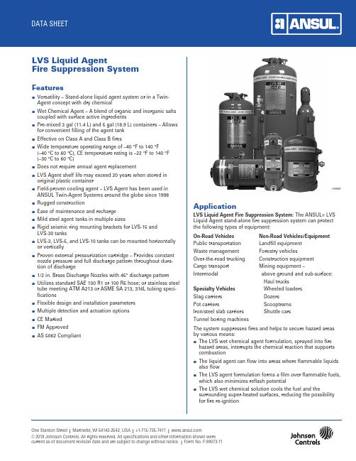
One Stanton Street | Marinette, WI 54143-2542, USA | +1-715-735-7411 | © 2018 Johnson Controls. All rights reserved. All specifications and other information shown were current as of document revision date and are subject to change without notice. | Form No. F-99073-11LVS Liquid AgentFire Suppression SystemFeaturesn V ersatility – Stand-alone liquid agent system or in a Twin-Agent concept with dry chemicaln W et Chemical Agent – A blend of organic and inorganic saltscoupled with surface active ingredientsn P re-mixed 3 gal (11.4 L) and 5 gal (18.9 L) containers – Allowsfor convenient filling of the agent tankn E ffective on Class A and Class B firesn W ide temperature operating range of –40 °F to 140 °F(–40 °C to 60 °C), CE temperature rating is –22 °F to 140 °F (–30 °C to 60 °C)n D oes not require annual agent replacementn L VS Agent shelf life may exceed 20 years when stored inoriginal plastic containern F ield-proven cooling agent – LVS Agent has been used inANSUL Twin-Agent Systems around the globe since 1998n R ugged constructionn E ase of maintenance and recharge n M ild steel agent tanks in multiple sizesn R igid seismic ring mounting brackets for LVS-15 andLVS-30 tanksn L VS-3, LVS-5, and LVS-10 tanks can be mounted horizontallyor verticallyn P roven external pressurization cartridge – Provides constantnozzle pressure and full discharge pattern throughout dura-tion of dischargen 1/2 in. Brass Discharge Nozzles with 45° discharge pattern n U tilizes standard SAE 100 R1 or 100 R5 hose; or stainless steeltube meeting ATM A213 or ASME SA 213, 316L tubing speci-ficationsn F lexible design and installation parameters n M ultiple detection and actuation options n C E Marked n F M Approved n A S 5062 Compliant009597ApplicationLVS Liquid Agent Fire Suppression System: The ANSUL ® LVSLiquid Agent stand-alone fire suppression system can protect the following types of equipment:On-Road Vehicles Non-Road Vehicles/Equipment Public transportation Landfill equipment Waste management Forestry vehicles Over-the-road trucking Construction equipment Cargo transport Mining equipment –Intermodal above ground and sub-surface:Haul trucks Specialty Vehicles Wheeled loaders Slag carriers Dozers Pot carriersScooptrams Iron/steel slab carriers Shuttle carsTunnel boring machinesThe system suppresses fires and helps to secure hazard areas by various means:n T he LVS wet chemical agent formulation, sprayed into fire hazard areas, interrupts the chemical reaction that supports combustionn T he liquid agent can flow into areas where flammable liquidsalso flown T he LVS agent formulation forms a film over flammable fuels,which also minimizes reflash potentialn T he LVS wet chemical solution cools the fuel and thesurrounding super-heated surfaces, reducing the possibility for fire re-ignitionApplication (Continued)Twin-Agent System: The fire suppression system can alsobe used as a dry chemical/liquid agent twin-agent systemfor the protection of large non-road construction and mining equipment.Off-road Vehicles/ Specialty andEquipment Underground MiningLarge excavators/shovels Slag, pot, and/or slab carriers Draglines Tunnel boring machinesHaul trucks Waste management equipment Wheeled loaders Forestry vehiclesWhen the LVS liquid agent system is used in a twin-agent system, the dry chemical portion is primarily responsible for quick fire knockdown and suppression. And although the LVS wet chemical system has similar fire suppression capabilities, the wet chemical solution utilized in a twin-agent concept is primarily intended for cooling.DescriptionThe LVS Liquid Agent Fire Suppression System is either a stand-alone fire suppression system or a Twin-Agent System when combined with an ANSUL A-101 Dry Chemical System. The LVS Liquid Agent system is designed for fire suppression and/or surface area cooling in the protected hazard areas.LVS Liquid Agent Fire Suppression System: The liquid agentis a pre-mixed proprietary solution of LVS wet chemical. The agent discharges through hydraulic hose or stainless steel tube arranged in certain straight-line configurations, depending on tank size.LVS System Parameters per Tank SizeAvg. Noz. Single Nozzle Agent Qty. Max. Discharge Coverage Area Tank gal (L) Noz. Time-Sec. ft2 (m2) LVS-3 3 (11.4) 6 20 3 (0.28) LVS-5 5 (18.9) 4 30 7 (0.65) LVS-10 10 (37.9) 8 40 7 (0.65) LVS-15 15 (56.8) 10 60 7 (0.65) LVS-30 30 (113.6) 20 60 7 (0.65) The system is designed to operate within a temperature range of –40 °F to 140 °F (–40 °C to 60 °C), CE temperature rating is–22 °F to 140 °F (–30 °C to 60 °C).The LVS wet chemical can be stored at temperatures as low as –60 °F (–51 °C).Twin-Agent System: The fire suppression system consists of both dry chemical and liquid agent. The dry chemical portion of the system is the ANSUL A-101/LT-A-101 or LT-A-101-50/125/250 system and the liquid agent portion of the system consists of an LVS-3, LVS-5, LVS-10, LVS-15, or LVS-30 tank(s).The twin-agent system, consisting of dry chemical and liquid agent, is designed to operate within a temperature range of–40 °F to 140 °F (–40 °C to 60 °C), CE temperature rating is –22 °F to 140 °F (–30 °C to 60 °C).Wet Chemical: LVS wet chemical is a unique blend of organic and inorganic salts, coupled with surface active agents. This blend provides a strong measure of freeze protection along with the foaming properties associated with conventional Class B liquid agents.The wet chemical is shipped in 3 gal (11.4 L) or 5 gal (18.9 L) plastic containers.Tank: The LVS tank is constructed of steel, finished with a red corrosion-resistant paint. A nitrogen cartridge equipped witha pneumatic actuator supplies the required expellant gas. The LVS-3, LVS-5 and LVS-10 tanks are capable of vertical or hori-zontal mounting.Nozzles: The 9.5 nozzle is a non-aspirating nozzle, constructed of brass, with a blue rubber blow-off cap that differentiates the LVS nozzles from dry chemical nozzles when used in a twin-agent system.Detection and Control: The detection and control system utilized with the LVS system is the approved ANSUL CHECKFIRE Electric Detection and Actuation System. The system is composed of components which are combined to provide automatic fire detection and actuation. The system is particularly suited for protection of equipment that is subjected to extreme environ-mental and physical c onditions.Ordering InformationPart No. Description438821 L VS-30 Shipping Assembly Consisting of: (438839)* LVS-30 Tank55 ft3 (1.6 m3) Nitrogen Cartridge with PneumaticActuatorExpellant Gas HoseTwo 1/4 in. Street Elbows438775 L VS-15 Shipping Assembly Consisting of: (438838)* LVS-15 Tank23 ft3 (0.7 m3) Nitrogen Cartridge with PneumaticActuatorExpellant Gas HoseTwo 1/4 in. Street Elbows439361 LVS-10 Shipping Assembly Consisting of:LVS-10 TankBracket435876 LVS-5 Shipping Assembly Consisting of:LVS-5 TankBracketNote: LVS-10 and LVS-5 require LT-A-101-30 Nitrogen Cartridge, Bracket, and Electric-Pneumatic Actuator Shipping Assembly, Part No. 24883 (41735)*441774 LVS-3 Shipping Assembly Consisting of:LVS-3 TankBracketNote: LVS-3 requires LT-30-R Nitrogen Cartridge, Bracket, and Electric-Pneumatic Actuator, Part No. 442586 (442587)*24883 LT-A-101-30 Nitrogen Cartridge, Bracket, and Electric- (431735)* P neumatic Actuator Shipping Assembly(LVS-5/LVS-10)433325 9.5 Nozzle Assembly (1/2 in. NPT) Consisting of:Nozzle with Blow-Off Cap“L” Mounting BracketTwo Lockwashers438835 Distribution Manifold Block (4 outlets)438834 Distribution Manifold Block (2 outlets on2 opposing sides)428405 Mounting Ring (for LVS-30)428404 Mounting Ring (for LVS-15)433685 LT-A-101-50/LVS-5 Bracket433294 9.5 Nozzle (1/2 in. NPT) with Blow-Off Cap (Single) 434403 9.5 Nozzle Blow-Off Cap (Package of 50)441775 LVS Wet Chemical, 3 gal (11.4 L) Pail426961 LVS Wet Chemical, 5 gal (18.9 L) Pail428061 55 ft3 (1.6 m3) Nitrogen Cartridge (for LVS-30) 428060 23 ft3 (0.7 m3) Nitrogen Cartridge (for LVS-15) 423491 LT-A-101-30 Nitrogen Cartridge (for LVS-5/LVS-10) (428442)*423425 LT-30-R Nitrogen Cartridge (for LVS-3)(428441)*16511 Fill Cap Spanner Wrench (LVS-5/LVS-10)428363 Sealed Burst Disc Assembly Package (15 Discs) 427560 System Blow-Down Kit427109 M anual: Installation, Operation, Design, Maintenance, and Recharge53081 Owner’s Manual*CE Version Part No. in parenthesesSpecifications1.0 General1.1 Requirements1.1.1 T he equipment to be protected shall utilize a [freeze-protected stand-alone liquid agent system] [twin-agent fire suppression system incorporating botha dry chemical and a wet chemical system] and anapproved automatic detection system.1.1.2 T he fire detection/suppression system shall consistof the following ANSUL com p onents or approvedequal:n[LVS liquid agent fire suppression system (wetchemical only)]n[LVS liquid agent/LT-A-101 dry chemical firesuppression system (twin-agent system)]n C HECKFIRE electric detection and actuationsystem1.1.3 A s backup to the fire detection/suppression system,the equipment shall contain a minimum of two 20 lbhand portable fire extinguishers.1.1.3.1 E ach hand portable extinguisher shall be aRED LINE cartridge-operated dry chemicalmodel or approved equal.2.0 Products2.1 T he [liquid agent] [twin-agent] fire detection/suppressionsystem shall be supplied as a pre-engineered system,requiring specific design (by trained and authorized person-nel) for the vehicle intended to be protected. The pre-engineered system shall consist of components includingagent storage tanks, expellant gas cartridges/containers,discharge nozzles, agent distribution lines, actuation andexpellant gas lines, an ANSUL CHECKFIRE control module, manual/automatic and manual-only actuators, and a detec-tion network that may include thermal detection alone orcombined with infra-red (IR³) flame detection.2.1.1 T he ANSUL CHECKFIRE control module shallrespond to electrical input from the detectionnetwork and initiate an output(s) for alarm, vehicleshutdown, and fire suppression system a ctuationfunctions. The control module power source shallbe provided from a 12 to 24 VDC source (by others)and/or a replaceable internal lithium battery that willsupply power for one year under normal operatingconditions. The control module shall be program-mable for alarm-to-shutdown and shutdown-to-discharge delays. The module cover shall containaudible and visual status indicators for power,alarm, detection, and release circuits.2.1.2 T he system shall provide both a manual and auto-matic means to pneumatically a ctuate the firesuppression systems.2.1.3 T he system shall provide heat detection using[linear detection wire] [spot detectors] [IR3 detec-tion] when minimal detection response times areessential.2.1.4 A gent storage shall consist of one or more steelpressure vessels each capable of being easilyinspected for agent condition and fill level withoutrequiring d epressurization.2.1.5 E ach wet chemical storage tank shall be pressur-ized upon actuation from a separate steel nitrogencylinder meeting [DOT 3AA-1800] [DOT-3AA-2015][Transport Canada] [CE] specifications.2.1.6 E ach dry chemical storage tank shall be pressurizedfrom a separate steel nitrogen cartridge meeting[DOT-3AA-1800] [DOT-3AA-2015] [Transport Canada][CE] specifications.2.1.7 T he wet chemical and dry chemical agents shallbe distributed through [SAE 100 R1] [SAE 100 R5]minimum rated hydraulic hoses or stainless steeltube meeting ATM A213 or ASME SA 213, 316Ltubing specifications, and brass n ozzles that arepermanently installed in the hazard areas. Thenozzles shall employ blow-off caps that shall beeasily displaced upon agent discharge.2.1.8 T he wet chemical shall be a blend of inorganicsalts s uitable for Class A and B fires and is freezeprotected to and can be stored at –60 °F (–51 °C).2.1.9 T he dry chemical shall be monoammonium phos-phate suitable for Class A, B, and C fires.2.1.10 T he liquid agent system shall be capable of operat-ing within a temperature range of –40 to 140 °F(–40 to 60 °C), CE temperature rating is –22 °F to140 °F (–30 °C to 60 °C).2.1.11 T he dry chemical system shall be capable of operat-ing within a temperature range of –65 to 210 °F(–54 to 99 °C).2.2 T he hand portable fire extinguisher shall consist of a mildsteel pressure vessel capable of being easily inspectedfor agent condition and fill level without requiring depres-surization. Upon operation, it shall be pressurized from aseparate steel nitrogen cartridge meeting [DOT 3A-2100][DOT 3E-1800] [Transport Canada] [CE] specifications. Theextinguishing agent shall be mono a mmonium phosphatedry chemical suitable for Class A, B, and C fires.Safety Data Sheets (SDS) are available at Note: The converted values in this document are provided for dimensional reference only and do not reflect an actual measurement.ANSUL and the product names listed in this material are marks and/or registered marks. Unauthorized use is strictly prohibited.。
APC Symmetra LX UPS 说明书
这是安全提醒符号。它用于提醒您注意潜在的人身伤害危险。请遵守带有这个符号的所有安 全消息,以避免可能的伤害或死亡。
危险
“ 危险 ” 表示存在危险情况,如果不避免,将会导致死亡或严重伤害。
警告
“ 警告 ” 表示存在危险情况,如果不避免,可能导致死亡或严重伤害。
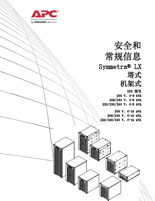
安全和 常规信息
Symmetra® LX 塔式
机架式
UPS 型号 200 V,4-8 kVA 208/240 V,4-8 kVA 220/230/240 V,4-8 kVA
200 V,4-16 kVA 208/240 V,4-16 kVA 220/230/240 V,4-16 kVA
ቤተ መጻሕፍቲ ባይዱ 重要安全信息
–国家 / 地区的当地支持中心:请访问 /support/contact 获取联系信息。
–有关如何获得当地客户支持的信息,请联系 APC by Schneider Electric 代表或您从其购买 APC by Schneider Electric 的其他分销商。
© 2018 APC by Schneider Electric 版权所有。APC、APC 徽标、Smart-UPS 和 Symmetra 均属 Schneider Electric Industries S.A.S. 或其附属公司所有。所有其他商标均为其各自所有者的财
息。
电气安全
• 在切断电源之前,请勿接触任何金属连接器。 • 对于具有硬线输入的型号,必须由合格的电工执行与分支电路 (主电源)的连接。 • 仅限 230 V 型号:为了符合 EMC 指令以便产品可以在欧洲销售,连接到 UPS 的输出电线的长度不得超过
海洋控制KTA-223 USB可扩展的控制器说明书

Ocean Controls KTA-223 Arduino Compatible USB Relay Controller•8 Relay Outputs 5A 250VAC• 4 Opto-Isolated Inputs 5-30VDC• 3 Analog Inputs (10 bit)•Connections via Pluggable Screw Terminals•0-5V or 0-20mA Analog Inputs, Jumper Selectable•5A Relay Switching•Power Indicator LED•All enclosed in Professional looking plastic case•Arduino Compatible•Accepts Arduino Shields (Ethernet / XBEE)•USB Virtual COM or RS485 Input•Easily connect multiple units far apart by RS485The KTA-223 is a USB or RS485 controlled IO module for interfacing PCs to real world applications, such as controlling lights and sprinkler systems, reading sensors and monitoring switches and other digital signals. The Relays are capable of switching up to 5A at 250VAC, 10A at 120VAC and 10A at 24VDC but the PCB tracks will only handle up to about 5A. A simple ASCII protocol allows control from Windows/Mac/Linux using either USB Virtual COM drivers or RS485. Additionally, multiple devices can be connected to one RS485 bus, allowing control of many devices from one USB port.The controller is based on the hardware of the Arduino physical computing controllers. It can be programmed as a stand-alone controller using the free, open source Arduino environment. Internally, the controller is “shield-compatible”, allowing the use of many extension boards designed for the Arduino Deumilanove. As shipped the controller is loaded with a sketch that receives simple commands over the USB or RS485 serial port and switches relays or responds with the status of inputs. This sketch is available on the Ocean Controls website as an example of Arduino programming for the controller.Multiple controllers can be connected to one or more PCs in an RS485 network. Each controller can be assigned an address and will respond to commands addressed to them.Figure 1 - Connecting multiple controllers with a RS485 networkConnectionsTable 1 - ConnectionsLabel Description Label Description+ Opto-Isolated Input Positive 5VO5V Output for Sensors- Opto-Isolated Input Negative V+12V Power Supply Positive InputANx Analog Input x COM Common Connection (Ground)COM Common Connection (Ground) USB USB B-type connection to PCD+ RS485 Data+ NO Relay Normally Open ContactD- RS485 Data- C Relay Common ContactNC Relay Normally Closed ContactSpecificationsPower Supply V+ and COM:KTA-223: 9-16V DC (12V Nominal) ~200mA + External 5V drainKTB-223: 18-32V DC (24V Nominal) ~200mA + External 5V drainAnalog Input ANx:0-5V: ~500kΩ effective resistance with no jumper installed0-20mA: ~250Ω effective resistance with jumper installedOpto-Isolated Input: 0-30V, ~1kΩ effective resistanceRelay Outputs: SPDT relays rated to 5A (resistive). 250VAC / 30VDC5V Auxiliary Supply 5V: 200mAJumper SettingsThe Analog inputs of the KTA-223 can be set for 0-5V or 0-20mA operation. Opening the case and inserting jumper shunts in the positions J1, J2 or J3 will set the associated analog inputs to 0-20mA operation. Removing the shunts will set the analog inputs to 0-5V operation.The Analog inputs are protected with 4.7kΩ inline resistors, this will protect the microcontroller from damage for accidental input voltages up to 30V.When the jumper labeled AUTO RESET is installed the board will reset each time a serial connection is made to the USB COM port. This should only be installed when reprogramming via the Arduino Environment, or the device will reset each time a serial connection is made to the unit.Using the ControllerThe controller requires 12VDC or 24VDC to operate, connected to V+ and COM.T his can come from a plug-pack, bench top power supply or battery. The controller has screw terminals for the connection of power. Plug-pack power supplies often come with a plug on the end of the lead. The plug can be cut off and bare wires exposed for the screw terminals on the controller.Connect the power supply positive connects to the V+ terminal and negative to the COM terminal next to it. The POWER LED should light. A diode protects the controller and prevents it from operating with power connected in reverse polarity. If the LED does not light, ensure your supply is delivering sufficient voltage and is connected correctly.Connect the controller to a computer using a USB A male to USB B male cable. When the power is turned on your computer may prompt you to install drivers. The drivers required are the FTDI Virtual COM Port Drivers the latest versions for all systems are available from /Drivers/VCP.htmTest UtilityThe main window of the Windows test utility is shown here.If the Address of the unit you wish to control is known put it inthe “Address” text box, if not, use 0 for the address and any unitwill respond.Enter the COM Port number in the “Port” text box, if this is notknown it can be found in the device manager under ports. Thequickest way to run device manager is by clicking Start->Runand then typing “devmgmt.msc”.Once the device is communicating, Relays can be turned on oroff by clicking the buttons in the Relays group and the status ofthe Digital and Analog Inputs are shown in their relevant groups.The source code for this program is available from OceanControls and is written in Visual Basic Express 2008 which isavailable free from Microsoft.Ocean Controls can also supply a similar example program withsource code for Visual Basic 6.Communicating with the ControllerThe Address and Baud Rate of the unit can be set and are stored in the controller ʼs memory. By default thecontroller is listening for serial data at 9600 baud, and has address 00. The controller will always use 1 Stop Bit, 8 Data Bits and No Parity.The commands the controller uses are in the form@AA CC X<CR>The @ symbol is used to define the start of a command.AA is the address of the unit from 00 to 99.CC is a two letter command used to determine the command type.X is a one or more characters which determines the parameter for the command.<CR> is the carriage return character. This is ASCII character 13, or 0x0d.Each time a valid command is received the unit will respond with #AA followed by any values that are requested from the unit.Note that 00 is the Wildcard Address, if a command has 00 as the address, all devices will respond as if they have been individually addressed.Figure 2 - Windows Test UtilityTable 2 - Command setLetter Command ParametersON Turn Relay On 1-8: Turn Relay 1-8 On Individually0: Turn All Relays On at OnceOF Turn Relay Off 1-8: Turn Relay 1-8 Off Individually0: Turn All Relays Off at OnceWR Write to all Relays at once The parameter is a number which determines which of therelays should be turned on or off.RS Status of Relays 1-8: Returns Status of Relays 1-8 Individually0: Returns Status of All RelaysIS Status of Inputs 1-4: Returns Status of Inputs 1-4 Individually0: Returns Status of All InputsAI Read Analog Input 1-3: Read Value of Analog Input 1, 2 or 30: Returns Value of All Analog InputsSA Set Address 01-99: Sets the Address of the unit in MemorySB Set Baud Rate 1-10: Sets the Baud Rate1: 1200 baud 6: 19200 baud2: 2400 baud 7: 28800 baud3: 4800 baud 8: 38400 baud4: 9600 baud (default) 9: 57600 baud5: 14400 baud 10: 115200 baudON: Relay On CommandThis command is used to turn a single relay on. E.g.: @44 ON 1 will turn relay 1 on for the unit with address 44. It can also be used to turn all the relays on, this occurs when the parameter value is 0.OF: Relay Off CommandSimilar to the on command this command will turn relays off in the same manner. E.g.: @44 OF 1 will turn relay 1 off for the unit with address 44, @44 OF 0 will turn all relays off.WR: Write Relays CommandThe write relays command is used when more than one relay is to be turned on or off at once. The parameter is a decimal number which, in binary, represents the on and off status of the 8 relays. The least significant bit of this value controls relay 1. The most significant bit of the parameter value controls relay 8. A set bit (1) turns the relay on, a cleared bit (0) turns the relay off.Example: To turn relays 1, 2 and 6 on (and others off) the binary value required is 00100011. In decimal this is 35. (2^(1-1) + 2^(2-1) + 2^(6-1) = 35). To issue this to a controller with address 44, the required command is @44 WR 35IS: Input Status CommandThis command will return the status of the inputs. If the parameter is between 1 and 4 then the controller will return a 0 or 1 corresponding to that input. E.g.: @44 IS 1 will return #44 1 if the input is on, or #44 0 if the input is off.If the parameter is 0 then the unit will respond with the status of all the inputs, in similar form as the Write Relays command. E.g.: If inputs 1 and 2 for the unit are on then @44 IS 0 will return #44 3. 3 is 0011 in binary, and each bit represents each input from 4 down to 1.RS: Relay Status Command:Much the same as the input status command, this command will return the status of the relays. If the parameter is between 1 and 8 then the unit will return with a 0 or 1 corresponding to that relay. E.g.: @44 RS 1 will return #44 1 if the relay is on, or #44 0 if the relay is off.If the parameter to this command is 0 then the unit will respond the same way as the input status command, but return the status of the relays.AI: Analog Input CommandThe analog input command will read the status of the analog input defined by the parameter and return it as a value between 0 and 1023. E.g.: @44 AI 1 will return #44 512 if the analog input is reading 50%.SA: Set AddressAddresses are valid from 01-99. A unit will only respond if its address in memory is the same as that of the command sent, or if the address of the command sent is 00. The address is saved to non-volatile memory inside the controller, meaning it will be preserved even after power is disconnect from the controller.SB: Set BaudParameters from 1 to 10 are valid, corresponding to values shown in Table 3.Table 3 - Baud rate selection1: 1200 baud 6: 19200 baud2: 2400 baud 7: 28800 baud3: 4800 baud 8: 38400 baud4: 9600 baud (default) 9: 57600 baud5: 14400 baud 10: 115200 baudThe baud rate is saved to non-volatile memory inside the controller, meaning it will be preserved even after power is disconnect from the controller.Using the Controller as an ArduinoThe KTA-223, as supplied, is an Arduino compatible board with Arduino bootloader and a custom sketch loaded that responds to the serial commands listed above. The source code of this is available from Ocean Controls and can be modified in the Arduino environment to suit your purpose.The Arduino programming environment can be downloaded for Windows, Mac OS X and Linux from/When using the KTA-223 with the Arduino Environment select “Arduino Duemilenove w/ ATmega328” from the “Tools->Board” menu, and install the “AUTO RESET” jumper on the PCB for ease of programming.The hardware has been designed to accept the Arduino compatible Shields. The cover may not be able to be installed when using larger shields. Some shields may require removal or modification of the back panel to fit over-hanging components (The Libelium XBee shield fits with XBee modules using chip antennae, but SMA antenna connections conflict with the back panel)The V1 controller PCB does not locate the 6-pin ICSP in the same position as the Arduino Deumillanove. Some shields (notably the Libelium XBee shield) take 5V power, ground or other signals from the ICSP header. These shields must be supplied power or signals from the standard Arduino header rows, or extended from the ICSP connection on the controller the the shield.The the Libelium XBee shield must be supplied with 5V power by connecting 5V on the shield to K6 Pin 2 and GND on the shield to K6 Pin 6.Space is provided on the PCB to install the SparkFun Real Time Clock module (SparkFun SKU: BOB-00099). The intention is to allow the controller to operate in stand alone situations that require more timing flexibility than the stock controller can provide. The PCB connects the RTC module SDA to Arduino Digital 12 and SCL to Arduino Digital 13. Installing this unit may prevent proper operation of other modules or shield that rely on these pins (for example, the Ethernet shield cannot be used with the RTC module.)The RS485 transceiver is connected in parallel with the FTDI USB to Serial converter and ATMega328 UART pins. This transceiver allows half-duplex serial communication over 2 or 3 wires. The transceiver requires a TX Controlsignal to enable the transmit or receive line driver. When transmitting, the TX Control line must be asserted (driven high). To receive, the line must be left low.The FT232RL USB to Serial converter provides a TXEN signal for RS485 Transceivers. When data is received from the USB port by the FT232RL, it asserts the TX Control line, putting the RS485 transceiver in Transmit mode. The serial data is then transmitted to the ATMega328 and onto the RS485 network.Using the RS485 transceiver from custom Arduino code requires that your code drive the TX Control line high at the beginning of data transmission and returns it low at the end of the transmission. The TX Control line is connected to Digital 19. The Ocean Controls sketch provides an example of how to do this.Table 4 shows the mapping of Arduino pins to the inputs and outputs of the controller.Table 4 - Arduino Pin MappingKTA-223 IO Arduino Pin AVR Port.PinRelay 1 Digital 2 PORTD.2Relay 2 Digital 3 PORTD.3Relay 3 Digital 4 PORTD.4Relay 4 Digital 5 PORTD.5Relay 5 Digital 6 PORTD.6Relay 6 Digital 7 PORTD.7Relay 7 Digital 8 PORTB.0Relay 8 Digital 9 PORTB.1Opto-In 1 Digital 15 / Analog 1 PORTC.1Opto-In 2 Digital 16 / Analog 2 PORTC.2Opto-In 3 Digital 17 / Analog 3 PORTC.3Opto-In 4 Digital 18 / Analog 4 PORTC.4Analog In 1 Analog 6 ADC6Analog In 2 Analog 7 ADC7Analog In 3 Analog 0 PORTC.0RX Data Digital 0 PORTD.0TX Data Digital 1 PORTD.1RS485 TX Control Digital 19 / Analog 5 PORTC.5Ethernet Shield Digital 10 PORTB.2Ethernet Shield Digital 11 PORTB.3Digital 12 PORTB.4Ethernet Shield / RTCSDAEthernet Shield / RTCDigital 13 PORTB.5SCLWiring Examples: InputsThe opto-isolated inputs allow for a range of connection possibilities. The figures below show the wiring for a dry-contact switch, NPN and PNP-type sensor.Figure 3 - Wiring a dry contact switchFigure 4 - Wiring an NPN-type sensorFigure 5 - Wiring a PNP-type sensorAnalog inputs can be wired for 0-5V or 0-20mA signals, depending on the position of the input jumper inside the unit. A regulated 5V output is provided for the convenience of wiring analog sensors like potentiometers.Figure 6 - Wiring a potentiometerFigure 7 - Wiring a 4-20mA, loop-powered sensorWiring Examples: OutputsThe relay outputs on the KTA-223 can be wired to DC or AC loads.Figure 8 - Wiring a basic DC loadInductive loads at high currents cause large voltage spikes when turned on or off, and this can disrupt sensitive electronics. For large inductive loads, a snubber is recommended. A DC load can be bypassed with a circulation diode. An AC load requires an RC snubber across the relay contacts. Ensure that diodes, resistors and capacitors used for snubbers are correctly rated for the load and voltage being switched.ErrataThe V1 PCB requires a link to be installed from R8 (pad furthest from MAX48) to the via closest to MAX485 Pin 5. This will have been installed by Ocean Controls on boards purchased through them or a distributor.Selection GuideLicensingThe KTA-223 is derived from the Arduino Deumilanove and the schematics and CAD files are available under Creative Commons Attribution Share-Alike licenses. Contact **********************.au for more information.。
SCALANCE X101-1 商品说明书
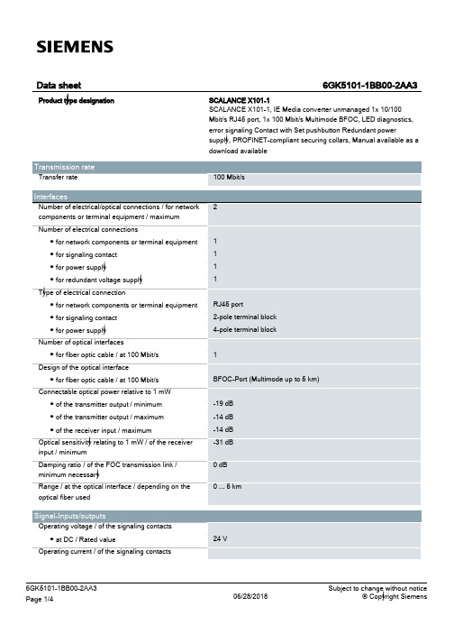
24 V
6GK5101-1BB00-2AA3 Page 1/4
06/28/2018
Subject to change without notice © Copyright Siemens
● at DC / maximum
Supply voltage, current consumption, power loss Supply voltage ● external ● external Type of voltage / of the supply voltage Product component / fusing at power supply input Fuse protection type / at input for supply voltage Consumed current ● maximum Power loss [W] ● at DC / at 24 V
Compact 40 mm 125 mm 124 mm 0.55 kg
Yes Yes Yes
No No
FM3611: Class 1, Divison 2, Group A, B, C, D / T.., Class 1, Zone 2, Group IIC, T.. EN 600079-15 II 3 G EEx nA II T.. KEMA 06 ATEX 0021 X
Yes
Yes Yes Yes Yes Yes No 134 y
/snst
/simatic-net https:// /industry/infocenter /bilddb /cax https://
Security information
UL 60950-1, CSA C22.2 No. 60950-1 UL 1604 and UL 2279-15 (Hazardous Location), Class 1 / Division 2 / Group A, B, C, D / T.., Class 1 / Zone 2 / Group IIC / T.. EN 61000-6-3 EN 61000-6-4:2001 EN 61000-6-2:2001, EN 61000-6-4:2001 Yes Yes Yes
2KAX原厂中文规格书
Rev. 1.1
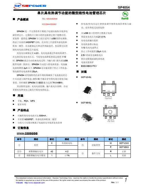
■ 功能框图
SP4054
■ 电学特性参数
输入电压
参数
输入电流
输出控制电压
BAT端电流
涓流充电电流
标号 Vcc Icc Vfloat
Ibat
Itrikl
条件
Charge mode,Rprog=10K Standby mode Shutdown mode(Rprog not connected,Vcc<Vbat or Vcc<Vuv) 0℃<TA<85℃, IBAT = 40mA Rprog=10k,Current mode Rprog=2k,Current mode Standby mode,Vbat=4.2V Shutdown mode Battery reverse mode, VBAT=-4V Sleep mode,Vcc=0V Vbat<Vtrikl,Rprog=2k
■ 封装
SOT-23-5L
5
4
PROG
VCC
SOT-89-5L
CHRG GND BAT
12 3
SOT-23-5L (Top View)
5
4
PROG PROG
VCC
CHRG GND BAT
1 23 1 SOT-829-5L 3
(Top View)
SP4054 ①②③④⑤⑥
标号 ① ②③ ④
描述 类型
Rev. 1.1
涓流充电极限电压 涓流充电迟滞电压 电源低电闭锁阈值电压 电源低电阈值电压迟滞电压 手动关闭阈值电压
Vcc-Vbat停止工作阈值电压
C/10 终端阈值电流 PROG端电压 CHRG端弱下拉电流 CHRG端最小输出电压 电池再充电迟滞电压
AXP223中文

版本历史
版本 1.0 1.1
日期 2013.08.30 2013.11.28
描述 第一版 修改部分参数,补充寄存器说明
版权声明
版权所有,违法必究。
非经本公司书面同意,任何单位或个人不得擅自摘抄、复制本文档内容的部分或全部,并不得以任何形式进行传播。任何单位或个人不得 删除、修改或移除本文档版权及所有的权利声明。
功能框图 ............................................................................................................................................................................................................ 12
9.5.
E-Gauge ™ 电量计系统 ............................................................................................................................................................. 27
10.2. 寄存器描述 ......................................................................................................................................................................................32
货物需求一览表
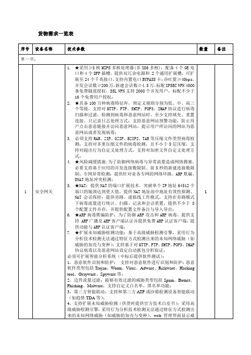
货物需求一览表序号设备名称技术参数数量备注第一项:1 安全网关1.★采用≥3核MIPS多核处理器(非X86多核);配备4个GE电口和4个SFP插槽,提供双冗余电源和 2个通用扩展槽,可扩展至24个千兆接口,支持内置电口BYPASS卡;吞吐量≥4Gbps,并发会话数≥200万,新建会话数≥4.5万。
标配IPSEC VPN 4000条免费隧道授权,SSL VPN支持2000个并发用户,标配不少于16个免费用户授权;2.★具备100万种病毒特征库,预定义规则分别为低、中、高三个等级,支持对HTTP、FTP、SMTP、POP3、IMAP协议进行病毒扫描和过滤,检测到病毒和恶意网站时,至少支持填充、重置连接、只记录日志处理方式;支持恶意网站预警功能,防止用户点击恶意链接并访问恶意网站,提示用户所访问的网站为恶意网站或者发现病毒;3.必须支持RAR、ZIP、GZIP、BZIP2、TAR等压缩文件类型病毒检测;支持对多重压缩文件的病毒检测,且不小于5层压缩,支持对超出行为自定义处理方式,支持对加密文件自定义处理方式;4.★风险减缓措施:为了防御网络病毒与异常流量造成网络拥塞,必要支持基于应用的并发连接数限制、前5秒的新建连接数限制;专网异常检测:提供针对业务专网的网络环路、ARP欺骗、SNAT地址冲突检测;5.★NAT:提供NAT的端口扩展技术,突破单个IP地址64512个端口的瓶颈达到更大值,提供NAT地址池中地址有效性探测、NAT 会话保持;提供旁路、虚拟线工作模式,支持在旁路模式下病毒流量进行统计、扫描、记录和会话重置,提供不少于8个配置文件并存,并提供配置文件备注与导入导出;6.★ARP病毒欺骗防护:为了防御ARP攻击和ARP病毒,提供支持 ARP广播及ARP客户端认证并提供免费ARP认证客户端,提供功能与ARP认证客户端;7.★扩展未知威胁检测功能:基于高级威胁检测引擎,采用行为分析技术检测无法通过特征方式检测出来的未知网络威胁(如威胁的加壳与变种);支持基于对HTTP、FTP、SMTP、POP3、IMAP协议病毒以及恶意网站设定自动抓包分析取证;必须可扩展智能分析系统(中标后提供软件测试):1,恶意软件识别和防护:支持对恶意软件进行识别和防护:恶意软件类型包括Trojan、Worm、Virus、Adware、Riskware、Hacking tool、Grayware、Spyware等;2,边界流量过滤:能够有效过滤的威胁类型包括Spam、Botnet、Phishing、Malware;支持自定义白名单、黑名单功能;3,第三方智能联动:支持和第三方ATP或沙箱检测设备智能联动(如趋势TDA等);4,支持扩展未知威胁检测(供货时提供官方技术白皮书):采用高级威胁检测引擎,采用行为分析技术检测无法通过特征方式检测出来的未知网络威胁(如威胁的加壳与变种),web管理界面显示威1胁证据报文显示和下载;高级威胁检测特征库为独立文件,支持自动更新和手动更新模式;5,异常行为检测(供货时提供官方异常行为分析技术白皮书):网络异常行为分析:采用异常分析检测引擎,自学习主机和服务器行为基线,自动生成上限阈值、下限阈值、实施流量、预测值等属性,根据安全基线偏离度综合异常行为特征库分析出隐藏的异常行为;6,服务器异常行为检测:针对WEB 服务器实时监测建模,自动生成上限阈值、下限阈值、实施流量、预测值等属性,根据安全基线偏离度综合异常行为特征库分析出当前的针对于Web服务器的异常行为,异常行为特征库为独立文件,支持自动更新和手动更新模式;7,风险减缓措施:支持对威胁行为自动采取减缓措施,避免威胁对业务造成严重的影响。
Ra-01S规格书说明书

Ra-01S规格书版本V1.1版权©2020免责申明和版权公告本文中的信息,包括供参考的URL地址,如有变更,恕不另行通知。
文档“按现状”提供,不负任何担保责任,包括对适销性、适用于特定用途或非侵权性的任何担保,和任何提案、规格或样品在他处提到的任何担保。
本文档不负任何责任,包括使用本文档内信息产生的侵犯任何专利权行为的责任。
本文档在此未以禁止反言或其他方式授予任何知识产权使用许可,不管是明示许可还是暗示许可。
文中所得测试数据均为安信可实验室测试所得,实际结果可能略有差异。
文中提到的所有商标名称、商标和注册商标均属其各自所有者的财产,特此声明。
最终解释权归深圳市安信可科技有限公司所有。
注意由于产品版本升级或其他原因,本手册内容有可能变更。
深圳市安信可科技有限公司保留在没有任何通知或者提示的情况下对本手册的内容进行修改的权利。
本手册仅作为使用指导,深圳市安信可科技有限公司尽全力在本手册中提供准确的信息,但是深圳市安信可科技有限公司并不确保手册内容完全没有错误,本手册中的所有陈述、信息和建议也不构成任何明示或暗示的担保。
文件制定/修订/废止履历表版本日期制定/修订内容制定核准V1.02020.8.12首版徐V1.12020.8.19更新部分参数徐目录一、产品概述 (5)二、电气参数 (6)三、外观尺寸 (8)四、管脚定义 (10)五、原理图 (11)六、设计指导 (12)七、回流焊曲线图 (14)八、包装信息 (15)九、联系我们 (15)一、产品概述安信可LoRa系列模块(Ra-01S)由安信可科技设计开发。
该模组用于超长距离扩频通信,其射频芯片SX1268主要采用LoRa™远程调制解调器,用于超长距离扩频通信,抗干扰性强,能够最大限度降低电流消耗。
借助SEMTECH的LoRa™专利调制技术,SX1268具有超过-148dBm的高灵敏度,+22dBm的功率输出,传输距离远,可靠性高。
同时,相对传统调制技术,LoRa™调制技术在抗阻塞和选择方面也具有明显优势,解决了传统设计方案无法同时兼顾距离、抗干扰和功耗的问题。
华为IT产品与解决方案彩页

在云时代,华为 IT 产品线聚焦 IT 基础设施,有力推动企业简 化 IT 系统,焕发业务敏捷活力。华为基于客户价值不断创新, 提 供服务器、存储、云计算系列产品以及数据中心解决方案。同时 秉承开放合作的理念 , 与四百多家合作伙伴携手,提供端到端的 IT 解决方案。
在 IT 转型的商业革命中, 华为以 IT 作为未来战略的增长点, 积极创新,推动变革,促进 IT 转型发展。为此, 华为投入超过 1 万人构筑 IT 能力,在深圳、西安、北京、杭州、成都等地设立研 发中心,在美国、加拿大、欧洲、俄罗斯等研究所开展 IT 技术领 域的能力布局,与业界顶尖的科研院校展开合作,不断增强创新 能力和核心竞争力。
文件共享 视频监控 虚拟化 灾备
双活
高性能计算 检索 分析
媒体
数据库性能加速
DeviceManager ( 设备管理 )
DJ (融合数据管理)
CloudDrive (数据服务 )
软 件 产 品
Smart 系列 ( 数据智能控制 )
Hyper 系列 ( 数据保护控制 )
Info 系列 ( 海量数据控制 )
产
统一存储
品
5600 V3/5800 V3 •• 2~8 控制器 •• 最大 1TB Cache •• 最大 1,250 块硬盘
6800 V3/6900 V3 •• 2~8 控制器 •• 最大 4TB Cache •• 最大 2,000 块硬盘
海量存储
18500/18800
Dorado 2100 G2 Dorado 5100
2014/10/29 15:40:04
CONTENTS
01/ 华为 OceanStor 全景图 02/ OceanStor V3 系列融合存储:让业务更敏捷
MacroSAN MS5520G2-HG 系列存储设备安装手册说明书
MacroSAN MS5520G2-HG系列存储设备安装手册文档版本:V1.01杭州宏杉科技股份有限公司400-650-5527声明版权所有©2022杭州宏杉科技股份有限公司。
保留所有权利。
未经杭州宏杉科技股份有限公司书面许可,任何单位和个人不得擅自摘抄本手册的内容,且不得以任何形式传播本手册。
本手册仅作为操作参考,由于软件版本升级或其他原因,本手册的内容可能滞后于最新的软件版本或设备配置,杭州宏杉科技股份有限公司保留在没有任何通知或提示的情况下对本手册的内容进行修改的权利。
商标信息MacroSAN、ODSP、ODSP_MSC、ODSP_JMC、ODSP Scope、宏杉均为杭州宏杉科技股份有限公司的商标。
对于本手册中出现的其他公司的商标、产品标识及商品名称,由各自权利人拥有。
目录MacroSAN MS5520G2-HG系列存储设备 ............................................................................................ 1-1安装手册............................................................................................................................................... 1-1声明 ...................................................................................................................................................... 1-2商标信息............................................................................................................................................... 1-2目录 ...................................................................................................................................................... 1-3图目录................................................................................................................................................... 1-8表目录................................................................................................................................................. 1-12 1前言 ................................................................................................................................................. 1-141.1 读者对象.......................................................................................................................................... 1-141.2 适用范围.......................................................................................................................................... 1-141.3 文档结构.......................................................................................................................................... 1-141.4 文档约定.......................................................................................................................................... 1-151.4.1 手册描述约定........................................................................................................................ 1-151.4.2 其他约定 ............................................................................................................................... 1-161.5 术语................................................................................................................................................. 1-161.5.1 DSU ...................................................................................................................................... 1-161.5.2 EMC ...................................................................................................................................... 1-161.5.3 EP ......................................................................................................................................... 1-161.5.4 FC ......................................................................................................................................... 1-161.5.5 GE ........................................................................................................................................ 1-161.5.6 GUI ....................................................................................................................................... 1-161.5.7 iSCSI .................................................................................................................................... 1-161.5.8 ODSP ................................................................................................................................... 1-171.5.9 ODSP Scope ........................................................................................................................ 1-171.5.10 ODSP Scope+ .................................................................................................................... 1-171.5.11 SAN .................................................................................................................................... 1-171.5.12 SAS .................................................................................................................................... 1-171.5.13 SATA .................................................................................................................................. 1-171.5.14 SP ....................................................................................................................................... 1-171.5.15 SPU .................................................................................................................................... 1-171.5.16 SSD .................................................................................................................................... 1-171.6 资料获取方式................................................................................................................................... 1-181.7 资料意见或建议反馈方式 ................................................................................................................ 1-18 2设备使用注意事项............................................................................................................................ 2-182.1 用电安全注意事项 ........................................................................................................................... 2-182.2 防静电安全注意事项........................................................................................................................ 2-182.2.2 无防静电腕带时紧急操作方法............................................................................................... 2-192.3 激光安全注意事项 ........................................................................................................................... 2-192.4 电池安全注意事项 ........................................................................................................................... 2-192.5 EMC注意事项................................................................................................................................. 2-202.6 磁盘使用注意事项 ........................................................................................................................... 2-202.7 操作安全注意事项 ........................................................................................................................... 2-21 3产品介绍 .......................................................................................................................................... 3-223.1 产品概述.......................................................................................................................................... 3-223.2 产品规格.......................................................................................................................................... 3-223.2.1 SPU规格 .............................................................................................................................. 3-223.2.2 DSU规格.............................................................................................................................. 3-233.2.3 磁盘模块规格........................................................................................................................ 3-243.3 产品外观.......................................................................................................................................... 3-253.3.1 SPU外观 .............................................................................................................................. 3-253.3.2 DSU2625外观...................................................................................................................... 3-303.3.3 DSU2624外观...................................................................................................................... 3-343.3.4 DSU2725外观...................................................................................................................... 3-383.3.5 磁盘模块外观........................................................................................................................ 3-423.4 产品指示灯 ...................................................................................................................................... 3-443.4.1 SP指示灯 ............................................................................................................................. 3-443.4.2 SPU风扇模块+电池模块指示灯 ........................................................................................... 3-453.4.3 IO插卡指示灯....................................................................................................................... 3-453.4.4 DSU指示灯 .......................................................................................................................... 3-473.4.5 EP指示灯 ............................................................................................................................. 3-473.4.6 DSU风扇模块指示灯............................................................................................................ 3-483.4.7 电源模块指示灯 .................................................................................................................... 3-483.4.8 磁盘模块指示灯 .................................................................................................................... 3-48 4安装设备 .......................................................................................................................................... 4-494.1 安装规划.......................................................................................................................................... 4-494.2 安装流程.......................................................................................................................................... 4-494.3 安装前准备 ...................................................................................................................................... 4-504.3.1 准备安装场所........................................................................................................................ 4-504.3.2 准备机柜 ............................................................................................................................... 4-534.3.3 准备安装工具........................................................................................................................ 4-544.4 安装前检查 ...................................................................................................................................... 4-554.4.1 检查环境 ............................................................................................................................... 4-554.4.2 检查设备 ............................................................................................................................... 4-564.5 安装机柜.......................................................................................................................................... 4-584.5.1 安装机柜 ............................................................................................................................... 4-584.5.2 安装机柜后检查 .................................................................................................................... 4-584.6 安装托架式滑道............................................................................................................................... 4-594.6.1 托架式滑道介绍 .................................................................................................................... 4-594.6.2 确定滑道位置........................................................................................................................ 4-604.6.3 安装滑道 ............................................................................................................................... 4-604.6.4 安装滑道后检查 .................................................................................................................... 4-624.7 安装浮动螺母(可选).................................................................................................................... 4-624.7.1 浮动螺母介绍........................................................................................................................ 4-624.7.2 安装浮动螺母到机柜内 ......................................................................................................... 4-634.8 安装SPU ......................................................................................................................................... 4-634.8.1 安装SPU流程...................................................................................................................... 4-634.8.2 安装SPU到机柜中............................................................................................................... 4-644.8.3 安装SPU风扇模块+电池模块(可选)................................................................................ 4-654.8.4 安装SPU磁盘模块和磁盘假面板(可选)........................................................................... 4-664.8.5 安装SPU后检查 .................................................................................................................. 4-664.9 安装DSU......................................................................................................................................... 4-674.9.1 安装DSU流程...................................................................................................................... 4-674.9.2 安装DSU到机柜中............................................................................................................... 4-684.9.3 安装DSU磁盘模块和磁盘假面板(可选) .......................................................................... 4-684.9.4 安装DSU后检查 .................................................................................................................. 4-694.10 安装线缆........................................................................................................................................ 4-694.10.1 布线注意事项...................................................................................................................... 4-694.10.2 安装线缆流程...................................................................................................................... 4-724.10.3 安装接地线.......................................................................................................................... 4-734.10.4 安装电源线.......................................................................................................................... 4-744.10.5 安装SAS线缆 .................................................................................................................... 4-764.10.6 安装SP业务接口线缆 ........................................................................................................ 4-824.10.7 安装SP管理网口线缆 ........................................................................................................ 4-864.10.8 安装客户端服务器线缆 ....................................................................................................... 4-864.10.9 安装线缆后检查 .................................................................................................................. 4-87 5启动与配置设备 ............................................................................................................................... 5-875.1 设备上电前检查............................................................................................................................... 5-875.2 设备上电及启动............................................................................................................................... 5-885.2.1 DSU上电及启动 ................................................................................................................... 5-885.2.2 DSU启动后检查 ................................................................................................................... 5-885.2.4 SPU启动后检查 ................................................................................................................... 5-895.3 设备配置.......................................................................................................................................... 5-895.3.1 设备默认配置........................................................................................................................ 5-895.3.2 设备配置准备........................................................................................................................ 5-905.3.3 设备配置 ............................................................................................................................... 5-905.4 设备关机及下电............................................................................................................................... 5-92 6安装与拆卸设备组件 ........................................................................................................................ 6-936.1 安装与拆卸设备组件速查表............................................................................................................. 6-936.2 安装/拆卸SP ................................................................................................................................... 6-946.2.1 SP介绍................................................................................................................................. 6-946.2.2 安装SP ................................................................................................................................. 6-946.2.3 拆卸SP ................................................................................................................................. 6-956.3 安装/拆卸SPU风扇模块+电池模块................................................................................................. 6-956.3.1 SPU风扇模块+电池模块介绍 ............................................................................................... 6-956.3.2 安装SPU风扇模块+电池模块 .............................................................................................. 6-966.3.3 拆卸SPU风扇模块+电池模块 .............................................................................................. 6-966.3.4 安装电池模块到风扇模块中 .................................................................................................. 6-976.3.5 从风扇模块中拆卸电池模块 .................................................................................................. 6-976.4 安装/拆卸IO插卡............................................................................................................................ 6-986.4.1 IO插卡介绍........................................................................................................................... 6-986.4.2 安装/拆卸IO插卡 ................................................................................................................. 6-986.5 安装/拆卸EP ................................................................................................................................. 6-1006.5.1 安装/拆卸DSU2625 EP ...................................................................................................... 6-1006.5.2 安装/拆卸DSU2624 EP ...................................................................................................... 6-1016.5.3 安装/拆卸DSU2725 EP ...................................................................................................... 6-1026.6 安装/拆卸DSU风扇模块............................................................................................................... 6-1036.6.1 安装/拆卸DSU2625风扇模块 ............................................................................................ 6-1036.6.2 安装/拆卸DSU2624风扇模块 ............................................................................................ 6-1046.6.3 安装/拆卸DSU2725风扇模块 ............................................................................................ 6-1056.7 安装/拆卸电源模块 ........................................................................................................................ 6-1086.7.1 电源模块介绍...................................................................................................................... 6-1096.7.2 安装电源模块...................................................................................................................... 6-1106.7.3 拆卸电源模块...................................................................................................................... 6-1106.8 安装/拆卸磁盘模块 ........................................................................................................................ 6-1116.8.1 磁盘模块介绍...................................................................................................................... 6-1116.8.2 安装/拆卸2.5英寸磁盘模块A ............................................................................................ 6-1126.8.3 安装/拆卸2.5英寸磁盘模块B ............................................................................................ 6-1136.8.4 安装/拆卸3.5英寸磁盘模块................................................................................................ 6-1156.8.5 安装磁盘假面板 .................................................................................................................. 6-117 7常见故障处理................................................................................................................................. 7-1187.1 SP故障处理 .................................................................................................................................. 7-1187.1.1 故障现象1:SP的告警指示灯闪烁或常亮 ......................................................................... 7-1187.1.2 故障现象2:SP的运行指示灯常亮或常灭 ......................................................................... 7-1197.1.3 故障现象3:SP启动过程中,LED数码管无法显示信息................................................... 7-1197.1.4 故障现象4:SP启动过程中,LED数码管停留在88 ......................................................... 7-1197.1.5 故障现象5:SP启动过程中,LED数码管长时间停留在某个固定值................................. 7-1207.2 SPU风扇模块+电池模块故障处理 ................................................................................................ 7-1207.3 EP故障处理 .................................................................................................................................. 7-1217.3.1 故障现象1:告警指示灯闪烁或常亮 .................................................................................. 7-1217.3.2 故障现象2:运行指示灯常亮或常灭 .................................................................................. 7-1217.4 DSU风扇模块故障处理................................................................................................................. 7-1227.5 电源模块故障处理 ......................................................................................................................... 7-1227.6 磁盘模块故障处理 ......................................................................................................................... 7-1237.7 其他故障处理................................................................................................................................. 7-123附录A.拇指螺钉的安装方法.............................................................................................................. 7-123附录B.中国有害物质声明 ................................................................................................................. 7-126图目录图3-1 SPU前正视图........................................................................................................................... 3-25图3-2 SPU后正视图........................................................................................................................... 3-26图3-3 SP正视图................................................................................................................................. 3-27图3-4 SPU风扇模块+电池模块正视图................................................................................................ 3-28图3-5 SPU电池模块正视图................................................................................................................ 3-29图3-6 SPU电源模块正视图................................................................................................................ 3-29图3-7 DSU2625前正视图 .................................................................................................................. 3-30图3-8 DSU2625后正视图 .................................................................................................................. 3-31图3-9 DSU2625的EP正视图............................................................................................................ 3-32图3-10 DSU2625风扇模块正视图...................................................................................................... 3-33图3-11 DSU2625电源模块正视图...................................................................................................... 3-33图3-12 DSU2624前正视图................................................................................................................. 3-34图3-13 DSU2624后正视图................................................................................................................. 3-35图3-14 DSU2624的EP正视图 .......................................................................................................... 3-36图3-15 DSU2624风扇模块正视图...................................................................................................... 3-37图3-16 DSU2624电源模块正视图...................................................................................................... 3-37图3-17 DSU2725前正视图................................................................................................................. 3-38图3-18 DSU2725后正视图................................................................................................................. 3-38图3-19 DSU2725的EP正视图 .......................................................................................................... 3-39图3-20 DSU2725后端风扇模块正视图............................................................................................... 3-40图3-21 DSU2725内置风扇模块安装位置示意图................................................................................. 3-41图3-22 DSU2725内置风扇模块外观图............................................................................................... 3-41图3-23 DSU2725电源模块正视图...................................................................................................... 3-42图3-24 2.5英寸磁盘模块A外观......................................................................................................... 3-42图3-25 2.5英寸磁盘模块B外观......................................................................................................... 3-43图3-26 2.5英寸磁盘模块前面板 ......................................................................................................... 3-43图3-27 3.5英寸磁盘模块前面板 ......................................................................................................... 3-44图4-1存储设备的安装规划示意图 ...................................................................................................... 4-49图4-2存储设备的安装流程示意图 ...................................................................................................... 4-50图4-3设备防拆封条示意图................................................................................................................. 4-57图4-4保留磁盘标签示意图................................................................................................................. 4-58图4-5带拇指螺钉托架式滑道(左侧滑道)示意图 ............................................................................. 4-59图4-6带定位销托架式滑道(左侧滑道)示意图................................................................................. 4-60。
SCALANCE XF208 产品说明书
Product data sheet6GK5208-0BA00-2AF2 Product type designation SCALANCE XF208SCALANCE XF208, FLAT,MANAGED IE SWITCH,8 X 10/100MBIT/S RJ45 PORTS,FAULT SIGNAL CONTACT WITH SET- BUTTON,REDUNDANT POWER SUPPLY,PROFINET-IO DEVICE, NETWORKMANAGEMENT,RED.- MANAGER INTEGRATED,INCL. MANUAL ON CD, C-PLUG OPTIONALTransfer rate / 110 Mbit/sTransfer rate / 2100 Mbit/s8Number of electrical/optical connections / for network components orterminal equipment / maximumNumber of electrical connections• for network components or terminal equipment8• for signaling contact1• for power supply1• for redundant voltage supply1Design of the electrical connection• for network components or terminal equipment RJ45 port• for signaling contact2-pole terminal block• for power supply4-pole terminal blockdesign of the removable storage / C-PLUG YesOperating voltage / of the signaling contacts• for DC• Rated value24 VOperating current / of the signaling contacts• for DC• maximum0.1 AType of voltage / of the supply voltage DCSupply voltage / external24 V• minimum18 V• maximum32 VProduct component / fusing at power supply input YesFuse protection type / at input for supply voltage1,1 A / 33 VConsumed current / maximum0.13 AActive power loss / for DC / at 24 V 3.12 WAmbient temperature• during operation-40 … +60 °C• during storage-40 … +70 °C• during transport-40 … +70 °C• Note If the IE switch XF 200 is installed horizontally a maximum ambienttemperature of +40 °C is permittedRelative humidity• at 25 °C / without condensation / during operation / maximum95 %Protection class IP IP20Design FlatWidth75 mmHeight125 mmDepth73 mmNet weight0.25 kgMounting type• 35 mm DIN rail mounting Yes• wall mounting No• S7-300 rail mounting No• S7-1500 rail mounting No50Cascading in the case of a redundant ring / at reconfiguration time of<\~0.3\~sCascading in cases of star topology Any (depending only on signal propagation time)Product function• CLI Yes• web-based management Yes • MIB support Yes • TRAPs via email Yes • Configuration with STEP 7Yes • Port mirroring Yes • multiport mirroring No • with IRT• PROFINET IO switch No • PROFINET IO diagnosis Yes • switch-managed Yes Protocol / is supported• Telnet Yes • HTTP Yes • HTTPS Yes • TFTP Yes • FTP Yes • BOOTP No • DCP Yes • LLDP Yes Identification & maintenance function• I&M0 - device-specific information Yes • I&M1 – higher-level designation/location designation Yes Protocol / is supported• SNMP v1Yes • SNMP v2Yes • SNMP v3YesProduct function• Port diagnostics Yes • Statistics Packet Size Yes • Statistics packet type Yes • Error statistics YesProduct function• DHCP client YesProduct function• Ring redundancy Yes • High Speed Redundancy Protocol (HRP)Yes• high speed redundancy protocol (HRP) with redundancyYesmanager• high speed redundancy protocol (HRP) with standby redundancy No• Media Redundancy Protocol (MRP)Yes• media redundancy protocol (MRP) with redundancy manager Yes• Passive listening YesProtocol / is supported• SSH YesProduct function / SICLOCK support YesProtocol / is supported• NTP No• SNTP YesStandard• for FM FM3611: Class 1, Divison 2, Group A, B, C, D / T4, CL.1, Zone 2,GP. IIC, T4• for hazardous zone EN 60079-0: 2006, EN60079-15: 2005, II 3 G Ex nA II T4, KEMA 07ATEX 0145 X• for safety / from CSA and UL UL 60950-1, CSA C22.2 No. 60950-1• for hazardous zone / from CSA and UL ANSI / ISA 12.12.01, CSA C22.2 No. 213-M1987, CL. 1 / Div. 2 / GP.A, B, C, D T4, CL. 1 / Zone 2 / GP. IIC, T4• for emitted interference EN 61000-6-4:2001 (Class A)• for interference immunity EN 61000-6-2:2001Certificate of suitability EN 61000-6-2:2001, EN 61000-6-4:2001• CE marking Yes• C-Tick Yes• KC approval Yes• Railway application in accordance with EN 50155No• Railway application in accordance with EN 50124-1NoMarine classification association• American Bureau of Shipping Europe Ltd. (ABS)No• Bureau Veritas (BV)No• Det Norske Veritas (DNV)No• Germanische Lloyd (GL)No• Lloyds Register of Shipping (LRS)No• Nippon Kaiji Kyokai (NK)No• Polski Rejestr Statkow (PRS)NoMTBF / at 40 °C54.8 aMTBF54.8 aInternet-Link• to website: Selector SIMATIC NET SELECTION TOOL /snst• to website: Industrial communication /simatic-net• to website: Information and Download Center /automation/net/catalog• to website: Image database /bilddb• to website: CAx Download Manager /cax• to website: Industry Online Support Security information Siemens provides products and solutions with industrial securityfunctions that support the secure operation of plants, solutions,machines, equipment and/or networks. They are importantcomponents in a holistic industrial security concept. With this inmind, Siemens’ products and solutions undergo continuousdevelopment. Siemens recommends strongly that you regularlycheck for product updates. For the secure operation of Siemensproducts and solutions, it is necessary to take suitable preventiveaction (e.g. cell protection concept) and integrate each componentinto a holistic, state-of-the-art industrial security concept. Third-partyproducts that may be in use should also be considered. For moreinformation about industrial security, visit/industrialsecurity. To stay informed aboutproduct updates as they occur, sign up for a product-specificnewsletter. For more information, visit. (V3.4)letzte Änderung:Oct 13, 2014。
1MF26-L560-00C-200(3m)中文数据手册「EasyDatasheet」

为镉.除非3M另有书面说明,该信息代表3M公司所知及所信基于由第三方供应商提供给3M信息.
在上面符号数值参考不应被解释为关于产品生命或一个产品担防护延伸表示.下面产品防护修规定.在该事件任何产品 被证明不符合3M公司监管信息附录,然后3M全部责任以及购买者唯一补救是根据以下规定产品防护修.
RIA-2217B-c
外编织
•坚固MDR色带接触式
•坚固指旋螺丝固定 •EMI屏蔽电缆组件 •查看监管信息,附录(RIA)
化学合规信息
更新日期:2007年12月13日,
Hale Waihona Puke 体力电 环境连接器触点电镀:
擦拭面产品:30 [ 0.76 m ]闵金
侵:100
[ 2.55 m ]镍
外壳选项:
颜色:米色(MDR),黑色(SDR)
材料:超模苯压乙选烯项(:A聚B氯S)乙烯(PVC)和丙烯腈 - 丁二烯 -
TS-2121-C Sheet 3 of 3
芯片中文手册,看全文,戳
法规信息附录
3M公司电子解决方案事业部/互连
欧洲
附录E1:欧盟RoHS
指令2002/95/EC,在电子电气设备中某些有害物质,如修订欧盟委员会决议2005/618/EC中限制使用.
本产品符合RoHS 2005/95/EC. "符合RoHS 2005/95/EC"意味着该产品或部分("产品")不包含任何超出欧盟指令2002/95/EC最大浓度值物质, 修订委员会决议2005/618/EC,除非该物质是在一个应用程序,是在欧盟RoHS指令豁免.除非3M另有书面说明, 该信息代表3M公司所知及所信基于由第三方供应商提供给3M信息.
电缆: 颜色:米色
外壳材料:聚氯乙烯(PVC) 可燃性:AWM VW-1 标志:3M标志
卡洛加吉电子有限公司产品:无线困扰保护设备说明书

Product DescriptionWireless Entrapment Pro-tection Device (EPD) for Industrial Gates. The system is designed to replace the connection cable between the ESPE (electro-sensitive protective equipment) and the gate controller. The sub-controller has input for either N.C. ESPE, N.O. 8.2 kΩ ESPE or the Carlo Gavazzi low con-sumption photoelectric ESPE N.C. contact. The system is designed for high reliabilityusing 2.4 GHz duplex com-munication between the main controller and sub controller. The main controller can han-dle up to 6 sub controllers i.e. one system can handle 12 ESPEs.The active time is initiated with a test signal applied on the main controller. The dura-tion of this can be fixed or defined by the length of the test signal.• Wireless Entrapment Protection Device for Industrial Gates• Input for two ESPE (electro-sensitive protective equipment)• Replaces cable between Gate controller and ESPE • Output ESPE: 2 x SPST NC or 2 x SPST NO (8,2kΩ) or 2 x Photoelectric sensors• Output low battery: 1 x SPST NC or NO • 2,4 GHz duplex communication • Built-in antenna • IP66 ratingsWireless Entrapment Protection Device For Industial Gates ESPEType WSM / WSS …Specifications Main Controller (WSM)Type SelectionHousing Range Output Type Ordering no.W x H x D Wireless75 x 125 x 35 mm 15 m NO 8K2 Main Controller WSM6GAOOD2475 x 125 x 35 mm 15 m NC Main Controller WSM6GACCD2445 x 214 x 22 mm 15 m-Sub Controller WSS2GA2BAT Housing Range Cable length TypeOrdering no. W x H x D S n Photoelectric Sensor Ø11 x 24.5 mm 2.5 m 2 m Emitter PB 11 CNT 15 WE Ø11 x 24.5 mm2.5 m12 mReceiverPB 11 CNT 15 WRICWSM/WSS ...Specifications Main Controller (WSM) (cont.)Specifications Sub Controller (WSS)NOTE: Changes/modifications not approved by Carlo Gavazzi could void the user’s authority to operate the equipment.WSM/WSS ...Specifications Photoelectric Sensors ESPE (PB11)NOTE: Changes/modifications not approved by Carlo Gavazzi could void the user’s authority to operate the equipment.Specifications Sub Controller (WSS) (cont.)(R&TTE) Directive 1999/5/EC Low Voltage Directive 2006/95/ECElectromagnetic Compatibility Directive 2004/108/EC Machinery Directive 2006/42/EC, amended by Directive 98/79/ECFor industrial doors onlySee EN13241-1Operation Diagram: Fixed Active TimeWSM/WSS ...Excess Gain PB111101001000E x c e s s g a i n110Distance (m)1003,332,8328,1(feet)Operation Diagram: Manual Active TimeWSM/WSS ...Detection Diagram PB11-60-40-202040600246810126,613,119,726,332,839,4Sensing range (m)(m )0(Feet)-196,9-131,2-65,665,6131,2196,90(F e e t )Wiring DiagramsYXEmitterReceiverLifetime of batteriesActive Duration in seconds3 Sub ctrl., 2 x optical sensors12 Cycles/day 25 Cycles/day 50 Cycles/day 100 Cycles/day 200 Cycles/day 400 Cycles/dayY e a r s0,00,40,20,60,81,01,21,41,61530604575901050,00,40,20,60,81,01,21,41530604575901053 Sub ctrl., 2 x Mech NO-8K2Active Duration in secondsY e a r sActive Duration in seconds 1 Sub ctrl., 2 x optical sensors12 Cycles/day 25 Cycles/day 50 Cycles/day 100 Cycles/day 200 Cycles/day 400 Cycles/dayY e a r s0,00,40,20,60,81,01,21,61,41530604575901050,00,40,20,60,81,01,21,41530604575901051 Sub ctrl.,2 x Mech. NO-8K2Active Duration in secondsY e a r sConditions: 240 working days, ambient temperature 20°C, 85% battery efficiency. ”Duration” is gate opening or closing time. One cycle is an opening AND closing cycle.4 x ER14505 3.6 VDC size AA, ≥ 2700 mAh Lithium batteriesNormal speedFast speedWSM/WSS ...WSM/WSS ... DimensionsDelivery Contents Main Controller •Wireless Main Controller: WSM6GAOOD24 orWSM6GACCD24• Manual•4 x SCREW M4.5X45 MM BOSSARD BN615•4 x RAWLPLUG SX8 NYLON• Packaging: Cardboard box Delivery Contents Sub Controller •Wireless Sub Controller: WSS2GA2BAT• Manual•2 x ER14505 3.6 VDC size AA, ≥ 2700 mAh Lithium batteries•4 x SCREW M4X10 MM BOSSARD BN1023• Packaging: Cardboard boxDelivery Contents Receiver •Receiver: PB11CNT15WR• Packaging: Plastic bag Delivery Contents Emitter •Emitter: PB11CNT15WE• Packaging: Plastic bag。
HUAWEI AC6005系列访问控制器数据手册说明书

HUAWEI AC6005 SeriesAccess Controller DatasheetCopyright © Huawei Technologies Co., Ltd. 2013. All rights reserved.No part of this document may be reproduced or transmitted in any form or by any means without prior written consent of HuaweiTechnologies Co., Ltd.Trademark Notice, HUAWEI, and are trademarks or registered trademarks of Huawei Technologies Co., Ltd.Other trademarks, product, service and company names mentioned are the property of their respective owners.General DisclaimerThe information in this document may contain predictive statements including,without limitation, statements regarding the future financial and operating results,future product portfolio, new technology, etc. There are a number of factors thatcould cause actual results and developments to differ materially from thoseexpressed or implied in the predictive statements. Therefore, such information isprovided for reference purpose only and constitutes neither an offer nor an1The Huawei AC6005 access controller (AC) providessmall- to medium-size enterprise networks with high-performance features and built-in reliability,and scalability. This large-capacity AC integrates 1,000M Ethernet switch functionality for both wired andwireless access control when deploying access points(APs), as well as extending hotspot coverage. Usedwith Huawei Premium Series APs, Enhanced SeriesAPs and Standard Series APs, the AC6005 delivers aflexible networking solution that is easy to install andmaintain for campus, industrial, and mid-size enterprisenetworks.Huawei offers two AC6005 models:Model AC6005-8•Model AC6005-8-PWR with PoE support•Advanced Network FeaturesThe Huawei Model AC6005 provides AP connectionand control for small- to large-size enterprise andcampus networks. The AC6005 offers these features:licensing for multiple APs•Flexible networking and forwarding•Compatibility with 802.11a/b/g/n protocols•Comprehensive user policy management and•authorization controlSecure and reliable N+1 backup•Centralized authentication and distributed•forwarding4 Gbit/s switching capacity•Centralized AP management and maintenance•Integrated WLAN management•Multiple interface support8 GE interfaces•One RJ-45 serial maintenance interface•One mini-USB serial maintenance interface•Large-capacity, high-performance designwith proven reliabilityConnections for up to 128 APs per AC•Backplane capacity of 4Gbit/s•PoE support for maximum power on 8 ports•Port backup using the Link Aggregation Control•Protocol (LACP) or Multiple Spanning Tree Protocol(MSTP)Easy to install and easy to maintainConvenient size (320 mm•×233.6 mm×43.6 mm): smallenough to fit a standard cabinetLocal GUI-based management system•eSight network management system support•Support for an intra-board temperature probe, which•monitors the operating environment of the AC in real timeDynamic energy managementLow-noise fans, which dynamically adjust to load changes•to keep equipment noise and power consumption lowAutomatic power-saving mode, which engages during•idle operation (when no peer device is connected)Highly integrated, energy-saving design, which provides•even higher performance and lower power consumptionwhen coupled with an intelligent device managementsystemeSightServicemanagementService accesslayerUser layerInternetAggregation switchAC6005L2 switchHUAWEI AC6005 Series Access Controller DatasheetHUAWEI AC6005 Series Access Controller Datasheet 2HUAWEI AC6005 Series Access Controller Datasheet3HUAWEI AC6005 Series Access Controller Datasheet4Chain NetworkingIn chain networking, APs or access switches directly connect to the AC6005. The AC6005 functions as both an AC and an aggregation switch to forward and process data and management services for the APs.In chain networking scenarios, the AC6005 sets up CAPWAP tunnels with APs to con figure and manage these APs. Service data of wireless users can be forwarded between APs and the AC6005 over CAPWAP data tunnels or be directly forwarded by APs.The AC6005 has a wired switching unit with powerful access, aggregation, and switching capabilities. Direct forwarding is often used in chain networking scenarios. This networking mode simpli fies network architecture and isused with large-scale and centralized WLANs.eSight InternetAggregation switchAC6005L2 switchWDS and Mesh NetworkingNetworkAC6005MESHWDSswitchServicemanagementlayerServiceaccess layerUser layerWDS and Mesh networking use a distributed network of APs. The WDS and Mesh networks connect to an AC through a switch, and the AC connects to the network through a network device, such as a gateway or an aggregationswitch. The WDS and Mesh connect to user stations (STAs).WDS and MESH networking are used to expand wireless coverage areas for outdoor wireless deployments.HUAWEI AC6005 Series Access Controller Datasheet5HUAWEI AC6005 Series Access Controller Datasheet6AC6005 Speci ficationsHUAWEI AC6005 Series Access Controller Datasheet7HUAWEI AC6005 Series Access Controller Datasheet8HUAWEI AC6005 Series Access Controller Datasheet9HUAWEI AC6005 Series Access Controller Datasheet10Wired featuresAC6005 purchase and accessoryinformation。
ELRX213、 ELRX223系列7PIN DIP光电功率可控硅说明书
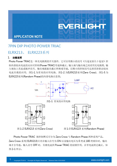
7PIN DIP PHOTO POWER TRIACELRX213、ELRX223系列1.功能说明Photo Power TRIAC是一种光电隔离的开关器件,它可以用微小的讯号(几毫安到几十毫安)控制内部较高电流的双向可控硅(Power TRIAC)导通和截止,输入端与输出端之间采用光电隔离,输入端加上直流或脉冲讯号,输出端就能从截止转换成导通。
以微小的控制讯号达到直接驱动较高电流负载的应用,图1-1.为常见的应用电路,图1-2.为ELRX213系列(Zero Cross),图1-3.为ELRX223系列(Random Phase)的内部电路示意图。
图1-1 常见的应用电路图1-2ELRX213系列(Zero Cross)图1-3ELRX223系列(Random Phase)Photo Power TRIAC 按控制模式可分为Zero Cross与Random Phase两种系列产品。
Zero Cross系列( ELRX213)只有在输入信号为ON 以及输出电压为0度或180度相位时,输出端才会导通。
输入讯号OFF时,负载电流因Power TRIAC的闭锁作用,在零电流附近截止,如图2-1所示。
Random Phase 系列( ELRX223 )则是在输入信号为ON 时,输出端马上就会导通。
输入讯号OFF 后,负载电流同样因Power TRIAC 的闭锁作用,也在零电流附近截止,如图2-2所示。
图 2-1 Zero Cross 波形时序图 图 2-2 Random phase 波形时序图2. Photo Power TRIAC 输入端特性ELRX213及ELRX223都是使用红外线发光二极管,以光传递的方式控制输出端的触发电路开关,进而控制Power TRIAC 闸极的导通或截止,较高的驱动电流可以加快导通时间,I F 与Turn on time 的关联性曲线图请参考图3.。
010********51015202530Figure 5. Turn on time vs LED currentT u r n o n t i m e , T o n (u s )LED current,I F (mA)图3. Turn on time vs LED current输入端LED 电流的大小和温度都会影响到V F 上的压降,其温度与V F 的关联性,可参考图4.。
P2LAX P2LBX P2LCX P2LDX 商品说明书
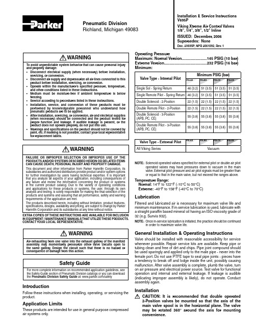
IntroductionFollow these instructions when installing, operating, or servicing the product.Application LimitsThese products are intended for use in general purpose compressed air systems only.NOTE: Solenoid operated valves specified for external pilot or double air pilotoperated valves may have pressures down to vacuum in the main valve. External pilot pressure and air pilot signals must be greater than or equal to that in the main valve, but not exceed the ranges above.Temperature Range:Normal: 14°F to 122°F (-10°C to 50°C) Extreme: -40°F to 158°F (-40°C to 70°C)LubricationFiltered and lubricated air is necessary for maximum valve life and minimum maintenance. If in-service lubrication is used, lubricate with a straight paraffin based mineral oil having an ISO viscosity grade of 32 (e.g. Sunvis 932).NOTE: Once in-service lubrication is initiated, the practice should be continuedin order to maximize valve life.General Installation & Operating InstructionsValve should be installed with reasonable accessibility for service whenever possible. Repair service kits are available. Keep pipe or tubing clean and free of dirt and chips. Pipe joint compound should be used sparingly and applied only to the male pipe - never into the female port. Do not use PTFE tape to seal pipe joints - pieces have a tendency to break off and lodge inside the unit, possibly causing malfunction. After valve assembly is complete, plumb the valve, turn on air pressure and electrical power source. Test valve for functional operation and internal and external leakage. If leakage is audible (indicating improper assembly is likely), do not operate. Conduct assembly again.InstallationCAUTION: It is recommended that double operated 2-Position valves be mounted so that the axis of the main valve spool is in the horizontal plane. The valve may be rotated 360° around the axis for mounting convenience.Pneumatic DivisionRichland, Michigan 49083Installation & Service Instructions V695PViking Xtreme Air Control Valves 1/8", 1/4", 3/8", 1/2" Inline ISSUED: December, 2006 Supersedes: NoneDoc. #V695P , NPR #061092, Rev. 1WARNINGAir exhausting from one valve into the exhaust gallery of the manifold assembly may momentarily pressurize other valve circuits open to the same gallery. Design the circuit such that there is no hazard or consequence of damage from this action.! WARNING To avoid unpredictable system behavior that can cause personal injuryand property damage:• Disconnect electrical supply (when necessary) before installation, servicing, or conversion.• Disconnect air supply and depressurize all air lines connected to this product before installation, servicing, or conversion.• Operate within the manufacturer’s specified pressure, temperature, and other conditions listed in these instructions.• Medium must be moisture-free if ambient temperature is below freezing.• Service according to procedures listed in these instructions.• Installation, service, and conversion of these products must be performed by knowledgeable personnel who understand how pneumatic products are to be applied.• After installation, servicing, or conversion, air and electrical supplies (when necessary) should be connected and the product tested for proper function and leakage. If audible leakage is present, or the product does not operate properly, do not put into use.• Warnings and specifications on the product should not be covered by paint, etc. If masking is not possible, contact your local representative for replacement labels.!WARNINGFAILURE OR IMPROPER SELECTION OR IMPROPER USE OF THEPRODUCTS AND/OR SYSTEMS DESCRIBED HEREIN OR RELATED ITEMS CAN CAUSE DEATH, PERSONAL INJURY AND PROPERTY DAMAGE.This document and other information from Parker Hannifin Corporation, its subsidiaries and authorized distributors provide product and/or system options for further investigation by users having technical expertise. It is important that you analyze all aspects of your application, including consequences of any failure and review the information concerning the product or systems in the current product catalog. Due to the variety of operating conditions and applications for these products or systems, the user, through its own analysis and testing, is solely responsible for making the final selection of the products and systems and assuring that all performance, safety and warning requirements of the application are met.The products described herein, including without limitation, product features, specifications, designs, availability and pricing, are subject to change by Parker Hannifin Corporation and its subsidiaries at any time without notice.EXTRA COPIES OF THESE INSTRUCTIONS ARE AVAILABLE FOR INCLUSION IN EQUIPMENT / MAINTENANCE MANUALS THAT UTILIZE THESE PRODUCTS. CONTACT YOUR LOCAL REPRESENTATIVE.!Safety GuideFor more complete information on recommended application guidelines, see the Safety Guide section of Pneumatic Division catalogs or you can download the Pneumatic Division Safety Guide at: /safetyOperating PressureMaximum: Normal Version........................145 PSIG (10 bar) Extreme Version.........................................232 PSIG (16 bar) Minimum:!Viking Extreme Series Air Control Valves 1/8", 1/4", 3/8", 1/2" Inline V695PPort Identification4-Way ValvesFunction Port No.Single PressureDual Pressure1 Inlet Exhaust2 Cylinder Cylinder3 Exhaust Inlet4 Cylinder Cylinder5ExhaustInletNOTE: For valves specified for dual pressure, the higher pressure is to be atport #3. 4-Way valves may be used for 3-Way function by plugging an outlet port.NOTE: For single pressure valves, the operator nearest a cylinder portcauses that cylinder port to be pressurized, when that operator is in control of the valve.Maintenance & Trouble Shooting HintsValve Not Shifting Completely When Energized:1. Check to insure that the proper voltage issupplied to the solenoids.2. Check to insure that the minimum supply pressure is equal tothat shown in the Application Limits chart above.3. Check for possible restrictions in air supply, such as undersized hoses, fittings, or quick disconnects.4. Check to insure that the spool moves smoothly.5. Check spool for proper installation, dirt, or damage.Air Leakage Through Exhaust Ports:1. Check for internal leakage in the cylinder being operated by the valve.2. Check condition of the spool for proper alignment, damaged seals and dirt contamination.3. Check for missing, damaged, or incorrectly assembled seals and gaskets.If installing new spool: Remove old spool assembly, taking care not to scratch bore. Install new spool assembly into clean bore, taking care to install squarely and push slowly to avoid damaging the spoolor the valve bore.If installing new piston: Refer to drawing for proper orientation. Installpiston/seal assembly into the operator bore, taking care to assure the lips of the seal pass smoothly into the bore.Lightly grease with provided lubricant.Inspect for nicks, scratches, and surface imperfections. If present, reduced service life is probable and future replacement should be planned.Clean with lint-free cloth.and dry thoroughly.Endcap OrientationTorque ChartP2LA M415 to 18 in.lb. (1.7 to 2.0 Nm)P2LB M310 to 12 in.lb. (1.1 to 1.4 Nm)P2LC M415 to 18 in.lb. (1.7 to 2.0 Nm)P2LD M415 to 18 in.lb. (1.7 to 2.0 Nm)A - 30mm SquareB - H - 1/2" Conduit 18" Leads R - 1/2" Conduit 72" Leads G - Grommet 18" Leads Q - Grommet72" Leads3-Position Double SolenoidService Kits Available:Service kits are available for the pilot operators and solenoids only. See the product catalog or consult local representative for kits not listed.WiringFollow all requirements for local and national electrical codes.Electrical Connection:1. Valve with lead wires should have power connected to the black wires. Ground should be connected to the green wire if provided.2. Valves with 3-Pin male terminals should have power connected to the parallel terminals. Ground should be connected to the perpendicular terminal.。
洛雷克 LAB223 系列高清1080p 无线摄像头说明书

LAB223 Series•High definition 1080p image sensor 1•IR night vision range up to130ft (40m) in ambient lighting and 90ft (28m) in total darkness 2 •Close up recognition in the dark with SmartIR •DNR (Digital Noise Reduction) for clear accurate images•ClearNight imaging for improved low light performance and improved recording efficiency •Split glass design minimizes IR reflection •83° field of view (horizontal)•Vandal resistant design with cable pass-through bracket •Versatile ceiling or wall mounting options •Residential and business friendly compact design •Weatherproof for outdoor & indoor installation (IP66 Rated) 3FEATURES:VIEW YOUR WORLD IN 1080p HDKeep an eye on your home or business day or night with High Definition 1080p quality video and long range night vision.Indoor/outdoor1080pNight Vision 130/90 FT 40/28 M83°Field of viewHIGH DEFINITION 1080p BULLET SECURITY CAMERASpecificationsImage Sensor 1/2.9” 2.1 Megapixel CMOS Video Format NTSC (LAB223) / PAL (LAB223P) Effective Pixels1920 × 1080Resolution 1080p Scan System P rogressive Sync System Internal Iris AES AES Shutter Speed 1/30 ~ 1/50,000 Sec.Min. Illumination0.2 Lux without IR LED / 0 Lux with IR LED 2Video Output A-M P X Lens / Lens Type3.6mm F2.0 / FixedField of View (Horizontal) 83°Termination BNC Type IR LED Type 18 pieces /850nm Night Vision Range 130ft (40m) / 90ft (28m) 2Power Requirement 12V DC ±10%Power Consumption Max. 310mA (with IR)Operating Temp. Range -22° ~ 140°F / -30° ~ 60°C Operating Humidity Range< 90% RHEnvironmental Rating I P 663Dimensions (W × D × H) 2.7” × 6.2” × 2.7” 50 × 158 × 50mm Weight0.45lbs / 0.2kg1. 1080p HD cameras are compatible with select Lorex HD DVR recorders. For a full list of compatible recorders, visit /compatibility2. Stated IR illumination range is based on ideal conditions in typical outdoor night time ambient lighting and in total darkness. Actual range and image clarity depends on installation location, viewing area, and light reflection / absorption level of object. In low light, the camera will switch to black and white.3. Not intended for submersion in water. Installation in a sheltered location recommended.Product InformationLAB223B 6-95529-01221-6LAB223SB 6-95529-01464-7Configuration 1080p HD Security Camera Package Brown Box Package Weight: 1.7lb / 0.77kg Package Dimensions:(W x D x H)9.05 × 4.84 × 5.7”230 × 123 × 145mm Package Cube:0.14cft / 0.003cbmContents:1 × 1080p HD Bullet Camera, 1 x 60ft/18m BNC/DC extension cable, 1 x Mounting Kit, 1 x US Power Adapter, Quick Setup Guide DisclaimersConnecting the Cameras Setup DiagramCameraHD DVRLAB223S 6-95529-01869-0LAB223P 6-95529-01081-6Configuration 1080p HD Security Camera Package Retail Giftbox Package Weight: 1.7lb / 0.77kg Package Dimensions:(W x D x H)9.05 × 4.84 × 5.7”230 × 123 × 145mm Package Cube:0.14cft / 0.003cbmContents:1 × 1080p HD Bullet Camera, 1 x 60ft/18m BNC/DC extension cable, 1 x Mounting Kit, 1 x UK/EU/US Power Adapter, Quick Setup Guide© 2018 Lorex TechnologyAs our product is subject to continuous improvement, Lorex T echnology & subsidiariesreserve the right to modify product design, specifications & prices without notice and withoutincurring any obligation. E&OE. 3-06052018 (18-0840-LOR)Lorex Technology250 Royal Crest Court Markham, Ontario,Canada L3R 3S1。