Molex 505070-4020 Molex505070系列规格书
MOLEX汽车连接器产品大全-4
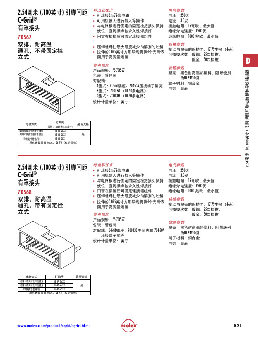
71349-X055
71349-X089
71349-X022
71349-X056
71349-X090
71349-X023
71349-X057
71349-X091
71349-X024
71349-X058
71349-X092
71349-X025
71349-X059
71349-X093
71349-X026
/product/cgrid/cgrid.html
D-31
2.54 (.100英寸) 引脚间距 C-Grid® 有罩接头
71349 双排,表面贴装 立式,配有或未配有固定栓
D
特点和优点 • 全防护塑壳,可在插拔时保护引脚 • 极化防误插槽在连接器插接时可引导导
向轨,以防止引脚被碰坏。 • 闩窗在插接后提供强制锁定 • 推压式固定栓在焊脚焊接时提供对印刷
参考信息 产品规格:PS-75100-001 包装:托盘包装 UL档案编号:E29179 CSA档案编号:LR19980 对配端:71973,带凸缘 设计计量单位:英寸
镀金:50次插拔
物理参数 塑壳:黑色耐高温热塑料,阻燃级别
为UL 94V-0级 端子材料:铜合金 电镀:见表
电镀方式
订购号
是否无铅
最薄15微英寸选择性镀金
15-47-76XX
最薄30微英寸选择性镀金
15-47-77XX
是
150微英寸镀锡/铅
15-47-75XX
用电路数量替换XX。 06-72 (仅为偶数)
镀金:50次插拔
D
设计计量单位:英寸
物理参数 塑壳:黑色聚酯,阻燃级别为UL 94V-0级
端子材料:铜合金
5050参数
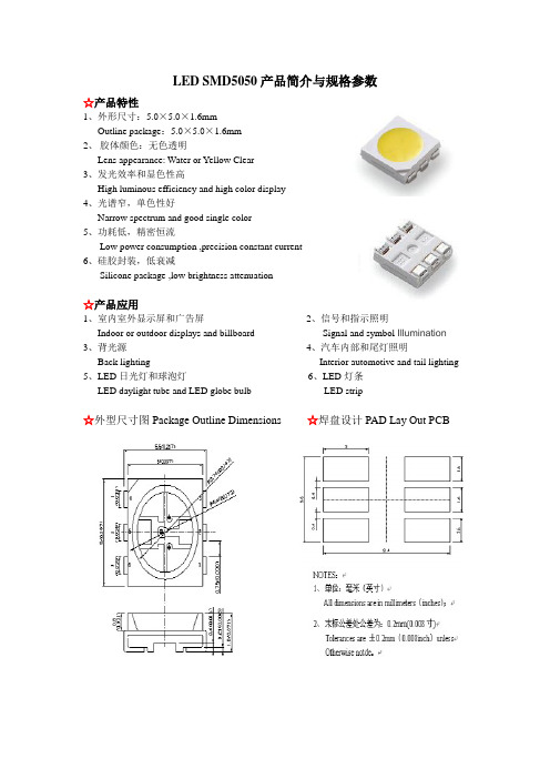
LED SMD5050产品简介与规格参数☆产品特性1、外形尺寸:5.0×5.0×1.6mmOutline package:5.0×5.0×1.6mm2、胶体颜色:无色透明Lens appearance: Water or Yellow Clear3、发光效率和显色性高High luminous efficiency and high color display4、光谱窄,单色性好Narrow spectrum and good single color5、功耗低,精密恒流Low power consumption ,precision constant current6、硅胶封装,低衰减Silicone package ,low brightness attenuation☆产品应用1、室内室外显示屏和广告屏2、信号和指示照明Indoor or outdoor displays and billboard Signal and symbol Illumination 3、背光源4、汽车内部和尾灯照明Back lighting Interior automotive and tail lighting 5、LED日光灯和球泡灯6、LED灯条LED daylight tube and LED globe bulb LED strip☆外型尺寸图Package Outline Dimensions☆焊盘设计PAD Lay Out PCBLED SMD5050 0.2W正白最大绝对额定值Absolute maximum ratings at Ta=25度参数 Parameter 符号Symbol 值Value 单位Unit 功率耗损Power dissipation Pd 200 mW正向电流Forward current If 70 mA反向电压Reverse voltage Vr 5 V 工作温度范围Operating temperature range Topr ﹣40-﹢80 ℃贮存温度范围Storage temperature range Tstg ﹣40-﹢85 ℃最大脉冲电流Peak pulsing current Ifp 100 mA 抗静电能力Electrostatic Discharge ESD 4000 VLED SMD5050 0.2W正白光电特性Electrical optical characteristics at Ta=25度参数Parameter符号Symbol值Value单位Unit测试条件Test Conditions Min Typ Max正向电压Forward voltage VF 3.0 / 3.6 V IF=60 mA 发光强度Luminous intensity IV 3000 4500 Mcd IF=60 mA 角度Viewing angles2θ1/2 120 Dge IF=60 mA 色温Color temperature TC 5500 6500 K IF=60 mA 光通量Luminous flux/ 10 12 Lm IF=60 mA 反向电流Reverse current IR 10 μA VR=5VLED SMD5050 0.2W其他产品光电参数发光颜色Emitting Color 产品型号Model正向电压ForwardVoltage(v)正向电流ForwardCurrent(mA)色温或波段CCT(k) orWD(nm)发光强度LuminousIntensity(Mcd)角度Beanangel(°)蓝色(Blue)SY-5050-BE02 3.0—3.660 460-465600-1800 120 绿色(Green)SY-5050-GN02 3.0—3.660 520-5251800-3000 120 红色(Red )SY-5050-RD02 1.8—2.4 60 620-625800-1500 120 黄色(Yellow)SY-5050-YW02 1.8—2.4 60 585-590600-1500 120RGB SY-5050-RGB021.8—2.4 60 620-625(R)300-500 120 3.0—3.6 60 520-525(G)600-1200 120 3.0—3.6 60 460-465(B)250-600 120温馨提示:所有参数均为实验得出的统计参数,因测试设备、具体使用芯片不同,具体参数以单个产品实验数据为准。
产品规格书word版

产品规格书目录目录 (1)1. 适用范围 (2)2. 产品说明 (2)3. 产品参数 (3)4. 信号引脚定义 (4)5. 规格型号说明 (4)6. IC贴片图 (4)7. 安装孔位图 (5)8. 室内P6.0八扫全彩表贴三拼一单元板备件 (7)9. 产品使用注意事项 (7)1. 适用范围本技术手册仅适用于室内P6.0(32*16)八扫全彩表贴三拼一单元板。
2. 产品说明2.1. 室内P6.0八扫全彩表贴三拼一单元板主要是由红色LED、绿色LED和蓝色LED组成矩阵,然后再固定到塑胶套件上而成;2.2. 此单元板含有驱动芯片和输入缓冲芯片,连接到LED显示屏控制系统即可显示视频、图像和文字信息等;2.3. 通过PWM信号驱动红色LED、绿色LED和蓝色LED的驱动芯片,可形成16,777,216种颜色变换;2.4. 此单元板可以按水平和垂直方向任意拼接,从而拼成不同大小的显示屏;2.5. 单元板的特点:●用超高亮的LED和优质的塑胶件●高对比度可达到良好的显示效果●重量轻易于安装、拆卸●可进行单点、单灯维护,成本低●采用恒流方式驱动LED,发光均匀,功耗低●像素间距为6.0mm,共有32*16个像素点,每个像素点由1R1G1B组成2.6. 单元板图片正视图背视图3. 产品参数(温度条件:Ta=25℃)4. 信号引脚定义HUB755. 规格型号说明产品型号命名规范:6. IC 贴片图5 R2 红色数据信号6 G2 绿色数据信号7 B2 蓝色数据信号8 GND 电源地9 A 行电源控制信号 10 B 行电源控制信号 11 C 行电源控制信号 12 GND 电源地 13 CLK 时钟信号 14 LAT 数据锁存信号 15OE使能信号16GND电源地元器件 贴片位置 元器件 贴片位置 74HC245 U1-U274H138 U3 16126DUR1-UR4、UG1-UG4、UB1- UB4 4953 T1-T8 电阻391,390ΩRR1-RR4、RG1-RG4、RB1-RB4电容104C1-C15排阻560,56Ω RP1-RP8、RP13-RP20 (空白)备注:VRR 、VRG 、VRB 为白平衡调节电阻,其阻值根据使用不同灯管的实际情况而定。
5050RGB规格书(中文)
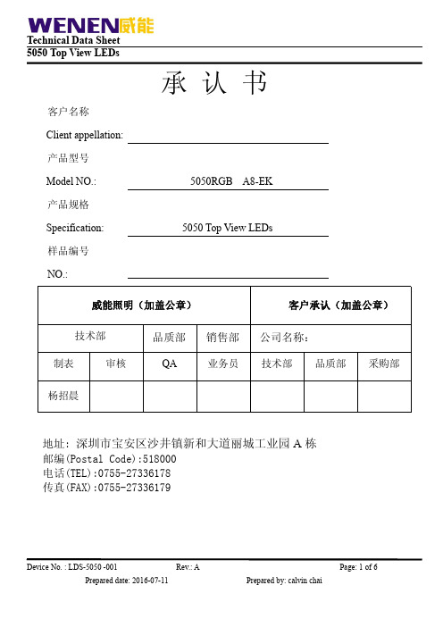
标示区有无由蓝色变为粉红色.如漏气或变色现象,请联系厂家或退回厂家高温除湿处理,(高温除湿 环境:120 度,6H)切勿自行处理 2-2. 打开包装前, LEDs 需储存在温度低于 30℃,湿度低于 70%RH 。 2-3. 打开包装后,在温度低于 30℃ ,湿度低于 60%RH 的情况下,且开封到焊接完成控制在 4H。 2-4. 如果吸湿材料 (硅凝胶)已经消退或是 LEDs 已经超过了储存时间, 则需要基于以下条件进行烘烤 处理: 60±5℃ / 24 小时。 3. 回流焊注意事项 3-1. 无铅锡膏的温度曲线
█ 电性与光学特性(Ta=25℃)
参数 正向电压 反向电流 发光角度 波长
光通量
符号
条件
最小 平均 最大 单位
R IF=20mA
2.0
--
2.3
VF G IF=20mA
2.9
--
3.2
V
B IF=20mA
2.9
--
3.2
IR
VR=5V
--
--
5
μA
2θ1/2
IF=3*20mA
--
120
--
deg
R IF=20mA
3-2. 回流焊不能超过两次。 3-3. 焊接期间, 加热时不要在 LEDs 上添加任何压力。 3-4. 焊接后, 正常回温至 40℃以下后才可过电流。 4. 防护措施
用适当的工具从材料侧面夹取,因产品使用硅胶封装避免在应用过程中压伤胶体,损伤内部结构造
成不良。LED 为半导体敏感器件,静电放电(ESD)或脉冲电流(EOS)可能会损害 LED。 作业机台 有效接地、作业中作好静电防护,可有效提升产品品质。贴片 LED 灯珠在生产过程中及灯具使用环境 需避免与硫.卤素.酸.醇.碱.酮肟类挥发性化合物,强氧化物.增塑剂(又名塑化剂,领苯二甲酸二辛酯 DOP 或邻苯二甲酸二丁酯 DBP,PVC 物料即含有大量增塑剂)等腐蚀性物质接触
Molex电子技术(LLC)产品说明书:76145型号的连接器组装

GENERALTOLERANCES(UNLESS SPECIFIED)ANGULAR TOL ±0.5°4 PLACES ±3 PLACES ±THIS DRAWING CONTAINS INFORMATION THAT IS PROPRIETARY TO MOLEX ELECTRONIC TECHNOLOGIES, LLC AND SHOULD NOT BE USED WITHOUT WRITTEN PERMISSIONDIMENSION UNITS SCALE MM 4:1DRWN BYDATEMSANDBERG2007/12/26CHK'D BYDATEIMPACT 6 PAIR HEADERRIGHT GUIDED ASSEMBLY SALES DRAWINGE D T O N X2017/10/302017/10/312017/11/02ZZSECTION Z -Z8.502.9528.922.9513.210.95(ADD FOR END WALL)1.35B 4.751.9017X1.35SIGNAL HOLESREFGROUND HOLESREFROW L ROW K ROW J ROW D ROW C ROW O ROW B ROW H ROW G ROW F ROW E ROW S ROW N ROW P ROW R ROW M ROW A ROW TKEEP OUT ZONESEE PART NUMBER CHARTANDPART NUMBER LOGIC (18 HOLES PER COLUMN)SEE NOTE #7UNPLATED SCREW HOLE3.56±0.08⌀⌖⌀0.10⌖⌀0.15PIN A11.901.4TAIL LENGTHMINIMUM BOARD1.002.64KEY SHOWN IN POSITION 'A'28.9+0.2-0.5B17X1.35P ±0.2022.9511.9528.620.4(PIN LENGTH)NOTCH DESIGNATESROW AA NOTES:1. MATERIALS: HOUSING - LIQUID CRYSTAL POLYMER (LCP)GLASS-FILLED, UL94V-0TERMINALS - HIGH PERFORMANCE COPPER ALLOY 2. FINISH: 30µ MIN GOLD IN CONTACT AREA. SELECTIVE TIN ON PCB TAILS. NICKEL OVERALL.3. REFER TO MOLEX PRODUCT SPECIFICATION PS-76060-999FOR PERFORMANCE SPECIFICATIONS AND ADDITIONAL PCB INFORMATION. 4. THIS PART CONFORMS TO CLASS B REQUIREMENTS OF MOLEX COSMETIC SPEC PS-45499-002. 5. PACKAGE PER: PK-70873-760.6. SEE SHEETS 2 & 3 FOR PART NUMBERS AND BOARD RELATIONSHIPS.7. FOR GROUNDED GUIDE PINS USE DIA. 3.56 +/-0.08 (PTH) DIA. 3.66 (DRILL) AND DIA 6.5 (PAD).8. MATES WITH IMPACT DC SERIES NO. 76150.9. KEEP OUT ZONE FOR BP HOUSING LENGTH INCLUDES AN ADDITIONAL 1.0MM TO ACCOMMODATE FOR SPACE REQUIRED BY DC FRONT HOUSING.10. REFER TO MOLEX PCB ROUTING GUIDE AS-76060-990 FOR ANTIPAD AND ROUTING RECOMMENDATIONS. 11. CONNECTORS SUPPLIED WITH A 2-56 UNC-2A SCREW.RIGHT GUIDEDBACKPLANE HOLE PATTERN(CONNECTOR SIDE)SEE NOTE 12BBC CDDEEFFGGHHJJKKLLGENERALTOLERANCES(UNLESS SPECIFIED)ANGULAR TOL ±0.5°4 PLACES ±3 PLACES ±THIS DRAWING CONTAINS INFORMATION THAT IS PROPRIETARY TO MOLEX ELECTRONIC TECHNOLOGIES, LLC AND SHOULD NOT BE USED WITHOUT WRITTEN PERMISSIONDIMENSION UNITS SCALE MM 4:1DRWN BY DATEMSANDBERG2007/12/26CHK'D BYDATEIMPACT 6 PAIR HEADERRIGHT GUIDED ASSEMBLY SALES DRAWINGE D T O N X2017/10/302017/10/312017/11/02MATERIAL NUMBER # OF COLUMNS # OF DIFF PAIR DIM 'A'DIM 'B'GUIDE RIGHT OPEN WALL OPTION76145-*1**106025.517.1076145-*7**148433.124.7076145-*6**169636.928.50MATERIAL NUMBER# OF COLUMNS # OF DIFF PAIR DIM 'A'DIM 'B'GUIDE RIGHT END WALL OPTION76145-*1**106026.917.1076145-*7**148434.524.7076145-*6**169638.328.50GUIDE RIGHT OPEN WALL OPTIONGUIDE RIGHT END WALL OPTION76145 -****PIN LENGTH (P)KEY ORIENTATION 0 = NO KEY 1 = A 2 = B 3 = C 4 = D 5 = E 6 = F 7 = G 8 = H# OF COLUMNS 1 = 10 COL 6 = 16 COL 7 = 14 COLMODULE TYPE5 = GUIDE RIGHT, TIN9 = GUIDE RIGHT END WALL, TIN3 = 4.50 (SHORT COMPLIANT, 0.46±0.05 PTH)4 = 4.90 (SHORT COMPLIANT, 0.46±0.05 PTH)5 = 5.50 (SHORT COMPLIANT, 0.46±0.05 PTH)6 = 4.50 (MICRO COMPLIANT, 0.39±0.05 PTH)7 = 4.90 (MICRO COMPLIANT, 0.39±0.05 PTH)8 = 5.50 (MICRO COMPLIANT, 0.39±0.05 PTH)PART NUMBER LOGICPART NUMBER TABLEBBC CDDE EF FG GHHJ JKKLLGENERALTOLERANCES(UNLESS SPECIFIED)ANGULAR TOL ±0.5°4 PLACES ±3 PLACES ±THIS DRAWING CONTAINS INFORMATION THAT IS PROPRIETARY TO MOLEX ELECTRONIC TECHNOLOGIES, LLC AND SHOULD NOT BE USED WITHOUT WRITTEN PERMISSIONDIMENSION UNITS SCALE MM 4:1DRWN BYDATEMSANDBERG2007/12/26CHK'D BYDATEIMPACT 6 PAIR HEADERRIGHT GUIDED ASSEMBLY SALES DRAWINGE D T O N X2017/10/302017/10/312017/11/02IMPACT 6 PAIRBOARD RELATIONSHIPSBP ROW ADCARD PCBBPLANE PCBBP HOLE COLUMN (COLUMN 10 REF)DC HOLE COLUMN (COLUMN 10 REF)DCARD ROW ABPLANE PCBDCARD PCBDCARD ROW AB P R O W A0.35OFFSET BETWEEN DC ANDBP HOLE COLUMNS28.93.011.9514.0BBC CDDE EF FGGH HJ JKKLL。
MPXV5050G中文资料

MPX5050Rev 9, 05/2007Freescale Semiconductor Technical Data© Freescale Semiconductor, Inc., 2007. All rights reserved.Integrated Silicon Pressure Sensor On-Chip Signal Conditioned, Temperature Compensated and CalibratedThe MPX5050/MPXV5050G series piezoresistive transducer is a state-of-the-art monolithic silicon pressure sensor designed for a wide range of applications, but particularly those employing a microcontroller or microprocessor with A/D inputs. This patented, single element transducer combines advancedmicromachining techniques, thin-film metallization, and bipolar processing to provide an accurate, high level analog output signal that is proportional to the applied pressure.Features • 2.5% Maximum Error over 0° to 85°C•Ideally suited for Microprocessor or Microcontroller-Based Systems •Temperature Compensated Over –40° to +125°C •Patented Silicon Shear Stress Strain Gauge •Durable Epoxy Unibody Element •Easy-to-Use Chip Carrier OptionORDERING INFORMATIONDevice Type OptionsCase No.MPX Series Order No.Packing Options Device Marking SMALL OUTLINE PACKAGE (MPXV5050G SERIES)Ported ElementSide Port 1369MPXV5050GP Trays MPXV5050G Dual Port 1351MPXV5050DP Trays MPXV5050G Axial Port482A MPXV5050GC6U TraysMPXV5050G482A MPXV5050GC6T1Tape & Reel MPXV5050GUNIBODY PACKAGE (MPX5050 SERIES)BasicElement Differential 867MPX5050D—MPX5050D Ported ElementDifferential Dual Ports 867C MPX5050DP —MPX5050DP Gauge867B MPX5050GP—MPX5050GPMPX5050 MPXV5050G SERIESINTEGRATED PRESSURE SENSOR 0 to 50 kPa (0 to 7.25 psi)0.2 to 4.7 V OutputSMALL OUTLINE PACKAGEPIN NUMBERS (1)1.Pins 1, 5, 6, 7, and 8 are internal device connections. Do not connect to external circuitry or ground. Pin 1 is noted by the notch in the lead.1N/C 5N/C 2V S 6N/C 3Gnd 7N/C 4V out8N/CUNIBODY PACKAGE PIN NUMBERS (1)1.Pins 4, 5, and 6 are internal deviceconnections. Do not connect to external circuitry or ground. Pin 1 is noted by the notch in the lead.1V out 4N/C 2Gnd 5N/C 3V S6N/CMPX5050SensorsFigure 1. Fully Integrated Pressure Sensor SchematicTable 1. Maximum Ratings (1)1.Exposure beyond the specified limits may cause permanent damage or degradation to the device.RatingSymbol Value Unit Maximum Pressure (P1 > P2)P max 200kPa Storage Temperature T stg –40° to +125°°C Operating TemperatureT A–40° to +125°°CSensing ElementThin Film Temperature Compensationand Gain Stage #1Gain Stage #2and Ground Reference Shift CircuitryV SV outGNDPins 4, 5, and 6 are NO CONNECTS for Unibody DevicePins 1, 5, 6, 7, and 8 are NO CONNECTS for Small Outline Package DeviceMPX5050SensorsTable 2. . Operating Characteristics (V S = 5.0 Vdc, T A = 25°C unless otherwise noted, P1 > P2. Decoupling circuit shown in Figure 4 required to meet electrical specifications.)CharacteristicSymbol Min Typ Max Unit Pressure Range (1)1. 1.0 kPa (kiloPascal) equals 0.145 psi.P OP 0—50kPa Supply Voltage (2)2.Device is ratiometric within this specified excitation range.V S 4.75 5.0 5.25Vdc Supply CurrentI o —7.010mAdc Minimum Pressure Offset (3)(0 to 85°C)@ V S = 5.0 Volts 3.Offset (V off ) is defined as the output voltage at the minimum rated pressure.V off0.0880.20.313VdcFull Scale Output (4)(0 to 85°C)@ V S = 5.0 Volts 4.Full Scale Output (V FSO ) is defined as the output voltage at the maximum or full rated pressure.V FSO4.587 4.7 4.813VdcFull Scale Span (5)(0 to 85°C)@ V S = 5.0 Volts 5.Full Scale Span (V FSS ) is defined as the algebraic difference between the output voltage at full rated pressure and the output voltage at the minimum rated pressure.V FSS— 4.5—VdcAccuracy (6)(0 to 85°C)6.Accuracy (error budget) consists of the following:•Linearity:Output deviation from a straight line relationship with pressure over the specified pressure range.•Temperature Hysteresis:Output deviation at any temperature within the operating temperature range, after the temperature is cycled toand from the minimum or maximum operating temperature points, with zero differential pressure applied.•Pressure Hysteresis:Output deviation at any pressure within the specified range, when this pressure is cycled to and from theminimum or maximum rated pressure at 25°C.•TcSpan:Output deviation over the temperature range of 0° to 85°C, relative to 25°C.•TcOffset:Output deviation with minimum pressure applied, over the temperature range of 0° to 85°C, relative to 25°C.•Variation from Nominal:T he variation from nominal values, for Offset or Full Scale Span, as a percent of V FSS at 25°C.———±2.5%V FSS Sensitivity V/P —90—-mV/kPa Response Time (7)7.Response Time is defined as the time for the incremental change in the output to go from 10% to 90% of its final value when subjected to a specified step change in pressure.t R — 1.0—-ms Output Source Current at Full Scale Output I o+—0.1—-mAdc Warm-Up Time (8)8.Warm-up Time is defined as the time required for the product to meet the specified output voltage after the Pressure has been stabilized.——20—-ms Offset Stability (9)9.Offset Stability is the product's output deviation when subjected to 1000 hours of Pulsed Pressure, Temperature Cycling with Bias Test.——±0.5—-%V FSSMPX5050SensorsFigure 3 illustrates the Differential/Gauge Sensing Chip in the basic chip carrier (Case 867). A fluorosilicone gel isolates the die surface and wire bonds from the environment, while allowing the pressure signal to be transmitted to the sensor diaphragm.The MPX5050/MPXV5050G series pressure sensor operating characteristics, and internal reliability andqualification tests are based on use of dry air as the pressure media. Media, other than dry air, may have adverse effects on sensor performance and long-term reliability. Contact the factory for information regarding media compatibility in your application.Figure 2 shows the sensor output signal relative to pressure input. Typical, minimum, and maximum output curves are shown for operation over a temperature range of 0× to 85×C using the decoupling circuit shown in Figure 4. The output will saturate outside of the specified pressure range.Figure 4 shows the recommended decoupling circuit for interfacing the output of the integrated sensor to the A/D input of a microprocessor or microcontroller. Proper decoupling of the power supply is recommended.Figure 2. Output versus Pressure DifferentialFigure 3. Cross-Sectional Diagram(not to scale)Figure 4. Recommended Power Supply Decouplingand Output Filtering(For additional output filtering, please refer toApplication Note AN1646.)Table 3. Mechanical CharacteristicsCharacteristicsTyp Unit Weight, Basic Element (Case 867) 1.8grams Weight, Basic Element (Case 1369) 3.376grams Weight, Basic Element (Case 482A)gramsDifferential Pressure (kPa)O u t p u t (V )5.04.54.03.53.02.52.01.51.00.500510152025303540455550Transfer Function:V out = V S *(0.018*P+0.04) ± ERROR V S = 5.0 VdcTEMP = 0 to 85°C TYPICALMINMAX+5 V1.0 μF0.01 μF470 pFGNDV sV outIPSOUTPUTFluoro Silicone Gel Die CoatWire BondDieP1Stainless Steel Metal CoverLead FrameDie BondEpoxy Plastic CaseP2Differential/Gauge ElementMPX5050SensorsPRESSURE (P1)/VACUUM (P2) SIDE IDENTIFICATION TABLEFreescale designates the two sides of the pressure sensor as the Pressure (P1) side and the Vacuum (P2) side. The Pressure (P1) side is the side containing fluorosilicone gel which protects the die from harsh media. The MPX pressuresensor is designed to operate with positive differential pressure applied, P1 > P2.The Pressure (P1) side may be identified by using the table below:Nominal Transfer Value:V out = V S (P x 0.018 + 0.04)± (Pressure Error x Temp. Factor x 0.018 x V S )V S = 5.0 V ± 0.25 VdcTransfer FunctionMPX5050/MPXV5050G SERIESTemp Multiplier –403 0 to 851 +1253Temperature in °C4.03.02.00.01.0–40–2020406014012010080Temperature Error FactorNOTE: The Temperature Multiplier is a linear response from 0° to –40°C and from 85° to 125°C.Temperature Error BandPressure Error (Max)Pressure Error Band0 to 50 (kPa)±1.25 (kPa)Error Limits for PressurePressure (in kPa)3.02.01.0–1.0–2.0–3.00.0102030405060P r e s s u r e E r r o r (k P a )Part NumberCase TypePressure (P1) Side IdentifierMPX5050D 867Stainless Steel Cap MPX5050DP 867C Side with Part Marking MPX5050GP 867B Side with Port Attached MPXV5050GP 1369Side with Port Attached MPXV5050DP 1351Side with Part Marking MPXV5050GC6U/T1482AVertical Port AttachedPACKAGE DIMENSIONSCASE 867-08ISSUE NUNIBODY PACKAGECASE 867C-05ISSUE FUNIBODY PACKAGEMPX5050SensorsPACKAGE DIMENSIONSMPX5050 SensorsPACKAGE DIMENSIONSMPX5050SensorsPACKAGE DIMENSIONSMPX5050 SensorsPACKAGE DIMENSIONSMPX5050SensorsPACKAGE DIMENSIONSMPX5050 SensorsPACKAGE DIMENSIONSMPX5050SensorsCASE 482A-01ISSUE ASMALL OUTLINE PACKAGEMPX5050 SensorsMPX5050 Rev 9How to Reach Us:Home Page:Web Support:/supportUSA/Europe or Locations Not Listed: Freescale Semiconductor, Inc. Technical Information Center, EL516 2100 East Elliot RoadTempe, Arizona 85284+1-800-521-6274 or +1-480-768-2130 /supportEurope, Middle East, and Africa:Freescale Halbleiter Deutschland GmbHTechnical Information CenterSchatzbogen 781829 Muenchen, Germany+44 1296 380 456 (English)+46 8 52200080 (English)+49 89 92103 559 (German)+33 1 69 35 48 48 (French)/supportJapan:Freescale Semiconductor Japan Ltd.HeadquartersARCO Tower 15F1-8-1, Shimo-Meguro, Meguro-ku,Tokyo 153-0064Japan0120 191014 or +81 3 5437 9125support.japan@Asia/Pacific:Freescale Semiconductor Hong Kong Ltd.Technical Information Center2 Dai King StreetTai Po Industrial EstateTai Po, N.T., Hong Kong+800 2666 8080@For Literature Requests Only:Freescale Semiconductor Literature Distribution Center P.O. Box 5405Denver, Colorado 802171-800-441-2447 or 303-675-2140Fax: 303-675-2150 LDCForFreescaleSemiconductor@ Information in this document is provided solely to enable system and software implementers to use Freescale Semiconductor products. There are no express or implied copyright licenses granted hereunder to design or fabricate any integrated circuits or integrated circuits based on the information in this document.Freescale Semiconductor reserves the right to make changes without further notice to any products herein. Freescale Semiconductor makes no warranty, representation or guarantee regarding the suitability of its products for any particular purpose, nor does Freescale Semiconductor assume any liability arising out of the application or use of any product or circuit, and specifically disclaims any and all liability, including without limitation consequential or incidental damages. “Typical” parameters that may be provided in Freescale Semiconductor data sheets and/or specifications can and do vary in different applications and actual performance may vary over time. All operating parameters, including “Typicals”, must be validated for each customer application by customer’s technical experts. Freescale Semiconductor does not convey any license under its patent rights nor the rights of others. Freescale Semiconductor products are not designed, intended, or authorized for use as components in systems intended for surgical implant into the body, or other applications intended to support or sustain life, or for any other application in which the failure of the Freescale Semiconductor product could create a situation where personal injury or death may occur. Should Buyer purchase or use Freescale Semiconductor products for any such unintended or unauthorized application, Buyer shall indemnify and hold Freescale Semiconductor and its officers, employees, subsidiaries, affiliates, and distributors harmless against all claims, costs, damages, and expenses, and reasonable attorney fees arising out of, directly or indirectly, any claim of personal injury or death associated with such unintended or unauthorized use, even if such claim alleges that Freescale Semiconductor was negligent regarding the design or manufacture of the part. Freescale™ and the Freescale logo are trademarks of Freescale Semiconductor, Inc. All other product or service names are the property of their respective owners.© Freescale Semiconductor, Inc. 2007. All rights reserved.。
Field Xpert SMT70 平板电脑配置应用商品介绍说明书
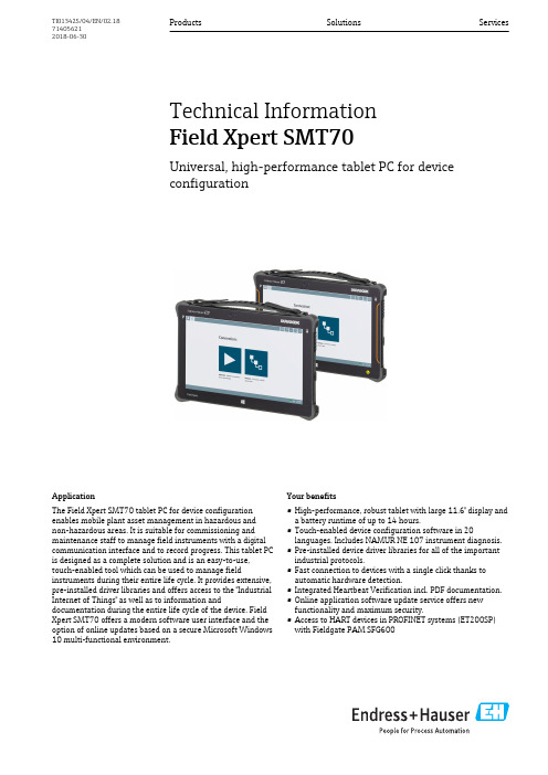
ApplicationThe Field Xpert SMT70 tablet PC for device configuration enables mobile plant asset management in hazardous and non-hazardous areas. It is suitable for commissioning and maintenance staff to manage field instruments with a digital communication interface and to record progress. This tablet PC is designed as a complete solution and is an easy-to-use,touch-enabled tool which can be used to manage fieldinstruments during their entire life cycle. It provides extensive,pre-installed driver libraries and offers access to the "Industrial Internet of Things" as well as to information anddocumentation during the entire life cycle of the device. Field Xpert SMT70 offers a modern software user interface and the option of online updates based on a secure Microsoft Windows 10 multi-functional environment.Your benefits•High-performance, robust tablet with large 11.6" display and a battery runtime of up to 14 hours.•Touch-enabled device configuration software in 20languages. Includes NAMUR NE 107 instrument diagnosis.•Pre-installed device driver libraries for all of the important industrial protocols.•Fast connection to devices with a single click thanks to automatic hardware detection.•Integrated Heartbeat Verification incl. PDF documentation.•Online application software update service offers new functionality and maximum security.•Access to HART devices in PROFINET systems (ET200SP)with Fieldgate PAM SFG600Products Solutions ServicesTechnical Information Field Xpert SMT70Universal, high-performance tablet PC for device configurationTI01342S/04/EN/02.18714056212018-06-30Field Xpert SMT702Endress+HauserTable of contentsAbout this document ........................3Symbols used (3)Function and system design (4)Function ...................................4System design ................................4Communication and data processing .. (8)Power supply ..............................8Supply voltage ...............................8Battery ....................................8Performance characteristics (9)Hardware ..................................9Software ...................................9Environment (10)Ambient temperature range .....................10Storage temperature ..........................10Humidity ..................................10Operating height .............................10Degree of protection ..........................11Shock resistance .............................11Vibration resistance ...........................11Electromagnetic compatibility ....................11Mechanical construction (12)Design, dimensions ...........................12Weight ...................................12Materials . (12)Software operation .........................12Certificates and approvals ...................12CE approval ................................12Radio approval ..............................12Ex approval .. (12)Ordering Information (13)Scope of delivery (13)Accessories ...............................13Documentation . (13)Field Xpert SMT70............................13Fieldgate PAM SFG600 (13)Registered trademarks (13)Field Xpert SMT70About this documentSymbols used Safety symbolsSymbols for certain types of informationEndress+Hauser3Field Xpert SMT704Endress+HauserFunction and system designFunctionThe Field Xpert SMT70 tablet PC for universal device configuration supports protocols such as HART,PROFIBUS DP/PA, FOUNDATION Fieldbus, Modbus, and Endress+Hauser service protocols (CDI, ISS,IPC and PCP). The devices can be connected directly via a suitable interfacee.g. a modem (point-to-point) or a bus system (point-to-bus). The Field Xpert software package is fast, easy and intuitive to use. The Field Xpert device library has more than 2,700 pre-installed device and communication drivers. They can be used to operate practically all HART andFOUNDATION Fieldbus devices (FieldComm Group libraries). Furthermore all Endress+Hauser field device drivers are installed. Further device drivers (DTMs) can be installed additionally. The generic HART DTM and PROFIBUS profile DTMs also enable operation of all the important basic functionality of the relevant field devices.System design1Network architectureThe following modems/interfaces are supported by the Field Xpert SMT70 tablet PC:•HART–Commubox FXA195 (4 to 20 mA)–MACTek Bluetooth modem (4 to 20 mA)–Memograph RSG45 (4 to 20 mA)–MACTek USB modem (4 to 20 mA)•HART via PROFINET together with Fieldgate PAM SFG600•PROFIBUS–Softing PROFIusb –Softing PBpro USB –Fieldgate SFG500•FOUNDATION Fieldbus –NI USB–Softing FFusb •ModbusModbus serial •WirelessHARTWireless HART adapter SWA70•Endress+Hauser service interfaces –Commubox FXA291–Commubox FXA193–TXU10 V2–TXU10 V1–CDI USB –CDI TCP/IPField Xpert SMT70Endress+Hauser 5HART point-to-point connection via Commubox FXA195This diagram shows a HART point-to-point connection with an FXA195 USB/HART modem. If an FXA195 is connected to the computer, the Field Xpert SMT70 tablet PC can connect to the device automatically.2Point-to-point connection with a HART field device 1Field Xpert SMT70 tablet PC 2HART Commubox FXA1953Field deviceTo establish communication with the HART device, a resistor of at least 250 Ω must be provided in the circuit. The way in which this is done depends upon the system architecture and power source used. Please read the FXA195 manual carefully.HART point-to-point connection via MACTek Bluetooth modem3Point-to-point connection via a load resistor 1Load resistor: 250 to 1 100 Ω2HART device3Field Xpert SMT70 tablet PC 4VIATOR Bluetooth modem 5Transmitter power supply unitCDI point-to-point connectionThis diagram shows a CDI point-to-point connection with a Commubox FXA291 interface. If this Commubox is connected to the computer, the Field Xpert SMT70 tablet PC can connect to the device automatically.Field Xpert SMT704CDI point-to-point connection with a field device1Field Xpert SMT70 tablet PC2Commubox FXA291 CDI3Field device with CDI interface6Endress+HauserField Xpert SMT70Endress+Hauser 7HART via PROFINET5Network architecture1Field Xpert SMT70 tablet PC 2Switch3Wireless router4PROFINET controller5PROFINET segment ETH16PROFINET switch7Siemens ET200SP IM 155-6PN HF 8Fieldgate PAM SFG6009Plant network PAM Client ETH210Firewall11Office networkPROFIBUS point-to-bus connectionThis diagram shows how the connection from PROFIBUS DP to PROFIBUS PA can be established using a Siemens DP/PA Link or a Pepperl+Fuchs SK3.Field Xpert SMT708Endress+Hauser6PROFIBUS point-to-bus connection via Fieldgate SFG5001Field Xpert SMT70 tablet PC 2Ethernet3Fieldgate SFG5004PROFIBUS DP 5Segment coupler 6PROFIBUS PACommunication and data processingUSB2 x USB 3.0Wireless LAN Intel Wireless AC7260 802.11 a/b/g/n/ac, DUAL Band WLAN BluetoothBluetooth 4.0 BLE, Class 1Wireless WAN + GPS4G LTE WWAN + 12 channel GPS (optional)Power supplySupply voltageVoltage 19 V Current 3.42 A Capacity65 WBattery Replaceable, rechargeable lithium polymer batteryType R11AH R11AH2Voltage 11.1 V DC11.1 V DCCapacity 4 100 mAh (45 Wh)7 800 mAh (86 Wh) (optional)Battery lifeUp to 7 hUp to 14 hField Xpert SMT70Endress+Hauser 9Performance characteristicsHardwareCPU Intel Core i5 processor 7300U 2.6 GHz Dual CoreStorage SO-DIMM DDR4, 8 192 MByte CFast 64 GByte MLCConnections1x Ethernet PROFINET RJ45 (ETH1)1x Ethernet PAM Client RJ45 (ETH2)1x Ethernet service RJ45 (IF Option 2)SoftwareOperating system Windows 10 Pro (64 Bit)Configured software Touch-enabled device configuration software optimized for Field XpertStandard softwareStandard configurable Windows graphical user interface with icons, short cuts etc.7Start screen with one-click automatic scan button8Protocol selection for manual selection of connectionField Xpert SMT7010Endress+Hauser 9Device configuration10Start screen with Remote Assistant Fieldgate PAM SFG60011Plant filterEnvironmentAmbient temperature range–10 to 55 °C (14 to 131 °F) Storage temperature–20 to 60 °C (–4 to 140 °F) Humidity 5 to 95%Operating height Max. 4572 m (15000 ft)Field Xpert SMT70Endress+Hauser 11Degree of protection IP65Shock resistance •MIL-STD 810G 516.6 Procedure IV •6 impacts from a height of 1.2 m (4 ft) onto plywood over concreteVibration resistance MIL-STD 810G 514.6 Procedure I Cat. 24, Fig. 514.6E-1Electromagnetic compatibilityInterference conformance to:•EN 55022: 2010+ AC: 2011•EN 55022 Class B •EN 61000-3-2•EN 61000-3-3Interference immunity:•EN 55024: 2010•IEC 61000-4-2•IEC 61000-4-3•IEC 61000-4-4•IEC 61000-4-5•IEC 61000-4-6•IEC 61000-4-8•IEC 61000-4-11Field Xpert SMT7012Endress+HauserMechanical constructionDesign, dimensions Standard version: 298.5 mm ⋅ 192 mm ⋅ 20 mm (11.4 in ⋅ 7.48 in ⋅ 0.78 in)12Front viewWeight1.2 kg (2.65 lb) with standard battery Materials Outer housing: MN-3600 type polycarbonateInner housing: AlMg metal, type AZ91DSoftware operation•Automatic connection to field devices or via wizard •Choice of languages within Field Xpert software:AR, CS, DE, ES, FI, FR, ID, IT, JA, KO, NL, PL, PT, RU, SA, SV, TH, TR, VI, ZH •DTM graphical user interface and language depend on the device and supplierCertificates and approvalsCE approval Field Xpert SMT70 meets all the legal requirements of the relevant EU directives. The manufacturer has affixed the CE mark as confirmation that the Field Xpert SMT70 has been successfully tested.Radio approval CE, FCC, ICEx approvalThis section applies to tablet PC:•Field Xpert SMT70-B1... (ATEX)•Field Xpert SMT70-C1... (NEC/CEC)•Field Xpert SMT70-I1... (IECEx)ATEX (Europe)•ATEX II 3G Ex ic IIC T4 Gc IP64•ATEX II 3D Ex ic IIIB T135°C Dc IP 64Field Xpert SMT70Endress+Hauser 13NEC/CEC (North America)•NEC/CEC Class 1, Div. 2, Group A-D T4•NEC/CEC Class 1, Zone 2, Group IIC T4IECEx (International)•IECEx Ex ic IIC T4 Gc IP64•IECEx Ex ic IIIB T135° Dc IP64Ordering InformationPlease contact your Endress+Hauser sales center for detailed information on the product structure: or at /smt70Scope of delivery The scope of delivery comprises:•Field Xpert SMT70 tablet PC with handle •AC charger (100 to 240 V AC , 1.5 A, 50 to 60 Hz) with EU connecting cable and international adapter set for 150 countries •Software and interfaces/modem as per orderAccessoriesOptional accessories:•X-strap •Shoulder strap •Leather case •Office docking station (2 x USB 3.0, 2 x USB 2.0, 1 x RS232, HDMI, 1 Gbit Ethernet)•Vehicle docking station with vehicle adapter (2 x USB 3.0, 2 x USB 2.0, 1 x RS232, HDMI, 1 Gbit Ethernet, WWAN + GPS antenna connection)•Extra battery, high-capacity 7 800 mAh •Extra battery, standard capacity 4 100 mAh •Battery chargerPlease contact your Endress+Hauser sales center for detailed information on accessories: or at /smt70DocumentationField Xpert SMT70•Operating Instructions BA01709S/04/EN •Innovation Brochure IN01069S/04/ENFieldgate PAM SFG600•Technical Information TI01408S/04/EN •Brief Operating Instructions KA01400S/04/EN Registered trademarksWindows 10 Pro® is a registered trademark of Microsoft Corporation, Redmond, Washington, USA.Intel® Core™ is a registered trademark of Intel Corporation, Santa Clara, USA.Durabook is a registered trademark of Twinhead International Corp., Taiwan.FOUNDATION TM Fieldbus is the trademark of the FieldComm Group, Austin, TX 78759, USA.HART®, WirelessHART® is the registered trademark of the FieldComm Group, Austin, TX 78759,USA.PROFIBUS® is a registered trademark of the PROFIBUS User Organization, Karlsruhe/Germany.Field Xpert SMT7014Endress+HauserModbus is the registered trademark of Modicon, Incorporated.All other brand and product names are trademarks or registered trademarks of the companies and organizations in question.。
5050灯珠规格书

0.4386
4000K
Rank
CIE-X
0.3760
40C02 0.3859 (3900-4100K) 0.3920
0.3822
5000K
Rank
CIE-X
0.3444
50C02 0.3469 (4700-5000K) 0.3558
0.3539
6500K
Rank
CIE-X
0.3104
CIE-Y 0.424 0.4116 0.4204 0.4329
条件 =60mA
=60mA =60mA =60mA
最小
18 20 22
2.9 3.0 3.1 3.2 3.3 118
62
最大
20 22 24
3.0 3.1 3.2 3.3 3.4 123
85
单位 lm V deg -
4
4.: 03/01/2013: 03/01/2013 Rev: 01
5050 灯珠规格书
ZT5050W: 03/01/2013 Rev: 01
目录
1.产品描述 2.最大额定值 3.光电参数 4.典型光电特性曲线 5.分光标准 6.可靠性测试 7.产品规格尺寸 8.料盘结构和包装 9.回流焊 10.使用注要事项
240℃ 20-40 秒 最大 6℃/每秒 最大 8 分钟
10.使用注意事项 储存 (1) 打开包装前 在温度不超过 40℃及湿度不超过 90%RH 条件下,LED 可以保存一年,在储存的时候, 建议采用带干燥剂的防潮袋的包装方式。 (2)打开包装后 LED 需要储存在<=40℃&<=60%RH 相对湿度的条件下,我们强烈建议您从打开包装到 完成贴片整个过程在一个星期内完成。 如果有未使用完的剩余 LED,我们建议重新使用出厂时的防潮剂,并且需要重新密封。 如果干燥剂过期了,请将 LED 放在 60℃烤箱烘烤 12 小时。 LED 电极和引线框架是由表面镀了银的铜合金构成,镀银层会受到来自周围环境的破 坏,请把 LED 远离那种会腐蚀 LED 电极镀银层的环境,LED 电极被腐蚀后,会降低它的 焊接能力和光电参数。 请避免 LED 使用在温度快速变化的环境中,尤其是会发生冷凝的高湿环境中。
Molex TM-3000 一体化缝合钳说明书

FEATURES AND SPECIFICATIONSSPECIFICATIONSTM-3000 Universal Crimp Press63801-720063801-7300Molex’s TM-3000 Universal Crimp Press provides an effective method of applying a wide range of side and rear-feed terminals to pre-stripped discrete wire and cable. The TM-3000 press is an inexpensive,electrically-controlled, direct-drive press designed for mid-volume, semi-automatic bench operations. This industry standard press will accept the most common industry standard applicators in the market place,thereby reducing tooling costs and providing production flexibility. This Molex air-feed crimp press will also accept Molex air-feed applicators that process product mounted on Mylar* tape.Reference Information Use with: FineAdjust™ and Mini-Mac applicatorsElectrical 120V AC/60Hz — Order No. 63801-7200240V AC/60Hz — Order No. 63801-7300Physical Weight: Unpacked — 100kg (220 lbs.)Packed — 114kg (250 lbs.)Mechanical Air Pressure: 75.80 PSI min. (5.2 BAR)12.70mm (12.00") supply min.Air Volume: 3.2 SCFM min.Production Rate: 2,400 terminations max. (dependent upon operator skill, product selection and wire length)Features and Benefits■Accepts FineAdjust™ and Mini-Mac applicators with side and rear feeds; uses most industry standard applicators reducing tool costs and providing production flexibility■Direct-drive, split-cycle press accepts Molex air-feed applicators for terminals mounted on tape■Shut-height adjustment lever pre-set to industry standard 135.80mm (5.346") to accept industry standard applicators and allow for adjustment to hit the crimp height target■Re-settable count provides accurate batch counting■Meets OSHA safety and noise requirements reducing risk of injury■Safety interlock switch is attached to guard preventing press from cycling if guard is open during operationIndustry standard air-feed crimp press is ideal for discrete wire and cable applications*Mylar is a registered trademark of E.I. du Pont de Nemours and CompanyTM-3000 Universal Press with a Molex air-feed applicator that processes product on Mylar tapeAPPLICATIONS TM-3000 Universal Crimp Press 63801-720063801-7300■Automotive Market ■Industrial Market ■Commercial Market ■Contract Manufacturers■Assembly Houses■Design/Engineering FacilitiesAmericas Headquarters Lisle, Illinois 60532 U.S.A.1-800-78MOLEX ******************Far East North Headquarters Yamato, Kanagawa, Japan 81-462-65-2324*****************Far East South Headquarters Jurong, Singapore 65-6-268-6868*****************European Headquarters Munich, Germany 49-89-413092-0*****************Corporate Headquarters 2222 Wellington Ct.Lisle, IL 60532 U.S.A.630-969-4550 Fax:630-969-1352Visit our Web site at /product/apptool/apptool.html Order No. USA-319 Rev. 1Printed in USA/JI/2005.09©2005 Molex APPLICATIONS TM-3000 Universal Crimp Press63801-720063801-7300■Automotive Market ■Industrial Market ■Commercial Market■Contract Manufacturers■Assembly Houses■Design/Engineering Facilitiesour Web site at /product/apptool/apptool.html Order No. USA-319 Rev. 1Printed in USA/JI/2005.09©2005 Molex ORDERING INFORMATIONThis Mini-Fit Plus HCS™ terminal has been crimped using the Molex TM-3000 press with a Molex applicatorOrder No. USA-319 A4。
MOLEX莫仕一级代理分销KOYUELEC光与电子板对板连接器学习资料

using the laser stripping to remove the extra Au that
spread unwanted area
Laser stripped
mold prevents solder wicking
Signal Pin Solder Area
Power Nail Solder Area
-40∼+85℃
*¹Please refer to Guide for Hardware Interface Standard on *²TP = (circuit/2-1) x pitch Additional information is available on Datasheet
Key
Feature
▶ ▶
High Retention Force Rugged Lock Design
▶ Circuit Variation
Specification
Series
Pitch
0.4㎜
Voltage (max.)
50V
Height Width Length*²
0.7㎜
Current per pin (max.)
same footprint
8 ● - - - - 34 ● ● ● ● ●
10 ● ● ● - - 40 ● ● ● ● ●
12 ● - - - - 42 ● - - - -
14 ● - - - ● 44 - - - - -
16 ● ● ● - - 48 ● - - - -
18 - - - - - 50 ● ● - - -
Circuit Size
6 to 60
Plating
5050RGBLED灯珠全彩规格书88
Max.260℃ for 5 sec Max. (3min from the base of the epoxy bulb)
■Typical Electrical & Optical Characteristics(Ta=25°)
Items Symbol Condition
G,B
Min 3.0 1.9 --620 518 465 700 1800 400 ---
5℃,IF=30mA
Test Item Operating Life Test High Temperature Storage Low Temperature Storage Temp &Humidity Test
Duration 1000h
Units Tested 22
Number of Damaged 0/22
25℃~85 ℃~25℃ 3min -5min30min- 5min
50 Cycles
22
0/22
Mechanical Test
Resistance to Soldering Heat Lead Integrity
260±5℃,
10±1sec
1 time
22
0/22
Load 2.5N 0°~90°~0°
DONGGUAN TONGJIA OPTOELECTRONICS TECHNOLOGY CO., LTD
Typical Electrical/Optical Characteristics Curves (G):
Customer Service Hotline:400-676-8616
TEL:0769-8200 5999 0769-8200 2226 FAX:0769-8200 2777 E-MIAL∶tongjiacn@
5050RGBW中文规格书
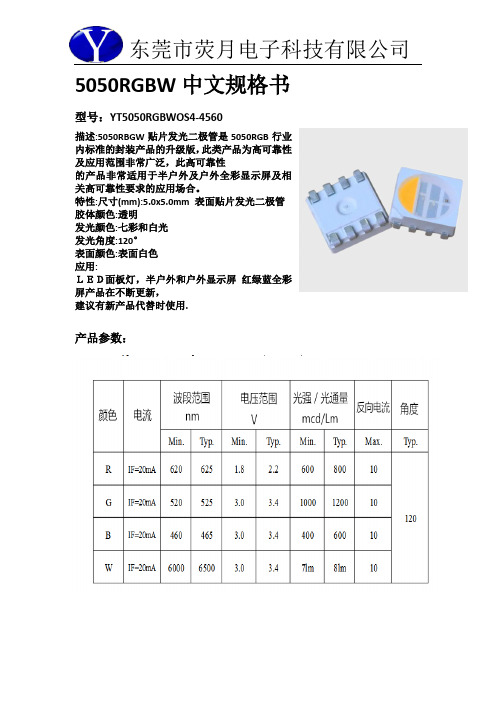
5050RGBW中文规格书型号:YT5050RGBWOS4-4560描述:5050RBGW贴片发光二极管是5050RGB行业内标准的封装产品的升级版,此类产品为高可靠性及应用范围非常广泛,此高可靠性的产品非常适用于半户外及户外全彩显示屏及相关高可靠性要求的应用场合。
特性:尺寸(mm):5.0x5.0mm 表面贴片发光二极管胶体颜色:透明发光颜色:七彩和白光发光角度:120°表面颜色:表面白色应用:LED面板灯,半户外和户外显示屏红绿蓝全彩屏产品在不断更新,建议有新产品代替时使用.产品参数:注意:所有尺寸单位为mm;如无特殊说明误差范围为±0.05mm 。
***应用注意事项特点本文件主要向顾客及用户介绍怎样如何更好的使用我司的SMD LED 产品。
描述一般来说,SMD 5050跟一般的半导体有相同的用法。
当使用荧月电子的SMD5050产品,请遵从以下的使用方法以保护SMD LED 产品。
1.清洁:不要使用不明化学液体清洗SMD LED,不明的化学液体可能会损坏SMDLED。
当必要清洗时,把SMD LED沉浸在酒精里,在正常的室温下少于1 分钟并且自然干燥15 分钟,然后才开始使用。
2.防潮湿包装为避免产品在运输及储存中吸湿,SMD LED 的包装是用防潮的铝包装袋包装,并且包装袋里面含有干燥剂及湿度卡,干燥剂主要起到控制包装袋里的湿度,湿度卡主要是起到监控包装袋里的湿度。
3.储存a.包装袋密封后贮存在条件为温度< 40℃,湿度< 60%RH,保存期为12 个月。
当超过保质期时,需要重新烘烤。
b.在开包装之前,请先检查包装袋有无漏气或湿度指示卡有无变色,如果有漏气或湿度指示卡有变色现象,请重新烘烤后再使用。
c.开封后请在以下条件使用:温度< 30℃、湿度在30%RH 以下;如果使用时间超出24小时,须做以下烘烤处理才可使用。
d.烘烤条件:产品在烘箱在温度为70℃±5℃;相对湿度≤10%RH,时间:24 小时。
molex产品介绍

模块类1,超五类内置防尘盖插座KSJ-00024-** PowerCat超五类DataGate Plus插座, 568A/B - 内置防尘盖MOD-Clip DataGate Plus和DataGate Plus插座采用“弹簧支撑的防尘盖”专利技术,可以防止尘土和杂质。
如果跳线插入不当,弹簧支撑的防尘盖会弹出。
而且,用户只需一只手就可以插拔跳线,操作非常简便。
顺序端接线对弹簧支撑的防尘盖专利技术,防止接插不当具有尖端IDC塔身,加快端接速度,增强电缆固定能力支持568A/B线序配置适合用于Synergy、Streamline、Signature和USO II系列墙板和盒子式插座,适合用于Molex的介质可配置配线架2,PowerCat超五类FTP插座KSJ-00012-02 PowerCat超五类FTP插座, RJ45, 568A/BowerCat超五类FTP插座是为在Molex企业布线网络部FTP DataGate配线架和Synergy或USO II系列墙板内使用而设计的。
PowerCat超五类FTP插座提供了全屏蔽超五类性能,具有黑色镀镍黄铜360°“全方位”屏蔽。
在端接过程中,屏蔽和加蔽线以机械方式接在电缆和360° “全方位”屏蔽之间,保证快速可靠的屏蔽连续性通用EIA 568A/B线序提供了360°全屏蔽性能用于未装上的PowerCat超五类FTP配线架内部六类模块KSJ-00018-** PowerCat 6六类DataGate Plus插座, 568A/BDataGate插座是为了保持稳固的连接而设计的。
RJ-45插座采用“弹簧支撑的防尘盖”专利技术,可以防止尘土和杂质。
如果跳线插入不当,弹簧支撑的防尘盖会弹出。
而且,用户只需一只手就可以插拔跳线,操作非常简便。
DataGate Plus插座分成11种颜色,它采用独特的IDC V形触点专利技术,触点可以伸缩,无论重新端接的次数有多少,此类模块均不易被损坏。
elan-tech AS 70 AW 70 100 50说明书
A member ofProduct InformationEN Elan-tech®AS 70/AW 70100:50ELANTAS EUROPE Sales offices:Strada Antolini n°1 loc. Lemignano 43044 Collecchio (PR)ItalyTel +39 0521 304777Fax +39 0521 804410Grossmannstr. 10520539 Hamburg GermanyTel +49 40 78946 0Fax +49 40 78946 349******************************Cartridges Kit ADH 70.702-component s self-extinguishing, thermal conductive, epoxy adhesive. Listed system UL 94 V-0 and UL 94 HBApplication:Thermal-conductive structural adhesive for metals and ceramic materials.Bonding/sealing of tools that need heat dissipation.Processing:Manual application by brush, by spatula or with mixing/dispensing devices.Description:Two components filled epoxy system with abrasive fillers.Thixotropic.Solvent free.Self-extinguishing according to UL94V-0on5,5mm thickness and according to UL94HB on1,6mm thickness.Excellentadhesive properties on all types of metals.Very good chemical resistance to engine oil and gasoline,acidsand bases.High thermal conductivity.High thermal resistance.The best characteristics are obtained afterstabilization of the product at60-70°C.The resin and the hardener have contrasting colours to make easythe control of the mixing.The system is RoHS compliant(European directive2002/95/EC)and the newRoHS Directive2011/65/EU(RoHS2)entered into force on21July2011and requires Member States totranspose the provisions into their respective national laws by 2 January 2013.SYSTEM SPECIFICATIONSMixing ratio by weightTYPICAL SYSTEM CHARACTERISTICSResin HardenerAS 70AW 70100:50 Structural adhesiveMixing ratio by volume Cartridges kit ADH 70.70100:50 PRODUCT INFORMATION pag.2/5TYPICAL CURED SYSTEM PROPERTIESProperties determined on specimens cured: 3 h RT + 6 h 80°C IO-00-00 = ELANTAS Europe's test method. The corresponding international method is indicated whenever possible.nd = not determined na = not applicable RT = TA = laboratory room temperature (23±2°C)Conversion units: 1 mPas = 1 cPs 1MN/m2 = 10 kg/cm2 = 1 MPa(*) for larger quantities pot life is shorter and exothermic peak increases (**) the brackets mean optionality(***)The maximum operating temperature is given on the basis of laboratory information available being it function of the curing conditions used and of the type of coupled materials. For further possible information see post-curing paragraph.A member ofEpoxy resins and their hardeners can be stored for two years in the original sealed containers stored in a cool,dry place.The hardeners are moisture sensitive therefore it is good practice to close the vessel immediately after each use.Prepare the surfaces to be bonded by removing moisture,dust,dirt and loose parts.For metals is normally enough a mechanical abrasion or sand blasting followed by degreasing with acetone.When gluing composite parts it is not required any specific surface treating other cleaning with acetone.In case of plastic substrate it is important to check its solvent resistance before cleaning.Generally is suggested a light sanding followed by cleaning with alcohol.Plasma or corona treatment will improve adhesion and consequently bonding strength:it's recommended in case of specific needs.Add the appropriate amount of hardener into the resin and mix carefully using a slow speed stirrer or by hand with a spatula.Apply the adhesive in a homogeneous thickness maintaining a uniform contact pressure on the joint.Before setting ,the adhesive is moisture and carbon dioxide:once applied cover the joined parts as soon as possible or,better,hot cure if possible.Further general information are available in the brochure “Elantech Adhesive &Sealants”.Post curing is always advisable for RT curing systems in order to stabilize the component and to reach the best properties. It is necessary when the component works at a high temperature.Instructions:Curing/Post-curing:Storage:Handling precautions:emission date:revision n° 00April2016The information given in this publication is based on the present state of our technical knowledge but buyers and users should make their own assessments of our products under their own application conditions.Refer to the safety data sheet and comply with regulations relating to industrial health and waste disposal.Manufactured: ELANTAS Europe S.r.l. Sito di Strada Antolini n°1, 43044 Collecchio (PR), ItalyA member ofPRODUCT INFORMATIONpag.5/5A member of。
- 1、下载文档前请自行甄别文档内容的完整性,平台不提供额外的编辑、内容补充、找答案等附加服务。
- 2、"仅部分预览"的文档,不可在线预览部分如存在完整性等问题,可反馈申请退款(可完整预览的文档不适用该条件!)。
- 3、如文档侵犯您的权益,请联系客服反馈,我们会尽快为您处理(人工客服工作时间:9:00-18:30)。
○
---
24 C
5.28 505070-2242
○
---
22
4.93 505070-2042
○
---
20
16
0.64
1.14
21.4
17.4
4.58 4.23
505070-1842 505070-1642
--○
---
18
---
16
3.88 505070-1442
○
---
14
3.53 505070-1242
○ ---
---
48
---
46
8.78 505070-4242
○
---
42
8.43 505070-4042
○
---
40
7.38 505070-3442
○
7.03 505070-3242
---
---
34
B
---
32
キャリアテープ幅 CARRIER TAPE WIDTH
C
B
(A)
MATERIAL No.
mm 2:1
GENERAL TOLERANCES
(UNLESS SPECIFIED)
ANGULAR TOL ± 1.0 ° EC NO: 612826
4 PLACES
± 0.01 DRWN: GSHARMA CHK'D: MSASAO
3 PLACES
± 0.03 APPR: MSASAO
2 PLACES ± 0.05 INITIAL REVISION:
HIGH VOL TOOL LOW VOL TOOL SAMPLE PREPARATION
CIRCUIT
THIS DRAWING CONTAINS INFORMATION THAT IS PROPRIETARY TO MOLEX ELECTRONIC TECHNOLOGIES, LLC AND SHOULD NOT BE USED WITHOUT WRITTEN PERMISSION
术支支持请联系深圳市合创立立
科技有限公司
18319055722
7
6
5
B
MODEL NO. 505070-**42
THIS DRAWING CONTAINS INFORMATION THAT IS PROPRIETARY TO MOLEX ELECTRONIC TECHNOLOGIES, LLC AND SHOULD NOT BE USED WITHOUT WRITTEN PERMISSION
A3-SIZE 505070
GENERAL
2 OF 3
7
6
5
4
3
2
1
10 F E
D
9
8
7
6
5
PULL OUT DIRECTION TOP TAPE
(2.16) (1.08)
Y
(A)
24 ±0.3 (11.5)
(A)
0.3 ±0.05 (1.14)
SECTION Y-Y
X
1.75 ±0.1
⌀ 1.5 ±0.1
REVISION: H
9
8
7
DATE: 2018/01/18
12.63 505070-6442
---
---
64 C
11.93 505070-6042
---
---
60
10.88 505070-5442
○
---
54
10.18 505070-5042
○
---
50
24
29.4 25.4
9.83 9.48
505070-4842 505070-4642
FITTING NAIL :
CONTACT AREA: SEPARATED GOLD PLATING
(0.1 MICROMETER MINIMUM).
SOLDER TAIL AREA: SEPARATED GOLD PLATING.
B
UNDERPLATE: NICKEL OVERALL.
*DIVIDE INTO PARTS THE GOLD PALATING OF THE CONTACT
�120°�
�2�
B
(⌀ 21)
�⌀ 13�
DETAIL "D" A
DOCUMENT STATUS
10 FORMAT: master-tb-prod-A3
REVISION: H DATE: 2018/01/18
P1
RELEASE DATE 2019/02/27
9
05:28:37
8
molex连接器器产品信息及技
CIRCUIT
THIS DRAWING CONTAINS INFORMATION THAT IS PROPRIETARY TO MOLEX ELECTRONIC TECHNOLOGIES, LLC AND SHOULD NOT BE USED WITHOUT WRITTEN PERMISSION
DIMENSION UNITS SCALE CURRENT REV DESC: REVISED
APPR: TKUSUHARA01
THIRD ANGLE PROJECTION
DRAWING
A3-SIZE
3
2019/02/22
0.35 BB CONN. H=0.6 SSB6 RP PLUG ASSY
2019/02/27
2019/02/27
PRODUCT CUSTOMER DRAWING
A
DOCUMENT NUMBER
D
1 MATERIAL
WAFER:LIQUID CRYSTAL POLYMER UL94V-0(COLOR :BLACK)
TERMINAL:COPPER ALLOY
FITTING NAIL : COPPER ALOY
2 PLATING
TERMINAL :
C
CONTACT AREA: SEPARATED GOLD PLATING
1 PLACE
± 0.1
0 PLACES
± 0.2
DRAFT WHERE APPLICABLE MUST REMAIN
WITHIN DIMENSIONS
4
EC NO: 612826
DRWN: GSHARMA
CHK'D: MSASAO
APPR: MSASAO
INITIAL REVISION:
DRWN: TNISHIDA02
10
9
8
F PULL OUT DIRECTION
E
7 REEL
6
5
4
3
2
1
NOTES
1.
RE DETAILED DIMENSION, SEE PRODUCT DRAWING.
F
2.
NUMBER OF CONNECTORS : 8000 PCS/REEL.
3.
LEAD TAPE LENGTH.
20PCS. MIN. TOP TAPE BONDED PART.(EMPTY)
2019/02/22
0.35 BB CONN. H=0.6 SSB6 RP PLUG ASSY
2019/02/27
2019/02/27
PRODUCT CUSTOMER DRAWING
A
DOCUMENT NUMBER
DOC TYPE DOC PART REVISION
1 PLACE 0 PLACES
± 0.1 DRWN: TNISHIDA02 ± 0.2 APPR: TKUSUHARA01
DIMENSION UNITS SCALE CURRENT REV DESC: REVISED
mm 1:5
GENERAL TOLERANCES (UNLESS SPECIFIED)
ANGULAR TOL ± 1.0 °
4 PLACES
± 0.01
3 PLACES
± 0.03
2 PLACES
± 0.05
DIMENSION UNITS SCALE CURRENT REV DESC: REVISED
mm 2:1
GENERAL TOLERANCES
(UNLESS SPECIFIED)
ANGULAR TOL ± 1.0 ° EC NO: 612826
4 PLACES
± 0.01 DRWN: GSHARMA CHK'D: MSASAO
(0.1 MICROMETER MINIMUM).
SOLDER TAIL AREA: SEPARATED GOLD PLATING.
UNDERPLATE: NICKEL OVERALL.
*DIVIDE INTO PARTS THE GOLD PLATING OF THE CONTACT
AND THE TAIL PART BY THE NICKEL PLATING.
DRAAL NUMBER
CUSTOMER
SHEET NUMBER
MUST REMAIN WITHIN DIMENSIONS
A3-SIZE 505070
GENERAL
3 OF 3
6
5
4
3
2
1
2 1.26 ±0.2
0.7 (PICKING AREA) 0.48
10 F
9 0.405 ±0.1
○
---
12
3.18 505070-1042
○
---
10
2.78 505070-0842
