ansys教程
ANSYS新手入门手册(完整版)超值上
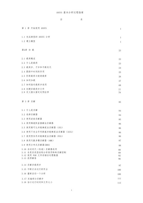
ANSYS 基本分析过程指南目录第 1 章开始使用 ANSYS1.1 完成典型的 ANSYS 分析1.2 建立模型第2章加载2.1 载荷概述2.2 什么是载荷2.3 载荷步、子步和平衡迭代2.4 跟踪中时间的作用2.5 阶跃载荷与坡道载荷2.6 如何加载2.7 如何指定载荷步选项2.8 创建多载荷步文件2.9 定义接头固定处预拉伸第 3 章求解3.1 什么是求解3.2 选择求解器3.3 使用波前求解器3.4 使用稀疏阵直接解法求解器3.5 使用雅可比共轭梯度法求解器(JCG)3.6 使用不完全乔列斯基共轭梯度法求解器(ICCG)3.7 使用预条件共轭梯度法求解器(PCG)3.8 使用代数多栅求解器(AMG)3.9 使用分布式求解器(DDS)3.10 自动迭代(快速)求解器选项3.11 在某些类型结构分析使用特殊求解控制3.12 使用 PGR 文件存储后处理数据3.13 获得解答3.14 求解多载荷步3.15 中断正在运行的作业3.16 重新启动一个分析3.17 实施部分求解步3.18 估计运行时间和文件大小111 2323 23 24 25 26 27 6877 788584 84 85 86 86 86 86 87 8888 89 92 9697 100 100 111 1133.19 奇异解第 4 章后处理概述4.1 什么是后处理4.2 结果文件4.3 后处理可用的数据类型第5章5.1 概述5.2 将数据结果读入数据库5.3 在 POST1 中观察结果5.4 在 POST1 中使用 PGR 文件5.5 POST1 的其他后处理内容第 6 章时间历程后处理器(POST26)6.1 时间历程变量观察器6.2 进入时间历程处理器6.3 6.4 6.5 6.6 6.7定义变量处理变量并进行计算数据的输入数据的输出变量的评价通用后处理器(POST1)1141161161171171181181181271521601741741761771791811831841871901901901941956.8 POST26 后处理器的其它功能第 7 章选择和组件7.1 什么是选择7.2 选择实体7.3 为有意义的后处理选择7.4 将几何项目组集成部件与组件第 8 章图形使用入门8.1 概述8.2 交互式图形与“外部”图形8.3 标识图形设备名(UNIX 系统)8.4 指定图形显示设备的类型(WINDOWS 系统)198198 198 198 2018.5 与系统相关的图形信息8.6 产生图形显示8.7 多重绘图技术第 9 章通用图形规范9.1 概述9.2 用 GUI 控制显示9.3 多个 ANSYS 窗口,叠加显示9.4 改变观察角、缩放及平移9.5 控制各种文本和符号9.6 图形规范杂项9.7 3D 输入设备支持第 10 章增强型图形10.1 图形显示的两种方法10.2 POWERGRAPHICS 的特性10.3 何时用 POWERGRAPHICS10.4 激活和关闭 POWERGRAPHICS10.5 怎样使用 POWERGRAPHICS10.6 希望从 POWERGRAPHICS 绘图中做什么第 11 章创建几何显示11.1 用 GUI 显示几何体11.2 创建实体模型实体的显示11.3 改变几何显示的说明第 12 章创建几何模型结果显示12.1 利用 GUI 来显示几何模型结果12.2 创建结果的几何显示12.3 改变 POST1 结果显示规范12.4 Q-SLICE 技术12.5 等值面技术12.6 控制粒子流或带电粒子的轨迹显示202 205 207210210 210 210 211 214 217 218219219 219 219 220 220 220223223 223 224233233 233 235 238 238 239第 13 章生成图形24013.1 使用 GUI 生成及控制图13.2 图形显示动作13.3 改变图形显示指定第 14 章注释注释概述二维注释为 ANSYS 模型生成注释三维注释三维查询注释240 240 24124514.1 14.2 14.3 14.4 14.5245 245 246 246 247第 15 章动15.1 动画概述画24824824824824924925025115.2 在 ANSYS 中生成动画显示15.3 使用基本的动画命令15.4 使用单步动画宏15.5 离线捕捉动画显示图形序列15.6 独立的动画程序15.7 WINDOWS 环境中的动画第 16 章外部图形25316.1 外部图形概述16.2 生成中性图形文件16.3 DISPLAY 程序观察及转换中性图形文件16.4 获得硬拷贝图形第 17 章报告生成器17.1 启动报告生成器17.2 抓取图象17.3 捕捉动画17.4 获得数据表格17.5 获取列表17.6 生成报告253 254 255 258259259 260 260 261 264 26417.7 报告生成器的默认设置第 18 章 CMAP 程序18.1 CMAP 概述18.2 作为独立程序启动 CMAP 18.3 在 ANSYS 内部使用 CMAP 18.4 用户化彩色图第 19 章文件和文件管理267 269269 269 271 27127419.1 文件管理概述19.2 更改缺省文件名19.3 将输出送到屏幕、文件或屏幕及文件19.4 文本文件及二进制文件19.5 将自己的文件读入 ANSYS 程序19.6 在 ANSYS 程序中写自己的 ANSYS 文件19.7 分配不同的文件名19.8 观察二进制文件内容(AXU2)19.9 在结果文件上的操作(AUX3)19.10 其它文件管理命令第 20 章内存管理与配置20.1 内存管理20.2 基本概念20.3 怎样及何时进行内存管理20.4 配置文件274274 275 275 278 279 280280 280280 282282 282 283 286第1章开始使用 ANSYS1.1 完成典型的 ANSYS 分析ANSYS 软件具有多种有限元分析的能力,包括从简单线性静态分析到复杂的非线性瞬态动力学分析。
《ANSYS教程》课件
2000年代
推出ANSYS Workbench,实 现多物理场耦合分析。
1970年代
ANSYS公司成立,开始开发有 限元分析(FEA)软件。
1990年代
扩展软件功能,增加流体动力 学、电磁场等分析模块。
2010年代
持续更新和优化,加强与CAD 软件的集成,提高计算效率和 精度。
软件应用领域
航空航天
2023
PART 07
后处理与可视化
REPORTING
结果查看与图表生成
结果查看
通过后处理,用户可以查看分析结果,如应力、应变、位移等。
图表生成
根据分析结果,可以生成各种类型的图表,如柱状图、曲线图、等值线图等,以便更直观地展示结果 。
可视化技术
云图显示
通过云图显示,可以清晰地展示模型 的应力、应变分布情况。
压力载荷等。
在设置边界条件和载荷 时,需要考虑实际工况 和模型简化情况,确保 分析的准确性和可靠性
。
求解和后处理
求解是ANSYS分析的核心步骤,通过求解可以得到模型在给定边界条件和 载荷下的响应。
ANSYS提供了多种求解器,如稀疏矩阵求解器、共轭梯度求解器等,可以 根据需要进行选择。
后处理是分析完成后对结果的查看和处理,ANSYS提供了丰富的后处理功 能,如云图显示、动画显示等。
VS
详细描述
非线性分析需要使用更复杂的模型和算法 ,以模拟结构的非线性行为。通过非线性 分析,可以更准确地预测结构的极限载荷 和失效模式,对于评估结构的可靠性和安 全性非常重要。
2023
PART 04
流体动力学分析
REPORTING
流体静力学分析
静力学分析用于研究流体在静 止或准静止状态下的压力、应
有限元分析ANSYS简单入门教程

有限元分析ANSYS简单入门教程有限元分析(finite element analysis,简称FEA)是一种数值分析方法,广泛应用于工程设计、材料科学、地质工程、生物医学等领域。
ANSYS是一款领先的有限元分析软件,可以模拟各种复杂的结构和现象。
本文将介绍ANSYS的简单入门教程。
1.安装和启动ANSYS2. 创建新项目(Project)点击“New Project”,然后输入项目名称,选择目录和工作空间,并点击“OK”。
这样就创建了一个新的项目。
3. 建立几何模型(Geometry)在工作空间内,点击左上方的“Geometry”图标,然后选择“3D”或者“2D”,根据你的需要。
在几何模型界面中,可以使用不同的工具进行绘图,如“Line”、“Rectangle”等。
4. 定义材料(Material)在几何模型界面中,点击左下方的“Engineering Data”图标,然后选择“Add Material”。
在材料库中选择合适的材料,并输入必要的参数,如弹性模量、泊松比等。
5. 设置边界条件(Boundary Conditions)在几何模型界面中,点击左上方的“Analysis”图标,然后选择“New Analysis”并选择适合的类型。
然后,在右侧的“Boundary Conditions”面板中,设置边界条件,如约束和加载。
6. 网格划分(Meshing)在几何模型界面中,点击左上方的“Mesh”图标,然后选择“Add Mesh”来进行网格划分。
可以选择不同的网格类型和规模,并进行调整和优化。
7. 定义求解器(Solver)在工作空间内,点击左下方的“Physics”图标,然后选择“Add Physics”。
选择适合的求解器类型,并输入必要的参数。
8. 运行求解器(Run Solver)在工作空间内,点击左侧的“Solve”图标。
ANSYS会对模型进行求解,并会在界面上显示计算过程和结果。
ANSYS基本操作精讲

ANSYS基本操作精讲
1. 新建项目:启动ANSYS后,点击“File -> New -> Project…”,输入项目名称和存储路径,选择适当的单位系统和求解器类型,然后点击“OK”按钮。
3.定义材料属性:在材料模块中,可以定义各种材料的物理特性。
选
择合适的材料模型并输入相应的参数。
可以通过导入材料库或自定义材料
属性来定义材料。
4.设置边界条件:在加载模块中,设置边界条件是非常重要的。
可以
设置约束条件(如固定支撑和约束)和荷载条件(如力、压力和热源)。
通过选择几何模型的面、边或节点,然后定义相应的边界条件。
5.网格划分:网格划分模块(或称为前处理模块)用于将几何模型离
散化为有限元网格。
可以选择适当的网格类型,如三角形网格或四边形网格,并选择合适的网格密度。
6. 运行求解器:在求解模块中,选择适当的求解器和求解方法。
通
过点击“Solve”按钮,ANSYS将自动进行求解,并输出结果。
可以通过
设置收敛准则、调整步长和监控求解过程来改进求解性能。
7.结果后处理:在后处理模块中,可以对求解结果进行可视化和分析。
可以使用绘图工具绘制各种图表和图形,并对结果进行剪切、比较和动态
显示。
以上是ANSYS的一些基本操作。
除了这些基本操作外,ANSYS还提供
了许多高级功能和工具来解决复杂的工程问题。
为了更好地使用ANSYS,
建议深入学习ANSYS的使用手册和相关教程,并进行实际的案例分析和实
践操作。
ANSYS入门教程
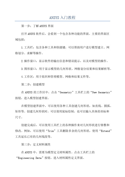
ANSYS入门教程第一步:了解ANSYS界面打开ANSYS软件后,会看到一个包含各种功能的界面。
主要的界面区域包括:1.工具栏:包含各种工具和快捷键,可以帮助用户进行模型建立、网格划分、求解等操作。
2.操作窗口:显示软件的输出信息和错误提示,以及对模型的操作。
3.图形窗口:用于显示模型的几何形状、网格划分结果和结果解析等。
4.工作区:用于组织和管理模型、网格和结果文件等。
第二步:创建模型在ANSYS的工作区中,点击“Geometry”工具栏上的“New Geometry”按钮,进入模型创建界面。
在模型创建界面中,可以使用各种工具创建几何形状,如直线、圆弧、矩形等。
创建几何形状时,可以使用鼠标绘制,也可以输入具体的坐标和尺寸。
创建完成后,可以使用工具栏上的各种操作来对几何形状进行修整和修改。
例如,可以使用“Trim”工具删除多余的几何形状,使用“Extend”工具延长已有的几何线段等。
第三步:定义材料属性在ANSYS中,需要为模型定义材料属性。
点击工具栏上的“Engineering Data”按钮,进入材料属性定义界面。
在界面中,可以选择不同的材料类型,并输入相应的参数,如杨氏模量、泊松比等。
还可以导入外部材料库中的材料属性数据。
第四步:划分网格在ANSYS中,需要将模型划分为小的网格单元,以便进行后续的有限元分析。
点击工具栏上的“Mesh”按钮,进入网格划分界面。
在界面中,可以选择不同的网格类型,并设置相应的网格参数。
通常,可以选择“Quad”或“Tri”网格类型,并设置网格大小。
完成网格划分后,可以使用工具栏上的网格修整工具来调整和修改网格。
第五步:施加边界条件在ANSYS中,需要为模型施加边界条件和加载。
点击工具栏上的“Solution”按钮,进入边界条件设置界面。
在界面中,可以选择不同的加载类型,并设置相应的加载参数。
例如,可以选择“Force”加载,并输入加载的大小和方向。
还可以选择“Constraint”加载,并设置固定边界条件。
ANSYS模态分析教程及实例讲解解析
ANSYS模态分析教程及实例讲解解析ANSYS是一个广泛应用于工程领域的有限元分析软件,可以用于各种结构的模态分析,包括机械结构、建筑结构、航空航天结构等。
模态分析是通过计算结构的固有频率和振动模态,用于评估结构的动力特性和振动响应。
以下是一个ANSYS模态分析的教程及实例讲解解析。
一、教程:ANSYS模态分析步骤步骤1:建立模型首先,需要使用设计软件绘制或导入一个几何模型。
然后,在ANSYS中选择适当的单元类型和材料属性,并创建适当的网格。
确保模型的几何形状和尺寸准确无误。
步骤2:约束条件在进行模态分析之前,需要定义适当的约束条件。
这些条件包括固定支持的边界条件、约束点的约束类型、约束方向等。
约束条件的选择应该与实际情况相符。
步骤3:施加载荷根据实际情况,在模型上施加适当的载荷。
这些载荷可以是静态载荷、动态载荷或谐振载荷,具体取决于所要分析的问题。
步骤4:设置分析类型在ANSYS中,可以选择多种不同的分析类型,包括静态分析、模态分析、动态响应分析等。
在进行模态分析时,需要选择模态分析类型,并设置相应的参数。
步骤5:运行分析设置好分析类型和参数后,可以运行分析。
ANSYS将计算结构的固有频率和振动模态。
运行时间取决于模型的大小和复杂性。
步骤6:结果分析完成分析后,可以查看和分析计算结果。
ANSYS将生成包括固有频率、振动模态形态、振动模态形状等在内的结果信息。
可以使用不同的后处理技术,如模态形态分析、频谱分析等,对结果进行更详细的分析。
二、实例讲解:ANSYS模态分析以下是一个机械结构的ANSYS模态分析的实例讲解:实例:机械结构的模态分析1.建立模型:使用设计软件绘制机械结构模型,并导入ANSYS。
2.约束条件:根据实际情况,将结构的一些部分设置为固定支持的边界条件。
3.施加载荷:根据实际应用,施加恰当的静态载荷。
4.设置分析类型:在ANSYS中选择模态分析类型,并设置相应的参数,如求解方法、迭代次数等。
Ansys基础教程

Create > -Lines- Lines
Create > -Lines- Arcs
Create > -Lines- Splines
L,k1,k2
L,k1,k2,k3,radius
面
• 用由下向上的方法生成面时, 需要的关键点或线必须已经定义。 (A——关键点〔顺序〕、AL——线)
可以根据模型形状选择最佳建模途径.
下面详细讨论建模途径。
实体建模 B. 自顶向下建模
• 自顶向下建模: 首先建立高级图元(体或 面),对这些高级图元(体或面)按一定规 则组合得到最终需要的形状.
• 开始建立的体或面称为图元。 • 生成一种体素时会自动生成所有的从属于
该体素的较低级图元。 • 对几何图元进行组合计算形成最终形状的
ANSYS教程
ANSYS 结构分析
第一章 ANSYS主要功能与模块
• ANSYS是世界上著名的大型通用有 限元计算软件, 它包括热、电、磁、流体和 结构等诸多模块, 具有强大的求解器和前、 后处理功能, 为我们解决复杂、庞大的工程 项目和致力于高水平的科研攻关提供了一 个优良的工作环境, 是一个开放的软件, 支 持进行二次开发。 • 目前主流版本12.0,13.0,14.0,14.5
一、主要功能简介
• 1. 结构分析
• 1) 静力分析 – 求解静力载荷作用下结 构的位移和应力等. 可以考虑结构的线性及 非线性行为。
• ● 线性结构静力分析 (linear)
• ● 非线性结构静力分析 (nonlinear)
•
♦ 几何非线性: 大变形、大应变、
应力强化、旋转软化
•
♦ 材料非线性: 塑性、粘弹性、粘
ANSYS中文教程

第1章ANSYS 基本介绍1.1 ANSYS 6.1 的安装1.2 ANSYS 6.1 的启动和配置1.3 ANSYS 界面介绍1.4 ANSYS 输出文件第 2 章建立模型2.1 设置工作目录2.2 指定作业名和分析标题2.3 定义图形界面过滤参数2.4 ANSYS 的单位制2.5 定义单元类型2.6 定义单元实常数2.7 定义材料属性2.8 关于建立模型的基本概念2.9 坐标系2.10 实体建模2.11 对实体模型划分网格2.12 耦合和约束2.13 模型的合并和归档第三章加载和求解3.1 加载3.2 求解第四章后处理4.1 通用后处理器4.2 单元表4.3 路径4.4 时间历程后处理器第五章六方孔螺钉投用扳手的静力分析5.1 问题描述5.2 建立模型5.3 定义边条并求解5.4 查看结果5.5 命令流输入第六章缺失第七章平面问题分析实例7.1 问题描述7.2 建立模型7.3 定义边条并求解7.4 查看结果7.5 命令流输入第八章轴对称结构的静力分析8.1 问题描述8.2 建立模型8.3 定义边条并求解8.4 查看结果8.5 命令流输入第九章周期对称结构的静力分析9.1 问题描述9.2 建立模型9.3 定义边条并求解9.4 查看结果9.5 命令流输入第10 章动力学分析介绍10.1 动力分析简介10.2 动力学分析分类10.3 各类动力学分析的基本步骤第11 章有预应力作用结构的模态分析实例11.1 问题描述11.2 建立模型11.3 定义边条并求解11.4 结果分析11.5 命令流输入第12 章周期对称结构的模态分析12.1 问题描述12.2 建立模型12.3 定义边条并求解12.4 查看结果12.5 命令流输入第13 章有预应力作用结构的谐响应实例13.1 问题描述13.2 建立模型13.3 定义边条、加载并求解13.4 观察分析结果13.5 命令流输入第十四章瞬态结构动力分析实例14.1 问题描述14.2 建立模型14.3 定义边条、加载并求解14.4 观察分析结果14.5 命令流输入第15 章随机振动和随机疲劳分析实例15.1 问题描述15.2 建立模型15.3 定义边条、加载并求解15.4 观察分析结果15.5 命令流输入第16 章单点响应谱分析实例16.1 问题描述16.2 建立模型16.3 定义边条、加载并求解16.4 观察分析结果第17 章非线性结构分析17.1 非线性结构分析简介17.2 非线性结构分析的分析过程17.3 几何非线性17.4 材料非线性17.5 状态非线性第18 章非线性瞬态实例分析18.1 问题描述18.2 建立模型18.3 定义分析类型、加载并求解18.4 观察分析结果18.5 非线性瞬态分析命令流第19 章塑性分析实例19.1 问题描述19.2 建立有限元模型19.3 加载并求解19.4 结果分析17.5 塑性实例分析的命令流方式第20 章接触分析实例20.1 问题描述20.2 建立有限元模型。
ANSYS新手入门手册(完整版)超值上
ANSYS新手入门手册(完整版)超值上ANSYS 基本分析过程指南目录第 1 章开始使用 ANSYS1.1 完成典型的 ANSYS 分析1.2 建立模型第2章加载2.1 载荷概述2.2 什么是载荷2.3 载荷步、子步和平衡迭代2.4 跟踪中时间的作用2.5 阶跃载荷与坡道载荷2.6 如何加载2.7 如何指定载荷步选项2.8 创建多载荷步文件2.9 定义接头固定处预拉伸第 3 章求解3.1 什么是求解3.2 选择求解器3.3 使用波前求解器3.4 使用稀疏阵直接解法求解器3.5 使用雅可比共轭梯度法求解器(JCG)3.6 使用不完全乔列斯基共轭梯度法求解器(ICCG)3.7 使用预条件共轭梯度法求解器(PCG)3.8 使用代数多栅求解器(AMG)3.9 使用分布式求解器(DDS)3.10 自动迭代(快速)求解器选项3.11 在某些类型结构分析使用特殊求解控制3.12 使用 PGR 文件存储后处理数据3.13 获得解答3.14 求解多载荷步3.15 中断正在运行的作业3.16 重新启动一个分析3.17 实施部分求解步3.18 估计运行时间和文件大小111 2323 23 24 25 26 27 6877 788584 84 85 86 86 86 86 87 8888 89 92 9697 100 100 111 1133.19 奇异解第 4 章后处理概述4.1 什么是后处理4.2 结果文件4.3 后处理可用的数据类型第5章5.1 概述5.2 将数据结果读入数据库5.3 在 POST1 中观察结果5.4 在 POST1 中使用 PGR 文件5.5 POST1 的其他后处理内容第 6 章时间历程后处理器(POST26)6.1 时间历程变量观察器6.2 进入时间历程处理器6.3 6.4 6.5 6.6 6.7定义变量处理变量并进行计算数据的输入数据的输出变量的评价通用后处理器(POST1)1141161161171171181181181271521601741741761771791811831841871901901901941956.8 POST26 后处理器的其它功能第 7 章选择和组件7.1 什么是选择7.2 选择实体7.3 为有意义的后处理选择7.4 将几何项目组集成部件与组件第 8 章图形使用入门8.1 概述8.2 交互式图形与“外部”图形8.3 标识图形设备名(UNIX 系统)8.4 指定图形显示设备的类型(WINDOWS 系统)198198 198 198 2018.5 与系统相关的图形信息8.6 产生图形显示8.7 多重绘图技术第 9 章通用图形规范9.1 概述9.2 用 GUI 控制显示9.3 多个 ANSYS 窗口,叠加显示9.4 改变观察角、缩放及平移9.5 控制各种文本和符号9.6 图形规范杂项9.7 3D 输入设备支持第 10 章增强型图形10.1 图形显示的两种方法10.2 POWERGRAPHICS 的特性10.3 何时用 POWERGRAPHICS10.4 激活和关闭 POWERGRAPHICS10.5 怎样使用 POWERGRAPHICS10.6 希望从 POWERGRAPHICS 绘图中做什么第 11 章创建几何显示11.1 用 GUI 显示几何体11.2 创建实体模型实体的显示11.3 改变几何显示的说明第 12 章创建几何模型结果显示12.1 利用 GUI 来显示几何模型结果12.2 创建结果的几何显示12.3 改变 POST1 结果显示规范12.4 Q-SLICE 技术12.5 等值面技术12.6 控制粒子流或带电粒子的轨迹显示202 205 207 210210 210 210 211 214 217 218219219 219 219 220 220 220223223 223 224233233 233 235 238 238 239第 13 章生成图形24013.1 使用 GUI 生成及控制图13.2 图形显示动作13.3 改变图形显示指定第 14 章注释注释概述二维注释为 ANSYS 模型生成注释三维注释三维查询注释240 240 24124514.1 14.2 14.3 14.4 14.5245 245 246 246 247第 15 章动15.1 动画概述画24824824824824924925025115.2 在 ANSYS 中生成动画显示15.3 使用基本的动画命令15.4 使用单步动画宏15.5 离线捕捉动画显示图形序列15.6 独立的动画程序15.7 WINDOWS 环境中的动画第 16 章外部图形25316.1 外部图形概述16.2 生成中性图形文件16.3 DISPLAY 程序观察及转换中性图形文件16.4 获得硬拷贝图形第 17 章报告生成器17.1 启动报告生成器17.2 抓取图象17.3 捕捉动画17.4 获得数据表格17.5 获取列表17.6 生成报告253 254 255 258259259 260 260 261 264 26417.7 报告生成器的默认设置第 18 章 CMAP 程序18.1 CMAP 概述18.2 作为独立程序启动 CMAP 18.3 在 ANSYS 内部使用 CMAP 18.4 用户化彩色图第 19 章文件和文件管理267 269269 269 271 27127419.1 文件管理概述19.2 更改缺省文件名19.3 将输出送到屏幕、文件或屏幕及文件19.4 文本文件及二进制文件19.5 将自己的文件读入 ANSYS 程序19.6 在 ANSYS 程序中写自己的 ANSYS 文件19.7 分配不同的文件名19.8 观察二进制文件内容(AXU2)19.9 在结果文件上的操作(AUX3)19.10 其它文件管理命令第 20 章内存管理与配置20.1 内存管理20.2 基本概念20.3 怎样及何时进行内存管理20.4 配置文件274274 275 275 278 279 280280 280280 282282 282 283 286第1章开始使用 ANSYS1.1 完成典型的 ANSYS 分析ANSYS 软件具有多种有限元分析的能力,包括从简单线性静态分析到复杂的非线性瞬态动力学分析。
ANSYS仿真与分析系统入门教程
ANSYS仿真与分析系统入门教程第一章:ANSYS仿真与分析系统概述1.1 ANSYS仿真与分析系统的定义和作用1.2 ANSYS仿真与分析系统的历史和发展1.3 ANSYS仿真与分析系统的应用领域第二章:ANSYS仿真与分析系统的基本原理2.1 有限元分析方法2.2 基本原理和概念的介绍2.3 ANSYS仿真与分析系统的工作流程第三章:ANSYS仿真与分析系统的基本操作3.1 ANSYS仿真与分析系统的安装和启动3.2 创建和设置仿真模型3.3 导入和编辑几何模型3.4 定义边界条件和加载条件3.5 选择材料属性3.6 网格划分和生成3.7 设置求解器和求解选项3.8 运行仿真分析3.9 结果后处理和分析第四章:ANSYS仿真与分析系统的高级应用4.1 基于ANSYS仿真与分析系统的结构分析4.2 基于ANSYS仿真与分析系统的流体分析4.3 基于ANSYS仿真与分析系统的热传导分析4.4 基于ANSYS仿真与分析系统的电磁场分析4.5 基于ANSYS仿真与分析系统的多物理场耦合分析第五章:ANSYS仿真与分析系统案例分析5.1 结构分析案例分析5.2 流体分析案例分析5.3 热传导分析案例分析5.4 电磁场分析案例分析5.5 多物理场耦合分析案例分析第六章:ANSYS仿真与分析系统的应用展望6.1 ANSYS仿真与分析系统的发展趋势6.2 ANSYS仿真与分析系统的应用前景6.3 ANSYS仿真与分析系统的挑战与解决方案第一章:ANSYS仿真与分析系统概述ANSYS仿真与分析系统是一种基于有限元分析方法的工程仿真软件,用于模拟与分析物理系统的行为。
它提供了一种模拟真实世界工程问题的方式,能够对结构、流体、热传导、电磁场等多种物理场进行分析和优化。
ANSYS仿真与分析系统已经在汽车、航空航天、能源、电子、医疗等领域得到广泛的应用。
第二章:ANSYS仿真与分析系统的基本原理ANSYS仿真与分析系统基于有限元分析方法,将连续物体离散为有限个单元,通过求解单元边界上的方程来模拟整个物理系统的行为。
ansys教程

ansys教程ANSYS是一种通用的有限元分析(FEA)软件,可用于模拟和分析各种物理现象和工程问题。
它具有强大的模拟能力,可以模拟结构力学、流体力学、热传导、电磁等多个领域的问题。
本教程将为读者介绍如何使用ANSYS进行基本的有限元分析,并包含以下内容:第一部分:ANSYS介绍本节将介绍ANSYS的基本概念和核心功能,包括有限元分析的原理和步骤,ANSYS的安装和界面介绍等。
第二部分:模型建立本节将讲解如何使用ANSYS建立模型,包括几何建模和网格划分,以及如何导入外部模型。
第三部分:边界条件和加载本节将介绍如何定义边界条件和加载条件,包括约束条件、外部力和热辐射等。
第四部分:网格生成和求解本节将讲解如何进行网格生成和求解,包括网格生成器的选择和参数设置,以及求解器的选择和设置。
第五部分:结果分析本节将介绍如何分析并解释ANSYS的结果输出,包括应力、位移、温度等。
第六部分:高级功能本节将介绍ANSYS的一些高级功能,如优化、参数化和动态分析等。
第七部分:实例分析本节将通过一些实际案例来演示如何使用ANSYS解决工程问题,包括结构强度、流体流动等。
本教程将使用ANSYS的最新版本进行讲解,读者可以根据自己对ANSYS的需求选择相应的版本。
同时,在教程中还会提供一些ANSYS的使用技巧和注意事项,以帮助读者更好地掌握和应用ANSYS。
在学习和使用ANSYS时,读者需要具备基本的工程力学和数学知识,并具备一定的计算机和编程基础。
同时,由于ANSYS是一款功能强大且复杂的软件,初学者可能需要花费一些时间来熟悉和掌握它的使用方法。
总之,本教程将为读者提供一个系统和全面的学习ANSYS的指南,帮助读者快速入门并能独立使用ANSYS进行工程分析和模拟。
希望读者能通过本教程充分了解和掌握ANSYS的功能和应用,提高工程问题的解决能力。
如果读者能够深入研究并掌握ANSYS,将为其未来的工作和研究提供极大的帮助。
ansys使用教程
ansys使用教程ANSYS使用教程ANSYS是广泛应用于工程领域的有限元分析软件,可以模拟各种结构、流体、电磁和多物理场的行为。
本教程将介绍如何使用ANSYS进行基本的静态结构分析。
1. 安装和启动ANSYS- 下载并安装ANSYS软件,并获取有效的许可证。
- 双击桌面上的ANSYS图标启动软件。
2. 创建新工程- 在菜单栏中选择“File”>“New”>“Jobname”,输入工程名称,并选择默认的工作文件夹。
- 在主界面的“Project Schematic”中右键单击“Geometry”>“Create Geometry”,选择相应的几何模型创建方法。
3. 导入几何模型- 在几何模块中选择“File”>“Import”,选择要导入的几何文件(如STEP、IGES等)。
- 在弹出的导入向导中,选择适当的选项进行导入。
4. 定义材料属性- 在工程树中选择“Engineering Data”>“Materials”>“Create”。
- 输入材料名称,选择材料类型,输入材料属性(如弹性模量、泊松比等)。
5. 定义边界条件- 在工程树中选择“Analysis Settings”>“StepSettings”>“Boundary Conditions”>“Apply”。
- 选择要应用边界条件的面或体,指定相应的约束(如固定、约束力等)。
6. 定义加载条件- 在工程树中选择“Analysis Settings”>“StepSettings”>“Loads”>“Apply”。
- 选择要加载的面或体,指定相应的加载类型和大小。
7. 网格划分- 在工程树中选择“Mesh”>“Create”,选择合适的网格类型(如四面体或六面体)。
- 对几何模型进行网格划分,确保网格质量和精度满足分析要求。
8. 运行分析- 在工程树中选择“Analysis Settings”>“Solution”>“Run”。
ANSYS教程(非常有用)
第一章ANSYS的安装和配置ANSYS程序包括两张光盘:一张是ANSYS经典产品安装盘,另一张是ANSYSWorkbench产品安装盘。
本章以ANSYS10.0为例介绍ANSYS 的安装、配置、启动及ANSYS的相关知识。
第一节ANSYS的安装一、安装ANSYS对系统的要求安装ANSYS对计算机系统的要求如下。
1.硬件要求①内存至少256M;②采用显存不少于32M的显卡,分辨率至少为1024x768,色彩为真彩色32位:③硬盘剩余空间至少2G;④安装网卡,设置好TCP/IP协议,并且TCP/IP协议绑定到此网卡上。
注意在TCP/1P协议中要设定计算机的hostname。
2.软件系统要求操作系统为Windows2000或WindowsXP以上。
二、安装ANSYS前的准备工作1.拷贝文件先将安装光盘中MAGNITUDE文件夹拷入计算机中,如D:LMAGNITUDE,用Windows的记事本打开D:~IAGNITUDE文件夹中的ansys.dat文件,该文件的第一行内容为"SERVERhostOOOOO(30000001055”,把host改为你的计算机名,如1wm是我的主机名,则host 改为Ivan。
执行命令所有程序>附件,命令提示符进入DOS状态,键入1PCONFIG/ALL回车,所显示的physicaladdress即为网卡号,本例中计算机网卡的physicaladdress为000c6e10c8531055,则ansys.dat文件的第一行内容修改为“SERVERlwm000c6e10c8531055”,以原文件名存盘退出。
2.生成许可文件运行D:\MAGNITUDE文件夹中的keygen.bat文件,生成license.dat,该文件就是ANSYS的许可文件,将它存放在指定目录下永久保存,本例中存放在D:LMAGNITUDE文件夹中。
三、安装ANSYS①将ANSYS的安装光盘放入光驱中,出现如图1-1的画面,选择Install ANSYS 10.0开始安装AHSYS10.0。
Ansys-Workbench详解教程
2
有限元基本概念
概念
把一个原来是连续的物体划分为有限个单元,这些单元通过有
限个节点相互连接,承受与实际载荷等效的节点载荷,并根据力的 平衡条件进行分析,然后根据变形协调条件把这些单元重新组合成能
够进行综合求解的整体。 有限元法的基本思想—离散化。
节点 单元 载荷 约束 分析类型
2024/8/6
3
有限元模型
2024/8/6
30
定义材料属性
4、在线性静力结构分析当中,材料属性只需要定义杨氏模量以及泊松比。
– 假如有任何惯性载荷,密度是必须要定义的;模态分析中同样需要定义材 料密度。
2024/8/6
31
3 网格控制
目的:实现几何模型
原则:整体网格控制
有限元模型的转化 局部网格细化
2024/8/6
32
网格控制
整体网格: Relevance(-100~100) 、 Relevance Center(coarse~ fine)
局部细化: 支撑处、载荷施加位置、应力变化较大的地方。
2024/8/6
33
网格控制
具体操作:选中结构树的Mesh项,点击鼠标右键,选择Insert,弹出 对网格进行控制的各分项,一般只需设置网格的形式(Method)和单元的 大小(Sizing)。
2024/8/6
29
2 定义材料属性
1、双击Component Systems中的Engineering Data。 2、 右击Engineering Data----edit 3、选择view中outline、properties,把General Materials等中的材料添加到
Engineering Data中,修改Density密度、Young’s modulus杨氏模量、 Poisson’s Ratio泊松比、热膨胀系数等参数。 4、点击Return to Project 5、右击Model----Update 6、右击Model-----edit 7、在模型的Material----Assignment右面的箭头可选择材料 注:软件默认的材料是Structural Steel。
ansys教程(超详细)
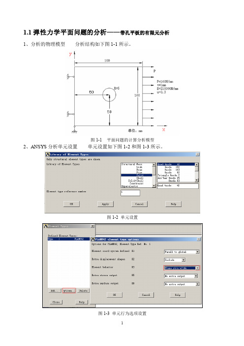
1.1弹性力学平面问题的分析——带孔平板的有限元分析1、分析的物理模型分析结构如下图1-1所示。
图1-1 平面问题的计算分析模型2、ANSYS分析单元设置单元设置如下图1-2和图1-3所示。
图1-2 单元设置图1-3 单元行为选项设置3、实常数设置设置平面问题的厚度为1,过程如下图1-4所示。
图1-4 实常数设置4、材料属性设置材料的弹性模量和泊淞比设定如下图1-5所示。
图1-5 材料模型5、几何建模先创建一个矩形如下图1-6所示,然后再创建一个圆如图1-7所示。
图1-6 矩形创建图1-7 创建圆进行布尔运算,先选取大的矩形,然后再选取小圆,之后完成布尔减运算,其过程如下图1-8所示。
选取矩形选取小圆运算后结果图1-8 执行布尔减运算6、网格划分按如下图1-9所示完成单元尺寸设置,设置每个边划分4个单元。
之后,按图1-10所示完成单元划分。
图1-9 单元尺寸设置图1-10 单元划分7、模型施加约束和外载约束施加:先施加X方向固定约束如图1-11所示,再施加Y向位移约束如图1-12所示。
图1-11 施加X方向位移约束图1-12 施加Y方向位移约束施加外载图1-13 施加外载荷图1-14 求解8、结果后处理查看受力后工件所受X方向应力和等效应力分布情况。
图1-15 后处理节点结果应力提取图1-16 X方向应力Mpa图1-17 米塞斯等效应力Mpa1.2弹性力学平面问题的分析——无限长厚壁圆筒问题描述:一无限长厚壁圆筒,如图1所示,内外壁分别承受压力p1=p2=10N/mm2。
受载前R1=100mm,R2=150mm,E=210Gpa,μ=0.3 。
取横截面八分之一进行计算,支撑条件及网格划分如下图2所示。
求圆筒内外半径的变化量及节点8处的支撑力大小及方向,给出节点位移云图和等效应力云图。
图1 图2此问题是弹性力学中的平面应变问题。
一、选择图形界面方式ANSYS main menu>preferences>structural可以不选择图形界面方式。
ANSYS教程

ANSYS教程第 1 章前言1.1 ANSYS简介ANSYS是一种广泛的商业套装工程分析软件。
所谓工程分析软件,主要是在机械结构系统受到外力负载所出现的反应,例如应力、位移、温度等,根据该反应可知道机械结构系统受到外力负载后的状态,进而判断是否符合设计要求。
一般机械结构系统的几何结构相当复杂,受的负载也相当多,理论分析往往无法进行。
想要解答,必须先简化结构,采用数值模拟方法分析。
由于计算机行业的发展,相应的软件也应运而生,ANSYS软件在工程上应用相当广泛,在机械、电机、土木、电子及航空等领域的使用,都能达到某种程度的可信度,颇获各界好评。
使用该软件,能够降低设计成本,缩短设计时间。
到80年代初期,国际上较大型的面向工程的有限元通用软件主要有:ANSYS, NASTRAN, ASKA, ADINA, SAP等。
以ANSYS为代表的工程数值模拟软件,是一个多用途的有限元法分析软件,它从1971年的2.0版本与今天的5.7版本已有很大的不同,起初它仅提供结构线性分析和热分析,现在可用来求结构、流体、电力、电磁场及碰撞等问题的解答。
它包含了前置处理、解题程序以及后置处理,将有限元分析、计算机图形学和优化技术相结合,已成为现代工程学问题必不可少的有力工具。
1.2 ANSYS软件主要功能ANSYS软件是融结构、热、流体、电磁、声学于一体的大型通用有限元软件,可广泛的用于核工业、铁道、石油化工、航空航天、机械制造、能源、汽车交通、国防军工、电子、土木工程、生物医学、水利、日用家电等一般工业及科学研究。
该软件提供了不断改进的功能清单,具体包括:结构高度非线性分析、电磁分析、计算流体力学分析、设计优化、接触分析、自适应网格划分及利用ANSYS参数设计语言扩展宏命令功能。
1.3 本教材内容•讲述如何利用ANSYS进行静力或稳态分析。
•面向的读者:针对不熟悉ANSYS实际应用的新用户或不常使用ANSYS 的用户。
讲授基本内容:•ANSYS功能,ANSYS基本术语和ANSYS图形用户界面。
ANSYS教程(非常有用)

第一章ANSYS的安装和配置ANSYS程序包括两张光盘:一张是ANSYS经典产品安装盘,另一张是ANSYSWorkbench产品安装盘。
本章以ANSYS10.0为例介绍ANSYS的安装、配置、启动及ANSYS的相关知识。
第一节ANSYS的安装一、安装ANSYS对系统的要求安装ANSYS对计算机系统的要求如下。
1.硬件要求①内存至少256M;②采用显存不少于32M的显卡,分辨率至少为1024x768,色彩为真彩色32位:③硬盘剩余空间至少2G;④安装网卡,设置好TCP/IP协议,并且TCP/IP协议绑定到此网卡上。
注意在TCP/1P协议中要设定计算机的hostname。
2.软件系统要求操作系统为Windows2000或WindowsXP以上。
二、安装ANSYS前的准备工作1.拷贝文件先将安装光盘中MAGNITUDE文件夹拷入计算机中,如D:LMAGNITUDE,用Windows的记事本打开D:~IAGNITUDE文件夹中的ansys.dat文件,该文件的第一行内容为"SERVERhostOOOOO(30000001055”,把host改为你的计算机名,如1wm是我的主机名,则host改为Ivan。
执行命令所有程序>附件,命令提示符进入DOS状态,键入1PCONFIG/ALL回车,所显示的physicaladdress即为网卡号,本例中计算机网卡的physicaladdress为000c6e10c8531055,则ansys.dat 文件的第一行内容修改为“SERVERlwm000c6e10c8531055”,以原文件名存盘退出。
2.生成许可文件运行D:\MAGNITUDE文件夹中的keygen.bat文件,生成license.dat,该文件就是ANSYS的许可文件,将它存放在指定目录下永久保存,本例中存放在D:LMAGNITUDE文件夹中。
三、安装ANSYS①将ANSYS的安装光盘放入光驱中,出现如图1-1的画面,选择Install ANSYS 10.0开始安装AHSYS10.0。
ANSYS基本使用方法
ANSYS基本使用方法
(1)启动ANSYS软件:
打开计算机,输入“ANSYS”的关键字,可以看到ANSYS的桌面图标,然后点击进入ANSYS环境。
(2)创建模型:
在ANSYS中,我们可以使用图形用户界面(GUI)来创建结构模型。
我们可以在程序中使用多种几何图像来构建模型,包括轴对称、柱面、集
成体等。
我们还可以从其他应用程序导入CAD模型,以加快模型构建过程。
(3)定义材料特性:
在定义模型之后,我们需要定义应用与模型的材料特性,如弹性模量、泊松比、强度等。
我们可以使用内置的材料特性定义,也可以导入独立的
材料特性定义文件,以考虑其他材料的特性。
(4)确定边界条件:
接下来,我们需要为模型定义应用的边界条件。
这些条件可以从结构
物理学的角度确定,根据模型的要求,我们可以为模型定义不同类型的边
界条件,包括不变位移,可变位移,约束力等。
(5)定义加载和仿真:
在定义完结构的边界条件之后,我们需要定义和实施不同类型的结构
加载和仿真。
- 1、下载文档前请自行甄别文档内容的完整性,平台不提供额外的编辑、内容补充、找答案等附加服务。
- 2、"仅部分预览"的文档,不可在线预览部分如存在完整性等问题,可反馈申请退款(可完整预览的文档不适用该条件!)。
- 3、如文档侵犯您的权益,请联系客服反馈,我们会尽快为您处理(人工客服工作时间:9:00-18:30)。
Mouse Functions
MODEL ORIENTATION FUNCTIONS
Drag left Drage middle Drag right – up/down Drag right – left/ right
Rotate display in 3D Translate model and global coords Zoom-in/ zoom-out Rotate moห้องสมุดไป่ตู้el in 2D plane of the screen
Introduction to Icepak objects
Icepak Objects are entities used to build your model
Fan Type: Intake fan with characteristic curve
Grill Type
Plate Type: Inclined polygonal plate Heat Sink Type: Pin-fin heat sink
1 port view
4 port view
Check model
…Post processing icons
Radiation view factors Solver window Plane cut IsoSurf Point Surface probe Variation plot Summary Report
Project label: Name and solution version of the project loaded into Icepak Main menu: All Icepak functions can be accessed with pull down menus Model toolbar: Icons to - create objects, edit objects, alignment features Shortcuts toolbar: Icons for commonly used functions Graphic display area (GDA): Image of the model is displayed Messages window: Icepak “talks” to the user here through text messages, examples - current state of Icepak, mesh quality, some post process reports Current object geometry (COG): Geometric information of selected object Model tree: List of all objects that constitute the project model, libraries, settings for problem, solver and general options
Model Tree: Physical model branch
If the Model branch is closed, only the cabinet (CFD domain) is visible
If the Model branch is open but no object is selected, all objects are visible in grey
Global coordinate axes (Axes): Shows the orientation of the model in GDA
NOTE: Place the mouse on an icon for a bubble message description of the icon B-5
Cabinet: CFD domain
Block Type: Solid Hexagonal block
Package Type: PBGA
Examples of objects in a model. The Object Types are shown in bold. B-6
Model toolbar: Create objects
Icepak Interface
B-1
Topics
• Icepak graphic user interface
•
• • • • • •
Introduction to Icepak objects
Model toolbar Shortcuts toolbar Model tree Mouse functions Model orientation Interactive editing tools
B-2
Icepak GUI map
PROJECT LABEL Main Menu Shortcuts Toolbar
M O D E L T R E E
M O D E L T O O L B A R
GRAPHIC DISPLAY AREA
MESSAGES
OBJECT GEOMETRY
B-3
Icepak GUI
enclosures
plates
packages
materials
walls
blocks
To create a new object, click the corresponding object type icon
B-7
Model toolbar: Edit and align functions
Object face History plot Trials plot
Solution ID Transient settings
B-9
Model Tree: Introduction
The top section of the model tree contains configuration parameters • Problem definition • Solver settings • Options – graphics, units, etc. The mid-section contains • Default and user defined libraries • Access to groups – collection of objects put together as a unit • Postprocessed graphic objects • Solution monitor points The bottom section contains • Trash bin • The inactive bin • The physical model branch – containing all objects that make up the model The bottom section is described in the following pages. The other sections are covered later in more detail B-10
Match edges
•
To create a new object, click the corresponding object type icon
B-8
Shortcuts Toolbar
File icons …..
New project
Save Create image file
Undo
Redo
toggle for opening or closing a branch
B-11
Model Tree: Physical model branch …
If any object is selected (blue highlight), all objects are visible in default (or specified) colors. The selected object is drawn in bold lines. An assembly type object, like the “Power-Supply” in this example, is a collection of objects combined into a single compound object
• Icepak has two Object Types: Simple and Composite
•
Every Type has a unique icon in the upper half of Model Toolbar
Icepak object type icons
assemblies networks heat exch. wires openings grille • sources PCBs fans vol. res. heat sinks
Current object – blue highlight in tree; bold in display
Assembly sub-branches are expandable like the Model branch
When an assembly‟s component is selected, the assembly is visible in default object colors but the rest of the model is shown in gray
project label
main menu shortcuts toolbar
m o d e l
t o o l b a r
graphic display area
global coordinate axes
