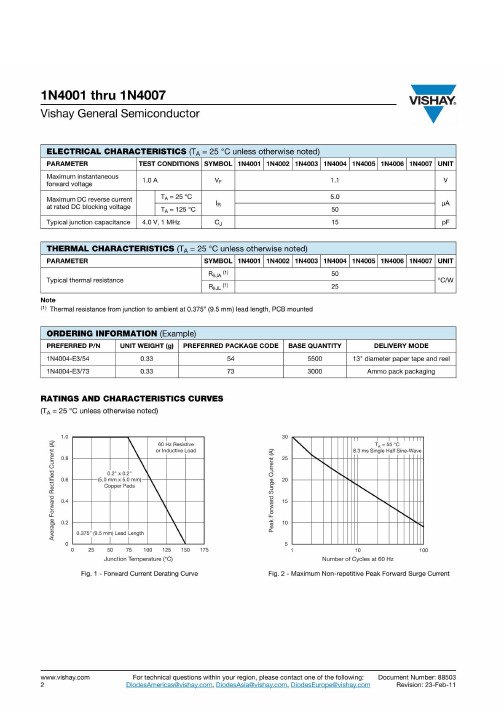
1N4001_NL中文资料
1n4001二极管的参数
1n4001二极管是一种常用的小功率整流二极管,它具有体积小,成本低,动态特性好,噪声小,反应快等优点,被广泛用于电源供电、功率放大、整流、稳压、抑制等电子电路中。
1n4001二极管的参数有:
1、最大正向电压:1N4001的最大正向电压为50V,最大反向电压为100V;
2、最大正向电流:1N4001的最大正向电流为1A;
3、最大正向功率:1N4001的最大正向功率为1W;
4、最大反向漏电流:1N4001的最大反向漏电流为100uA;
5、最大工作温度:1N4001的最大工作温度为125℃;
6、最小工作温度:1N4001的最小工作温度为-55℃;
7、正向恢复时间:1N4001的正向恢复时间为4μs;
8、反向恢复时间:1N4001的反向恢复时间为100μs;
9、正向结电容:1N4001的正向结电容为4pF。
1N4001二极管的参数非常典型,极大地满足了电子电路的要求,是一种非常受欢迎的二极管。
1N4001GP中文资料
100 50 Forward Current, IF [A]
10
Total Capacitance, CT [pF]
20 10 5
1
0.1
TJ = 25º C A Pulse Width = 200µS 300µ µ 1% 2% Duty Cycle
2 1 0.1 0.01 0.4
0.5 1 2 Reverse Voltage, VR [V]
元器件交易网
1N4001GP-1N4007GP
1N4001GP - 1N4007GP
Features • • • •
Low forward voltage drop. High surge current capability. High reliability. High current capability.Βιβλιοθήκη 302010
0
25
1
2
5 10 20 Number of Cycles at 60Hz
50
100
50 75 100 125 Ambient Temperature [ºC]
150
175
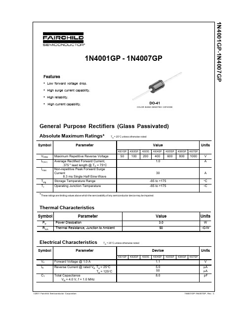
Figure 1. Non-Repetitive Surge Current
Figure 2. Forward Current Derating Curve
Preliminary
First Production
No Identification Needed
Full Production
Obsolete
Not In Production
This datasheet contains specifications on a product that has been discontinued by Fairchild semiconductor. The datasheet is printed for reference information only.
1N400X中文资料
1N4001/L - 1N4007/L
1.0A RECTIFIER
POWER SEMICONDUCTOR
Features
• • • • • Diffused Junction High Current Capability and Low Forward Voltage Drop Surge Overload Rating to 30A Peak Low Reverse Leakage Current Plastic Material: UL Flammability Classification Rating 94V-0
0.6
0.4
0.1
0.2
Tj = 25ºC PULSE WIDTH = 300µs 2% DUTY CYCLE
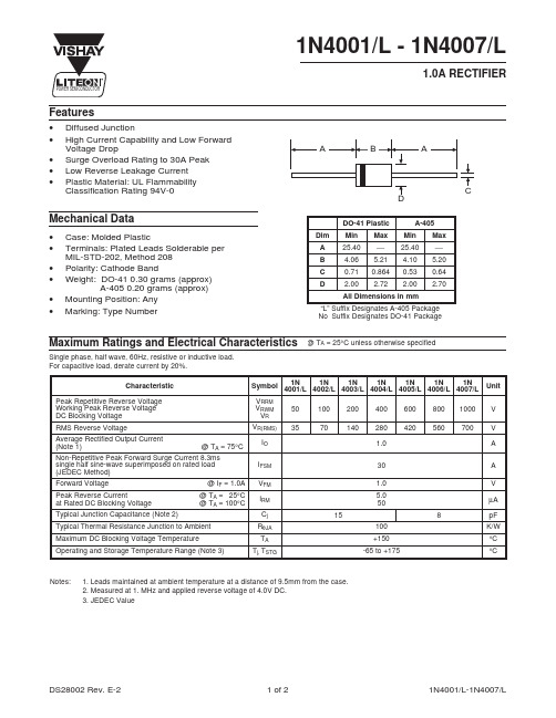
0 40 60 80 100 120 140 160 180 TA, AMBIENT TEMPERATURE (ºC) Fig. 1 Forward Current Derating Curve
40Βιβλιοθήκη 30Cj, CAPACITANCE (pF)
1N4001 - 1N4004
10
20
1N4005 - 1N4007
10
8.3ms Single half sine-wave JEDEC Method
0 1.0 10 100 NUMBER OF CYCLES AT 60 Hz Fig. 3 Max Non-Repetitive Peak Fwd Surge Current
1N 1N 1N 1N 1N 1N 1N Symbol 4001/L 4002/L 4003/L 4004/L 4005/L 4006/L 4007/L VRRM VRWM VR VR(RMS) IO IFSM VFM IRM Cj RθJA TA Tj, TSTG 15 100 +150 -65 to +175 50 35 100 70 200 140 400 280 1.0 30 1.0 5.0 50 8 600 420 800 560 1000 700
1N4001(Taiwan Semiconductor)中文数据手册「EasyDatasheet」
极性:颜色频带为负极
高温焊接防护证:260℃/ 10秒 /.375",设计(9.5mm)引线长度在5 lbs,(2.3千克)张力
重量:0.35克
尺寸以英寸(毫米) 标记图
1N400X G Y WW
=具体设备守则 =绿色复合 =年 =工作周
最大反向电流@额定VRT
满载最大反向电流,完整 周期平均.375"设计(9.5mm)铅Lenfth @T =75℃
典型结电容(注2)
=25 ℃ T =125℃
典型热阻
工作温度范围 存储温度范围
注1:与PW = 300微秒脉冲测试,1%占空比 注2:测量4.0V DC应用反向电压在1 MHz和
符
1N 1N 1N 1N 1N 1N 1N 4001 4002 4003 4004 4005 4006 4007
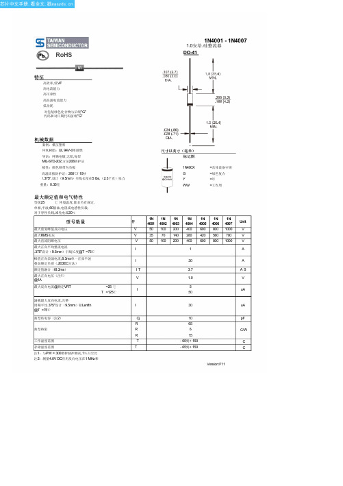
最大额定值和电气特性
等级25
℃ 环境温度,除非另有规定.
单相,半波,60赫兹,电阻或电感性负载.
对于容性负载,减免电流20%
型号数量
最大重复峰值反向电压
最大RMS电压
最大直流阻断电压 最大正向平均整流电流
.375"设计(9.5mm)引线长度@T =75℃
峰值正向浪涌电流,8.3ms单一正弦半波 叠加额定负荷(JEDEC方法) 额定值融合(t8.3ms) 最大正向电压(注1) @1A
图. 2最大非重复正向
浪涌电流 50
40
CURRENT(A)
30
8.3msSingle Half Wave JEDEC Method
20
PEAK FORWARD SURGE
1N4001数据手册_引脚图_参数
1N4000系列普通二极管型号大全

MA5091
9.1
5
500
BZX55C51
51
2.5
500
MA5100
10
5
500
BZX55C56
56
2.5
500
MA5110
11
5
500
BZX55C62
62
2.5
500
MA5120
12
5
500
BZX85C2V7
2.7
80
1300
MA5130
13
5
500
BZX85C3V0
3.0
80
1300
MA5150
MA3056
5.6
5
150
MA1082
8.2
5
400
MA3062
6.2
5
150
MA1091
9.1
5
400
MA3082
8.2
5
150
MA1100
10
5
400
MA3091
9.1
5
150
MA1110
11
5
400
MA3100
10
5
150
MA1114
11.4
10
400
MA3110
11
5
150
MA1120
12
5
5.6
5.0
45
10
DO-41
稳压二极管
008
1N4735
6.2
2.0
41
10
DO-41
稳压二极管
009
1N4736
6.8
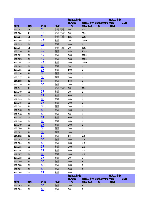
1N系列二极管手册
整流,
400
790m
整流,
400
500m
快速恢复, 用途
70
10m
极限工作电
最高工作频
压Vrwm 极限工作电 耗散功率Pw 率fm
null
(V)
流Im(A) (W)
(Hz)
普通用途, 60
30m
普通用途, 70
20m
普通用途, 60
30m
整流,
50
35
1N1183A Si
37
1N1183R,RA Si
外形
7
3 3
1
1
整流, 整流, 整流, 整流, 整流, 普通用途, 整流, 整流, 整流, 整流, 整流, 整流, 整流, 整流, 整流, 整流, 普通用途, 整流, 整流, 整流, 整流, 整流, 整流, 整流, 整流, 整流, 整流, 整流, 整流, 整流, 整流, 整流, 整流, 整流, 整流, 整流, 整流, 整流,
400
3
快速恢复, 400
3.3
快速恢复, 400
3.3
整流,
500
3
快速恢复, 500
1
整流,
600
3
快速恢复, 600
3.3
快速恢复, 600
3.3
普通用途, 70
50m
高压,
1.5K
300m
高压,
1.5K
300m
微波,混频,
12G
极限工作电
最高工作频
压Vrwm 极限工作电 耗散功率Pw 率fm
5
1N1198 Si
SP
1N1198A Si
5
1N1199 Si
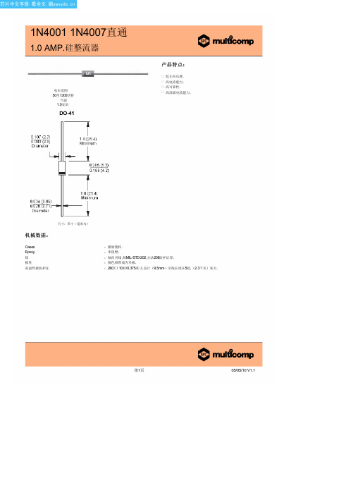
型号1N4004(MULTICOMP)中文数据手册「EasyDatasheet」
pF °C/W
°C
典型正向特性
安培
平均正向整流电流 环境温度(℃)
瞬时正向电流( A) 正向电压( V)
第2页
07/05/10 V1.1
芯片中文手册,看全文,戳
1N4001 1N4007直通
1.0 AMP.硅整流器
额 定 值 和 特 性 曲 线 ( 1N4001)
最大非重复正向浪涌电流
第3页
07/05/10 V1.1
第1页
05/05/10 V1.1
芯片中文手册,看全文,戳
1N4001 1N4007直通
1.0 AMP.硅整流器
最大额定值和电气特性:
评分在25°C环境温度,除非另有规定. 单相,半波,60赫兹,电阻或电感性负载. 对于容性负载,减免电流20%.
型号数量
最大经常峰值反向电压
最大RMS电压
典型结电容
峰值正向浪涌电流( A) 循环次数在 60Hz
典型反向特性
µ
瞬时反向电流( μA)
额定峰值反向电压百分比(%)
结电容( pF) 反向电压( V)
Disclaimer This data sheet and its contents (the "Information") belong to the Premier Farnell Group (the "Group") or are licensed to it. No licence is granted for the use of it other than for information purposes in connection with the products to which it relates. No licence of any intellectual property rights is granted. The Information is subject to change without notice and replaces all data sheets previously supplied. The Information supplied is believed to be accurate but the Group assumes no responsibility for its accuracy or completeness, any error in or omission from it or for any use made of it. Users of this data sheet should check for themselves the Information and the suitability of the products for their purpose and not make any assumptions based on information included or omitted. Liability for loss or damage resulting from any reliance on the Information or use of it (including liability resulting from negligence or where the Group was aware of the possibility of such loss or damage arising) is excluded. This will not operate to limit or restrict the Group's liability for death or personal injury resulting from its negligence. SPC Multicomp is the registered trademark of the Group. © Premier Farnell plc 2010.
1N系列常用整流二极管的主要参数
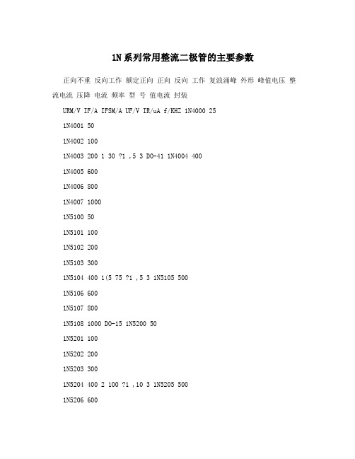
1N系列常用整流二极管的主要参数正向不重反向工作额定正向正向反向工作复浪涌峰外形峰值电压整流电流压降电流频率型号值电流封装URM/V IF/A IFSM/A UF/V IR/uA f/KHZ 1N4000 251N4001 501N4002 1001N4003 200 1 30 ?1 ,5 3 DO-41 1N4004 4001N4005 6001N4006 8001N4007 10001N5100 501N5101 1001N5102 2001N5103 3001N5104 400 1(5 75 ?1 ,5 3 1N5105 5001N5106 6001N5107 8001N5108 1000 DO-15 1N5200 501N5201 1001N5202 2001N5203 3001N5204 400 2 100 ?1 ,10 3 1N5205 5001N5206 6001N5207 8001N5208 10001N5400 501N5401 1001N5402 2001N5403 3001N5404 400 3 150 ?0.8 ,10 3 DO-271N5405 5001N5406 6001N5407 8001N5408 1000常用二极管参数:05Z6.2Y 硅稳压二极管 Vz=6~6.35V,Pzm=500mW,05Z7.5Y 硅稳压二极管 Vz=7.34~7.70V,Pzm=500mW, 05Z13X 硅稳压二极管Vz=12.4~13.1V,Pzm=500mW,05Z15Y 硅稳压二极管 Vz=14.4~15.15V,Pzm=500mW,05Z18Y 硅稳压二极管 Vz=17.55~18.45V,Pzm=500mW,稳压二极管参数大全常用稳压二极管参数代换型号稳定电压(V) 最大功电流型号国产稳压管日立稳耗(mW) (mA) 压管最小值最大值新型号旧型号 HZ4B2 500 3.8 4.0 5 2CW102 2CW21 4B2 HZ4C1 500 4.0 4.2 5 2CW102 2CW21 4C1HZ6 500 5.5 5.8 5 2CW103 2CW21A 6B1HZ6A 500 5.2 5.7 5 2CW103 2CW21A HZ6C3 500 6 6.4 5 2CW104 2CW21B 6C3 HZ7 500 6.9 7.2 5 2CW105 2CW21CHZ7A 500 6.3 6.9 5 2CW105 2CW21CHZ7B 500 6.7 7.3 5 2CW105 2CW21CHZ9A 500 7.7 8.5 5 2CW106 2CW21D HZ9CTA 500 8.9 9.7 5 2CW107 2CW21E HZ11 500 9.5 11.9 5 2CW109 2CW21GHZ12 500 11.6 14.3 5 2CW111 2CW21H HZ12B 500 12.4 13.4 5 2CW1112CW21H HZ12B2 500 12.6 13.1 5 2CW111 2CW21H 12B2 HZ18Y 500 16.5 18.5 52CW113 2CW21J HZ20-1 500 18.86 19.44 2 2CW114 2CW21KHZ27 500 27.2 28.6 2 2CW117 2CW21L 27-3 HZT33-02 400 31 33.5 52CW119 2CW21M RD2.0E(B) 500 1.88 2.12 20 2CW100 2CW21P 2B1 RD2.7E 400 2.5 2.93 20 2CW101 2CW21S RD3.9EL1 500 3.7 4 20 2CW102 2CW21 4B2RD5.6EN1 500 5.2 5.5 20 2CW103 2CW21A 6A1 RD5.6EN3 500 5.6 5.9 20 2CW104 2CW21B 6B2 RD5.6EL2 500 5.5 5.7 20 2CW103 2CW21A 6B1 RD6.2E(B) 500 5.88 6.6 20 2CW104 2CW21B RD7.5E(B) 500 7.0 7.9 20 2CW105 2CW21C RD10EN3 500 9.7 10.0 20 2CW108 2CW21F 11A2 RD11E(B) 500 10.1 11.8 15 2CW109 2CW21G RD12E 500 11.74 12.35 10 2CW110 2CW21H 12A1 RD12F 1000 11.19 11.77 202CW109 2CW21GRD13EN1 500 12 12.7 10 2CW110 2CW21H 12A3 RD15EL2 500 13.8 14.6 152CW112 2CW21J 12C3 RD24E 400 22 25 10 2CW116 2CW21H 24-1 RD24F 400 24 28 10 2CW117 2CW21L RD36EL1 500 32 34 15 2CW119 2CW21M 33-2 RD57E 500 48 54 10 1DS55-18 05Z5.1Y 500 4.94 5.20 2CW103 2CW21A 5C2 05Z5.6Z 500 5.615.91 2CW104 2CW21B 6B2 05Z6.2Y 500 5.96 6.27 41 2CW104 2CW21B 6C205Z7.5Y 500 7.07 7.45 34 2CW105 2CW21C 05Z7.5Z 500 7.3 7.7 34 2CW1052CW21C 7C2 05Z9.1Y 500 8.9 9.3 30 2CW107 2CW21E 9C1 05Z12 500 11.1312.35 21 2CW110 2CW21H 05Z12Z 500 12.0 12.6 20 2CW110 2CW21H 12A3 05Z13X500 12.11 12.75 19 2CW110 2CW21H 12A3 05Z13Z 500 13.5 14.1 18 2CW1112CW21H 12C2 05Z13Y 500 12.55 13.21 19 2CW111 2CW21H 12B2 05Z15 500 14.4 15.0 17 2CW112 2CW21J 15-2 05Z15Y 500 13.89 14.62 17 2CW111 2CW21H 12C3 05Z18 500 16.5 18.5 14 2CW113 2CW21J 05Z18Y 500 16.82 17.70 14 2CW1132CW21J 18-1 EQA01-11B 500 10.1 11.8 15 2CW109 2CW21G EQA01-12Z 500 11.2 13.1 15 2CW110 2CW21H EQA02-07B 400 6.66 7.01 20 2CW105 2CW21C 7A3EQA02-25A 500 24 25.5 2CW116 2CW21L 24-3 TVSQA106SB 500 5.88 6.6 202CW104 2CW21B TVSQA111SB 500 10.4 11.6 10 2CW109 2CW21G TVSQA111SE 500 11 11.5 10 2CW109 2CW21G 11C2 MA1130 1000 12.4 14.1 5 2CW111 2CW21HMA1330 500 31 35 25 2CW120 2CW21N M4030 500 2.9 3 5 2CW101 2CW21SuPC574JAG 200 31 35 25 2CW120 2CW21NRIMV 135 160 ZDW59快恢复二极管参数型号品牌电流电压时间极性 IN5817 GJ 1A 20V 10ns IN5819 GJ 1A 40V 10ns IN5819 MOT 1A 40V 10ns IN5822 MOT 3A 40V 10ns 21D-06 FUI 3A 60V10ns SBR360 GI 3A 60V 10ns C81-004 FUI 3A 40V 10ns 8TQ080 IR 8A 80V 10ns 单管 MBR1045 MOT 10A 45V 10ns 单管 MBR1545CT MOT 15A 45V 10ns 双管MBR1654 MOT 16A 45V 10ns 双管 16CTQ100 IR 16A 100V 10ns 双管 MBR2035CT MOT 20A 35V 10ns 双管 MBR2045CT MOT 20A 45V 10ns 双管 MBR2060CT MOT 20A 60V 10ns 双管 MBR20100CT IR 20A 100V 10ns 双管 025CTQ045 IR 25A 45V 10ns 双管 30CTQ045 IR 30A 45V 10ns 双管 C85-009* FUI 20A 90V 10ns 双管 D83-004* FUI 30A 40V 10ns 双管 D83-009* FUI 30A 90V 10ns 双管 MBR4060* IR40A 60V 10ns 双管 MBR30045 MOT 300A 45V 10ns MUR120 MOT 1A 200V 35ns MUR160 MOT 1A 600V 35ns MUR180 MOT 1A 800V 35ns MUR460 MOT 4A 600V 35nsBYV95 PHI 1.5A 1000V 250ns BYV27-50 PHI 2A 55V 25ns BYV927-100 PHI 2A 100V 25ns BYV927-300 PHI 2A 300V 25ns BYW76 PHI 3A 1000V 200ns BYT56G PHI 3A 600V 100ns BYT56M PHI 3A 1000V 100ns BYV26C PHI 1A 600V 30ns BYV26E PHI 1A 1000V 30ns FR607 GI 6A 1000V 200ns MUR8100 MOT 8A 1000V 35ns 单管HFA15TB60 IR 15A 600V 35ns 单管HFA25TB60 IR 25A 600V 35ns 单管MUR30100 HAR 30A 1000V 35ns 单管MUR30120 HAR 30A 1200V 35ns 单管MUR1620 PHI 16A 200V 35ns 双管MUR1620CT MOT 16A 200V 35ns 双管MUR1620P MOT 16A 200V 35ns 双管MUR1660CT MOT 16A 600V 35ns 双管HFA16TA600 IR 16A 600V 35ns 双管MUR3030 GI 30A 300V 35ns 双管MUR3040 MOT 30A 400V 35ns 双管MUR3060 MOT 30A 600V 35ns 双管HFA30TA600 IR 30A 600V 35ns 双管MUR20040 MOT 200A 400V 35ns 双管B92M-02 FUI 20A 200V 35ns 单管C92-02 FUI 20A 200V 35ns 双管D92M-02 FUI 30A 200V 35ns 双管D92M-03 FUI 30A 300V 35ns 双管DSE130-06 DSET 30A 600V 35ns 双管DSE160-06 DSET 60A 600V 35ns 双管稳压二极管常见稳压二极管的详细参数数据表代换型号稳定电压(V) 最大功耗电流型号国产稳压管日立稳压(mW) (mA) 管最小值最大值新型号旧型号 HZ4B2 500 3.8 4.0 5 2CW102 2CW21 4B2HZ4C1 500 4.0 4.2 5 2CW102 2CW21 4C1 HZ6 500 5.5 5.8 5 2CW103 2CW21A 6B1 HZ6A 500 5.2 5.7 5 2CW103 2CW21A HZ6C3 500 6 6.4 5 2CW104 2CW21B 6C3 HZ7 500 6.9 7.2 5 2CW105 2CW21C HZ7A 500 6.3 6.9 5 2CW105 2CW21C HZ7B 5006.77.3 5 2CW105 2CW21C HZ9A 500 7.78.5 5 2CW106 2CW21D HZ9CTA 500 8.99.7 5 2CW107 2CW21E HZ11 500 9.5 11.9 5 2CW109 2CW21G HZ12 500 11.6 14.3 5 2CW111 2CW21H HZ12B 500 12.4 13.4 5 2CW111 2CW21HHZ12B2 500 12.6 13.1 5 2CW111 2CW21H 12B2 HZ18Y 500 16.5 18.5 52CW113 2CW21J HZ20-1 500 18.86 19.44 2 2CW114 2CW21K HZ27 500 27.2 28.62 2CW117 2CW21L 27-3 HZT33-02 400 31 33.5 5 2CW119 2CW21M RD2.0E(B) 500 1.88 2.12 20 2CW100 2CW21P 2B1 RD2.7E 400 2.5 2.93 20 2CW101 2CW21SRD3.9EL1 500 3.7 4 20 2CW102 2CW21 4B2 RD5.6EN1 500 5.2 5.5 20 2CW1032CW21A 6A1 RD5.6EN3 500 5.6 5.9 20 2CW104 2CW21B 6B2 RD5.6EL2 500 5.55.7 20 2CW103 2CW21A 6B1 RD6.2E(B) 500 5.88 6.6 20 2CW104 2CW21BRD7.5E(B) 500 7.0 7.9 20 2CW105 2CW21C RD10EN3 500 9.7 10.0 20 2CW1082CW21F 11A2 RD11E(B) 500 10.1 11.8 15 2CW109 2CW21G RD12E 500 11.7412.35 10 2CW110 2CW21H 12A1 RD12F 1000 11.19 11.77 20 2CW109 2CW21GRD13EN1 500 12 12.7 10 2CW110 2CW21H 12A3 RD15EL2 500 13.8 14.6 152CW112 2CW21J 12C3 RD24E 400 22 25 10 2CW116 2CW21H 24-1 RD24F 400 24 28 10 2CW117 2CW21L RD36EL1 500 32 34 15 2CW119 2CW21M 33-2 RD57E 500 48 5410 1DS55-18 05Z5.1Y 500 4.94 5.20 2CW103 2CW21A 5C2 05Z5.6Z 500 5.615.91 2CW104 2CW21B 6B2 05Z6.2Y 500 5.96 6.27 41 2CW104 2CW21B 6C205Z7.5Y 500 7.07 7.45 34 2CW105 2CW21C 05Z7.5Z 500 7.3 7.7 34 2CW1052CW21C 7C2 05Z9.1Y 500 8.9 9.3 30 2CW107 2CW21E 9C1 05Z12 500 11.1312.35 21 2CW110 2CW21H 05Z12Z 500 12.0 12.6 20 2CW110 2CW21H 12A3 05Z13X 500 12.11 12.75 19 2CW110 2CW21H 12A3 05Z13Z 500 13.5 14.1 18 2CW1112CW21H 12C2 05Z13Y 500 12.55 13.21 19 2CW111 2CW21H 12B2 05Z15 500 14.4 15.0 17 2CW112 2CW21J 15-2 05Z15Y 500 13.89 14.62 17 2CW111 2CW21H 12C3 05Z18 500 16.5 18.5 14 2CW113 2CW21J 05Z18Y 500 16.82 17.70 14 2CW1132CW21J 18-1 EQA01-11B 500 10.1 11.8 15 2CW109 2CW21G EQA01-12Z 500 11.2 13.1 15 2CW110 2CW21HEQA02-07B 400 6.66 7.01 20 2CW105 2CW21C 7A3 EQA02-25A 500 24 25.52CW116 2CW21L 24-3 TVSQA106SB 500 5.88 6.6 20 2CW104 2CW21B TVSQA111SB 500 10.4 11.6 10 2CW109 2CW21G TVSQA111SE 500 11 11.5 10 2CW109 2CW21G 11C2 MA1130 1000 12.4 14.1 5 2CW111 2CW21H MA1330 500 31 35 25 2CW1202CW21N M4030 500 2.9 3 5 2CW101 2CW21S uPC574JAG 200 31 35 25 2CW1202CW21NRIMV 135 160 ZDW59最大耗散功最大工作型号额定电压(V) 可代换型号率(W) 电流(mA)1N708 0.25 5.6 40 BWA54、2CW28-5.6V 1N709 0.25 6.2 40 2CW55/B、BWA55/E 1N710 0.25 6.8 36 2CW55A、2CW105-6.8V2CW56A、2CW28-7.5V、1N711 0.25 7.5 30 2CW106-7.5V 1N712 0.25 8.2 30 2CW57/B、2CW106-8.2V 1N713 0.25 9.1 27 2CW58A/B、2CW74 1N714 0.25 10 25 2CW18、2CW59/A/B 1N715 0.25 11 20 2CW76、2DW12F.BS31-12 1N716 0.25 12 202CW61/A、2CW77/A 1N717 0.25 13 18 2CW62/A、2DW12G 1N718 0.25 15 162CW112-15V、2CW78/A 1N719 0.25 16 15 2CW63/A/B、2DW12H 1N720 0.25 18 13 2CW20B、2CW64/B、2CW64-18 1N721 0.25 20 12 2CW65-20、2DW12I、BWA65 1N722 0.25 22 11 2CW20C、2DW12J 1N723 0.25 24 10 WCW116、2DW13A 1N724 0.25 27 9 2CW20D、2CW68、BWA68/D 1N725 0.40 30 13 2CW119-30V 1N726 0.40 33 122CW120-33V 1N727 0.40 36 11 2CW120-36V 1N728 0.40 39 10 2CW121-39V 1N748 0.50 3.8,4.0 125 HZ4B21N752 0.50 5.2,5.7 80 HZ6A1N753 0.50 5.8,6.1 80 2CW1321N754 0.5 6.3,6.8 70 H27A1N755 0.50 7.1,7.3 65 HZ7.5EB1N757 0.50 8.9,9.3 52 HZ9C1N962 0.50 9.5,11 45 2CW137 1N963 0.50 11,11.5 40 2CW138、HZ12A-21N964 0.50 12,12.5 40 HZ12C-2、MA1130TA 1N969 0.50 21,22.5 20 RD245B1N4240A 1 10 100 2CW108-10V、2CW109、2DW5 1N4724A 1 12 76 2DW6A、2CW110-12V 1N4728 1 3.3 270 2CW101-3V3 1N4729 1 3.6 252 2CW101-3V6 1N4729A 1 3.6 252 2CW101-3V6 1N4730A 1 3.9 234 2CW102-3V9 1N4731 1 4.3 217 2CW102-4V3 1N4731A 1 4.3 217 2CW102-4V3 1N4732/A 1 4.7 193 2CW102-4V7 1N4733/A 1 5.1 179 2CW103-5V1 1N4734/A 1 5.6 162 2CW103-5V6 1N4735/A 1 6.2 1461W6V2、2CW104-6V2 1N4736/A 1 6.8 138 1W6V8、2CW104-6V8 1N4737/A 1 7.5 121 1W7V5、2CW105-7V5 1N4738/A 1 8.2 110 1W8V2、2CW106-8V2 1N4739/A 1 9.1 100 1W9V1、2CW107-9V1 1N4740/A 1 10 91 2CW286-10V、B563-10 1N4741/A 1 11 83 2CW109-11V、2DW6 1N4742/A 1 12 76 2CW110-12V、2DW6A 1N4743/A 1 13 69 2CW111-13V、2DW6B、BWC114D 1N4744/A 1 15 57 2CW112-15V、2DW6D1N4745/A 1 16 51 2CW112-16V、2DW6E 1N4746/A 1 18 50 2CW113-18V、1W18V1N4747/A 1 20 45 2CW114-20V、BWC115E 1N4748/A 1 22 41 2CW115-22V、1W22V 1N4749/A 1 24 38 2CW116-24V、1W24V 1N4750/A 1 27 34 2CW117-27V、1W27V1N4751/A 1 30 30 2CW118-30V、1W30V、2DW19F 1N4752/A 1 33 27 2CW119-33V、1W33V 1N4753 0.5 36 13 2CW120-36V、1/2W36V 1N4754 0.5 39 12 2CW121-39V、1/2W39V 1N4755 0.5 43 12 2CW122-43V、1/2W43V 1N4756 0.5 47 10 2CW122-47V、1/2W47V 1N4757 0.5 51 9 2CW123-51V、1/2W51V 1N4758 0.5 56 8 2CW124-56V、1/2W56V 1N4759 0.5 62 8 2CW124-62V、1/2W62V1N4760 0.5 68 7 2CW125-68V、1/2W68V 1N4761 0.5 75 6.7 2CW126-75V、1/2W75V 1N4762 0.5 82 6 2CW126-82V、1/2W82V 1N4763 0.5 91 5.6 2CW127-91V、1/2W91V 1N4764 0.5 100 5 2CW128-100V、1/2W100V 1N5226/A 0.5 3.3 138 2CW51-3V3、2CW5226 1N5227/A/B 0.5 3.6 126 2CW51-3V6、2CW5227 1N5228/A/B 0.5 3.9 115 2CW52-3V9、2CW5228 1N5229/A/B 0.5 4.3 106 2CW52-4V3、2CW5229 1N5230/A/B 0.5 4.7 97 2CW53-4V7、2CW5230 1N5231/A/B 0.5 5.1 89 2CW53-5V1、2CW5231 1N5232/A/B 0.5 5.6 81 2CW103-5.6、2CW5232 1N5233/A/B 0.5 6 76 2CW104-6V、2CW5233 1N5234/A/B 0.5 6.2 73 2CW104-6.2V、2CW52341N5235/A/B 0.5 6.8 67 2CW105-6.8V、2CW5235稳压值稳定电流稳压值稳定电流型号功率(mW) 型号功率(mW) (V) (MA) (V) (MA) MA1030 3 5 400 MA2180 18 20 1000 MA1033 3.3 5 400 MA2200 20 20 1000 MA1036 3.6 5 400 MA2220 22 10 1000 MA1039 3.9 5 400 MA2240 24 10 1000 MA1043 4.3 5 400 MA2270 27 5 1000 MA1047 4.7 5 400 MA2300 30 5 1000 MA1051 5.1 5 400 MA2330 33 5 1000 MA1056 5.6 5 400 MA2360 36 5 1000MA1062 6.2 5 400 MA3047 4.7 5 150 MA1068 6.8 5 400 MA3051 5.1 5 150MA1075 7.5 5 400 MA3056 5.6 5 150 MA1082 8.2 5 400 MA3062 6.2 5 150MA1091 9.1 5 400 MA3082 8.2 5 150 MA1100 10 5 400 MA3091 9.1 5 150MA1110 11 5 400 MA3100 10 5 150 MA1114 11.4 10 400 MA3110 11 5 150MA1120 12 5 400 MA3120 12 5 150 MA1130 13 5 400 MA3130 13 5 150 MA1140 14 5 400 MA3150 15 5 150 MA1150 15 5 400 MA3160 16 5 150 MA1160 16 5 400 MA3180 18 5 150 MA1180 18 5 400 MA3200 20 5 150MA1200 20 5 400 MA3220 22 5 150 MA1220 22 5 400 MA3240 24 5 150MA1240 24 5 400 MA3270 27 2 150 MA1270 27 2 400 MA3300 30 2 150 MA1300 30 2 400 MA3330 33 2 150 MA1330 33 2 400 MA3360 36 2 150 MA1360 36 2 400 MA4030 3 5 370 MA2051 5.1 40 1000 MA4033 3.3 5 370 MA2056 5.6 40 1000 MA4036 3.6 5 370 MA2062 6.2 40 1000 MA4039 3.9 5 370 MA2068 6.8 40 1000 MA4043 4.3 5 370 MA2075 7.5 40 1000 MA4047 4.7 5 370 MA2082 8.2 40 1000 MA4051 5.1 5 370 MA2091 9.1 40 1000 MA4056 5.6 5 370 MA2100 10 40 1000 MA4062 6.2 5 370 MA2110 11 5 1000 MA4068 6.8 5 370 MA2120 12 5 1000MA4075 7.5 5 370 MA2130 13 5 1000 MA4082 8.2 5 370 MA2150 15 5 1000MA4091 9.1 5 370 MA2160 16 5 1000 MA4100 10 5 370 MA4110 11 5 370BZX55C6V8 6.8 5 500 MA4120 12 5 370 BZX55C7V5 7.5 5 500 MA4130 13 5 370 BZX55C8V2 8.2 5 500 MA4140 14 5 370 BZX55C9V1 9.1 5 500 MA4150 15 5 370 BZX55C10 10 5 500 MA4160 16 5 370 BZX55C11 11 5 500 MA4180 18 5 370BZX55C12 12 5 500 MA4200 20 5 370 BZX55C13 13 5 500 MA4220 22 5 370BZX55C15 15 5 500 MA4240 24 5 370 BZX55C16 16 5 500 MA4270 27 2 370BZX55C18 18 5 500 MA4300 30 2 370 BZX55C20 20 5 500 MA4330 33 2 370BZX55C22 22 5 500 MA4360 36 2 370 BZX55C24 24 5 500 MA5047 4.7 5 500 BZX55C27 27 5 500 MA5051 5.1 5 500 BZX55C30 30 5 500 MA5056 5.6 5 500BZX55C33 33 5 500 MA5062 6.2 5 500 BZX55C36 36 5 500 MA5068 6.8 5 500 BZX55C39 39 5 500 MA5075 7.5 5 500 BZX55C43 43 2.5 500MA5082 8.2 5 500 BZX55C47 47 2.5 500 MA5091 9.1 5 500 BZX55C51 51 2.5 500 MA5100 10 5 500 BZX55C56 56 2.5 500 MA5110 11 5 500 BZX55C62 622.5 500 MA5120 12 5 500 BZX85C2V7 2.7 80 1300 MA5130 13 5 500 BZX85C3V03.0 80 1300 MA5150 15 5 500 BZX85C3V3 3.3 80 1300 MA5160 16 5 500BZX85C3V6 3.6 70 1300 MA5180 18 5 500 BZX85C3V9 3.9 60 1300 MA5200 20 5 500 BZX85C4V3 4.3 50 1300 MA5240 24 5 500 BZX85C4V7 4.7 45 1300BZX55C2V4 2.4 5 500 BZX85C5V1 5.1 45 1300 BZX55C2V7 2.7 5 500 BZX85C5V6 5.6 45 1300 BZX55C3V0 3.0 5 500 BZX85C6V2 6.2 35 1300 BZX55C3V3 3.3 5 500 BZX85C6V8 6.8 35 1300 BZX55C3V6 3.6 5 500 BZX85C7V5 7.5 35 1300 BZX55C3V9 3.9 5 500 BZX85C8V2 8.2 25 1300 BZX55C4V3 4.3 5 500 BZX85C9V1 9.1 25 1300 BZX55C4V7 4.7 5 500 BZX85C10 10 25 1300 BZX55C5V1 5.1 5 500 BZX85C11 11 20 1300 BZX55C5V6 5.6 5 500 BZX85C12 12 20 1300 BZX55C6V2 6.2 5 500 BZX85C13 13 20 1300 BZX85C15 15 15 1300 BZX79A9V1 9.1 5 400 BZX85C16 16 15 1300 BZX79A10 10 5 400 BZX85C18 18 15 1300 BZX79A11 11 5 400 BZX85C20 20 10 1300 BZX79A12 12 5 400 BZX85C22 22 10 1300 BZX79A13 13 5 400 BZX85C24 24 10 1300 BZX79A15 15 5 400 BZX85C27 27 8 1300BZX79A16 16 5 400 BZX85C30 30 8 1300 BZX79A18 18 5 400 BZX85C33 33 8 1300 BZX79A20 20 5 400 BZX85C36 36 8 1300 BZX79A22 22 5 400 BZX85C39 39 6 1300 BZX79A24 24 5 400 BZX85C43 43 6 1300 BZX79A27 27 2 400 BZX85C47 47 4 1300 BZX79A30 30 2 400 BZX85C51 51 4 1300 BZX79A33 33 2 400BZX85C56 56 4 1300 BZX79A36 36 2 400 BZX85C62 62 4 1300 BZX79A39 39 2400 BZX55C68 68 2.5 500 BZX79A43 43 2 400 BZX55C75 75 2.5 500 BZX79A47 47 2 400BZX55C82 82 2.5 500 BZX79A51 51 2 400 BZX55C91 91 1 500 BZX79A56 56 2 400 BZX55C100 100 1 500 BZX79A62 62 2 400 BZX55C110 110 1 500 BZX79A68 68 2 400 BZX55C120 120 1 500 BZX79A75 75 2 400 BZX55C130 130 1 500BZX79C2V4 2.4 5 500 BZX55C150 150 1 500 BZX79C2V7 2.7 5 500 BZX55C160 160 1 500 BZX79C3V0 3.0 5 500 BZX55C180 180 1 500 BZX79C3V3 3.3 5 500 BZX55C200 200 1 500 BZX79C3V6 3.6 5 500 BZX79A2V4 2.4 5 400 BZX79C3V9 3.9 5 500 BZX79A2V7 2.7 5 400 BZX79C4V3 4.3 5 500 BZX79A3V0 3.0 5 400 BZX79C4V7 4.7 5 500 BZX79A3V3 3.3 5 400 BZX79C5V1 5.1 5 500 BZX79A3V6 3.6 5 400 BZX79C5V6 5.6 5 500 BZX79A3V9 3.9 5 400 BZX79C6V2 6.2 5 500 BZX79A4V3 4.3 5 400 BZX79C6V8 6.8 5 500 BZX79A4V7 4.7 5 400 BZX79C7V5 7.5 5 500 BZX79A5V1 5.1 5 400 BZX79C8V2 8.2 5 500 BZX79A5V6 5.6 5 400 BZX79C9V1 9.1 5 500 BZX79A6V2 6.2 5 400 BZX79C10 10 5 500 BZX79A6V8 6.8 5 400 BZX79C11 11 5 500 BZX79A7V5 7.5 5 400 BZX79C12 12 5 500 BZX79A8V2 8.2 5 400 BZX79C13 13 5 500变容二极管。
安森美1N4001-D 数据表说明书
DATA SHEET Axial-Lead GlassPassivated StandardRecovery Rectifiers1N4001, 1N4002, 1N4003,1N4004, 1N4005, 1N4006,1N4007This data sheet provides information on subminiature size, axiallead mounted rectifiers for general−purpose low−power applications. Features•Shipped in Plastic Bags, 1000 per bag•Available Tape and Reeled, 5000 per reel, by adding a “RL” suffix to the part number•Available in Fan−Fold Packaging, 3000 per box, by adding a “FF”suffix to the part number•Pb−Free Packages are AvailableMechanical Characteristics•Case: Epoxy, Molded•Weight: 0.4 gram (approximately)•Finish: All External Surfaces Corrosion Resistant and Terminal Leads are Readily Solderable•Lead and Mounting Surface Temperature for Soldering Purposes: 260°C Max. for 10 Seconds, 1/16 in. from case •Polarity: Cathode Indicated by Polarity Band*For additional information on our Pb−Free strategy and soldering details, please download the onsemi Soldering and Mounting T echniques Reference Manual, SOLDERRM/D.CASE 59−10AXIAL LEADPLASTICLEAD MOUNTED RECTIFIERS50−1000 VOLTSDIFFUSED JUNCTIONMARKING DIAGRAMSee detailed ordering and shipping information on page 5 of this data sheet.ORDERING INFORMATIONA= Assembly Location1N400x= Device Numberx= 1, 2, 3, 4, 5, 6 or 7YY= YearWW= Work WeekG= Pb−Free Package(Note: Microdot may be in either location)MAXIMUM RATINGSRating Symbol1N40011N40021N40031N40041N40051N40061N4007Unit†Peak Repetitive Reverse Voltage Working Peak Reverse Voltage DC Blocking Voltage V RRMV RWMV R501002004006008001000V†Non−Repetitive Peak Reverse Voltage(halfwave, single phase, 60 Hz)V RSM6012024048072010001200V †RMS Reverse Voltage V R(RMS)3570140280420560700V†Average Rectified Forward Current(single phase, resistive load,60 Hz, T A = 75°C)I O 1.0A†Non−Repetitive Peak Surge Current(surge applied at rated load conditions)I FSM30 (for 1 cycle)AOperating and Storage Junction Temperature Range T JT stg−65 to +150°CStresses exceeding those listed in the Maximum Ratings table may damage the device. If any of these limits are exceeded, device functionality should not be assumed, damage may occur and reliability may be affected.†Indicates JEDEC Registered DataTHERMAL CHARACTERISTICSRating Symbol Max Unit Maximum Thermal Resistance, Junction−to−Ambient R q JA Note 1°C/W ELECTRICAL CHARACTERISTICS†Rating Symbol Typ Max Unit Maximum Instantaneous Forward Voltage Drop, (i F = 1.0 Amp, T J = 25°C)v F0.93 1.1V Maximum Full−Cycle Average Forward Voltage Drop, (I O = 1.0 Amp, T L = 75°C, 1 inch leads)V F(AV)−0.8VMaximum Reverse Current (rated DC voltage) (T J = 25°C)(T J = 100°C)I R0.051.01050m AMaximum Full−Cycle Average Reverse Current, (I O = 1.0 Amp, T L = 75°C, 1 inch leads)I R(AV)−30m A Product parametric performance is indicated in the Electrical Characteristics for the listed test conditions, unless otherwise noted. Product performance may not be indicated by the Electrical Characteristics if operated under different conditions.†Indicates JEDEC Registered DataV F , INSTANTANEOUS FORWARD VOLTAGE (V)Figure 1. Typical Forward Voltage Figure 2. Typical Reverse CurrentI F , F O R W A R D C U R R E N T (A )1.0E −V R , REVERSE VOLTAGE (V)Figure 3. Typical CapacitanceI R , R E V E R S E C U R R E N T (A )1.0E −1.0E −1.0E −1.0E −1.0E −V R , REVERSE VOLTAGE (V)C , C A P A C I T A N C E (p F )NOTE 1. − AMBIENT MOUNTING DATAORDERING INFORMATIONDevice Package Shipping†1N4001Axial Lead*1000 Units/Bag1000 Units/Bag1N4001G Axial Lead*(Pb−Free)1N4001RL Axial Lead*5000/T ape & Reel5000/T ape & Reel1N4001RLG Axial Lead*(Pb−Free)1N4002Axial Lead*1000 Units/Bag1000 Units/Bag1N4002G Axial Lead*(Pb−Free)1N4002RL Axial Lead*5000/T ape & Reel5000/T ape & Reel1N4002RLG Axial Lead*(Pb−Free)1N4003Axial Lead*1000 Units/Bag1000 Units/Bag1N4003G Axial Lead*(Pb−Free)1N4003RL Axial Lead*5000/T ape & Reel5000/T ape & Reel1N4003RLG Axial Lead*(Pb−Free)1N4004Axial Lead*1000 Units/Bag1000 Units/Bag1N4004G Axial Lead*(Pb−Free)1N4004RL Axial Lead*5000/T ape & Reel5000/T ape & Reel1N4004RLG Axial Lead*(Pb−Free)1N4005Axial Lead*1000 Units/Bag1000 Units/Bag1N4005G Axial Lead*(Pb−Free)1N4005RL Axial Lead*5000/T ape & Reel5000/T ape & Reel1N4005RLG Axial Lead*(Pb−Free)1N4006Axial Lead*1000 Units/Bag1000 Units/Bag1N4006G Axial Lead*(Pb−Free)3000 Units/Box1N4006FFG Axial Lead*(Pb−Free)1N4006RL Axial Lead*5000/T ape & Reel1N4006RLG Axial Lead*5000/T ape & Reel(Pb−Free)1N4007Axial Lead*1000 Units/Bag1000 Units/Bag1N4007G Axial Lead*(Pb−Free)3000 Units/Box1N4007FFG Axial Lead*(Pb−Free)1N4007RL Axial Lead*5000/T ape & Reel5000/T ape & Reel1N4007RLG Axial Lead*(Pb−Free)†For information on tape and reel specifications, including part orientation and tape sizes, please refer to our Tape and Reel Packaging Specifications Brochure, BRD8011/D.*This package is inherently Pb−Free.SCALE 1:1BDIM MIN MAX MIN MAX MILLIMETERSINCHES A 4.10 5.200.1610.205B 2.00 2.700.0790.106D 0.710.860.0280.034F −−− 1.27−−−0.050K25.40−−−1.000−−−NOTES:1.DIMENSIONING AND TOLERANCING PER ANSI Y14.5M, 1982.2.CONTROLLING DIMENSION: INCH.3.ALL RULES AND NOTES ASSOCIATED WITH JEDEC DO −41 OUTLINE SHALL APPLY4.POLARITY DENOTED BY CATHODE BAND.5.LEAD DIAMETER NOT CONTROLLED WITHIN F DIMENSION.AXIAL LEAD CASE 59−10ISSUE UDATE 15 FEB 2005GENERICMARKING DIAGRAM*xxx = Specific Device Code A = Assembly Location YY = YearWW= Work WeekSTYLE 1:PIN 1.CATHODE (POLARITY BAND)2.ANODESTYLE 2:NO POLARITYSTYLE 1STYLE 2*This information is generic. Please refer to device data sheet for actual part marking.Pb −Free indicator, “G” or microdot “ G ”,may or may not be present.MECHANICAL CASE OUTLINEPACKAGE DIMENSIONSON Semiconductor and are trademarks of Semiconductor Components Industries, LLC dba ON Semiconductor or its subsidiaries in the United States and/or other countries.ON Semiconductor reserves the right to make changes without further notice to any products herein. ON Semiconductor makes no warranty, representation or guarantee regarding the suitability of its products for any particular purpose, nor does ON Semiconductor assume any liability arising out of the application or use of any product or circuit, and specifically disclaims any and all liability, including without limitation special, consequential or incidental damages. ON Semiconductor does not convey any license under its patent rights nor thePUBLICATION ORDERING INFORMATIONTECHNICAL SUPPORTNorth American Technical Support:Voice Mail: 1 800−282−9855 Toll Free USA/Canada Phone: 011 421 33 790 2910LITERATURE FULFILLMENT :Email Requests to:*******************onsemi Website: Europe, Middle East and Africa Technical Support:Phone: 00421 33 790 2910For additional information, please contact your local Sales Representative。
1N4001 D Axial-Lead Glass Passivated Standard Reco
DATA SHEET Axial-Lead GlassPassivated StandardRecovery Rectifiers1N4001, 1N4002, 1N4003,1N4004, 1N4005, 1N4006,1N4007This data sheet provides information on subminiature size, axiallead mounted rectifiers for general−purpose low−power applications. Features•Shipped in Plastic Bags, 1000 per bag•Available Tape and Reeled, 5000 per reel, by adding a “RL” suffix to the part number•Available in Fan−Fold Packaging, 3000 per box, by adding a “FF”suffix to the part number•Pb−Free Packages are AvailableMechanical Characteristics•Case: Epoxy, Molded•Weight: 0.4 gram (approximately)•Finish: All External Surfaces Corrosion Resistant and Terminal Leads are Readily Solderable•Lead and Mounting Surface Temperature for Soldering Purposes: 260°C Max. for 10 Seconds, 1/16 in. from case •Polarity: Cathode Indicated by Polarity Band*For additional information on our Pb−Free strategy and soldering details, please download the onsemi Soldering and Mounting T echniques Reference Manual, SOLDERRM/D.CASE 59−10AXIAL LEADPLASTICLEAD MOUNTED RECTIFIERS50−1000 VOLTSDIFFUSED JUNCTIONMARKING DIAGRAMSee detailed ordering and shipping information on page 5 of this data sheet.ORDERING INFORMATIONA= Assembly Location1N400x= Device Numberx= 1, 2, 3, 4, 5, 6 or 7YY= YearWW= Work WeekG= Pb−Free Package(Note: Microdot may be in either location)MAXIMUM RATINGSRating Symbol1N40011N40021N40031N40041N40051N40061N4007Unit†Peak Repetitive Reverse Voltage Working Peak Reverse Voltage DC Blocking Voltage V RRMV RWMV R501002004006008001000V†Non−Repetitive Peak Reverse Voltage(halfwave, single phase, 60 Hz)V RSM6012024048072010001200V †RMS Reverse Voltage V R(RMS)3570140280420560700V†Average Rectified Forward Current(single phase, resistive load,60 Hz, T A = 75°C)I O 1.0A†Non−Repetitive Peak Surge Current(surge applied at rated load conditions)I FSM30 (for 1 cycle)AOperating and Storage Junction Temperature Range T JT stg−65 to +150°CStresses exceeding those listed in the Maximum Ratings table may damage the device. If any of these limits are exceeded, device functionality should not be assumed, damage may occur and reliability may be affected.†Indicates JEDEC Registered DataTHERMAL CHARACTERISTICSRating Symbol Max Unit Maximum Thermal Resistance, Junction−to−Ambient R q JA Note 1°C/W ELECTRICAL CHARACTERISTICS†Rating Symbol Typ Max Unit Maximum Instantaneous Forward Voltage Drop, (i F = 1.0 Amp, T J = 25°C)v F0.93 1.1V Maximum Full−Cycle Average Forward Voltage Drop, (I O = 1.0 Amp, T L = 75°C, 1 inch leads)V F(AV)−0.8VMaximum Reverse Current (rated DC voltage) (T J = 25°C)(T J = 100°C)I R0.051.01050m AMaximum Full−Cycle Average Reverse Current, (I O = 1.0 Amp, T L = 75°C, 1 inch leads)I R(AV)−30m A Product parametric performance is indicated in the Electrical Characteristics for the listed test conditions, unless otherwise noted. Product performance may not be indicated by the Electrical Characteristics if operated under different conditions.†Indicates JEDEC Registered DataV F , INSTANTANEOUS FORWARD VOLTAGE (V)Figure 1. Typical Forward Voltage Figure 2. Typical Reverse CurrentI F , F O R W A R D C U R R E N T (A )1.0E −V R , REVERSE VOLTAGE (V)Figure 3. Typical CapacitanceI R , R E V E R S E C U R R E N T (A )1.0E −1.0E −1.0E −1.0E −1.0E −V R , REVERSE VOLTAGE (V)C , C A P A C I T A N C E (p F )NOTE 1. − AMBIENT MOUNTING DATAORDERING INFORMATIONDevice Package Shipping†1N4001Axial Lead*1000 Units/Bag1000 Units/Bag1N4001G Axial Lead*(Pb−Free)1N4001RL Axial Lead*5000/T ape & Reel5000/T ape & Reel1N4001RLG Axial Lead*(Pb−Free)1N4002Axial Lead*1000 Units/Bag1000 Units/Bag1N4002G Axial Lead*(Pb−Free)1N4002RL Axial Lead*5000/T ape & Reel5000/T ape & Reel1N4002RLG Axial Lead*(Pb−Free)1N4003Axial Lead*1000 Units/Bag1000 Units/Bag1N4003G Axial Lead*(Pb−Free)1N4003RL Axial Lead*5000/T ape & Reel5000/T ape & Reel1N4003RLG Axial Lead*(Pb−Free)1N4004Axial Lead*1000 Units/Bag1000 Units/Bag1N4004G Axial Lead*(Pb−Free)1N4004RL Axial Lead*5000/T ape & Reel5000/T ape & Reel1N4004RLG Axial Lead*(Pb−Free)1N4005Axial Lead*1000 Units/Bag1000 Units/Bag1N4005G Axial Lead*(Pb−Free)1N4005RL Axial Lead*5000/T ape & Reel5000/T ape & Reel1N4005RLG Axial Lead*(Pb−Free)1N4006Axial Lead*1000 Units/Bag1000 Units/Bag1N4006G Axial Lead*(Pb−Free)3000 Units/Box1N4006FFG Axial Lead*(Pb−Free)1N4006RL Axial Lead*5000/T ape & Reel1N4006RLG Axial Lead*5000/T ape & Reel(Pb−Free)1N4007Axial Lead*1000 Units/Bag1000 Units/Bag1N4007G Axial Lead*(Pb−Free)3000 Units/Box1N4007FFG Axial Lead*(Pb−Free)1N4007RL Axial Lead*5000/T ape & Reel5000/T ape & Reel1N4007RLG Axial Lead*(Pb−Free)†For information on tape and reel specifications, including part orientation and tape sizes, please refer to our Tape and Reel Packaging Specifications Brochure, BRD8011/D.*This package is inherently Pb−Free.SCALE 1:1BDIM MIN MAX MIN MAX MILLIMETERSINCHES A 4.10 5.200.1610.205B 2.00 2.700.0790.106D 0.710.860.0280.034F −−− 1.27−−−0.050K25.40−−−1.000−−−NOTES:1.DIMENSIONING AND TOLERANCING PER ANSI Y14.5M, 1982.2.CONTROLLING DIMENSION: INCH.3.ALL RULES AND NOTES ASSOCIATED WITH JEDEC DO −41 OUTLINE SHALL APPLY4.POLARITY DENOTED BY CATHODE BAND.5.LEAD DIAMETER NOT CONTROLLED WITHIN F DIMENSION.AXIAL LEAD CASE 59−10ISSUE UDATE 15 FEB 2005GENERICMARKING DIAGRAM*xxx = Specific Device Code A = Assembly Location YY = YearWW= Work WeekSTYLE 1:PIN 1.CATHODE (POLARITY BAND)2.ANODESTYLE 2:NO POLARITYSTYLE 1STYLE 2*This information is generic. Please refer to device data sheet for actual part marking.Pb −Free indicator, “G” or microdot “ G ”,may or may not be present.MECHANICAL CASE OUTLINEPACKAGE DIMENSIONSON Semiconductor and are trademarks of Semiconductor Components Industries, LLC dba ON Semiconductor or its subsidiaries in the United States and/or other countries.ON Semiconductor reserves the right to make changes without further notice to any products herein. ON Semiconductor makes no warranty, representation or guarantee regarding the suitability of its products for any particular purpose, nor does ON Semiconductor assume any liability arising out of the application or use of any product or circuit, and specifically disclaims any and all liability, including without limitation special, consequential or incidental damages. ON Semiconductor does not convey any license under its patent rights nor theADDITIONAL INFORMATIONTECHNICAL PUBLICATIONS:Technical Library:/design/resources/technical−documentation onsemi Website: ONLINE SUPPORT: /supportFor additional information, please contact your local Sales Representative at /support/sales。
1N4002;1N4001;1N4007;1N4003;1N4006;中文规格书,Datasheet资料
© 2009 Fairchild Semiconductor Corporation 1N4001 - 1N4007 Rev. C21* These ratings are limiting values above which the serviceability of any semiconductor device may by impaired.Thermal CharacteristicsElectrical Characteristics T A = 25°C unless otherwise notedSymbolParameterValueUnits4001400240034004400540064007V RRM Peak Repetitive Reverse Voltage 501002004006008001000V I F(AV)Average Rectified Forward Current .375 " lead length @ T A = 75°C 1.0A I FSM Non-Repetitive Peak Forward Surge Current 8.3ms Single Half-Sine-Wave 30A I 2t Rating for Fusing ( t<8.3ms ) 3.7A 2sec T STG Storage Temperature Range -55 to +175°C T JOperating Junction Temperature-55 to +175°CSymbolParameter ValueUnitsP D Power Dissipation3.0W R θJAThermal Resistance, Junction to Ambient50°C/WSymbolParameterValueUnitsV F Forward Voltage @ 1.0A1.1V I rr Maximum Full Load Reverse Current, FullCycle T A = 75°C 30µA I R Reverse Current @ Rated V R T A = 25°C T A = 100°C 5.050µA µA C TTotal Capacitance V R = 4.0V, f = 1.0MHz15pF© 2009 Fairchild Semiconductor Corporation 1N4001 - 1N4007 Rev. C2 2Build it Now¥CorePLUS¥CorePOWER¥CROSSVOLT¥CTL™Current Transfer Logic™ EcoSPARK®EfficentMax™ EZSWITCH™*™*®Fairchild®Fairchild Semiconductor®FACT Quiet Series™ FACT®FAST®FastvCore¥FETBench¥FlashWriter®*FPS¥FRFET®Global Power Resource SMGreen FPS¥Green FPS¥ e-Series¥G max™GTO¥IntelliMAX¥ISOPLANAR¥MegaBuck™MICROCOUPLER¥MicroFET¥MicroPak¥MillerDrive™MotionMax™Motion-SPM™OPTOLOGIC®OPTOPLANAR®®PDP SPM™Power-SPM¥PowerXS™Programmable Active Droop¥QFET®QS¥Quiet Series¥RapidConfigure¥™Saving our world, 1mW/W/kW at a time™SmartMax™SMART START¥SPM®STEALTH™SuperFET¥SuperSOT¥-3SuperSOT¥-6SuperSOT¥-8SupreMOS™SyncFET™Sync-Lock™®*TinyBoost¥TinyBuck¥TinyLogic®TINYOPTO¥TinyPower¥TinyPWM¥TinyWire¥TriFault Detect¥TRUECURRENT¥*P SerDes¥UHC®Ultra FRFET¥UniFET¥VCX¥VisualMax¥XS™* Trademarks of System General Corporation, used under license by Fairchild Semiconductor.DISCLAIMERFAIRCHILD SEMICONDUCTOR RESERVES THE RIGHT TO MAKE CHANGES WITHOUT FURTHER NOTICE TO ANY PRODUCTS HEREIN TO IMPROVE RELIABILITY, FUNCTION, OR DESIGN. FAIRCHILD DOES NOT ASSUME ANY LIABILITY ARISING OUT OF THE APPLICATION OR USE OF ANY PRODUCT OR CIRCUIT DESCRIBED HEREIN; NEITHER DOES IT CONVEY ANY LICENSE UNDER ITS PATENT RIGHTS, NOR THE RIGHTS OF OTHERS. THESE SPECIFICATIONS DO NOT EXPAND THE TERMS OF FAIRCHILD’S WORLDWIDE TERMS AND CONDITIONS, SPECIFICALLY THE WARRANTY THEREIN, WHICH COVERS THESE PRODUCTS.LIFE SUPPORT POLICYFAIRCHILD’S PRODUCTS ARE NOT AUTHORIZED FOR USE AS CRITICAL COMPONENTS IN LIFE SUPPORT DEVICES OR SYSTEMS WITHOUT THE EXPRESS WRITTEN APPROVAL OF FAIRCHILD SEMICONDUCTOR CORPORATION.As used herein:1. Life support devices or systems are devices or systems which, (a) areintended for surgical implant into the body or (b) support or sustain life, and (c) whose failure to perform when properly used in accordance with instructions for use provided in the labeling, can be reasonably expected to result in a significant injury of the user. 2. A critical component in any component of a life support, device, orsystem whose failure to perform can be reasonably expected to cause the failure of the life support device or system, or to affect its safety or effectiveness.ANTI-COUNTERFEITING POLICYFairchild Semiconductor Corporation's Anti-Counterfeiting Policy. Fairchild's Anti-Counterfeiting Policy is also stated on our external website, , under Sales Support.Counterfeiting of semiconductor parts is a growing problem in the industry. All manufacturers of semiconductor products are experiencing counterfeiting of their parts.Customers who inadvertently purchase counterfeit parts experience many problems such as loss of brand reputation, substandard performance, failed applications, and increased cost of production and manufacturing delays. Fairchild is taking strong measures to protect ourselves and our customers from the proliferation ofcounterfeit parts. Fairchild strongly encourages customers to purchase Fairchild parts either directly from Fairchild or from Authorized Fairchild Distributors who are listed by country on our web page cited above. Products customers buy either from Fairchild directly or from Authorized Fairchild Distributors are genuine parts, have full traceability, meet Fairchild's quality standards for handling and storage and provide access to Fairchild's full range of up-to-date technical and product information.Fairchild and our Authorized Distributors will stand behind all warranties and will appropriately address any warranty issues that may arise. Fairchild will not provide any warranty coverage or other assistance for parts bought from Unauthorized Sources. Fairchild is committed to combat this global problem and encourage ourcustomers to do their part in stopping this practice by buying direct or from authorized distributors.© 2008 Fairchild Semiconductor Corporation 分销商库存信息:FAIRCHILD1N40021N40011N40071N40031N40061N40041N40051N4001GP1N4002GP 1N4004GP1N4003GP1N4005GP 1N4006GP1N4007GP。
1N4007中文资料_数据手册_参数
1N4007(MULTICOMP)元件中文手册「EasyDatasheet」
0.4
0.2
0 0 20 40 60 80 100 120 140
160 180
AMBIENT TEMPERATURE ( º C)
通用整流器
1N4001-1N4007
(持续)
正向特性
20 10
4 2 1
0.4 FORWARD CURRENT (A)
0.2
A) 100 µ
º
10
º REVER1SE CURRENT (
0.1
º
0.01 0 20 40 60 80 100 120 140 RATED PEAK REVERSE VOLTAGE (%)
参数
平均整流电流
.375"引线长度@ T
= 75°C
峰值正向浪涌电流
8.3毫秒单半正弦波
叠加额定负荷(JEDEC方法)
器件总功耗
减免上述25℃
热阻,结到环境
存储温度范围
工作结温
值 1.0
30
2.5 20 50 -55到+175 -55到+150
* These ratings are limiting values above which the serviceability of any semiconductor device may be impaired.
芯片中文手册,看全文,戳
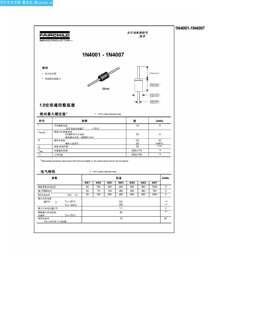
分立功率和信号 技术
1N4001-1N4007
1N4001 - 1N4007
特征
• 低正向压降. • 高浪涌电流能力.
DO-41
1.0安培通用整流器
绝对最大额定值*
T = 25°C unless otherwise noted
1N4007RLG;1N4002RLG;1N4004RLG;1N4005RLG;1N4003RLG;中文规格书,Datasheet资料
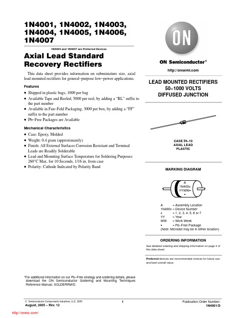
1N4001, 1N4002, 1N4003,1N4004, 1N4005, 1N4006,1N40071N4004 and 1N4007 are Preferred DevicesAxial Lead Standard Recovery RectifiersThis data sheet provides information on subminiature size, axial lead mounted rectifiers for general−purpose low−power applications. Features•Shipped in plastic bags, 1000 per bag•Available Tape and Reeled, 5000 per reel, by adding a “RL” suffix to the part number•Available in Fan−Fold Packaging, 3000 per box, by adding a “FF”suffix to the part number•Pb−Free Packages are AvailableMechanical Characteristics•Case: Epoxy, Molded•Weight: 0.4 gram (approximately)•Finish: All External Surfaces Corrosion Resistant and Terminal Leads are Readily Solderable•Lead and Mounting Surface Temperature for Soldering Purposes: 260°C Max. for 10 Seconds, 1/16 in. from case •Polarity: Cathode Indicated by Polarity Band*For additional information on our Pb−Free strategy and soldering details, please download the ON Semiconductor Soldering and Mounting Techniques Reference Manual, SOLDERRM/D.CASE 59−10AXIAL LEADPLASTICLEAD MOUNTED RECTIFIERS50−1000 VOLTSDIFFUSED JUNCTIONPreferred devices are recommended choices for future use and best overall value.MARKING DIAGRAMSee detailed ordering and shipping information on page 4 of this data sheet.ORDERING INFORMATIONA= Assembly Location1N400x= Device Numberx= 1, 2, 3, 4, 5, 6 or 7YY= YearWW= Work WeekG= Pb−Free Package(Note: Microdot may be in either location)A1N400xYYWW GGMAXIMUM RATINGSRating Symbol1N40011N40021N40031N40041N40051N40061N4007Unit†Peak Repetitive Reverse Voltage Working Peak Reverse Voltage DC Blocking Voltage V RRMV RWMV R501002004006008001000V†Non−Repetitive Peak Reverse Voltage(halfwave, single phase, 60 Hz)V RSM6012024048072010001200V †RMS Reverse Voltage V R(RMS)3570140280420560700V†Average Rectified Forward Current(single phase, resistive load,60 Hz, T A = 75°C)I O 1.0A†Non−Repetitive Peak Surge Current(surge applied at rated load conditions)I FSM30 (for 1 cycle)AOperating and Storage Junction Temperature RangeT JT stg−65 to +175°CMaximum ratings are those values beyond which device damage can occur. Maximum ratings applied to the device are individual stress limit values (not normal operating conditions) and are not valid simultaneously. If these limits are exceeded, device functional operation is not implied, damage may occur and reliability may be affected.ELECTRICAL CHARACTERISTICS†Rating Symbol Typ Max Unit Maximum Instantaneous Forward Voltage Drop, (i F = 1.0 Amp, T J = 25°C)v F0.93 1.1V Maximum Full−Cycle Average Forward Voltage Drop, (I O = 1.0 Amp, T L = 75°C, 1 inch leads)V F(AV)−0.8VMaximum Reverse Current (rated DC voltage) (T J = 25°C)(T J = 100°C)I R0.051.01050m AMaximum Full−Cycle Average Reverse Current, (I O = 1.0 Amp, T L = 75°C, 1 inch leads)I R(AV)−30m A †Indicates JEDEC Registered Data10.110I F , F O R W A R D C U R R E N T (A )Figure 3. Typical CapacitanceV R , REVERSE VOLTAGE (V)1N4001Axial Lead*1000 Units/Bag1N4001G Axial Lead*1000 Units/Bag(Pb−Free)1N4001FF Axial Lead*3000 Units/Box3000 Units/Box1N4001FFG Axial Lead*(Pb−Free)1N4001RL Axial Lead*5000/T ape & Reel5000/T ape & Reel1N4001RLG Axial Lead*(Pb−Free)1N4002Axial Lead*1000 Units/Bag1000 Units/Bag1N4002G Axial Lead*(Pb−Free)1N4002FF Axial Lead*3000 Units/Box3000 Units/Box1N4002FFG Axial Lead*(Pb−Free)1N4002RL Axial Lead*5000/T ape & Reel5000/T ape & Reel1N4002RLG Axial Lead*(Pb−Free)1N4003Axial Lead*1000 Units/Bag1N4003G Axial Lead*1000 Units/Bag(Pb−Free)1N4003FF Axial Lead*3000 Units/Box3000 Units/Box1N4003FFG Axial Lead*(Pb−Free)1N4003RL Axial Lead*5000/T ape & Reel5000/T ape & Reel1N4003RLG Axial Lead*(Pb−Free)1N4004Axial Lead*1000 Units/Bag1000 Units/Bag1N4004G Axial Lead*(Pb−Free)1N4004FF Axial Lead*3000 Units/Box3000 Units/Box1N4004FFG Axial Lead*(Pb−Free)1N4004RL Axial Lead*5000/T ape & Reel5000/T ape & Reel1N4004RLG Axial Lead*(Pb−Free)1N4005Axial Lead*1000 Units/Bag1N4005G Axial Lead*1000 Units/Bag(Pb−Free)1N4005FF Axial Lead*3000 Units/Box3000 Units/Box1N4005FFG Axial Lead*(Pb−Free)1N4005RL Axial Lead*5000/T ape & Reel5000/T ape & Reel1N4005RLG Axial Lead*(Pb−Free)†For information on tape and reel specifications, including part orientation and tape sizes, please refer to our Tape and Reel Packaging Specifications Brochure, BRD8011/D.*This package is inherently Pb−Free.1N4006Axial Lead*1000 Units/Bag1000 Units/Bag1N4006G Axial Lead*(Pb−Free)1N4006FF Axial Lead*3000 Units/Box3000 Units/Box1N4006FFG Axial Lead*(Pb−Free)1N4006RL Axial Lead*5000/T ape & Reel1N4006RLG Axial Lead*5000/T ape & Reel(Pb−Free)1N4007Axial Lead*1000 Units/Bag1000 Units/Bag1N4007G Axial Lead*(Pb−Free)1N4007FF Axial Lead*3000 Units/Box3000 Units/Box1N4007FFG Axial Lead*(Pb−Free)1N4007RL Axial Lead*5000/T ape & Reel1N4007RLG Axial Lead*5000/T ape & Reel(Pb−Free)†For information on tape and reel specifications, including part orientation and tape sizes, please refer to our Tape and Reel Packaging Specifications Brochure, BRD8011/D.*This package is inherently Pb−Free.PACKAGE DIMENSIONSAXIAL LEAD CASE 59−10ISSUE UDIM MIN MAX MIN MAX MILLIMETERSINCHES A 4.10 5.200.1610.205B 2.00 2.700.0790.106D 0.710.860.0280.034F −−− 1.27−−−0.050K25.40−−−1.000−−−NOTES:1.DIMENSIONING AND TOLERANCING PER ANSI Y14.5M, 1982.2.CONTROLLING DIMENSION: INCH.3.ALL RULES AND NOTES ASSOCIATED WITH JEDEC DO−41 OUTLINE SHALL APPLY4.POLARITY DENOTED BY CATHODE BAND.5.LEAD DIAMETER NOT CONTROLLED WITHIN F DIMENSION.ON Semiconductor and are registered trademarks of Semiconductor Components Industries, LLC (SCILLC). SCILLC reserves the right to make changes without further noticeto any products herein. SCILLC makes no warranty, representation or guarantee regarding the suitability of its products for any particular purpose, nor does SCILLC assume any liability arising out of the application or use of any product or circuit, and specifically disclaims any and all liability, including without limitation special, consequential or incidental damages.“Typical” parameters which may be provided in SCILLC data sheets and/or specifications can and do vary in different applications and actual performance may vary over time. All operating parameters, including “Typicals” must be validated for each customer application by customer’s technical experts. SCILLC does not convey any license under its patent rights nor the rights of others. SCILLC products are not designed, intended, or authorized for use as components in systems intended for surgical implant into the body, or other applications intended to support or sustain life, or for any other application in which the failure of the SCILLC product could create a situation where personal injury or death may occur. Should Buyer purchase or use SCILLC products for any such unintended or unauthorized application, Buyer shall indemnify and hold SCILLC and its officers, employees, subsidiaries, affiliates,and distributors harmless against all claims, costs, damages, and expenses, and reasonable attorney fees arising out of, directly or indirectly, any claim of personal injury or death associated with such unintended or unauthorized use, even if such claim alleges that SCILLC was negligent regarding the design or manufacture of the part. SCILLC is an Equal Opportunity/Affirmative Action Employer. This literature is subject to all applicable copyright laws and is not for resale in any manner.PUBLICATION ORDERING INFORMATION分销商库存信息:ONSEMI1N4007RLG1N4002RLG1N4004RLG 1N4005RLG1N4003RLG1N4001RLG 1N4004G1N4007G1N4001G1N4002G1N4003G1N4006G1N4005G1N4001RL1N4002RL 1N4003RL1N4004RL1N4005RL 1N4006RL1N4006RLG1N4007RL。
1N4001G-T3中文资料
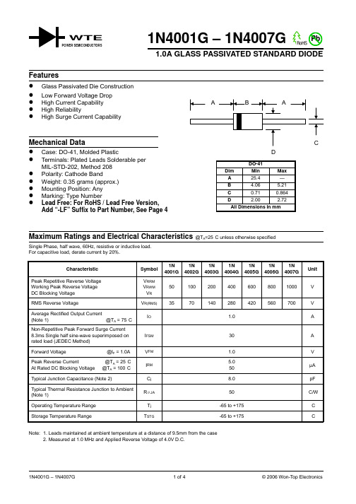
1N4001G – 1N4007G1.0A GLASS PASSIVATED STANDARD DIODESingle Phase, half wave, 60Hz, resistive or inductive load.For capacitive load, derate current by 20%.CharacteristicSymbol 1N 4001G 1N 4002G 1N 4003G 1N 4004G 1N 4005G 1N 4006G 1N 4007G UnitPeak Repetitive Reverse Voltage Working Peak Reverse Voltage DC Blocking Voltage V RRMV RWM V R 501002004006008001000V RMS Reverse VoltageV R(RMS)3570140280420560700V Average Rectified Output Current(Note 1) @T A = 75°C I O1.0ANon-Repetitive Peak Forward Surge Current 8.3ms Single half sine-wave superimposed on rated load (JEDEC Method)I FSM 30A Forward Voltage @I F = 1.0A V FM 1.0V Peak Reverse Current @T A = 25°C At Rated DC Blocking Voltage @T A = 100°C I RM 5.050µA Typical Junction Capacitance (Note 2)C j 8.0pF Typical Thermal Resistance Junction to Ambient (Note 1)R JA 50°C/W Operating Temperature Range T j -65 to +175°C Storage Temperature RangeT STG-65 to +175°CNote: 1. Leads maintained at ambient temperature at a distance of 9.5mm from the case2. Measured at 1.0 MHz and Applied Reverse Voltage of 4.0V D.C.WTE40608010012014016018000.20.40.60.81.0I ,A V E R A G E F O R W A R D R E C T I F I E D C U R R E N T (A )(A V )T ,AMBIENT TEMPERATURE (ºC)Fig.1Forward Current Derating CurveA C ,C A P A C I T A N C E (p F )j V ,REVERSE VOLTAGE (V)Fig.4T ypical Junction CapacitanceR 1.0101001.0101001.010100I ,P E A K F O R W A R D S U R G E C U R R E N T (A )F S M NUMBER OF CYCLES AT 60HzFig.3Max Non-Repetitive Peak Fwd Surge Current403020010500.60.8 1.0 1.2 1.4 1.60.010.11.0I ,I N S T A N T A N E O U S F O R W A R D C U R R E N T (A )F V ,INSTANTANEOUS FORWARD VOLTAGE (V)Fig.2Typical Forward CharacteristicsF 10MARKING INFORMATION TAPING SPECIFICATIONS6mmORDERING INFORMATIONProduct No.Package TypeShipping Quantity1N4001G-T3DO-415000/Tape & Reel 1N4001G-TB DO-415000/Tape & Box 1N4001G DO-411000 Units/Box 1N4002G-T3DO-415000/Tape & Reel 1N4002G-TB DO-415000/Tape & Box 1N4002G DO-411000 Units/Box 1N4003G-T3DO-415000/Tape & Reel 1N4003G-TB DO-415000/Tape & Box 1N4003G DO-411000 Units/Box 1N4004G-T3DO-415000/Tape & Reel 1N4004G-TB DO-415000/Tape & Box 1N4004G DO-411000 Units/Box 1N4005G-T3DO-415000/Tape & Reel 1N4005G-TB DO-415000/Tape & Box 1N4005G DO-411000 Units/Box 1N4006G-T3DO-415000/Tape & Reel 1N4006G-TB DO-415000/Tape & Box 1N4006G DO-411000 Units/Box 1N4007G-T3DO-415000/Tape & Reel 1N4007G-TB DO-415000/Tape & Box 1N4007GDO-411000 Units/Box1. Products listed in bold are WTE Preferred devices.2. Shipping quantity given is for minimum packing quantity only. For minimum order quantity, please consult the Sales Department.3.To order RoHS / Lead Free version (with Lead Free finish), add “-LF” suffix to part number above. For example, 1N4001G-TB-LF .Won-Top Electronics Co., Ltd (WTE) has checked all information carefully and believes it to be correct and accurate. However, WTE cannot assume any responsibility for inaccuracies. Furthermore, this information does not give the purchaser of semiconductor devices any license under patent rights to manufacturer. WTE reserves the right to change any or all information herein without further notice.WARNING : DO NOT USE IN LIFE SUPPORT EQUIPMENT. WTE power semiconductor products are not authorized for use as critical components in life support devices or systems without the express written approval.We power your everyday.Won-Top Electronics Co., Ltd.No. 44 Yu Kang North 3rd Road, Chine Chen Dist., Kaohsiung, Taiwan Phone: 886-7-822-5408 or 886-7-822-5410Fax: 886-7-822-5417Email: sales@Internet: 。
- 1、下载文档前请自行甄别文档内容的完整性,平台不提供额外的编辑、内容补充、找答案等附加服务。
- 2、"仅部分预览"的文档,不可在线预览部分如存在完整性等问题,可反馈申请退款(可完整预览的文档不适用该条件!)。
- 3、如文档侵犯您的权益,请联系客服反馈,我们会尽快为您处理(人工客服工作时间:9:00-18:30)。
1N4001-1N4007
1N4001-1N4007
DISCLAIMER
FAIRCHILD SEMICONDUCTOR RESERVES THE RIGHT TO MAKE CHANGES WITHOUT FURTHER NOTICE TO ANY PRODUCTS HEREIN TO IMPROVE RELIABILITY , FUNCTION OR DESIGN. FAIRCHILD DOES NOT ASSUME ANY LIABILITY ARISING OUT OF THE APPLICATION OR USE OF ANY PRODUCT OR CIRCUIT DESCRIBED HEREIN; NEITHER DOES IT CONVEY ANY LICENSE UNDER ITS PATENT RIGHTS, NOR THE RIGHTS OF OTHERS.
TRADEMARKS
The following are registered and unregistered trademarks Fairchild Semiconductor owns or is authorized to use and is not intended to be an exhaustive list of all such trademarks.
LIFE SUPPORT POLICY
FAIRCHILD S PRODUCTS ARE NOT AUTHORIZED FOR USE AS CRITICAL COMPONENTS IN LIFE SUPPORT
DEVICES OR SYSTEMS WITHOUT THE EXPRESS WRITTEN APPROVAL OF FAIRCHILD SEMICONDUCTOR CORPORATION.As used herein:
1. Life support devices or systems are devices or
systems which, (a) are intended for surgical implant into
the body, or (b) support or sustain life, or (c) whose
failure to perform when properly used in accordance
with instructions for use provided in the labeling, can be reasonably expected to result in significant injury to the user.
2. A critical component is any component of a life support device or system whose failure to perform can be reasonably expected to cause the failure of the life support device or system, or to affect its safety or effectiveness.PRODUCT STATUS DEFINITIONS Definition of Terms Datasheet Identification Product Status Definition
Advance Information
Preliminary
No Identification Needed Obsolete This datasheet contains the design specifications for product development. Specifications may change in any manner without notice.
This datasheet contains preliminary data, and
supplementary data will be published at a later date.Fairchild Semiconductor reserves the right to make changes at any time without notice in order to improve design.
This datasheet contains final specifications. Fairchild Semiconductor reserves the right to make changes at any time without notice in order to improve design.This datasheet contains specifications on a product that has been discontinued by Fairchild semiconductor.The datasheet is printed for reference information only.
Formative or In Design First Production
Full Production
Not In Production
ImpliedDisconnect ISOPLANAR
LittleFET
MicroFET
MicroPak
MICROWIRE
MSX
MSXPro
OCX
OCXPro
OPTOLOGIC â
OPTOPLANAR
FACT FACT Quiet Series FAST âFASTr FRFET GlobalOptoisolator GTO HiSeC
I 2C
Rev. I2
ACEx ActiveArray Bottomless CoolFET CROSSVOLT DOME EcoSPARK E 2CMOS TM EnSigna TM
PACMAN
POP Power247 PowerTrench âQFET QS QT Optoelectronics Quiet Series RapidConfigure RapidConnect SILENT SWITCHER âSMART START SPM
Stealth
SuperSOT -3SuperSOT -6SuperSOT -8SyncFET TinyLogic â
TruTranslation UHC UltraFET âVCX
Across the board. Around the world. The Power Franchise
Programmable Active Droop。
