r5610E全千兆智能路由交换机硬件安装手册
NETGEAR AC1200无线路由器R6100安装指南说明书
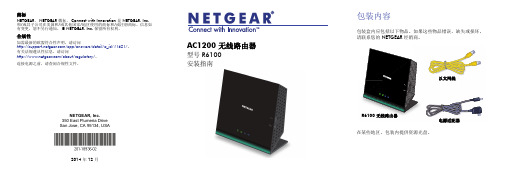
以太网线
R6100 无线路由器
电源适配器
在某些地区,包装内提供资源光盘。
1. 准备调制解调器。
拔下调制解调器的电源。如果有备用电池, 则取下电池。
2. 连接调制解调器。
插入调制解调器。放回电池。然后使用电缆 将调制解调器连接到路由器的互联网端口。
3. 打开路由器电源。
等待 WiFi LED 亮起。
• 确保路由器电量充足,并且其 WiFi LED 指示灯亮稳定蓝光。 • 为了确保浏览器未缓存先前的页面,请关闭并重新打开浏览器。
然后键入 。 • 如果计算机被设置为静态或固定 IP 地址 (极少见),请将其更改
为从路由器自动获取 IP 地址。
预设无线安全
该产品具有唯一的 WiFi 网络名称 (SSID) 和网络密钥 (密码)。默认 SSID 和密码是针对每个设备生成的 (就像序列号),以保护并尽可能 提供无线安全。此信息位于产品底部的标签上。
首次连接至路由器时,会出现网件精灵界面。按照网件精灵的步 骤连接到互联网。 如果没有显示网件精灵界面,请关闭并重新打开浏览器。在地址 栏中键入 。键入用户名 admin 和默认密 码 (password)。
4
如果未出现 NETGEAR 网件精灵
• 确保计算机连接到四个局域网以太网端口之一,或通过无线方式 连接到路由器。
NETGEAR 建议不要更改预设的 WiFi SSID 或密码。如果更改设置,则 标签上的 SSID 和密码将不再适用。
5
无线网络设置
在下面空白处记录标签上的预设无线设置以便参考。 WiFi 网络名称 (SSID): 网络密钥 (密码):
如果更改默认设置,请在此记录以便参考,并将本手册存放在安全的 地方:
F-Engine R4108 路由器硬件安装手册(V1.0)

F-ENGINE R4108 路由器硬件安装手册(V1.0)目录第1章产品概述 (1)1.1 产品简介 (1)1.2 技术特性 (2)1.3 产品规格 (3)1.3.1 硬件性能指标 (3)1.3.2 软件性能指标 (3)第2章 F-ENGINE R4108的介绍 (1)2.1 F-ENGINE R4108外观说明 (1)2.1.1 机箱 (1)2.1.2 单板插框说明 (1)2.1.3 电源分布 (2)2.2 F-ENGINE R4108通风散热系统 (2)2.3 F-ENGINE R4108模块简介 (3)2.3.1 系统主控板(MCU) (3)2.3.2 接口卡模块 (4)第3章安装前准备 (1)3.1 安全性建议 (1)3.1.1 安装系统的安全 (1)3.1.2 搬移的安全 (1)3.1.3 电气安全性 (1)3.1.4 激光安全性 (2)3.2 安装场地的要求 (2)3.2.1 通风要求 (2)3.2.2 温度和湿度要求 (2)3.2.3 洁净度要求 (3)3.2.4 电源要求 (3)3.3 系统接地要求 (3)3.4 系统连线要求 (4)3.4.1 安全接地 (4)3.4.2 雷电接地 (4)3.4.3 电磁兼容接地 (4)3.5 安装工具要求 (4)3.6 开箱验货检查要求 (5)第4章产品的安装 (1)4.1 安装流程 (1)4.2 安装确认 (1)4.3 安装机箱 (2)4.3.1 安装机箱于桌面 (2)4.3.2 安装机箱于机柜 (2)4.4 连接系统接地 (2)4.5 安装后检查 (3)4.5.1 机柜检查 (3)4.5.2 电缆连接检查 (3)4.5.3 电源检查 (3)4.6 连接监控口 (3)4.6.1 连接Console口 (4)4.7 搭建配置环境 (5)4.7.1 通过配置口(Console)搭建本地配置环境 (5)第5章硬件故障分析 (1)5.1 故障隔离 (1)5.1.1 电源和冷却系统故障 (1)5.1.2 端口、电缆和连接故障 (1)5.2 指示灯说明 (1)第6章路由器维护 (1)6.1 安装R4108主控板 (1)6.2 更换R4108主控板 (2)6.3 R4108主控板内存升级及BOOT ROM升级 (3)第1章产品概述1.1 产品简介F-ENGINE R4108高端路由器作为烽火网络有限责任公司推出的骨干路由器,产品致力于面向电信级运营网络和企业级核心网络;产品设计在保持对业界先进技术密切跟踪的同时,充分考虑了烽火网络多年在路由器领域的研发经验和技术积累,以及对市场的充分了解,提出了简便、适用、新颖的以交换为核心,分布式处理的多处理器体系结构。
博达路由器各模块安装

博达路由器模块安装手册目录第1章概述 (1)1.1 模块种类 (1)1.2 准备安装模块 (1)1.2.1 安全信息 (2)1.2.2 需要的工具和设备 (2)1.3 安装模块 (3)第2章各模块的安装 (4)2.1 安装以太网模块 (4)2.1.1 单路快速以太网电接口模块(RJ45)(NM-1FE-TX) (4)2.1.2 单路快速以太网光接口模块(多模)(NM-1FE-FX(MM)) (6)2.1.3 单路快速以太网光接口模块(单模)(NM-1FE-FX(SM)) (7)2.1.4 两路快速以太网电接口模块(RJ45)(NM-2FE-TX) (7)2.2 安装串口模块(NM-4T) (8)2.2.1 串行连接的一般介绍 (8)2.2.2 四串口模块 (10)2.3 安装复合网络模块(NM-1E1T1B、NM-1E2T、NM-2T1B) (13)2.3.1 NM-1E1T1B模块 (14)2.3.2 NM-1E2T模块 (14)2.3.3 NM-2T1B模块 (15)2.4 安装E1模块(NM-1CE1) (15)2.4.1 E1模块简介 (15)2.4.2 E1模块面板图 (16)2.4.3 E1模块说明 (16)2.5 安装ISDN BRI模块 (19)2.5.1 四路ISDN BRI S/T网络模块 (19)2.5.2 四路ISDN BRI S/T网络模块接口 (19)2.6 安装4UE1(NM-4UE1) (21)2.6.1 4UE1模块简介 (21)2.6.2 4UE1模块面板图 (21)2.6.3 NM-4UE1模块说明 (21)2.7 安装EM-1CE3模块 (24)2.7.1 1CE3模块说明 (24)2.7.2 1CE3模块与外部设备连接图 (26)2.8 安装EM-4/8/16CE1模块 (26)2.8.1 EM-4/8/16CE1模块简介 (26)2.8.2 EM-4/8/16CE1模块面板图 (26)2.8.3 EM-4/8/16CE1模块说明 (27)2.8.4 与接口配套的电缆 (34)2.8.5 EM-4/8/16CE1模块与外部设备连接图 (35)2.9 安装EM-4/8/16CT1模块 (36)2.9.1 EM-4/8/16CT1模块简介 (36)2.9.2 EM-4/8/16CT1模块面板图 (36)2.9.3 EM-4/8/16CT1模块说明 (37)2.9.4 与接口配套的电缆 (42)2.9.5 EM-4/8/16CT1模块与外部设备连接图 (43)2.10 安装EM-1POS-OC3_STM-1-SFP模块 (43)2.10.1 POS卡简介 (43)2.10.2 POS接口卡外观 (43)2.10.3 POS接口卡接口属性 (44)2.10.4 POS接口卡指示灯 (44)2.10.5 POS接口卡光连接器 (44)2.10.6 安装注意事项 (45)2.11 安装EM-1CPOS-OC3/STM-1-SFP模块 (45)2.11.1 EM-1CPOS-OC3/STM-1-SFP模块简介 (45)2.11.2 EM-1CPOS-OC3/STM-1-SFP模块面板图 (45)2.11.3 EM-1CPOS-OC3-STM1-SFP模块说明 (46)2.11.4 光连接器说明 (46)2.12 安装光电复用千兆以太网模块 (47)2.12.1 千兆以太网模块介绍(EM-1GE-TX/SFP) (47)2.12.2 连接千兆以太网电接口 (47)2.12.3 连接千兆以太网光接口 (48)2.12.4 模块LED的说明 (49)第1章 概述1.1 模块种类目前提供了网络模块(NM )EM 模块两种,具体详细产品型号参见下表。
NETGEAR 智能交换机安装指南说明书
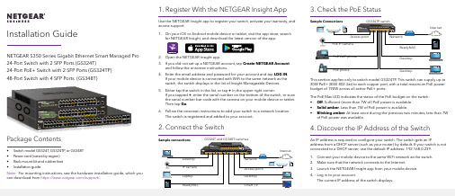
1. Register With the NETGEAR Insight AppUse the NETGEAR Insight app to register your switch, activate your warranty, and access support.1. On your iOS or Android mobile device or tablet, visit the app store, searchfor NETGEAR Insight, and download the latest version of the app.2. Open the NETGEAR Insight app.3. If you did not set up a NETGEAR account, tap Create NETGEAR Accountand follow the onscreen instructions.4. Enter the email address and password for your account and tap LOG IN .24-Port Switch with 2 SFP Ports (GS324T)24-Port PoE+ Switch with 2 SFP Ports (GS324TP) 3. Check the PoE StatusNETGEAR, Inc.350 East Plumeria DriveSan Jose, CA 95134, USA NETGEAR INTL LTDBuilding 3, University Technology Centre Curraheen Road, Cork, Ireland© NETGEAR, Inc., NETGEAR and the NETGEAR Logo are trademarks of NETGEAR, Inc. Any non‑NETGEAR trademarks are used for reference purposes only.SupportThank you for purchasing this NETGEAR product. You can visithttps:///support/ to register your product, get help, access the latest downloads and user manuals, and join our community. We recommend that you use only official NETGEAR support resources.Si ce produit est vendu au Canada, vous pouvez accéder à ce document en français canadien à https:///support/download/.(If this product is sold in Canada, you can access this document in Canadian French at https:///support/download/.)For regulatory compliance information including the EU Declaration of Conformity, visit https:///about/regulatory/.See the regulatory compliance document before connecting the power supply.Do not use this device outdoors. If you connect cables or devices that are outdoors to this device, see https:///000057103 for safety and warranty information.November 20185. Configure the SwitchWe recommend that you use a web browser on a computer or tablet to configure the switch.Note: If your computer is a Mac, use the NETGEAR Switch Discovery Tool, as described in the following section.1. Open a web browser from a computer or tablet connected to the samenetwork as your switch.You can use a WiFi or wired connection. 2. Enter the IP address of the switch.3. Enter the password.The default password is password . We recommend that you change the password to a more secure password.4. Click the Login button.Other Discovery and Configuration MethodsThe NETGEAR Switch Discovery Tool and the Smart Control Center Utility let you discover the IP address and configure the switch. •NETGEAR Switch Discovery Tool . You can use a Mac or a 64-bit Windows-based computer that is on the same network as the switch. You can use a WiFi or wired connection. When you discover the switch, this tool provides access to the local browser interface to c onfigure the switch. To download the NETGEAR Switch Discovery Tool, visit/support/product/netgear-switch-discovery-tool.aspx .•Smart Control Center Utility . You can use a Windows-based computer that is on the same network as the switch. This utility requires Adobe Air. If Adobe Air is not detected during Smart Control Center Utility installation, you are prompted to allow Adobe Air to be installed. To download this utility, visit /support/product/SCC .Note: If you cannot discover or configure the switch, you might need totemporarily disable the firewall, Internet security, or antivirus programs. Make sure to reenable these security services after you discover and configure the switch.PoE ConsiderationsThe PoE and PoE+ power supplied by the GS324TP switch is prioritized inascending port order (from port 1 to port 24), with a total power budget of 190 watts. If the power requirements for the attached powered devices (PDs) exceed the total power budget of the switch, the PD on the highest-numbered port is disabled to make sure that the PDs that are connected to the higher-priority, lower-numbered ports are supported first.The following table describes the PoE classes and switch allocations.Device ClassStandard ClassDescriptionPowerReserved by the DevicePower Delivered to the Device*0PoE and PoE+Default power (full)15.4W 0.44W–12.95W 1PoE and PoE+Very low power 4.0W 0.44W–3.84W 2PoE and PoE+Low power 7.0W 3.84W–6.49W 3PoE and PoE+Mid power 15.4W 6.49W–12.95W 4PoE+ onlyHigh power30.0W12.95W–25.5W* Calculated with the maximum cable length of 328 feet (100 meters). Shorter cable lengths will provide power closer to the power reserved by the switch.。
WLAN设备安装说明

WLAN设备安装说明为了规范局域网交换机,AP,天线等WLAN设备的安装,根据相关设备厂家提供的设备安装手册所规定的要求制定本说明。
WLAN热点的设备安装应当不低于本说明的要求。
一、交换机(或ONU)安装说明1、交换机(或ONU)应安装在网络箱内,并做好接地。
安装位置确保无强电、强磁和强腐蚀性设备的干扰。
安装于室外的交换机见图:交换机&AP室外安装示意图。
网络箱应比地面抬高300mm以防水浸。
交换机和AP等设备应放置在稳固的支撑板上,并做好固定。
安装在弱电竖井内、楼梯间墙壁上、电梯机房等室内环境的交换机及网络向见图:交换机(ONU)室内安装示意图。
各设备应安装在网络箱内并做好固定,然后进行连线。
2、网络箱内电源插板至少有两芯及三芯插座各一个。
且必须有良好的接地系统,并应符合保护地线电阻值。
单独设置接地体时,电阻值不应大于10Ω;采用联合接地体时,电阻值不应大于5Ω。
3、当使用POE供电模块时,将POE供电模块安装于网络箱内。
需用牢固固定,不允许悬空放置或直接将POE供电模块直接堆叠在交换机上,保持通风良好,可散热。
4、交换机(或ONU)应无损伤、掉漆的现象。
二、AP安装说明1、设备安装必须符合工程设计要求。
如果设备的安装位置需要变更,必须征得设计和建设单位的同意,并办理设计变更手续。
2、放置在楼顶的AP通过超五类线沿墙布放连接至局域网交换机(或ONU)。
3、放置在一个单元内的AP在与楼宇间交换机连接时使用光缆连接(交换机和AP侧分别加光电转换模块)。
AP与楼宇间光缆采用地埋方式布放,进入楼宇后光缆采用沿墙布放并外套PVC管。
光缆的布放原则见第四节。
4、如果AP安装在弱电井内,则需做好防尘等安全措施,为防止AP被盗,建议在固定架加锁或是将AP安装在定做机箱之中,并保持通风良好、通气孔畅通,保持工作环境清洁无尘。
5、如果AP壁挂安装在大楼墙面上,必须做好防盗措施,建议将AP安装在定做机箱之中,并保持通风良好、通气孔畅通,保持工作环境清洁无灰尘。
TP-LINK TL-R5210PE-H安装手册说明书

Enterprise Networking Solution安装手册2.5G 光电复合PoF•AC一体VPN路由器TL-R5210PE-H声明Copyright © 2022 普联技术有限公司版权所有,保留所有权利未经普联技术有限公司明确书面许可,任何单位或个人不得擅自仿制、复制、誊抄或转译本手册部分或全部内容,且不得以营利为目的进行任何方式(电子、影印、录制等)的传播。
为普联技术有限公司注册商标。
本手册提及的所有商标,由各自所有人拥有。
本手册所提到的产品规格和资讯仅供参考,如有内容更新,恕不另行通知。
除非有特殊约定,本手册仅作为使用指导,所作陈述均不构成任何形式的担保。
声明III相关文档除本安装手册外,我们还提供以下文档的电子版本。
如需获取最新产品资料,请如果通过相关文档的指导仍不能解决问题,请您直接联系TP-LINK技术支持服安装手册简介《安装手册》主要介绍了TL-R5210PE-H的硬件特性、安装方法以及在安装过程中应注意事项。
包括以下章节:第1章:产品介绍。
简述路由器的基本功能特性并详细介绍外观信息。
第2章:产品安装。
指导路由器的硬件安装方法以及注意事项。
第3章:硬件连接。
指导路由器与其他设备之间的连接及注意事项。
第4章:配置指南。
介绍快速设置路由器的方法及路由器上云步骤。
附录A:常见故障处理。
附录B:技术参数规格表。
说明:在安装设备之前及安装设备过程中为避免可能出现的设备损坏及人身伤害,请仔细阅读本手册相关内容。
相关文档阅读对象本手册适合下列人员阅读:网络工程师网络管理人员约定在本手册以下部分,如无特别说明,所提到的路由器是指2.5G 光电复合PoF•AC一体VPN路由器,产品图片仅为示意说明,请以实际机型为准。
本手册采用了如下几种醒目标志来表示操作过程中应该注意的地方,这些标志的意义如下:IIIIV目录目录第1章 产品介绍 —————————————011.1 产品简介 ......................................................011.2 产品外观 (01)第2章 产品安装 —————————————032.1 物品清单 ......................................................032.2 安装注意事项 ..............................................032.3 安装工具准备 ..............................................052.4 产品安装 (05)第3章 硬件连接 —————————————073.1 连接线缆 ......................................................073.2 连接电源 ......................................................083.3 设备初始化 ..................................................083.4 安装后检查 .. (08)第4章 配置指南 —————————————094.1 设置计算机 ..................................................094.2 设置路由器 ..................................................094.3 登录成功 ......................................................134.4 云管理 (14)附录A 常见故障处理 ———————————15附录B 技术参数规格 ———————————16012.5G 光电复合PoF•AC一体VPN路由器安装手册产品介绍第1章 产品介绍1.1 产品简介TL-R5210PE-H是TP-LINK全新开发的2.5G 光电复合PoF•AC一体VPN路由器系列产品,内置AC (无线控制器)和PoF (光纤供电)功能,可统一管理TP-LINK 光电复合AP产品并为其供电,用户无需额外购置AC设备,直接搭配TP-LINK光电复合AP产品即可组建无线网络,管理便捷,性价比高。
NETGEAR M6100系列前端面板及XCM8903架架式交换机系列安装指南说明书
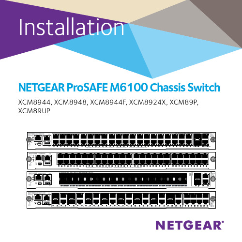
NETGEAR ProSAFE M6100 Chassis Switch XCM8944, XCM8948, XCM8944F, XCM8924X, XCM89P, XCM89UPContentsM6100 Series Front Panels (3)Before Installing the Switch Blade (4)Install the Chassis (5)Install the Fan Tray (6)Install the Switch Blade (7)Install the Power Supply (9)Install Optional PoE (XCM89P) or UPoE (XCM89UP) Board (10)Configure the Switch Blade (11)M6100 Series Front Panels XCM8924XBefore Installing the Switch BladeThe M6100 series switch blades are designed to be installed inthe XCM8903 rack-mount switch chassis. NETGEAR recommends installing the XCM8903 rack-mount chassis into a rack before installing any switch blades. For more information about how to install the XCM8903 rack-mount switch chassis, see the XCM8903 Hardware Installation Guide.3. Screw the rest of the bracket to the rack.Install the Fan Tray¾To install the fan tray:1. Carefully slide the fan tray all the way into the fan tray bay atthe rear of the chassis.The fan tray is connected to power when it has been inserted completely into the fan tray bay.2. Screw the fan tray to the rear of the chassis using the includedscrews.Install the Switch Blade¾To install a switch blade in a M6100 series chassis switch:1. Select a slot for the switch blade.2. Remove a blank front panel from the chassis slot, if necessary.Any unoccupied switch blade slot in the chassis must have ablank faceplate installed to ensure satisfactory protection from EMI and to maintain adequate airflow through the chassis.3. Remove the switch blade from the antistatic packaging.CAUTION: To prevent ESD damage, hold the switch blade bythe metal rail and front panel only. Never touch thecomponents on the PCB or the pins on any of theconnectors.4. Verify that the switch blade injector-ejector handles are open.5. Keep the injector-ejector handles in the open position as youslide the switch blade into the chassis slot.CAUTION: Do not slide the switch blade into the open chassis slot if the injector-ejector handles are in the latchedposition.6. Using both hands, push both handles toward the center of the7. Use your fingers or a screwdriver to turn the front panel screwson each injector-ejector handle clockwise and completelydown.When the screw is fully tightened, the yellow band around the captive screw is completely hidden.CAUTION: Be careful to avoid over torquing and stripping the screw heads.Install the Power Supply¾To install the power supply:1. Carefully slide the power supply all the way into the powersupply bay until it clicks into place.CAUTION: Do not slam the power supply into the systembackplane. Use the locking handle to secure thepower supply in the power supply bay.2. Repeat Step 1 to install each additional power supply.3. After all the power supplies have been installed, connect anAC power cord to the AC input connector below each power supply.WARNING: Be sure that the source outlet is properly grounded before plugging the AC power cord into the inputconnector.Install Optional PoE (XCM89P) or UPoE (XCM89UP) BoardYou can install an optional PoE (XCM89P) or UPoE (XCM89UP) board into the XCM8944 and XCM8948 switch blades.¾To install the optional PoE (XCM89P) or UPoE (XCM89UP) board:1. Remove the switch blade from the chassis.2. Connect the optional board and secure it with the attachedConfigure the Switch BladeYou can manage your switch through its web management interface or by using the command-line interface (CLI) through a console port. This guide shows you how to configure your switch usingthe web management interface. It also covers using the CLI to determine a DHCP-assigned IP address or using ezconfig to assign a static IP address. For more information about CLI management, see the M6100 CLI Reference Manual and the M6100 Software Administration Manual.When configuring your switch, connect your switch to one of the numbered ports on the switch’s front panel. Do not connect to the Out-of-Band (OoB) port for initial switch configuration.Note: Use the OoB port to manage the switch only after the switch has been configured for your network. For more informationabout switch management using the OoB port, see the M6100CLI Reference Manual and the M6100 Software AdministrationManual.To configure your switch using web management, use one of the following procedures, depending on how your Windows computer is set up:• Computer is in DHCP client mode without DHCP server.• Computer uses a static IP address.• Computer is in DHCP client mode with DHCP server.Computer in DHCP Client Mode Without a DHCP ServerThe switch assumes a default IP address of 169.254.100.100 and a subnet mask of 255.255.0.0. The switch is in the same subnetused by the computer NIC port when in DHCP-client mode without a DHCP server present. Use this IP value to log in to the switch. Computer with a Static IP AddressWhen the computer is in this mode, the switch must also be assigned a static IP address. To assign a static IP address, connect a VT100/ANSI terminal or a workstation to one of the switch’s console ports. A cable for the mini USB port and a straight-through RJ-45 cable are supplied.¾To configure the switch:1. Start a terminal emulation program (TEP).2. Connect your computer to a mini USB or RJ-45 console port onthe front panel of the blade.computer.Note: You might need to install the USB serial port driver available on the CD included with the package before you can use the miniUSB port on the computer to connect to the switch.3. Configure the TEP to use the following settings:• Baud rate. 115200 bps• Data bits. 8• Parity. None• Stop bit. 1• Flow control. None4. At the command prompt User:, log in to the switch using theuser name admin and press the Enter key.5. At the password prompt press the Enter key.No password is required for initial configuration.6. At the next command prompt, type ezconfig and press theEnter key.The ezconfig utility is now running on the switch.7. Use the following example to set up your static IP address andsubnet mask.Note: Make sure that the selected switch IP address is in that same subnet as the computer.8. Connect your computer to one of the numbered ports on theswitch’s front panel.9. Enter the IP address you configured in the address field of abrowser.A login screen displays.10. Enter admin for the user name and leave the password fieldblank.11. Click the Login button.The system information screen displays.12. Configure the switch for your network.For more information on configuration settings and options, see the M6100 Software Administration Guide.Computer in DHCP Client Mode with a DHCP ServerBy default, the switch is configured as a DHCP client to obtain its IP address from a DHCP server in the connected network. You must access the switch from either the mini USB or RJ-45 console port.¾To configure the switch:1. Make sure that the switch is connected to a DHCP server.2. Start a terminal emulation program (TEP).3. Connect your computer to a mini USB or RJ-45 console port onthe front panel of the blade.4.• Data bits. 8• Parity. None• Stop bit. 1• Flow control. None5. Type the show network command and press the Enter key.A screen displays that shows the active switch IP address.6. Connect your computer to one of the numbered ports on theswitch’s front panel.7. On the computer that is connected to the switch, enter theswitch IP address in the address field of a browser.A login screen displays.8. Enter admin for the user name and leave the password fieldblank.9. Click the Login button.The system information screen displays.10. Configure the switch for your network.For more information about configuration settings and options, see the M6100 Software Administration Guide.NETGEAR, Inc.350 East Plumeria DriveSan Jose, CA 95134, USA August 2014Technical SupportThank you for selecting NETGEAR products. After installing your device, locate the serial number on the label of your product and use it to register your product at https:// . You must register your product before you can use NETGEAR telephone support. NETGEAR recommends registering your product through the NETGEAR website.To contact NETGEAR for support, go to /general/contact or call (US only) 1-888-NETGEAR. In other countries, visit /general/contact/default.aspx for phone numbers . For product updates and web support, visit .NETGEAR recommends that you use only the official NETGEAR support resources. You can get the user manual online at or through a link in the product’s user interface.TrademarksNETGEAR, the NETGEAR logo, and Connect with Innovation are trademarks and/or registered trademarks of NETGEAR, Inc. and/or its subsidiaries in the United States and/or other countries. Information is subject to change without notice. © NETGEAR, Inc. All rights reserved.ComplianceFor the current EU Declaration of Conformity, visit: /app/answers/detail/a_id/11621/.For regulatory compliance information, visit: /about/regulatory/.。
瑞斯康达EPON配置手册_2008-04-27_

介绍了EPON OLT设备的安装过程、设备启 动、软硬件维护与监控等内容。
《瑞斯康达交换机软件配置指导》 介绍了EPON OLT设备以太网交换系统部分
的配置与其所支持的特性。
《瑞斯康达交换机软件命令手册》 介绍了EPON OLT设备以太网交换系统部分
的配置命令和详细解释。
文档结构:
本用户手册包括以下内容: 第一章:命令行使用方法
———————————————————————————————————————
声明
Copyright ©2007 北京瑞斯康达科技发展有限公司 版权所有,保留一切权利。 非经本公司书面许可,任何单位和个人不得擅自摘抄、复制本书内容的部分或全部,并不得 以任何形式传播。
是北京瑞斯康达科技发展有限公司的注册商标。 对于本手册中出现的其它商标,由各自的所有人拥有。 这里的产品和服务名称都为北京瑞斯康达科技发展有限公司的商标。 由于产品版本升级或其它原因,本手册内容会不定期进行更新。除非另有约定,本手册仅作 为使用指导,本手册中的所有陈述、信息和建议不构成任何明示或暗示的担保。
2.2.2
系统启动文件....................................................................................................... 11
2.3 管理接口配置 .......................................................................................................... 11
3.1.6
P2P 访问控制 .......................................................................................................17
RG-EG-E 系列路由器硬件安装手册说明书

RG-EG-E 系列路由器文档版本:V1.0版权声明copyright © 2021锐捷网络保留对本文档及本声明的一切权利。
未得到锐捷网络的书面许可,任何单位和个人不得以任何方式或形式对本文档的部分内容或全部进行复制、摘录、备份、修改、传播、翻译成其他语言、将其全部或部分用于商业用途。
以上均为锐捷网络的商标。
本文档提及的其他所有商标或注册商标,由各自的所有人拥有。
免责声明您所购买的产品、服务或特性等应受商业合同和条款的约束,本文档中描述的全部或部分产品、服务或特性可能不在您的购买或使用范围之内。
除非合同另有约定,锐捷网络对本文档内容不做任何明示或默示的声明或保证。
由于产品版本升级或其他原因,本文档内容会不定期进行更新。
锐捷网络保留在没有任何通知或者提示的情况下对文档内容进行修改的权利。
本手册仅作为使用指导。
锐捷网络在编写本手册时已尽力保证其内容准确可靠,但并不确保手册内容完全没有错误或遗漏,本手册中的所有信息也不构成任何明示或暗示的担保。
前 言感谢您使用锐捷网络产品,本手册为您提供了详细的硬件安装指南。
使用范围本手册主要介绍了产品在功能上和物理上的一些特性,提供了安装步骤、故障排除、技术规格,以及电缆和连接器的规格和使用准则。
适用于想对上述内容进行了解且在安装和维护网络硬件方面具有一定经验的用户。
同时假定该款产品的用户熟知相关术语和概念。
技术支持锐捷睿易官方网站:https:///锐捷睿易在线客服:https:///?p=smb锐捷网络官方网站服务与支持版块:https:///service.aspx7天无休技术服务热线:4001-000-078锐捷睿易技术论坛:/常见问题搜索:https:///service/know.aspx锐捷睿易技术支持与反馈信箱:*********************.cn锐捷网络服务公众号:【锐捷服务】扫码关注文档格式约定本书采用各种醒目标志来表示在操作过程中应该特别注意的地方,这些标志的意义如下:注意、警告、提醒操作中应注意的事项。
锐捷RSR10(20)系列路由器用户安装手册V1.81-10.3(5)

¾ 网络管理员
3
本书约定
1、通用格式约定 宋体:正文采用 5 号宋体。 楷体:警告、说明等提示等内容一律用楷体,并且在内容前后增加线条与正文隔离。
Terminal Display 格式:自定义的 Terminal Display 格式,英文 Courier New ,中文宋体,文字大 小 8.5 ,表示屏幕输出信息此外屏幕输出。信息中夹杂的用户从终端输入的信息,采用加粗字体表示。
锐捷网络客户服务中心可以为所有的客户提供所需要的技术帮助:产品、技术 和解决方案。对于客户遇到的产品的安装,软件的配置问题,以及其它的网络性能 的问题,客户服务中心都将提供迅速的技术支持。 ¾ 技术支持网站: ¾ 技术支持信箱:service@ ¾ 呼叫中心热线: 4008-111-000 ¾ 客户服务投诉热线:0591-83057315
®
锐捷 RSR10/RSR20 系列路由器 用户安装手册
V1.81
版权声明
福建星网锐捷网络有限公司©2000-2010
版权所有,保留一切权利。
本手册所有权益由福建星网锐捷网络有限公司独家拥有。没有
经过本公司书面许可,任何单位和个人不得擅自摘抄、复制本
书内容的部分或者全部,并且不得以任何形式传播。
福建星网锐捷网络有限公司保留以后对本手册描述的产品和手
建议: 建议由熟悉电气环境、线缆连接以及有实际安装和配置路由器经验的专业技术人员进 行安装和配置。
这份手册包括以下章节: z 第一章 产品介绍 介绍了锐捷 RSR10/RSR20 系列路由器的产品介绍以及系统特性。 z 第二章 安装路由器前的准备 描述了安装锐捷 RSR10/RSR20 系列路由器的环境要求、安装前和安装过程中需要注意的 事项、安装所需工具。 z 第三章 路由器的安装 介绍锐捷 RSR10/RSR20 系列路由器的机械安装方法、电源连接方法、备份口线缆连接方 法以及配置口线缆连接方法。 z 第四章 启动和配置路由器 介绍路由器初始启动信息及路由器进行的初始配置。 z 第五章 安装故障处理 介绍了如何处理安装过程中可能出现的问题及故障处理。 z 第六章 线缆使用说明 介绍了路由器常见配套线缆使用方法。
InHand Networks CR202 便携式4G路由器快速安装手册V1.0—2023.2说明书

InHand Networks CR202 Portable 4G Router Quick Installation ManualV1.0—2023.2ContentsOverview (1)1 Packing List (1)2 Panel Introduction (2)3 Installation (2)3.1 SIM card Installation (2)3.2 Antenna Installation (3)4Access to Internet (3)4.1 Wired to Internet (4)4.2 SIM Card Dialup (6)4.3 Wi-Fi to Internet (7)5 Quick-Use Guidance (9)5.1 Restore to Factory Setting (9)5.1.1 Web Setting (9)5.1.2 Hardware Restore (10)5.2 Import/Export Configuration (10)5.3 Log and Diagnose Record (10)5.4 Connect to InHand platform (10)6 Description of Indicator (12)OverviewThis manual is a guide for the installation and operation of CR202 routers from InHand Networks. Please confirm the product model and packaging accessories (cable, antenna), and purchase SIM cards from local network operatorsAll statements, information and recommendations in this manual do not constitute any expressed or implied warranty.1 Packing ListEach CR202 product includes common accessories, please check carefully when you receive our products. If there is any missing or damage, please contact InHand sales staff.InHand can provide customers with optional accessories according to different field. Please refer to the list of optional accessories for detailed information.Packing list2 Panel Introduction3 InstallationPrecautions for installation:●Power supply: Internal battery or Type-C interface (5V/2A), please pay attention tothe power voltage level.●Environment: Working temperature: -10℃~50℃, storage temperature: -20℃~60℃, equipment surface may be high temperature, please consider the surrounding environment before installation.●Support to be mounted with bracket. Avoid direct sunlight, away from heat sourceor strong electromagnetic interference●Check for cables and connectors required for installation.3.1 SIM card InstallationCR202 supports single nano SIM card or eSIM. Please install the SIM card like below if use nano SIM card.3.2 Antenna InstallationRotate the metal interface clockwise until the movable part cannot be rotated, do not hold the black glue stick to twist the antenna.4A ccess to InternetCR202 supports three ways of accessing to Internet: wired, cellular and Wi-Fi.When CR202 does not access to Internet via cellular, please disable Cellular in “Network>>Cellular”, otherwise the device will restart after trying dial up and fail for several times.4.1 Wired to InternetStep 1: Connect power and Ethernet cable to CR202, connect WAN/LAN1 port to public network, and LAN2 to PC.Step 2: Configure PC to be in the same network segment as the IP address of the router.(1) Enable PC to obtain an IP address from DHCP automatically (recommended).(2) Or configure a fixed IP address in the same network segment as the router for PC. The IP address should be one of the address in 192.168.2.2~192.168.2.254, Subnet mask should be 255.255.255.0, and Default gateway should be 192.168.2.1. DNS server should be 8.8.8.8 or the address of ISP’s DNS server.Step 3: Access to the default IP address 192.168.2.1 in a browser, enter username and password (adm/123456 by default) in pop-up window and then access to router’s WEB management page. If the browser alarms the connection is not private, show advanced, and proceed to access to the address.Step 4: Create a WAN port in “Network >> WAN” in the left menu. Configure an IP address for WAN port and let the router connect to Internet.There are there methods to obtain IP address: Dynamic DHCP (recommend). Static IP (Click Apply & Save after configure manually) and ADLS Dialup (Click Apply & Save after configure manually).Obtain IP address by Dynamic Address (DHCP)Obtain IP address by Static IPObtain IP address by ADSL DialupStep 5: Check th e connectivity in “Tools >> PING”.4.2 SIM Card DialupStep 1: Insert the SIM card when device is power off. Connect 4G antenna to the router, and connect PC to router. Then power on.Note:When insert or plug out SIM card, please power off the device to prevent data loss orStep 2: Open a browser and access to router’s WEB management page. (refer to 4.1) Step 3: Click “Network >> Cellular”, set profile. The device enables the cellular by default, it will connect to Internet within a few minutes. If the device cannot connect to Internet, please disable and restart dialup. (If you use a private network SIM card, you also need to configure APN parameter)Step 4: Check the dialup status in “Status”, if it shows Connected and there is IP address and other dialup parameters, the router has connect to Internet by SIM card.4.3 Wi-Fi to InternetStep 1: Connect Wi-Fi antenna, and connect PC to the device. Access to router’s WEB management page. (refer to 4.1)Step 2: Set Wi-Fi mode: AP or STA.AP mode (default mode):CR202 acts as an accsess point to radiate wireless signals, and other terminal devices can connect CR202 to access the Internet. It is necessary to ensure that CR202 itself has been connected to the Internet through wired orcellular. AP mode supports setting SSID name and encryption method, and terminal devices will need to input password when connecting.STA mode: CR202 connects to other AP Wi-Fi device to access the Internet.1.Select WLAN Type to STA in “Network>>Switch WLAN Mode” and save. Thenreboot the router.2.Click “Scan”to scan available AP in “Network>>WLAN Client”, and clickConnect to choose one of AP.3.Configure Wi-Fi parameters and save. Then check the connection status in“Status>>Network Connection”.4.Configure WAN mode in “Network>>WAN(STA)”, set WA N parameters for Wi-Fi.5 Quick-Use Guidance5.1 Restore to Factory Setting5.1.1 Web SettingLogin to the WEB management page, click on the "System>> Config Management" menu in the navigation tree. Click "Restore default configuration" button, router will restore to default settings after reboot.5.1.2 Hardware RestoreTo restore to default settings via the reset button, please perform the following steps:1. Press the RESET button immediately after power on the device.2. When System LED is steady on, release RESET button, system LED will blink, and press the RESET button again.3. When System LED blinks slowly, release the RESET button. The device has been restored to default settings and will start up normally later.5.2 Import/Export ConfigurationClick "System >> Config Management", click “Browse” in Router Configuration, select a configuration file, and click Import to import the configuration file to the router.Click Backup running-config to export configuration.5.3 Log and Diagnose RecordClick "Status >> log" and check the system log in router. Click Download Log File button to download log from router, and click Download System Diagnosing Data to download diagnose record from router.5.4 Connect to InHand platformMake sure that router has already connect to Internet. Click "Service>>Device Manager" to set router to connect to InHand DM platform. https:// is the server for China, and https:// is the server for global.Fill in your DM account in Registered Account then click "Apply" to save the configuration.If you don’t have DM account, please click "Sign up/Sign in" after select server, then you will be directed to InHand Device Manager website, please follow the instruction to register an account.Login your account in Device Manager, and add your device in “Gateways”, named your device and fill in the serial number from device, then you can manage your router in DM.You can find the serial number in "Status>>System", or you can find it at the back of the device.6 Description of Indicator。
WL-RF610型产品说明书
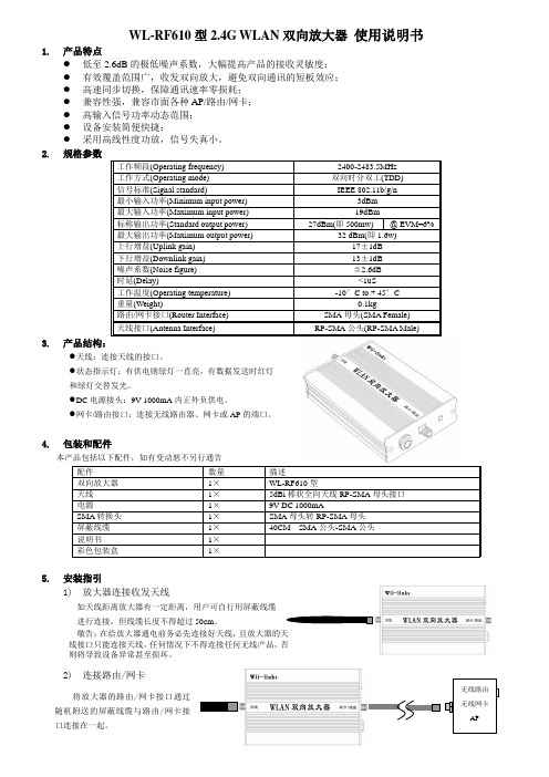
WL-RF610型2.4G WLAN 双向放大器 使用说明书1. 产品特点● 低至2.6dB 的极低噪声系数,大幅提高产品的接收灵敏度; ● 有效覆盖范围广,收发双向放大,避免双向通讯的短板效应; ● 高速同步切换,保障通讯速率零损耗; ● 兼容性强,兼容市面各种AP/路由/网卡; ● 高输入信号功率动态范围; ● 设备安装简便快捷;● 采用高线性度功放,信号失真小。
2. 规格参数3. 产品结构:● 天线:连接天线的接口。
●状态指示灯:有供电则绿灯一直亮,有数据发送时红灯和绿灯交替发光。
● D C 电源接头:9V 1000mA 内正外负供电。
● 网卡/路由接口:连接无线路由器、网卡或AP 的端口。
4. 包装和配件本产品包括以下配件,如有变动恕不另行通告5. 安装指引1) 放大器连接收发天线如天线距离放大器有一定距离,用户可自行用屏蔽线缆 进行连接,但线缆长度不得超过50cm 。
敬告:在给放大器通电前务必先连接好天线,且放大器的天线接口只能连接天线,任何情况下不得连接任何无线产品,否则将导致设备异常甚至损坏。
2) 连接路由/网卡将放大器的路由/网卡接口通过随机附送的屏蔽线缆与路由/网卡接口连接在一起。
小贴士:在连接前请务必先确认你的路由器/网卡接口与屏蔽线缆自带的接口是否兼容,若不兼容,可使用随机附送的转接头(已事先加装到屏蔽线上)或者另行购买其他与之匹配的转接头。
用户也可以使用其他屏蔽线缆进行连接,但线缆长度需尽量短,最好不要超过3m 。
3) 检查第1和第2步,确认连接是正确的才能进行下一步。
4) 将放大器通上电此时放大器的状态指示灯呈现绿色,有信号发送时,指示灯会转为红色,信号发送越频繁,指示灯越亮。
5)小贴士:用户可以用第三方软件如Network Stumbler 或WirelessMon 侦测路由或网卡的信号强度,边调整天线角度使信号达到最强。
6.注意事项● 请勿将本产品靠近微波炉以及其他无线设备,使用时确保距离此类装置1m 以上。
Ruijie RG-EG系列路由器硬件安装及参考指南说明书
Ruijie RG-EG Series RoutersHardware Installation and Reference GuideCopyright StatementRuijie Networks©2020Ruijie Networks reserves all copyrights of this document. Any reproduction, excerption, backup, modification, transmission, translation or commercial use of this document or any portion of this document, in any form or by any means, without the prior written consent of Ruijie Networks is prohibited.Exemption StatementThis document is provided “as is”. The contents of this document are subject to change without any notice. Please obtain the latest information through the Ruijie Networks website. Ruijie Networks endeavors to ensure content accuracy and will not shoulder any responsibility for losses and damages caused due to content omissions, inaccuracies or errors.PrefaceThank you for using our products. This manual will guide you through the installation of the device.This manual describes the functional and physical features and provides the device installation steps, hardware troubleshooting, module technical specifications, and specifications and usage guidelines for cables and connectors.AudienceIt is intended for the users who have some experience in installing and maintaining network hardware. At the same time, it is assumed that the users are already familiar with the related terms and concepts.Obtaining Technical Assistance●Ruijie Networks Website: https:///●Technical Support Website: https:///support●Case Portal: https://●Community: https://●Technical Support Email: *****************************●Skype: *****************************Related DocumentsSymbol ConventionsMeans reader take note. Notes contain helpful suggestions or references.Means reader be careful. In this situation, you might do something that could result in equipment damage or loss of data.1 Product OverviewFeatured with global-leading semiconductor technologies and communication control technologies, Ruijie EG series router is a data communication product developed by Ruijie Networks with independent intellectual property right. The EG series router is designed according to international standards, similar to the mainstream router products in the international market. By reading this manual, a network administrator familiar with mainstream router configuration commands can use this device without training.1.1 RG-EG105G-PSpecificationsPlease avoid the vibration and collision in the process of moving and usage.Products should be transported in original package.RG-EG105G-P is a Class-A product which may cause radio interference in the living environment. In such a case, the user may need to take feasible measures against such interference.AppearanceFigure 1-1 Front Panel of RG-EG105G-PFigure 1-2 Back Panel of RG-EG105G-PInterfaceLED IndicatorButton1.2 RG-EG105G SpecificationsPlease avoid the vibration and collision in the process of moving and usage.Products should be transported in original package.RG-EG105G is a Class-A product which may cause radio interference in the living environment. In such a case, the user may need to take feasible measures against such interference.AppearanceFigure 1-3 Front Panel of RG-EG105GFigure 1-4 Back Panel of RG-EG105GInterfaceLED IndicatorButton1.3 RG-EG105GWSpecificationsPlease avoid the vibration and collision in the process of moving and usage.Products should be transported in original package.Since there are numerous types of U-disk, we cannot ensure that the system supports all of them. The Kingston and SanDisk U-disk with FAT 32 are recommended to be used.AppearanceFigure 1-5 Front Panel of RG-EG105GWFigure 1-6 Back Panel of RG-EG105GWInterfaceLED IndicatorButton1.4 RG-EG210G-P SpecificationsPlease avoid the vibration and collision in the process of moving and usage.Products should be transported in original package.RG-EG210G-P is a Class-A product which may cause radio interference in the living environment. In such a case, the user may need to take feasible measures against such interference.AppearanceFigure 1-7 Front Panel of RG-EG210G-PFigure 1-8 Back Panel of RG-EG210G-PInterfaceLED IndicatorButton2 Preparation2.1 Safety PrecautionThe router acts as the critical transfer station of network connections, and its normal service is crucial to the normal operation of the entire network.●Do not place the device in a watery place and prevent any liquid from entering into it.●Keep the device away from heat sources.●Ensure the normal grounding of device.●Wear an anti-static wrist strap to install and maintain the device.●Do not wear loose clothes to avoid hooking any parts. Before operation, tighten your band, shawl and sleeves.●Keep tools and parts away from the walkway to avoid damage.●Use the uninterruptible power supply (UPS) to avoid power failure and other interferences.●If the system time is incorrect, check whether you have set the clock. If the clock is not set, the time may not becorrect; if the clock has been set precisely and the time is still incorrect, the built-in button cell of device may have ran out, which is typically happened after 10-year service.●Install and use the device in restricted access locations.Use of wrong battery may cause damage to the device. Do not replace the battery by yourself. Please contact the technical support for help.Install and use the device in restricted access locations.Invite professionals and related technicians to install this type of device.Where a plug on the power supply cord is used as the disconnect device, the installation instructions shall state that for pluggable equipment, the socket-outlet shall be easily accessible. For pluggable equipment intended for installation by an ordinary person, the installation instructions shall be made available to the ordinary person.2.2 Installation EnvironmentRuijie EG series router products are for indoor use only. To ensure normal operation and prolong their service life, the installation site must meet the following requirements:2.2.1 Temperature/humidity requirementsTo ensure normal operation and prolong the service life of the device, the equipment room must maintain constant temperature and humidity. If the equipment room is overheated for a long time, the insulation materials may result in defective insulation and even electric leakage. If the relative humidity is low, the insulation spacer may result in dry shrinkage, which will make screws looser and easily generate static electricity in the dry environment, thus damaging the interior circuits on the device. Excessively high temperature will accelerate the aging of insulation materials andcompromise the reliability and even service life of the device. The temperature/humidity requirements are shown below (detailed difference between products is described in Product Overview):The temperature/humidity of working environment indicates the value measured at 1.5 m above the floor and 0.4 m ahead of the equipment frame when there is no protection plate on the front and rear side of the equipment frame.2.2.2 CleanlinessThe dust is also a major threat to the safe operation of device. The dust accumulated on the device may cause electrostatic adsorption and result in poor contact. It will not only compromise the service life of device but also cause communication failure. When the indoor relative humidity is low, such electrostatic adsorption will occur more easily.Apart from the dust, the device is also sensitive to the hydrochloric acid sulfide contained in the air. These noxious gases will accelerate metal wastage and the aging of certain parts. The upper limits of noxious gases (Sulfur dioxide, Sulfured hydrogen, Nitrogen dioxide, Ammonia and Chlorine) in the following table:2.2.3 ESDThe router has already given consideration to electrostatic prevention during circuit design, but excessively strong static electricity will still damage the circuit board. The static electricity in the communication network connected with the device is mainly from:●Outdoor high-voltage transmission line, lightning and other exterior electric fields.●Indoor environment, flooring material, complete appliance structure and other in-house systems.To avoid the damage caused by static electricity, we shall:●Properly ground the device and floor.●Apply indoor dust control.●Maintain proper temperature and humidity.●Before touching the circuit board, wear an anti-static wrist strap and an anti-static uniform.●Place the circuit board disassembled face up on the antistatic workbench or in the electromagnetic shielded bag.●When observing or transferring the circuit board of router, touch the outer edge of circuit board and avoid directcontact with the components on the circuit board.2.2.4 Anti-InterferenceThe interference as mentioned herein refers to electromagnetic or electrical interference, and the anti-interference requirements are described below:●Effective power grid interference control measures shall be taken against the power supply system.●The working ground of the router shall be kept far away from the grounding device or lightning grounding device ofpower equipment instead of sharing.●The router shall be kept far away from high-power radio-transmitting station, radar-transmitting station and otherhigh-frequency & heavy-current devices.●Electromagnetic shielding measures shall be taken whenever necessary.2.2.5 Installation SiteNo matter the router is installed in the cabinet or on the workbench, the following requirements shall be met:●Make sure sufficient room has been reserved for the air intake and air vent of router to facilitate the heat eliminationof the router chassis. It is recommended to install the router in the 19-inch standard cabinet. Otherwise, install it on a clean and flat surface. In heated areas, the air conditioning system shall be equipped.●Make sure the cabinet and workbench is equipped with a good ventilation and cooling system.●Make sure the cabinet and workbench is steady enough and capable of withstanding the weight of the router and itsaccessories.●Make sure the cabinet and workbench is properly grounded.2.3 Installation Tools and DevicesPlease prepare the following tools and devices:3 Installing the Router3.1 Installation FlowchartPlease take the following steps:Figure 3-1 Installation Flowchart3.2 Mounting the RouterMounting the router refers to installing the device to the specified position. Upon completion of installation preparation, fix the router to the specified position. The installation position of router is generally a cabinet or a workbench.Mounting on a WorkbenchIn most cases, the user does not have a standard cabinet. Instead, the user can place the device on a clean workbench. Although it is easy and simple, you shall pay attention to the following:●Guarantee the steadiness and good grounding of the workbench.●Attach the rubber pads onto the small holes at the bottom of the router, and maintain a minimum of 10 cm around thedevice.●Do not place heavy things on the device.3.3 Installing Power CablesThe requirements of Ruijie EG series router products on AC power supply are described below (refer to Product Overview for detailed parameters):100–240 V / 50/60 Hz.RG-EG series router uses 3-conductor power cables. You are suggested to use a single-phase 3-conductor outlet or a multifunction microcomputer outlet with neutral connector. The neutral point of the power supply shall be securely grounded in the building. In most buildings, the neutral point of a power supply has been grounded during the construction. You need to make sure the power supply is properly grounded.Please take the following steps:●Plug one end of the power cable into the power socket on the backpanel of the router, and plug the other end into theAC power supply outlet.●Check whether the power LED on the front panel of the router lights up or not. The LED indicator will light up if thepower supply is properly connected.3.4 Checking after the InstallationAfter completing the mechanical installation of router, perform the following checks before powering on the device:●If the device is installed in a cabinet, check whether the angle bar for device installation is steady. If the device isinstalled on the workbench, check whether sufficient room is reversed around the device to ensure heat elimination and whether the workbench is steady.●Check whether the power supply meets the requirements.●Check whether the earth wire of device is properly connected.●Check whether the device is connected correctly to the configuration terminal.4 Quick Configuration4.1 Connecting DevicesConnecting to AP1. Connect the AP device to the EG router via network cable.2. Power on the devices.3. The AP device broadcasts an SSID with a prefix starting with @Ruijie-m.Connecting to PC1. Connect the PC to the EG router via network cable.2. Enable the PC to automatically obtain the IP address.4.2 Power-on StartupChecks before Power-onBefore power-on, perform the following checks on the router:●Whether the power cable and the ground wire are properly connected.●Whether the power voltage is consistent with the requirement of the router.●Whether the configuration cable is properly connected, and whether the microcomputer or terminal for deviceconfiguration is started or configured.Before powering on the router, be aware of the location of the power switch of the router to timely cut off power supply in case of any accident.Powering on the Router●Turn on the power supply switch of the router.Checks after Power-onAfter the router is powered on, check the following items:●Whether the LED indicators on the front panel of the router works normally.Refer to the indicators in Product Overview.●Whether the Web-based system is available.The default management IP address is http://192.168.110.1.4.3 Configuring RouterTo use the router, you need to properly configure the router as required. Refer to the relevant Web-based configuration guide for details about router configuration.5 Troubleshooting5.1 Power SupplyRefer to Product Overview for the normal state descriptions of LED indicators. If abnormity occurs, perform the following checks:●Whether the power switch is turned on.●Whether the power supply of the router is turned on.●Whether the power cable is properly connected.●Whether the power supply to the router meets relevant requirements.Do not plug or pull the power cable when the device is powered on. If everything is ok but the Status LED still does not light up, contact with a local distributor or technical support personnel.5.2 Configuration SystemAfter the router is powered on, the Web-based configuration system is available if the device works normally. If not, please check:●Whether the power system works normally.●Whether the network cable is properly connected.●Whether the network card of the computer is using DHCP to obtain the IP address.。
R50套装 V10快速安装指南
全家通路由R50套装快速安装指南50兆入户宽带适用+为普联技术有限公司注册商标。
本手册提及的所有商标,由各自所有人拥有。
本手册所提到的产品规格和资讯仅供参考,如有内容更新,恕不另行通知。
除非有特殊约定,本手册仅作为使用指导,所作陈述均不构成任何形式的担保。
未经普联技术有限公司明确书面许可,任何单位或个人不得擅自仿制、复制、誊抄或转译本手册部分或全部内容,且不得以营利为目的进行任何方式(电子、影印、录制等)的传播。
声明Copyright © 2019 普联技术有限公司版权所有,保留所有权利。
TP-LINK TECHNOLOGIES CO., LTD.地址:深圳市南山区深南路科技园工业厂房24栋南段1层、3-5层、28栋北段1-4层公 司 网 址:技术支持热线:400-8863-4007103503075 REV1.0.3注意:本指南中产品图片仅为示意,天线数量,端口数量、类型和位置等请以实际机型为准。
物料清单:全家通路由R50·主路由、全家通路由R50·子路由、路由器参数记录标贴、快速安装指南请详细了解全家通路由的各种接口和指示灯,便于更顺畅的使用。
产品外观0102子路由指示灯说明:030406使用电脑设置主路由的步骤与使用手机设置主路由的步骤一致。
后,手机将自动跳转管理界面;若未跳转,请手动打开浏览器,在地址栏中输入“”,登录管理界面,创建管理员密码,点击“确定”。
【1】系统会自动检测上网方式,请根据实际情况设置上网参数。
【2】设置无线名称和无线密码,点击“确定”,完成设置。
主路由即可正常上网。
【3】07082.连接子路由*仅在出厂状态且未与主路由关联的情况下,子路由IP地址为标贴上默认IP,一旦和主路由关联后,IP地址从主路由获取,具体地址请在主路由管理页面查看。
*如需扩大覆盖面积,可另行加购子路由,一个主路由最多可以配套7个子路由使用。
直接将子路由接通电源,系统指示灯慢闪两次,随后保持常亮,等待约3~5秒后,子路由系统启动成功。
NETGEAR R6300双频11ac WiFi路由器安装指南说明书
Dual Band 11ac WiFi Router R6300 Installation Guide
NETGEAR, Inc. 350 East Plumeria Drive San Jose, CA 95134 USA
between your modem and
that router.
Now your modem should be completely turned off, and
Modem
cabled only to the wall jack for your Internet service.
2. Connect your modem.
Technical Support
Thank you for selecting NETGEAR products.
After installing your device, locate the serial number on the label of your product and use it to register your product at /register. Registration is required before you can use our telephone support service. Registration through our website is strongly recommended.
3
5. Launch a browser. If a web page does not open,
5
close and reopen the browser
交换机安装和基本操作

- 1、下载文档前请自行甄别文档内容的完整性,平台不提供额外的编辑、内容补充、找答案等附加服务。
- 2、"仅部分预览"的文档,不可在线预览部分如存在完整性等问题,可反馈申请退款(可完整预览的文档不适用该条件!)。
- 3、如文档侵犯您的权益,请联系客服反馈,我们会尽快为您处理(人工客服工作时间:9:00-18:30)。
警告危险标识,它表示您处在一个可能引起身体或设备损害的场合中。
在您任何操作之前,您必须意识到这种由电气引起的危险并且尽量按照标准的操作方法去避免这种危害发生。
提示表示给用户提示的附加说明信息。
图2-1 FlexHammer5610E交换机整机视图
FlexHammer5610E交换机机箱的长度×深度×高度为442mm×360mm×66.7mm。
2.1.2 前面板
FlexHammer5610E交换机的前面板如图2-2所示:
状态
FlexHammer5610E
指示灯
:(如图2-3所示),使整机有良好接地。
接地柱
图2-3 FlexHammer5610E交换机的后面板
2.1.4 侧面板
在交换机的两侧有几排散热通风孔,左侧安装有散热风扇。
散热风扇用于进行降温散热,改善系统的温度特性,以保证交换机的正常工作。
千万不能堵住这些通风孔,并一定要保证在交换机的两侧留有足够的空间,以便于空气流通,保持通风散热。
否则,有可能由于交换机内部的部件过热,造成系统不能正常工作。
如图2-4所示:
散热通风孔
警告
在进行交换机的安装、维护、拔插部件时,一定要由合格的技术支持人员来操作。
这些支持人员必须经过足够的技术培训,并有丰富的操作经验,在完成某一特定操作时,能够意识到潜在的危险,而且有能力保证将危险最小化。
警告
请将各种工具放置在远离工作区域的地方,以防人跌倒在工具上造成损伤。
将交换机安装在一间温度和湿度都可以控制的设备房中,环境湿度过大或过于干燥都可能引起火灾,环境温度的高低也会影响交换机的运行性能,此外还应注意放置交换机的地方的物质导电性。
因此,我们就以下几方面向您提供安全建议:
1.电源方面
l安装交换机之前请关闭电源。
l请务必亲自确认电源是否接电。
l电源部分必须连接到一个接地的插座中,从而符合欧洲安全标准。
l在拆装或移动交换机之前须先切断电源开关。
l电源插座尽量不要远离交换机的电源输入接口,以便在为交换机断电时,只要直接切断电。
源插座的开关即可,而不必拔掉连接在交换机上的电源线。
2.良好的通风
为了冷却内部电路,交换机内部带有风扇。
空气通过交换机右侧面板的散热通风孔被吸入,然后从交换机左侧面板的风扇出口排出交换机。
为确保空气流通,在交换机的两侧和后面至少保留100mm的空间。
不要让空气的入口和出口被阻塞,并且不要将重物放置在交换机上。
3.防静电要求
超过一定容限的静电会对电路乃至整机产生严重的破坏作用,因此,应确保设备良好的接地以防止静电的破坏。
人体的静电也会导致设备内部元器件和印刷电路损坏,所以当拿电路板或扩展模块时,请拿电路板或扩展模块的边缘,不要用手直接接触元器件和印刷电路,以防因人体的静电而导致元器件和印刷电路损坏。
如有条件,最好能够佩戴防静电手腕。
4.接地安全
因为设备的单板工作地、电源地、安全地都是接到设备的结构上,设备安装和工作时请务必使用一条低阻抗的接地导线通过设备接地柱将设备的外壳接地,与大地相连,以保证安全。
5.工作环境要求
请将交换机安装在洁净的地方,并保持适当的温湿度条件。
湿度过高会影响绝缘材料的绝缘效果,也易导致设备中金属部件的锈蚀;湿度过低会引起绝缘垫片干缩,使紧固螺丝松动;干燥的环境易对设备产生静电危害;长期高温将加速各种部件的老化,使交换机的可靠性大大降低,严重影响其寿命。
警告
当装有光纤接口模块的交换机运行时,请不要用眼睛直视这些光接口,以免接口发出的激光射线损伤眼睛。
对不使用的光接口最好插上光纤接口护套。
条件允许的情况下请佩带安全眼镜,以保护您的眼睛在任何情况下不受损伤。
7.雷击安全要求
图3-11 千兆光接口模块的连接方法示意图
步骤一:将千兆光接口模块连接到交换机(垂直插入即可);
步骤二:将光纤一端的两个SC接头插入交换机光接口模块的“接收-发送”接口;将光纤另一端的两个SC接头连接对端设备光接口的“发送-接收”接口。
FlexHammer5610E交换机的千兆光口GBIC采用的SC类型接口外观如下图3-12所示:
图3-12 SC 类型光纤连接器的外观
光纤具有可靠性高、传输质量好等特点,因此其使用范围越来越广泛。
光纤连接器是光纤通信系统中不可缺少的无源器件。
在进行光纤连接时,应注意以下事项:
l不要过度弯折光纤,以免光纤断裂。
l连接前请确认光连接器类型与光纤类型配套。
l保证模块接口的TX与RX端连接正确(要求本端接口的TX端与对端的RX端相连,本端接口的RX端与对端接口的TX端相连)。
警告
由于设备的单板工作地、电源地、安全地都是接到设备的机壳上,因此设备安装时请务必使用一条低阻抗的接地导线通过设备接地螺柱将设备的机壳接地,以确保设备安全。
连接地线的步骤如下:
第一步:拧松机箱接地柱上的固定螺母。
第二步:将带有OT端子的地线的一端套在接地柱上,然后拧紧螺母。
第三步:将地线的另一端接到接地端子上。
如图3-16所示:
警告
在连接电源线之前,请务必断开交换机的电源开关。
电源的连接步骤如下:
第一步:首先确保交换机的开关按键置于“OFF”位置。
第二步:将随机携带的电源线的一端插到交换机机箱后面板的电源插座上。
第三步:将电源线的另一端插到为交换机提供电源的电源插座上。
如图3-17所示:。
