CS22中文资料
Endevco 2222C 微型铂矿加速度传感器说明书

The Endevco ® model 2222C is the world’s most popular miniature piezoelectric accelerometer for vibration measurement on mini-structures and small objects.Its light weight (0.5 gm without the low-noise replaceable cable) effectively minimizes mass loading. Theaccelerometer is a self-generating device that requires no external power source for operation.The model 2222C features Endevco’s Piezite ® type P-8 crystal element operating in the radial shear mode. This sensor exhibits excellent output sensitivity stability over time. Signal ground is isolated from the mounting surface of the unit by a hard anodized surface. A specially designed low noise coaxial cable is supplied for error-free operation. Unit and cable removal tools are included in the package to ensure proper removal in the field.Endevco signal conditioner models 133, 2775B, 2771, 6634C or Oasis 2000 (4990A-X with cards 428 and/or 433) computer- controlled system are recommended for use with this high impedance accelerometer.•NEW! 2222C-R available as replacement sensor•Industry standard •Light weight (0.5 gm)•Adhesive mounting •Ground isolated•Small structure vibration measurement-20-15-10-505101520FREQUENCY IN HERTZ-30-10103050TEMPERATURE o F (o C)(-73)(10)(93)(177)STANDARD TOLERANCE INCHES (MILLIMETERS).XX = +/- .02 (.X = +/- .5).XXX = +/- .010 (.XX = +/- .25)FeaturesDescriptionModel 2222CPiezoelectric accelerometerSpecificationsThe following performance specifications conform to ISA-RP-37.2 (1964) and are typical values, referenced at +75˚F (+24˚C), 4 mA and 100 Hz, unless otherwise noted. Calibration data, traceable to National Institute of Standards and Technology (NIST), is suppliedUnitspC/g 1.4pC/g 1.0See typical amplitude response kHz 32kHz 25Hz 1 to 8000Hz 1 to 10 000Dynamic characteristicsCharge sensitivity Typical MinimumFrequency responseResonance frequency (typical) MinimumAmplitude response [1]±10% ±1 dB (ref)Temperature response See typical curve -67°F (-55°C) max/min % -15 / 0+350°F (+177°C) max/min % +15 / 0Transverse sensitivity % ≤5Amplitude linearity %1Per 200g, 0 to 2000 gAcceleration applied in the direction of the arrow on the unit produces positive output Electrical characteristicsOutput polarityResistance (with 3093M10-12 cable)GΩ ≥10at +350°F (+177°C) (with 3093M10-12 cable) GΩ ≥0.5MΩ ≥1 at 100 Vdc pF470Signal return isolated from mounting surface-100˚F to +350˚F (-73˚C to +177˚C)Sealed by silicone compound g pk 1000g pk10 000equiv. g pk/μ strain 0.04equiv. g pk/°F (/°C)0.05 (0.09)See outline drawing gm (oz) 0.5 (0.018)gm (oz)3.7 (0.13)Aluminum, hard anodized 3093-12 cable assembly Adhesive% 20 Hz to 10 000 HzpC/g %pFModel 2222CPiezoelectric accelerometerAccessoriesIsolation Capacitance GroundingEnvironmental characteristicsTemperature range Humidity [2]Sinusoidal vibration limit [3] Shock limit [4]Base strain sensitivityThermal transient sensitivityPhysical characteristicsDimensions Weight (sensor)Weight (cable-12’’ long) Case material Connector Mounting [5]CalibrationSupplied:Charge frequency response Charge sensitivityMaximum transverse sensitivity CapacitanceNotes:1. Low-end response of the transducer is a function of its associated electronics.2. Removing cable exposes accelerometer interior to environment. See Piezoelectric Instruction Manual before replacing cable assembly.3. When exposed to high g and large displacement, the cable must be tied down as close to the accelerometer as possible to prevent cable whip and subsequent cable failure.4. Short duration shock pulses, such as those generated by metal-to-metal impacts, may excite transducer resonance and cause linearity errors. See TP290 for more details.5. Adhesives such as petro-wax, hot-melt glue, and cyanoacrylate epoxy (super glue) may be used to mount the accelerometer temporarily to the test structure. To remove an epoxy-mounted accelerometer, first soften the epoxy with an appropriate solvent and then twist the unit off with the supplied removal wrench. Damage to sensors caused by inappropriate removal procedures are not covered by Endevco’s warranty.6. Maintain high levels of precision and accuracy using Endevco’s factory calibrationservices. Call Endevco’s inside sales force at 800-982-6732 for recommended intervals, pricing and turn-around time for these services as well as for quotations on ourstandard products.Continued product improvement necessitates that Endevco reserve the right to modify these specifications without notice. Endevco maintains a program of constant surveillance over all products to ensure a high level of reliability. This program includes attention to reliability factors during product design, the support of stringent Quality Control requirements, and compulsory corrective action procedures. These measures, together with conservative specifications have made the name Endevco synonymous with reliability.©Endevco (San Juan Capistrano), Inc. All Rights Reserved 30700 Rancho Viejo Road, San Juan Capistrano, CA 92675 USA (800)982-6732•(949)493-8181fax(949)661-7231••Email:************************100812。
HT16C22中文资料及应用在电表
HT16C22应用于电表文件编码:HA0255S简介HT16C22为用户提供了最大4 Commons、44 Segments的LCD驱动管脚,通过I2C通信的方式控制HT16C22的驱动。
本文着重介绍HT16C22驱动4×40的电表LCD的相关设定与应用方式。
工作原理HT16C22是一个内置存储器映射和多功能的LCD控制驱动装置。
通过软件配置功能使得它适合用于多种LCD的应用。
HT16C22的特点如下:•工作电压:2.4V〜5.5V•内置的32kHz RC振荡器•Bias:1/2或1/3•Duty:1/4•I2C通信•两个可选的LCD帧频率:80Hz或160Hz•44×4位RAM用于显示数据存储•4种闪烁模式•读/写地址自动递增•内部16级电压调整,用于调整LCD工作电压•低功耗•通过VLCD引脚调整LCD工作电压HT16C22相应命令的设定HT16C22工作模式HT16C22的工作模式可通过命令对Mode Set进行设定。
如下Bit 7 6 5 4 3 2 1 0— 1 0 0 F S E 0 M0 •M0:LCD驱动偏置电压模式位0:1/3 Bias;1:1/2 Bias•S, E:LCD显示状态模式位0x:内部系统振荡器、LCD显示和LCD Bias产生器均关闭10:内部系统振荡器打开,LCD显示和LCD Bias产生器关闭11:内部系统振荡器、LCD显示和LCD Bias产生器均打开•F:LCD帧频率选择位0:f LCD = 80Hz;1:f LCD=160HzHT16C22地址指针HT16C22的内置22个RAM显示地址,可通过对地址指针的设定,进而设定相应RAM的值。
Bit 7 6 5 4 3 2 1 0 —0 0 0 A4 A3 A2 A1 A0 •A4~A0:RAM的显示地址。
A4~A0组合的最大值不得超过22。
HT16C22闪烁控制Bit 7 6 5 4 3 2 1 0 — 1 1 0 0 0 0 B1 B0 •B1, B0:LCD闪烁频率控制位00:闪烁关闭01:2Hz10:1Hz11:0.5HzHT16C22 V电压调整LCDBit 7 6 5 4 3 2 1 0 —0 1 DE VE DA3 DA2 DA1 DA0 •DE:VLCD与SEG引脚选择位0:VLCD引脚1:SEG引脚•VE:Bias内部电压调整位0:除能内部电压调整1:使能内部电压调整注:当DE和VE的设定出现如下情况时,请注意DA3~DA0的设定。
Interzinc22系列产品说明书

Interzinc22系列产品之一。
这是一种双组分的,具有快速覆涂,快干性的溶剂型无机硅酸盐富锌底漆,干膜中含锌粉重量比不小于65%,符合SSPC Paint 20的Level 3级要求。
锌粉符合ASTM D520,Type II类型标准产品说明这种锌粉底漆可与多种高性能涂料体系和面漆配套使用,可用于新建结构及维修保养项目,使用范围包括桥梁、储罐、管道、钢结构。
作为快速固化底漆,可用于多种气候条件。
设计用途绿灰色哑光63%干膜厚50-75微米 (2-3密耳) 相当于 湿膜厚79-119微米 (3.2-4.8密耳)在75微米干膜厚度和所述体积固体份的情况下,8.40 平方米/公升在 3 密耳干膜厚度和所述体积固体份的情况下,337 平方英尺/美制加仑允许适当的损耗系数适用于无气喷涂, 空气喷涂涂装数据INTERZINC 2265颜色光泽体积固体份典型厚度理论涂布率实际涂布率施工方法干燥时间温度表干硬干最小最大¹ 参见国际油漆公司工业防护漆部门的《定义与略缩语》上述的干燥时间是在上述温度和相对湿度为55%的条件下测量而得。
其中5°C下的干燥时间是在相对湿度为60%的条件下测量而得。
在复涂之前,通过ASTM D4752MEK擦拭试验检验漆膜耐受等级达到4级。
复涂详情请参见产品特性章节。
推荐面漆重涂间隔5°C (41°F) 30 分钟 3 小时18 小时 无限制¹15°C (59°F) 20 分钟90 分钟9 小时 无限制¹25°C (77°F) 10 分钟60 分钟 4.5 小时 无限制¹40°C (104°F)5 分钟30 分钟90 分钟无限制¹A组份 13°C (55°F); B组份 不适用, 混合后 13°C (55°F)2.15 千克/升 (17.9 磅/加仑)法规符合性数据闪点(典型)产品重量挥发性有机化合物关于更多详细资料,请见关于“产品特性”的章节4.08 磅/加仑 (490 克/升) 美国环境保护局第24号方法249 克/公斤欧共体溶剂排放指令含量1999年第13号委员会指令第1 页,共 4页资料来源4459发行日期:2019/10/30Protective Coatings所有待涂漆表面均应清洁、干燥、没有污染物。
74LS22中文资料

IMPORTANT NOTICETexas Instruments and its subsidiaries (TI) reserve the right to make changes to their products or to discontinue any product or service without notice, and advise customers to obtain the latest version of relevant information to verify, before placing orders, that information being relied on is current and complete. All products are sold subject to the terms and conditions of sale supplied at the time of order acknowledgement, including those pertaining to warranty, patent infringement, and limitation of liability.TI warrants performance of its semiconductor products to the specifications applicable at the time of sale in accordance with TI’s standard warranty. Testing and other quality control techniques are utilized to the extent TI deems necessary to support this warranty. Specific testing of all parameters of each device is not necessarily performed, except those mandated by government requirements.CERTAIN APPLICATIONS USING SEMICONDUCTOR PRODUCTS MAY INVOLVE POTENTIAL RISKS OF DEATH, PERSONAL INJURY, OR SEVERE PROPERTY OR ENVIRONMENTAL DAMAGE (“CRITICAL APPLICATIONS”). TI SEMICONDUCTOR PRODUCTS ARE NOT DESIGNED, AUTHORIZED, OR WARRANTED TO BE SUITABLE FOR USE IN LIFE-SUPPORT DEVICES OR SYSTEMS OR OTHER CRITICAL APPLICATIONS. INCLUSION OF TI PRODUCTS IN SUCH APPLICATIONS IS UNDERSTOOD TO BE FULLY AT THE CUSTOMER’S RISK.In order to minimize risks associated with the customer’s applications, adequate design and operating safeguards must be provided by the customer to minimize inherent or procedural hazards.TI assumes no liability for applications assistance or customer product design. TI does not warrant or represent that any license, either express or implied, is granted under any patent right, copyright, mask work right, or other intellectual property right of TI covering or relating to any combination, machine, or process in which such semiconductor products or services might be or are used. TI’s publication of information regarding any third party’s products or services does not constitute TI’s approval, warranty or endorsement thereof.Copyright © 1998, Texas Instruments Incorporated。
International Paint Interzinc 22系列产品说明书
Part of the Interzinc 22 Series of products.A two component, rapid recoat, fast curing solvent based inorganic zinc rich ethyl silicate primer. Conforms to SSPC Paint 20 Level 1.Available in ASTM D520, Type II zinc dust version as standard.PRODUCT DESCRIPTIONA zinc rich primer suitable for use with a wide range of high performance systems and topcoats in both maintenance and new construction of bridges, tanks, pipework, offshore structures and structural steelwork. Interzinc 22 can also be used as tank coating suitable for the carriage of different chemical cargoes (e.g. styrene) according to International Paint’s chemical resistance guide.Provides excellent corrosion protection for correctly prepared steel substrates, up to temperatures of 540°C (1004°F) when suitably topcoated.Fast curing primer capable of application in a wide range of climatic conditions.INTENDED USESGreen Grey Matt 63%50-75 microns (2-3 mils) dry equivalent to 79-119 microns (3.2-4.8 mils) wet8.40 m²/litre at 75 microns d.f.t and stated volume solids 337 sq.ft/US gallon at 3 mils d.f.t and stated volume solids Allow appropriate loss factors Airless Spray, Air SprayPRACTICALINFORMATION FOR INTERZINC 22Colour Gloss Level Volume Solids Typical Thickness Theoretical Coverage Practical Coverage Method of Application Drying TimeTemperature Touch Dry Hard Dry Minimum Maximum ¹ See International Protective Coatings Definitions and AbbreviationsThe drying times quoted have been determined at the quoted temperature and 55% relativehumidity. The 5°C (41°F) time was determined at 60% relative humidity. Prior to overcoating, verify a value of 4 via ASTM D4752 MEK rub test. See Product Characteristics section for more details on overcoating.Overcoating Interval with recommended topcoats5°C (41°F) 30 minutes 3 hours 18 hours Extended¹15°C (59°F) 20 minutes 90 minutes 9 hours Extended¹25°C (77°F) 10 minutes 1 hour 4.5 hours Extended¹40°C (104°F)5 minutes30 minutes1.5 hoursExtended¹Part A 19°C (66°F); Mixed 19°C (66°F)2.44 kg/l (20.4 lb/gal) REGULATORY DATAFlash Point (Typical)Product Weight VOCSee Product Characteristics section for further details3.92 lb/gal (470 g/lt) EPA Method 24216 g/kgEU Solvent Emissions Directive (Council Directive 1999/13/EC)Page 1 of 4Ref:4518Issue Date:23/11/2016Protective CoatingsWorldwide ProductAll surfaces to be coated should be clean, dry and free from contamination. Prior to paint application all surfaces should be assessed and treated in accordance with ISO 8504:2000. Oil or grease should be removed in accordance with SSPC-SP1 solvent cleaning.Abrasive Blast CleaningAbrasive blast clean to Sa2½ (ISO 8501-1:2007) or SSPC-SP6 (or SSPC-SP10 for optimum performance). If oxidation has occurred between blasting and application of Interzinc 22, the surface should be reblasted to the specified visual standard.Surface defects revealed by the blast cleaning process should be ground, filled, or treated in the appropriate manner.A surface profile of 40-75 microns (1.5-3.0 mils) is recommended.Shop Primed SteelworkInterzinc 22 is suitable for application to unweathered steelwork freshly coated with zinc silicate shop primers.If the zinc shop primer shows extensive or widely scattered breakdown, or excessive zinc corrosion products, overall sweep blasting will be necessary. Other types of shop primer are not suitable for overcoating and will require complete removal by abrasive blast cleaning.Weld seams and damaged areas should be blast cleaned to Sa2½ (ISO 8501-1:2007) or SSPC-SP6.Damaged / Repair AreasAll damaged areas should ideally be blast cleaned to Sa2½ (ISO 8501-1:2007) or SSPC-SP6. However, it is acceptable that small areas can be power tool cleaned to Pt3 (JSRA SPSS:1984) or SSPC-SP11, provided the area is not polished. Repair of the damaged area can then be carried out using a recommended zinc epoxy primer - consult International Protective Coatings for specific advice.SURFACEPREPARATIONInterzinc 22 is supplied in two parts, a liquid Binder base component QHA285 (Part A) and a Powder component (Part B). The Powder (Part B) should be slowly added to the liquid Binder (Part A) whilst stirring with a mechanical agitator. DO NOT ADD LIQUID TO POWDER. Material should be filtered prior to application and should be constantly agitated in the pot during spraying. Once the unit has been mixed it should be used within the working pot life specified.3.1 part(s) : 1 part(s) by volumeMix ratio is given for advice; always mix the product in the proportions supplied .Suitable - small areas only Typically 25-50 microns (1.0-2.0 mils) can be achieved Not recommended International GTA803,International GTA415 or International GTA138International GTA803, International GTA138 or International GTA415Do not allow material to remain in hoses, guns or spray equipment. Thoroughly flush all equipment with International GTA803/International GTA415 /InternationalGTA138. Once units of paint have been mixed they should not be resealed and it is advised that after prolonged stoppages work recommences with freshly mixed units.Clean all equipment immediately after use with International GTA803/International GTA415/International GTA138. It is good working practice to periodically flush out spray equipment during the course of the working day. Frequency of cleaning will depend upon amount sprayed, temperature and elapsed time, including any delays.All surplus materials and empty containers should be disposed of in accordance with appropriate regional regulations/legislation.As regionally available. Do not thin more than allowed by local environmental legislation As regionally available.RecommendedRecommendedTypical pump Graco X-Treme 40:1 or similar Gun DeVilbiss MBC-510 or JGA-510 (Binks 2100)Air Cap 704 or 765 (Binks 66SD or 68PB)Fluid TipE (1.8mm) or D (2.2mm) or Binks 66,67Tip Range 0.38-0.53 mm (15-21 thou)Total output fluid pressure at spray tip not less than 112 kg/cm² (1593 p.s.i.)APPLICATIONMixingMix RatioWorking Pot LifeAirless Spray Air Spray(Pressure Pot)Brush Roller ThinnerCleanerWork StoppagesClean Up5°C (41°F) 15°C (59°F) 25°C (77°F) 40°C (104°F) 12 hours8 hours4 hours2 hoursPage 2 of 4Prior to overcoating, Interzinc 22 must be clean, dry and free from both soluble salts and excessive zinc corrosion products.Surface temperature must always be a minimum of 3°C (5°F) above dew point.When applying Interzinc 22 in confined spaces ensure adequate ventilation.The minimum overcoating interval is dependent upon the relative humidity during cure.If thinning is required to assist spray application in warmer climates, (typically >28°C (82°F)), it is recommended that International GTA803 thinners are usedIt is recommended that prior to overcoating a solvent rub test to ASTM D4752 should be undertaken. A value of 4 indicates a satisfactory degree of cure for overcoating purposes.At relative humidities below 55%, curing will be retarded. Humidity may be increased by the use of steam or water spraying. However, cure at relative humidities below 55% is more effectively achieved byincorporating the Low Humidity Cure Accelerator*; some example overcoating times at 15ºC (59ºF) are detailed below;Relative Humidity (%)203040Minimum Overcoating Interval24 hours 10 hours 10 hoursThe Interzinc 22 Application Guidelines contain further information on expected cure times at lower relative humidities.Excessive film thickness and/or over-application of Interzinc 22 can lead to mudcracking, which willrequire complete removal of the affected areas by abrasive blasting and re-application in accordance with the original specification.Care should be exercised to avoid application of dry film thickness in excess of 125 microns (5 mils).For high temperature systems the thickness of Interzinc 22 should be restricted to 50 microns (2 mils) d.f.t. Continuous dry temperature resistance of Interzinc 22 is 400°C (752°F) if left untopcoated, however, if this product is used as a primer for Intertherm 50, the dry temperature resistance will be 540°C (1004°F).Untopcoated Interzinc 22 is not suitable for exposure in acid or alkaline conditions or continuous water immersion.This product has the following specification approvals:• AISC Specification 348-04 Research Council for Structural Connections Class B Coating • UNE 48293 (Spain)Note: VOC values are typical and are provided for guidance purpose only. These may be subject to variation depending on factors such as differences in colour and normal manufacturing tolerances.Low molecular weight reactive additives, which will form part of the film during normal ambient cure conditions, will also affect VOC values determined using EPA Method 24.*Only available in Europe, China, Middle East, Africa and Russia.PRODUCTCHARACTERISTICSWhen it is necessary for Interzinc 22 to be overcoated by itself due to low dry film thickness, the coating surface must be fresh and unweathered. A minimum of 50 microns (2 mils) d.f.t of any subsequent coat of Interzinc 22 is needed to ensure good film formation.Before overcoating with recommended topcoats ensure the Interzinc 22 is fully cured (see above) and if weathering has occurred all zinc salts should be removed from the surface by fresh water washing, and if necessary scrubbing with bristle brushes.Typical topcoats and intermediates are:Intercure 200 Intergard 475HS Intercure 420 Intertherm 50Intergard 251 Interseal 670HS Intergard 269 Intertherm 715Intergard 345In some cases it may be necessary to apply a mist coat of suitable viscosity to minimise bubbling. This will depend upon the age of the Interzinc 22, surface roughness and ambient conditions during curing and application. Alternatively, an epoxy sealer coat, such as Intergard 269, can be used to reduce bubbling problems.For other suitable topcoats/intermediates, consult International Protective Coatings.SYSTEMSCOMPATIBILITYPage 3 of 4Further information regarding industry standards, terms and abbreviations used in this data sheet can be found in the following documents available at :• Definitions & Abbreviations• Surface Preparation• Paint Application• Theoretical & Practical Coverage• Interzinc 22 Application GuidelinesIndividual copies of these information sections are available upon request.ADDITIONAL INFORMATION This product is intended for use only by professional applicators in industrial situations in accordance with the advice given on this sheet, the Material Safety Data Sheet and thecontainer(s), and should not be used without reference to the Material Safety Data Sheet (MSDS) which International Protective Coatings has provided to its customers.All work involving the application and use of this product should be performed in compliance with all relevant national, Health, Safety & Environmental standards and regulations.In the event welding or flame cutting is performed on metal coated with this product, dust and fumes will be emitted which will require the use of appropriate personal protective equipment and adequate local exhaust ventilation.If in doubt regarding the suitability of use of this product, consult International Protective Coatings for further advice.SAFETYPRECAUTIONSPACK SIZEUnit SizePart APart B VolPack Vol Pack For availability of other pack sizes, contact International Protective Coatings.13.78 litre 10.42 litre15 litre3.36 litre20 litre5 US gal3.78 US gal 5 US gal1.22 US gal 5 US galSHIPPING WEIGHT(TYPICAL)Unit Size Part A Part B 13.78 litre 11.6 kg 25.8 kg 5 US gal34.4 lb72.4 lbShelf LifePart A 6 months minimum at 25°C (77°F).Part B 12 months minimum at 25°C (77°F).Subject to re-inspection thereafter. Store in dry, shaded conditions away from sources of heat and ignition.STORAGEThe information in this data sheet is not intended to be exhaustive; any person using the product for any purpose other than that specifically recommended in this data sheet without first obtaining written confirmation from us as to the suitability of the product for the intended purpose does so at their own risk. All advice given or statements made about the product(whether in this data sheet or otherwise) is correct to the best of our knowledge but we have no control over the quality or the condition of the substrate or the many factors affecting the use and application of the product. Therefore, unless we specifically agree in writing to do so, we do not accept any liability at all for the performance of the product or for (subject to the maximum extent permitted by law) any loss or damage arising out of the use of the product. We hereby disclaim any warranties or representations, express or implied, by operation of law or otherwise, including, without limitation, any implied warranty of merchantability or fitness for a particular purpose. All products supplied and technical advice given are subject to our Conditions of Sale. You should request a copy of this document and review it carefully. The information contained in this data sheet is liable to modification from time to time in the light of experience and our policy of continuous development. It is the user's responsibility to check with their local representative that this data sheet is current prior to using the product.This Technical Data Sheet is available on our website at or , and should be the same as this document. Should there be any discrepancies between this document and the version of the Technical Data Sheet that appears on the website, then the version on the website will take precedence.Important NoteCopyright © AkzoNobel, 23/11/2016.All trademarks mentioned in this publication are owned by, or licensed to, the AkzoNobel group of companies.Page 4 of 4。
5522资料
FORM AE043 ISS1
Comus Group of Companies
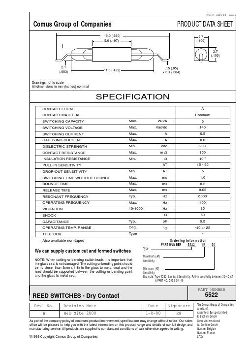
16.0 (.630) 5.0 (.197)
PRODUCT DATA SHEET
2.7 (.106) 2.7 (.106)
2.1 (.083) Drawings not to scale All dimensions in mm (inches) nominal
11.0 (.433)
.15 (.05) x 0.1 (.004)
SPECIFICATION
CONTACT FORM CONTACT MATERIAL SWITCHING CAPACITY SWITCHING VOLTAGE SWITCHING CURRENT CARRYING CURRENT DIELECTRIC STRENGTH CONTACT RESISTANCE INSULATION RESISTANCE PULL-IN SENSITIVITY DROP-OUT SENSITIVITY SWITCHING TIME WITHOUT BOUNCE BOUNCE TIME RELEASE TIME RESONANT FREQUENCY OPERATING FREQUENCY VIBRATION SHOCK CAPACITANCE OPERATING TEMP. RANGE TEST COIL Also available non-taped Typ. Deg. Type Min. Max. Max. Max. Typ. Max. 10-1000 Max. Max. Max. Max. Min. Max. Min. W/VA Vac/dc A A Vdc mΩ Ω AT AT ms ms ms Hz Hz Hz G pF ˚C A Rhodium 6 140 0.5 0.8 200 150 1010 15 - 50 5 1.0 0.3 0.05 6000 400 35 50 0.5 -40 +125 Ordering Information PART NUMBER 5522 15 Type Maximum (AT) Sensitivity Minimum (AT) Sensitivity Example: Type 5522 Standard Sensitivity. Pull-in sensitivity between 30-40 AT is PART NO. 5522 30 40 50
MAX232中文资料(官方版)
新一代 器件特性 ____________________________
♦ 对于低电压、集成 ESD 保护的应用 MAX3222E/MAX3232E/MAX3237E/MAX3241E/ MAX3246E:+3.0V 至 +5.5V、低功耗、速率高达 1Mbps、利用四个 0.1µF 电容实现真正的 RS-232 收发器 (MAX3246E 提供 UCSPTM 封装 )。 ♦ 对于低成本应用 MAX221E:±15kV ESD 保护、+5V、1µA、 具有 AutoShutdownTM 功能的单芯片 RS-232。
________________________________ 应用
便携式计算机 低功耗调制解调器 接口转换 电池供电 RS-232 系统 多点 RS-232 网络
_____________________________ 定购信息
PART MAX220CPE MAX220CSE MAX220CWE MAX220C/D MAX220EPE MAX220ESE MAX220EWE MAX220EJE MAX220MJE TEMP RANGE 0°C to +70°C 0°C to +70°C 0°C to +70°C 0°C to +70°C -40°C to +85°C -40°C to +85°C -40°C to +85°C -40°C to +85°C -55°C to +125°C PIN-PACKAGE 16 Plastic DIP 16 Narrow SO 16 Wide SO Dice* 16 Plastic DIP 16 Narrow SO 16 Wide SO 16 CERDIP 16 CERDIP
ZMM55C6V2中文资料(secos)中文数据手册「EasyDatasheet - 矽搜」

5.8 6.2 6.6
6.4 6.8 7.2
7.0 7.5 7.9
7.7 8.2 8.7
8.5 9.1 9.6
9.4 10 10.6
10.4 11 11.6
11.4 12 12.7
12.4 13 14.1
13.8 15 15.8
15.3 16 17.1
16.8 18 19.1
18.8 20 21.2
5
15
70
1.0
5
20
70
1.0
5
20
90
1.0
5
26
110
1.0
5
30
110
1.0
5
40
170
1.0
5
50
170
1.0
5
55
220
1.0
5
55
220
1.0
5
80
220
1.0
5
80
220
1.0
5
80
220
1.0
5
80
220
1.0
5
80
220
1.0
2.5
90
500
1.0
2.5
90
600
1.0
2.5
110
符号
Min.
热阻Junctiobn到环境空气
RθJA
-
正向电压@I
F=200mA
VF
-
*有效规定,导致在从情况下,距离为10mm防护持在环境温度下
Typ. Max. Unit
-
0.3 * K /毫瓦
-
1.0
OPAx22x 运算放大器说明书
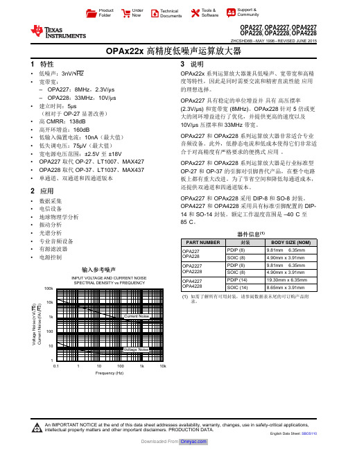
0.11011001k10k100k10k1k100101V o l t a g e N o i s e (n V /√H z )C u r r e n t N o i s e (f A /√H z )Frequency (Hz)INPUT VOLTAGE AND CURRENT NOISE SPECTRAL DENSITY vs FREQUENCYProduct Folder Order Now Technical Documents Tools &SoftwareSupport &CommunityOPA227,OPA2227,OPA4227OPA228,OPA2228,OPA4228ZHCSHD8B –MAY 1998–REVISED JUNE 2015OPAx22x 高精度低噪声运算放大器1特性•低噪声:3nV/√Hz •宽带宽:–OPA227:8MHz ,2.3V/μs –OPA228:33MHz ,10V/μs •建立时间:5μs(相对于OP-27显著改善)•高CMRR :138dB •高开环增益:160dB•低输入偏置电流:10nA (最大值)•低失调电压:75µV (最大值)•宽电源电压范围:±2.5V 至±18V•OPA227取代OP-27、LT1007、MAX427•OPA228取代OP-37、LT1037、MAX437•单通道、双通道和四通道版本2应用•数据采集•电信设备•地球物理学分析•振动分析•光谱分析•专业音频设备•有源滤波器•电源控制输入参考噪声3说明OPAx22x 系列运算放大器兼具低噪声、宽带宽和高精度等特性,因此是同时需要交流和精密直流性能应用的理想选择。
OPAx227具有稳定的单位增益并具有高压摆率(2.3V/µs)和宽带宽(8MHz)。
OPAx228针对5倍或更大的闭环增益进行了优化,并提供更高的速度以及10V/µs 压摆率和33MHz 带宽。
Altium Designer 22(中文版)电子设计速成实

1.4.1虚拟BOM条目 1.4.2独立注释
2.1 Altium 1
Designer 22 的系统配置要 求及安装
2.2 Altium 2
Designer 22 的激活
3 2.3 Altium
Designer 22 的操作环境
4
2.4常用系统 参数的设置
5
2.5原理图系 统参数的设置
1
2.6 PCB系统 参数的设置
10.3.1阻抗计算的必要性 10.3.2常见的阻抗模型 10.3.3阻抗计算详解 10.3.4阻抗计算实例
10.4.1扇孔推荐及缺陷做法 10.4.2 BGA扇孔 10.4.3扇孔的拉线
10.5.1鼠线的打开与关闭 10.5.2 PCB网络的管理与添加 10.5.3网络及网络类的颜色管理 10.5.4层的管理 10.5.5元素的显示与隐藏 10.5.6特殊粘贴法的使用 10.5.7多条走线 10.5.8泪滴的作用与添加
本书以2022年正式发布的全新Altium Designer 22电子设计工具为基础,全面兼容18、19、20、21各版本。 本书以图文实战步骤形式编写,力求读者学完就能用。全书共16章,系统地介绍了Altium Designer 22全新功 能、Altium Designer 22软件及电子设计概述、工程的组成及完整工程的创建、元件库开发环境及设计、原理 图开发环境及设计、PCB库开发环境及设计、PCB设计开发环境及快捷键、流程化设计(PCB前期处理、PCB布局、 PCB布线)、PCB的DRC与生产输出、Altium Designer高级设计技巧及应用、2层最小系统板的设计、4层智能车 主板的PCB设计、RK3288平板电脑的设计、常见问题解答集锦。本书以实战的方式进行图文描述,实例丰富、内 容翔实、条理清晰、通俗易懂,最后部分详细介绍3个实战案例,让读者将理论与实践相结合,先易后难,不断深 入,适合读者各个阶段的学习和操作。全书采用了汉化的中文版本进行讲解,目的在于使读者学完本书后,按照 操作方法就能设计出自己想要的电子图纸。本书可作为高等院校电子信息类专业的教学用书,还可作为大学生课 外电子制作、电子设计竞赛的实用参考书与培训教材,并可作为广大电子设计工作者快速入门及进阶的参考用书。 随书赠送了25小时以上的配套实战操作教学视频和教学PPT,可以在本书封底扫描二维码或者进入PCB联盟网直接 获取链接下载学习。
FHD LED 电视 CX22A22DC 说明书

Connecting the Stand
When placing TV on at surface, be careful not to push, scratch, or otherwise damage the front of the TV and LCD screen. Using a phillips-head screwdriver, tighten the screws by hand. Using a power drill could damage the TV stand.
3
Mounting the TV on a wall
If you mount this TV on the wall, follow the instructions exactly as set out by the manufacturer. Incomplete or improper installation may cause injury to you, and/or damage to the LED TV. When you have appropriate wall mount brackets, please install them by using the VESA screws included in TV PE bag.
Main Menu Operation Setup Wizard . . . . . . . . . . . . . . . . . . . . . . . . . . . . . . . . . . . . . . . . . . . . . . . . . . . . . . . . . . . . . . . . . . . . . . . . . . . . . . . . . . . . . 8 Setup Menu . . . . . . . . . . . . . . . . . . . . . . . . . . . . . . . . . . . . . . . . . . . . . . . . . . . . . . . . . . . . . . . . . . . . . . . . . . . . . . . . . . . . . 10 Picture Menu . . . . . . . . . . . . . . . . . . . . . . . . . . . . . . . . . . . . . . . . . . . . . . . . . . . . . . . . . . . . . . . .. . . . . . . . . . . . . . . . . . . . 11 Sound Menu . . . . . . . . . . . . . . . . . . . . . . . . . . . . . . . . . . . . . . . . . . . . . . . . . . . . . . . . . . . . . . . . . . . . . . . . . . . . . . . . . . . . 12 Time Menu . . . . . . . . . . . . . . . . . . . . . . . . . . . . . . . . . . . . . . . . . . . . . . . . . . . . . . . . . . . . . . . . . . . . . . . . . . . . . . . . . . . . . 13 Lock Menu . . . . . . . . . . . . . . . . . . . . . . . . . . . . . . . . . . . . . . . . . . . . . . . . . . . . . . . . . . . . . . . . . . . . . . . . . . . . . . . . . . . . . 14 Channel Menu . . . . . . . . . . . . . . . . . . . . . . . . . . . . . . . . . . . . . . . . . . . . . . . . . . . . . . . . . . . . . . . . . . . . . . . . . . . . . . . . . . 15 Media Menu . . . . . . . . . . . . . . . . . . . . . . . . . . . . . . . . . . . . . . . . . . . . . . . . . . . . . . . . . . . . . . . . . . . . . . . . . . . . . . . . . . . . . 16
海杰 CX1-22R 可编程控制器 说明书
海杰CX1-22R可编程控制器 CX1-22R Programmable Controller用户手册User Reference ManualPLC。
它是为满足市场对22路以下低价格、高性能PLC的需求设计的,同时还具有扩展功能。
可灵活运用在各种工业自动控制场合,如冶金、化工、塑料、轻纺、食品、包装等行业中的生产机械、工业流水线、各种机床的工业控制设备中。
它为用户提供了采用传统的梯形图逻辑方法以及HJ为用户定制编程方法对一个控制系统进行开发的能力。
功能介绍:▪工作电源AC85~264V▪22路I/0输入输出,其中输入12路,输出10路(继电器型)▪本机采用高性能进口工业级芯片设计,可适应高电磁干扰的工业环境▪高速运算,基本指令每步0.8uS▪输入口具有数字滤波功能从1mS到512mS可调▪2路高速外部脉冲输入计数器,计数频率2×5KHZ▪有扩展接口,可以方便地连接RS232C、模拟量输入输出、I/O等扩展模块和人机界面、变频器等外围设备▪EEPROM程序寄存器达800步,不用电池记忆,无需维护▪内部继电器192点▪定时器/计数器32点▪EEPROM数据掉电记忆▪编程语言采用梯形图▪采用循环扫描工作方式▪内置24V/200mA直流电源,可供外围设备使用,如接近传感器等其它元件▪一体化紧凑型设计,长×宽×高为98×90×82▪容易安装,使用DIN导轨或便利的固定孔安装表1-1为CX1型PLC 的内部寄存及I/O 配置情况。
表1-1:内部寄存及I/O 配置功 能数据类型 编号(地址) 数量X(bit) X0~X3F 64 输入继电器用来存储外部开关信号 WX(word) WX0~WX3 4 Y(bit) Y0~Y3F 64 I/O 继 电 器 输出继电器用来存储程序运行结果并输出 WY(word) WY0~WY3 4 M(bit) M0~M11F 192 通用内部继电器只能在PLC 内部使用,不能用于输出 WM(word) WM0~WM1112内 部 继 电 器 特殊内部继电器具有特殊用途的内部继电器,具体用途见附录1M(bit) M8000~M803F 64定时器触点定时时间到,触点动作,触点序号与定时器相同T(bit) T0~T31 32计数器触点计数完毕触点动作,触点序号与计数器相同 C(bit) C0~C31 32 定 时 器 / 计 数 器 定时器/计数器经过值寄存器用来存储定时器/计数器的经过值,寄存器的序号与定时器/计数器的序号一一对应 WEV(word) WEV0~EV3132通用数据寄存器用来存储PLC 内部处理的数据WD(word) WD0~WD31 32数 据 区 特殊数据寄存器具有特殊用途的内部寄存器,具体用途见附录2WD(word) WD8000~WD8015 1616bit (word) 十进制常数(整数)范围:16bit(K0~K65535)32bit(K-2147483648~K2147483647)K 32bit (2word)16bit (word) 常 数十六进制常数(整数)范围:16bit(H0~HFFFF)32bit(H0~HFFFFFFFF)H32bit (2word)表中X 和Y 分别表示输入、输出继电器,它们以位(bit )寻址,而WX 和WY 则是以字(word )寻址的输入、输出继电器(或称为输入、输出寄存器)。
奥林巴斯C22

奥林巴斯CX22
参数规格
光学参数
观察头双目观察筒,镜筒倾角为30°,瞳间距48-75mm,眼点调整:377.8 - 427.7毫米目镜视场数F.N. 20(防霉处理)
物镜固定4孔物镜转盘
平场消色差
4× N.A.0.1, W.D. 18.5mm
10× N.A.0.25 W.D. 10.5mm
40× N.A.0.65 W.D. 0.56mm
100× N.A.1.25 W.D. 0.13mm(仅CX22LEDRFS1/CX22RFS1)
调焦载物台垂直运动微调最小距离2.5微米
聚光镜阿贝聚光镜,数值孔径1.25(浸油时),内装式孔径光阑
微调范围微调最小距离2.5微米
粗调范围粗调行程每一圈为20mm
照明系统内置透射光柯勒照明,6V20W卤素灯 100-240V 50/60Hz通用
其他参数额定电压/电流:AC 100–120/220–240 V 50/60 Hz 0.42/0.25 A 耗电量:18.5W
主要参数
光学系统UIS2光学系统(无限远校正系统)
载物台钢丝传动,尺寸为120mm×132mm,活动范围为X轴向76mm × Y轴向30mm,单片标本夹
产品附件反光镜,15×目镜(F.N.12,防霉处理),电缆支架,木储存箱(264(宽)×305(长)×474(高)),测微尺,箭头指示器,滤光片托盘,暗场光阑
产品重量6Kg。
(完整word版)MCM-22文献非常实用哦

文献综述0.前言1990年,MOBIL公司首次报道了MCM-22分子筛的合成,由于MCM—22分子筛含有12元环和10元环两种孔道体系,以及它作为催化剂的载体具有良好的水热稳定性,较大的孔结构,比表面积和微孔容积,已引起了国内外研究者的极大关注。
MCM—22分子筛在催化裂化,异构化,甲烷无氧芳构化,苯与短链烯烃烷基化有着广泛的应用前景。
1.MCM—22分子筛的结构特性MCM—22分子筛拥有两套互不相通的多维孔道体系(如图1)。
一套为二维正弦孔道,有效孔径为(0。
4nm×0。
59nm),另一套是由含有十二元环的超笼(0。
71nm×0。
71nm×1。
82nm)组成,其开口也为十元环。
MCM—22分子筛较同样是十二元环的β沸石(线性通道孔径约0.57nm×0。
75nm,非线性曲折通道孔径约0。
56nm×0.65nm)略小。
因而MCM-22分子筛对于某些反应具有更好的选择性,如在苯与乙烯、丙烯烷基化反应生产苯乙烯、异丙苯时,其中副产物二乙苯、二异丙苯由于在MCM—22分子筛的十元环孔道中受阻,而有较高的选择性。
MCM-22分子筛较十元环的ZSM—5有更大的孔容,当有较多支链的烃异构体参加反应时,其进入ZSM-5十元环孔道是受阻的,然而MCM-22分子筛的十二元环孔道对多支链化合物是畅通的,会有较多的I—C5生成,此外,对不同分子的扩散性质的差别也体现了它的择形性。
2.MCM—22分子筛的一般物化性能通过对MCM-22分子筛的结构物性测定表明,N2吸附等温线的形状表现为LangmuirⅡ型,用ASAP-200静态容量法低温吸氮装置,测定MCM-22、Beta、ZSM-5分子筛的孔结构数据如表1所示。
表1 催化剂的孔结构结构特性aSi/BET面积微孔面积孔体积微孔体积晶胞大小bAl mol m2/gm2/g cm3/g cm3/gμmMCM—22504613550.520。
OMEGA FC-21和FC-22流计算机产品说明书

Air Velocity Indicators, Doppler Flowmeters, Level Measurement, Magnetic Flowmeters, Mass Flowmeters, Pitot Tubes, Pumps, Rotameters, Turbine and Paddle Wheel Flowmeters, Ultrasonic Flowmeters, Valves, Variable Area Flowmeters, Vortex Shedding Flowmeters
ߜ Custody Transfer with Audit Trail
ߜ Liquid, Gas, Steam, and Heat Flow Equations
ߜ Menu-Selectable Inputs/Outputs
ߜ Isolated Pulse and Analog Outputs
ߜ RS232 Communications with Windows Setup Software
These versatile instruments are programmable from the front panel. During setup, the user can assign inputs and outputs. For example, the isolated analog output can monitor the volume flow, corrected-volume flow, mass flow, temperature, pressure, or density. The RS232 serial port allows for data logging, transaction printing, or connection to a modem for remote meter reading.
- 1、下载文档前请自行甄别文档内容的完整性,平台不提供额外的编辑、内容补充、找答案等附加服务。
- 2、"仅部分预览"的文档,不可在线预览部分如存在完整性等问题,可反馈申请退款(可完整预览的文档不适用该条件!)。
- 3、如文档侵犯您的权益,请联系客服反馈,我们会尽快为您处理(人工客服工作时间:9:00-18:30)。
32
IXYS reserves the right to change limits, test conditions and dimensions
Phase Control Thyristors
Electrically Isolated Tab V RSM V RRM Type
V DSM V DRM V V 800 800CS 22-08io1M 1200
1200
CS 22-12io1M
Symbol Conditions
Maximum Ratings
I T(AV)M T C = 85°C 180° sine ①16A T A = 25°C 180° sine ② 2.5A I TSM
T VJ = 45°C t = 10 ms (50 Hz), sine 300A V R = 0 V t = 8.3 ms (60 Hz), sine 340A T VJ = T VJM t = 10 ms (50 Hz), sine 250A V R = 0 V
t = 8.3 ms (60 Hz), sine 285A I 2t
T VJ = 45°C t = 10 ms (50 Hz), sine 450A 2s V R = 0 V t = 8.3 ms (60 Hz), sine 480A 2s T VJ = T VJM t = 10 ms (50 Hz), sine 300A 2s V R = 0 V
t = 8.3 ms (60 Hz), sine
337A 2s (di/dt)cr
T VJ = T VJM repetitive, I T = 20 A 150
A/µs
f = 50Hz, t P = 200µs V D = 2/3 V DRM I G = 0.08 A non repetitive, I T = I T(AV)M 500A/µs di G /dt = 0.08 A/µs
(dv/dt)cr T VJ = T VJM , V DR = 2/3 V DRM
1000V/µs R GK = ∞, method 1 (linear voltage rise)P GM T VJ = T VJM t P = 30 µs 10W I T = I T(AV)M
t P = 300 µs
5W P GAV 0.5W V RGM 10
V T VJ -40...+150
°C T VJM 150°C T stg -40...+125
°C M d
Mounting torque M 3 or UNC 4-400.5-0.8
Nm Weight
3
g
Features
•Thyristor for frequencies up to 400Hz •International standard package •Epoxy meets UL 94V-0
•High performance glass passivated chip •Long-term stability of leakage current and blocking voltage
•Plasitc overmolded tab for electrical isolation Applications
•Motor control •Power converter •AC power controller
•Light and temperature control
•SCR for inrush current limiting in power supplies or AC drive Advantages
•Space and weight savings •Simple mounting
A
C
G
V RRM = 800-1200 V I T(AV)M = 16 A
A = Anode, C = Cathode, G = Gate Tab = Isolated
0 Isolated
A A
C ① mounted on heatsink Data according to IEC 60747
② without heatsink
32
IXYS reserves the right to change limits, test conditions and dimensions
Symbol Conditions
Characteristic Values
I R , I D T VJ = T VJM , V R = V RRM , V D = V DRM ≤5mA V T I T
= 30 A, T VJ = 25°C
≤
1.5V V T0For power-loss calculations only (T VJ = 150°C)0.9V r T 18
m ΩV GT V D = 6 V T VJ = 25°C ≤ 1.5V T VJ = -40°C ≤ 2.5V I GT V D = 6 V
T VJ = 25°C ≤30mA T VJ = -40°C
≤50mA V GD T VJ = T VJM , V D = 2/3 V DRM
≤0.2V I GD ≤3mA I L T VJ = 25°C, t P = 10 µs
≤100mA I G = 0.08 A, di G /dt = 0.08 A/µs I H T VJ = 25°C, V D = 6 V, R GK =
∞≤80mA t gd T VJ = 25°C, V D = ½ V DRM
≤
2µs I G = 0.08 A, di G /dt = 0.08 A/µs R thJC DC current 2.5K/W R thCH DC current 0.5K/W R thJA DC current
50K/W a
Max. acceleration, 50 Hz
50
m/s 2
Package Outline。
