SIMATIC S7-1200 可编程控制器系统手册 2011 年 4 月版的更新版
西门子 SIMATIC S7-200可编程控制器 系统手册
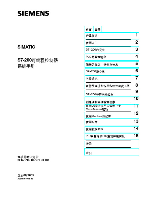
索引S7-200可编程控制器系统手册SIMATIC版本08/2005A5E00307992--02本手册的订货号:6ES7298--8FA24--8FH0安全指南本手册包括了保证人身安全与保护本产品及连接的设备应遵守的注意事项。
这些注意事项在手册中以警告三角形加以突出,并按照危险等级标明如下:危险表示如果不采取适当的预防措施,将导致死亡或者严重的人身伤害。
警告表示如果不采取适当的预防措施,将有导致死亡或严重人身伤害的可能。
小心表示如果不采取适当的预防措施将有导致轻微的人身伤害的可能。
小心表示如果不采取适当的预防措施将有导致财产损失的可能。
注意表示如果不采取适当的预防措施,有可能导致不希望的结果或状态。
合格人员只有合格人员才允许安装和操作设备。
合格人员是指被授权按照既定安全惯例和标准,对线路、设备和系统进行调试,接地和加标识的人员。
正确应用注意如下:警告该设备及其部件只能用于产品目录或者技术说明中所描述的范畴,并且只能与Siemens公司认可或者推荐的第三方厂家出产的设备或部件一起使用。
只有正确地运输、保管、配置和安装,并且按照推荐的方式操作和维护,产品才能正常、安全地运行。
注册商标SIMATIC R、SIMATIC HMI R和SIMATIC NET R是SIEMENS AG的注册商标。
本文档中的其它一些标志也是注册商标;若第三方擅自使用这些标志,可能会造成侵权。
前言本手册的用途S7--200系列小型PLC(Micro PLC)可应用于各种自动化系统。
紧凑的结构、低廉的成本以及功能强大的指令集使得S7--200PLC成为各种小型控制任务理想的解决方案。
S7--200产品的多样化以及基于Windows的编程工具,使您能够更加灵活地完成自动化任务。
本手册专为具有一定PLC背景知识的工程人员、编程人员、安装人员及电气人员编写,其内容涵盖了S7--200系列小型PLC的安装和编程信息。
阅读本手册所需的基本知识如果具备了一定的自动化知识和PLC知识,那么您将能更好地理解本手册的内容。
西门子S7-1200-PROFIBUS-CM-1242-5操作说明
1.4
运行要求............................................................................................................................... 8
1.5
PROFIBUS 组态示例............................................................................................................ 9
合格的专业人员
本文件所属的产品/系统只允许由符合各项工作要求的合格人员进行操作。其操作必须遵照各自附带的文件说明,特 别是其中的安全及警告提示。 由于具备相关培训及经验,合格人员可以察觉本产品/系统的风险,并避免可能的危 险。
Siemens 产品
请注意下列说明:
商标 责任免除
警告 Siemens 产品只允许用于目录和相关技术文件中规定的使用情况。如果要使用其他公司的产品和组件,必须得到 Siemens 推荐和允许。正确的运输、储存、组装、装配、安装、调试、操作和维护是产品安全、正常运行的前 提。必须保证允许的环境条件。必须注意相关文件中的提示。
5.2 5.2.1 5.2.2 5.2.3 5.2.4 5.2.5
诊断 .................................................................................................................................... 25 诊断方法............................................................................................................................. 25 DP 从站诊断....................................................................................................................... 26 标准诊断............................................................................................................................. 28 DP-V1 中的设备特定诊断 ................................................................................................... 30 DP-V0 中的设备特定诊断 ................................................................................................... 34
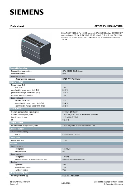
SIMATIC S7-1200 CPU 1215C 产品说明书
6ES7215-1HG40-0XB0
SIMATIC S7-1200, CPU 1215C, compact CPU, DC/DC/relay, 2 PROFINET ports, onboard I/O: 14 DI 24 V DC; 10 DO relay 2 A, 2 AI 0-10 V DC, 2 AO 0-20 mA DC, Power supply: DC 20.4-28.8 V DC, Program/data memory 125 KB
Digital outputs Number of digital outputs Switching capacity of the outputs ● with resistive load, max. ● on lamp load, max. Output delay with resistive load ● "0" to "1", max. ● "1" to "0", max. Relay outputs ● Number of relay outputs ● Number of operating cycles, max. Cable length
Single phase: 3 @ 100 kHz & 3 @ 30 kHz, differential: 3 @ 80 kHz & 3 @ 30 kHz
500 m; 50 m for technological functions 300 m; for technological functions: No
6ES72151HG400XB0 Page 2/6
1.7 µs; / instruction 2.3 µs; / instruction
S71200PLC编程及应用第4版课件第3章

6.定时器线圈指令 两条运输带顺序相连,按下起动按钮I0.3,1号运输带开始运行,8s后2号运 输带自动起动。按了停止按钮I0.2,先停2号运输带,8s后停1号运输带。 在运输带控制程序中设置了一个用起动、停止按钮控制的M2.3,用它来控 制TON的IN输入端和TOF线圈。
中间标有TOF的线圈上面是定时器的背景数据块,下面是时间预设值PT。 TOF线圈和TOF方框定时器指令的功能相同。
2.接通延时定时器 接通延时定时器TON用于将Q输出的置位操作,延时参数PT指定的一段时 间。在IN输入的上升沿开始定时。ET大于等于PT指定的设定值时,输出Q变 为1状态,ET保持不变(见波形A)。 IN输入电路断开时,定时器被复位,当前时间被清零,输出Q变为0状态。 如果IN输入信号在未达到PT设定的时间时变为0状态(见波形B),输出Q保 持0状态不变。 I0.3为1状态时,定时器复位线圈RT通电(见波形C),定时器被复位,当 前时间被清零,Q输出变为0状态。复位输入I0.3变为0状态时,如果IN输入信 号为1状态,将开始重新定时(见波形D)。
【例3-2】 用接通延时定时器设计周期和占空比可调的振荡电路。 图3-22中的串联电路接通后,定时器T5的IN输入信号为1状态,开始定时。 2s后定时时间到,它的Q输出使定时器T6开始定时,同时Q0.7的线圈通电。 3s后T6的定时时间到,它的输出“T6”.Q的常闭触点断开,使T5的IN输入电路 断开,其Q输出变为0状态,使Q0.7和定时器T6的Q输出也变为0状态。下一个 扫描周期因为“T6”.Q的常闭触点接通,T5又开始定时。Q0.7的线圈将这样周 期性地通电和断电,直到串联电路断开。Q0.7线圈通电和断电的时间分别等 于T6和T5的预设值。 【例3-3】 用3种定时器设计卫生间冲水控制电路。I0.7是光电开关检测到的 有使用者的信号,用Q1.0控制冲水电磁阀。
S7-1200 可编程控制器 系统手册说明书

通信11 S7-1200 可实现 CPU 与编程设备、HMI 和其它 CPU 之间的多种通信。
警告PROFINETPROFINET 用于使用用户程序通过以太网与其它通信伙伴交换数据:●在 S7-1200 中,PROFINET 支持 16 个最多具有 256 个子模块的 IO设备,PROFIBUS 允许使用 3 个独立的 PROFIBUS DP 主站,每个 DP 主站支持 32个从站,每个 DP 主站最多具有 512 个模块。
●S7 通信●用户数据报协议 (UDP)●ISO on TCP (RFC 1006)●传输控制协议 (TCP)通信PROFINET IO 控制器作为采用 PROFINET IO 的 IO 控制器,CPU 可与本地 PN 网络上或通过 PN/PN耦合器(连接器)连接的最多 PROFIBUS和PROFIBUSPROFIBUS 用于使用用户程序通过 PROFIBUS 网络与其它通信伙伴交换数据:●借助 CM 1242-5,CPU 作为 PROFIBUS DP 从站运行。
●借助 CM 1243-5,CPU 作为 1 类 PROFIBUS DP 主站运行。
●PROFIBUS DP 从站、PROFIBUS DP 主站和 AS-i(左侧 3 个通信模块)以及PROFINET 均采用单独的通信网络,不会相互制约。
AS-i通过 S7-1200 CM 1243-2 AS-i 主站可将 AS-i 网络连接到 S7-1200 CPU。
CPU 至 CPU S7 通信您可以创建与伙伴站的通信连接并使用 GET 和 PUT 指令与 S7 CPU 进行通信。
TeleService 通信在通过 GPRS 的 TeleService 中,安装了 STEP 7 的工程师站通过 GSM 网络 Internet和与具有 CP 1242-7 的 SIMATIC S7-1200 站进行通信。
该连接通过用作中介并连接到Internet 的远程控制服务器运行。
可编程控制器应用技术项目式教程(西门子S7-1200) 教案全套 项目1--13 西门子S7-120
教案项目一:西门子S7-1200P1C的初步认识(任务一、任务二)教案项目一:西门子S7-1200P1C的初步认识(任务三、实训1)教案教学过程设计教案教学过程设计教案教学过程设计教案教学过程设计教案教学过程设计教案教学过程设计教案教学过程设计6教学过程问题记录教案教学过程设计教案教学过程设计教案教学过程设计教案教学过程设计教案教学过程设计教案教学过程设计教案教学过程设计教案项目7:指示灯的顺序延时点亮授课章节名称任务一:指示灯闪烁控制系统设计更新、补(脉冲定时器TP)充、系统存储器与时钟存储器的知识教学过程设计教案教学过程设计让学生在编程调试过程中,思考以下几个问题:(1)TP+TP组合时:将输出Q0.0接在T1Q和接在T2.Q上时,闪烁情况有何不同?(2) TON+TP组合时:输出Q0.0是否可以接在TP的输出端或者TON的输出端,结果如何?(3) TON+TOF组合时:ToN和TOF在程序中的先后顺序对控制功能有无影响,什么影响?教案教学过程设计6 教学过程问题记录加计数器使用时,对于复位R引脚,学生运用不够灵活和熟练。
教案教学过程设计项目8:运料小车自动往返控制系统的设计(任务二)教案教学过程设计教案教学过程设计教案教学过程设计教案教学过程设计6 教学过程问题记录通过本次训练,学生对顺序功能图有了较好的认识,能够自主完成并调试成功的小组数较多。
教案。
西门子S7-1200系统手册

目录
前言 ..................................................................................................................................................3
本手册提供了有关 S7-1200 PLC 的安装和编程信息,其主要用户是具备可编程逻辑控制 器基本知识的工程师、编程人员、安装人员和电工人员。
所需的基本知识 要理解本手册,需要具备自动化和可编程逻辑控制器的基本知识。
手册适用范围
本手册适用于 STEP 7 Basic V10.5 和 S7-1200 产品系列。 有关本手册中所述 S7-1200 产品的完整列表,请参见技术规范 (页 321)。
危险 表示如果不采取相应的小心措施,将会导致死亡或者严重的人身伤害。
警告 表示如果不采取相应的小心措施,可能导致死亡或者严重的人身伤害。
小心 带有警告三角,表示如果不采取相应的小心措施,可能导致轻微的人身伤害。
小心 不带警告三角,表示如果不采取相应的小心措施,可能导致财产损失。
注意 表示如果不注意相应的提示,可能会出现不希望的结果或状态。
11/2009
A5E02486685-02
购买相关产品联系重庆艾利顿自动化 余经理 联系电话:18280227007
法律资讯
法警告律提资示讯系统
为了您的人身安全以及避免财产损失,必须注意本手册中的提示。人身安全的提示用一个警告三角表示,仅与财产 损失有关的提示不带警告三角。警告提示根据危险等级由高到低如下表示。
证书、CE 标签、C 标记和其它标准 请参见技术规范 (页 321)以获取更多信息。
微逻辑1200可编程控制器安装指南说明书
Publication 1762-IN011B-EN-PInstallation InstructionsSolid State 24V DC Source Output ModuleCatalog Number 1762-OB16Table of Contents Topic PageAdditional Resources 2Description 3Installation 4Mounting 5System Assembly 7Field Wiring Connections 8I/O Memory Mapping 10Specifications 11North American Hazardous Location Approval 142 Solid State 24V DC Source Output Module Publication 1762-IN011B-EN-P - June 2013Additional ResourcesIf you would like a manual, you can:•download a free electronic version from the Internet: •purchase a printed manual by contacting your local Allen-Bradley distributor or Rockwell Automation representative Publication DescriptionMicroLogix 1200 Programmable Controllers User Manual (Bulletin 1762 Controllers and Expansion I/O), publication rmation on installing, wiring, and operating a MicroLogix 1200 Programmable Controller.MicroLogix 1200 Programmable Controllers Installation Instructions, publication 1762-IN006.Installation guide for the MicroLogix 1200 Programmable Controller.Industrial Automation Wiring and Grounding Guidelines, publication 1770-4.1.More information on proper wiring and grounding techniques.Solid State 24V DC Source Output Module 3Publication 1762-IN011B-EN-P - June 2013Description Item Description Item Description1a upper panel mounting tab 5bus connector cover1b lower panel mounting tab 6flat ribbon cable with bus connector(female pins)2I/O diagnostic LEDs 7terminal block3module door with terminal identification label8DIN rail latch4bus connector with male pins 9pull loop1a64 Solid State 24V DC Source Output Module Publication 1762-IN011B-EN-P - June 2013Installation1762 I/O is suitable for use in an industrial environment when installed in accordance with these instructions. Specifically, this equipment is intended for use in clean, dry environments (Pollution degree 2(1)) and to circuits not exceeding Over Voltage Category II (2) (IEC 60664-1).(3)Prevent Electrostatic Discharge Remove Power(1)Pollution Degree 2 is an environment where, normally, only non-conductive pollution occurs except that occasionally a temporary conductivity caused by condensation shall be expected.(2)Over Voltage Category II is the load level section of the electrical distribution system. At this level transient voltages are controlled and do not exceed the impulse voltage capability of the product’s insulation.(3)Pollution Degree 2 and Over Voltage Category II are International Electrotechnical Commission (IEC) designations.Electrostatic discharge can damage integrated circuits or semiconductors if you touch bus connector pins. Follow these guidelines when you handle the module:•T ouch a grounded object to discharge static potential.•W ear an approved wrist-strap grounding device.•Do not touch the bus connector or connector pins.•Do not touch circuit components inside the module.•If available, use a static-safe work station.•When not in use, keep the module in its static-shield box.Remove power before removing or installing this module. When you remove or install a module with power applied, an electrical arc may occur. An electrical arc can cause personal injury or property damage by:•sending an erroneous signal to your system’s field devices, causing unintended machine motion•causing an explosion in a hazardous environment•causing permanent damage to the module’s circuitryElectrical arcing causes excessive wear to contacts on both the module and its mating connector. W orn contacts may create electrical resistance.Solid State 24V DC Source Output Module 5Publication 1762-IN011B-EN-P - June 2013Mounting Minimum Spacing Maintain spacing from enclosure walls, wireways, adjacent equipment, etc. Allow 50.8 mm (2 in.) of space on all sides for adequate ventilation, as shown:Do not remove protective debris strip until after the module and all other equipment near the module is mounted and wiring is complete. Once wiring is complete and the module is free of debris, carefully remove protective debris strip. Failure to remove strip before operating can cause overheating.1762 expansion I/O may be mounted horizontally only.During panel or DIN rail mounting of all devices, be sure that all debris (metal chips, wire strands, etc.) are kept from falling into the module. Debris that fall into the module could cause damage when power is applied to the module.6 Solid State 24V DC Source Output Module Publication 1762-IN011B-EN-P - June 2013DIN Rail MountingThe module can be mounted using the following DIN rails: 35 x 7.5 mm(EN 50 022 - 35 x 7.5) or 35 x 15 mm (EN 50 022 - 35 x 15).Before mounting the module on a DIN rail, close the DIN rail latch. Press the DIN rail mounting area of the module against the DIN rail. The latch will momentarily open and lock into place.Use DIN rail end anchors (Allen-Bradley part number 1492-EA35 or 1492-EAH35) for vibration or shock environments.Panel MountingUse the dimensional template shown below to mount the module. The preferred mounting method is to use two M4 or #8 panhead screws per module. M3.5 or #6 panhead screws may also be used, but a washer may be needed to ensure a good mechanical contact. Mounting screws are required on every module.For environments with greater vibration and shock concerns, use the panelmounting method described below, instead of DIN rail mounting.For more than 2 modules: (number of modules - 1) x 40 mm (1.58 in.)NOTE: All dimensions are in mm (inches). Hole spacing tolerance: ±0.4 mm (0.016 in.).Solid State 24V DC Source Output Module 7Publication 1762-IN011B-EN-P - June 2013System AssemblyThe expansion I/O module is attached to the controller or another I/O module by means of a flat ribbon cable after mounting as shown below.TIP Use the pull loop on the connector to disconnect modules. Do not pull on the ribbon cable.EXPLOSION HAZARD•In Class I, Division 2 applications, the bus connector must be fully seated and the bus connector cover must be snapped in place.•In Class I, Division 2 applications, all modules must be mounted in direct contact with each other as shown on Page 6. If DIN rail mounting is used, an end stop must be installed ahead of the controllerand after the last 1762 I/O module.8 Solid State 24V DC Source Output Module Publication 1762-IN011B-EN-P - June 2013Field Wiring ConnectionsGrounding the ModuleThis product is intended to be mounted to a well-grounded mounting surface such as a metal panel. Refer to Industrial Automation Wiring and Grounding Guidelines, Allen-Bradley publication 1770-4.1, for additional information.Output WiringBasic wiring (1) of the 1762-OB16 is shown below.A write-on label is provided with the module. Mark the identification of each terminal with permanent ink, and slide the label back into the door.(1)Surge Suppression – Connecting surge suppressors across your external inductive load will extend the life of the relay contacts. For additional details, refer to Industrial Automation Wiring and Grounding Guidelines , Allen-Bradley publication 1770-4.1.Be careful when stripping wires. Wire fragments that fall into a module could cause damage when power is applied. Once wiring is complete, ensure the module is free of all metal fragments.Solid State 24V DC Source Output Module 9Publication 1762-IN011B-EN-P - June 2013Wiring the Finger-Safe Terminal BlockWhen wiring the terminal block, keep the finger-safe cover in place.1.Route the wire under the terminal pressure plate. Y ou can use the stripped end of the wire or aspade lug. The terminals will accept a 6.35 mm (0.25 in.) spade lug.2.Tighten the terminal screw making sure the pressure plate secures the wire. Recommended torque when tightening terminal screws is 0.90 Nm(8 lb-in.).Miswiring of the module to an AC power source will damage the module.Finger-safe cover not shown for clarity.If you need to remove the finger-safe cover, insert a screw driver into one of the square wiring holes and gently pry the cover off. If you wire the terminal block with the finger-safe cover removed, you will not be able toput it back on the terminal block because the wires will be in the way.10 Solid State 24V DC Source Output Module Publication 1762-IN011B-EN-P - June 2013Wire Size and Terminal Screw TorqueEach terminal accepts up to two wires with the following restrictions:I/O Memory MappingOutput Data FileFor each output module, the output data file contains the controller-directed state of the discrete output points. Bit positions 0…15 correspond to output terminals 0…15.w = write onlyA ddressing The addressing scheme for 1762 Expansion I/O is shown below.(1)I/O located on the controller (embedded I/O) is slot 0. I/O added to the controller (expansion I/O) begins with slot 1.Wire Type Wire Size Terminal Screw Torque Solid Cu-90 °C (194 °F)#14…22 AWG 0.90 Nm (8 lb-in.)Stranded Cu-90 °C (194 °F)#16…22 AWG 0.90 Nm (8 lb-in.)W o rd Bit Position 15141312111098765432100w w w w w w w w w w w w w w w w O0:x.0/0OutputData File Slot Number (1)Word (always zero for this module)Bit (0…15)Bit DelimiterWord DelimiterSlot DelimiterSolid State 24V DC Source Output Module 11Publication 1762-IN011B-EN-P - June 2013SpecificationsGeneral Specifications Specification ValueDimensions, HxWxD 90 x 40.4 x 87 mm (height including mounting tabs is 110 mm)3.54 x 1.59 x 3.43 in. (height including mounting tabs is4.33 in.)Approximate Shipping Weight (with carton)235 g (0.52 lbs.)Temperature, nonoperating -40…85 °C (-40…185 °F)Temperature, operating 0…55 °C (32…131 °F)Humidity, operating 5…95% non-condensingAltitude, operating 2000 m (6561 ft)Vibration, operating 10…500 Hz, 5 g, 0.030 in. max. peak-to-peak, 2 hours per axis Shock Operating: 30 g panel mounted, 3 pulses per axisNon-Operating: 50 g panel mounted, 3 pulses per axis (40 g DIN Rail mounted)Hazardous Environment Class Class I, Division 2, Hazardous Location, Groups A, B, C, D ISA/ANSI 12.12.01(C-UL under CSA C22.2 No. 213)Radiated and Conducted Emissions EN50081-2 Class AESD Immunity (IEC1000-4-2) 4 kV contact, 8 kV air, 4 kV indirectRadiated Immunity (IEC1000-4-3)10 V/m, 80…1000 MHz, 80% amplitude modulation, +900 MHz keyed carrierFast Transient Burst (IEC1000-4-4) 2 kV, 5 kHzSurge Immunity (IEC1000-4-5) 2 kV common mode, 1 kV differential modeConducted Immunity (IEC1000-4-6)10V, 0.15…80 MHz (1)(1)Conducted Immunity frequency range may be 150 kHz…30 MHz if the Radiated Immunity frequency range is 30…1000 MHz.12 Solid State 24V DC Source Output Module Publication 1762-IN011B-EN-P - June 2013Sourcing Output - Source describes the current flow between the I/O module and the field device. Sourcing output circuits supply (source) current to sinking field devices. Field devices connected to the negative side (DC Common) of the field power supply are sinking field devices. Field devices connected to the positive side (+V) of the field supply are sourcing field devices.Typical Loading Resistor - T o limit the effects of leakage current through solid-state outputs, a loading resistor can be connected in parallel with your load. Use a 5.6k ohm, 1/4 W resistor for transistor outputs, 24V DC operation.Recommended Surge Suppression - Use a 1N4004 diode reverse-wired across the load for transistor outputs switching 24V DC inductive loads. For additional information, refer to Industrial Automation Wiring and Grounding Guidelines, Allen-Bradley publication 1770-4.1.Output Specifications Specification ValueVoltage Category 24V DCOperating Voltage Range 20.4…26.4V DCNumber of Outputs 16Bus Current Draw, max 175 mA @ 5V DC (0.88 W)Heat Dissipation max 2.9 total Watts @ 30 °C (86°F)2.1 total Watts @ 55 °C (131 °F)Signal Delay (max.) – resistive load turn-on = 0.1 msturn-off = 1.0 msOff-State Leakage max 1.0 mAOn-State Current (min.) 1.0 mAOn-State Voltage Drop, max 1.0V DCContinuous Current per Point, max 0.5A @ 55 °C (131 °F)1.0A @ 30 °C (86 °F)Continuous Current per Module, max 4.0A @ 55 °C (131 °F)8.0A @ 30 °C (86 °F)Surge Current, max 2.0 A (Repeatability is once every 2 s @ 55 °C (131 °F), once every second @ 30 °C (86 °F) for a duration of 10 ms.)Power Supply Distance Rating 6 (The module may not be more than 6 modules away from the power supply.)Isolated Groups Group 1: Outputs 0 (15)Output Group to Backplane Isolation Verified by one of the following dielectric tests: 1200V AC for 1 s or 1697V DC for 1 s.75V DC working voltage (IEC Class 2 reinforced insulation)Vendor I.D. Code 1Product Type Code 7Product Code 103Solid State 24V DC Source Output Module 13Publication 1762-IN011B-EN-P - June 2013Certifications Certification (when product is marked)(1)(1)See product certification link at /products/certification for Declaration of Conformity, Certificates, and other certification details.Valuec-UL-us UL Listed Industrial Control Equipment, certified for US andCanada.UL Listed for Class I, Division 2 Group A,B,C,D HazardousLocations, certified for U.S and Canada.See UL File E334470.CE European Union 2004/108/EC EMC Directive, compliant with:EN 61326-1; Meas./Control/Lab., Industrial RequirementsEN 61000-6-2; Industrial ImmunityEN 61000-6-4; Industrial EmissionsEN 61131-2; Programmable Controllers (Clause 8, Zone A & B)C-Tick Autralian Rediocommunications Act, compliant with:AS/NZS CISPR 11; Industrial EmissionsKC Korean Registration of Broadcasting and CommunicationsEquipment, compliant with:Article 58-2 of Radio Waves Act, Clause 314 Solid State 24V DC Source Output Module Publication 1762-IN011B-EN-P - June 2013North American Hazardous Location Approval This equipment is suitable for use in Class I, Division 2, Groups A, B, C, D or non-hazardous locations only.The following W ARNING statement applies to use in hazardous locations.The following information applies when operating this equipment in hazardous locations:Informations sur l’utilisation de cet équipement en environnements dangereux:Products marked "CL I, DIV 2, GP A, B, C, D" are suitable for use in Class I Division 2 Groups A, B, C, D, Hazardous Locations and nonhazardous locations only. Each product is supplied with markings on the rating nameplate indicating the hazardous location temperature code. When combining products within a system, the most adverse temperature code (lowest "T" number) may be used to help determine the overall temperature code of the system. Combinations of equipment in your system are subject to investigation by the local Authority Having Jurisdiction at the time of installation.Les produits marqués "CL I, DIV 2, GP A, B, C, D" ne conviennent qu'à une utilisation en environnements de Classe I Division 2 Groupes A, B, C, D dangereux et non dangereux. Chaque produit est livré avec des marquages sur sa plaque d'identification qui indiquent le code de température pour les environnements dangereux. Lorsque plusieurs produits sont combinés dans un système, le code de température le plus défavorable (code de température le plus faible) peut être utilisé pour déterminer le code de température global du système. Les combinaisons d'équipements dans le système sont sujettes à inspection par les autorités locales qualifiées au moment de l'installation.EXPLOSION HAZARD •Substitution of components may impair suitability for Class I, Division 2.•Do not replace components or disconnect equipment unless power has been switched off.•Do not connect or disconnect components unless power has been switched off.•This product must be installed in an enclosure.•In Class I, Division 2 applications, the bus connector must be fully seated and the bus connector cover must be snapped in place.•In Class I, Division 2 applications, all modules must be mounted in direct contact with each other as shown on Page 6. If DIN rail mounting is used, an end stop must be installed ahead of the controller and after the last 1762 I/O module.•All wiring must comply with N.E.C. article 501-4(b).•The interior of the enclosure must be accessible only by the use of a tool.•For applicable equipment (relay modules, etc.), exposure to some chemicals may degrade the sealing properties of materials used in the following devices: Relays, Epoxy. It is recommended that the User periodically inspect these devices for any degradation of properties and replace the module if degradation is found.RISQUE D’EXPLOSION•La substitution de composants peut rendre cet équipement impropre à une utilisation en environnement de Classe 1, Division 2. •Ne pas remplacer de composants ou déconnecter l'équipement sans s'être assuré que l'alimentation est coupée. •Ne pas connecter ou déconnecter des composants sans s'être assuré que l'alimentation est coupée. •Ce produit doit être installé dans une armoire. •Pour les applications de Classe I, Division 2, le connecteur de bus doit être correctement installé et son couvercle enclenché. •Pour les applications de Classe 1, Division 2, tous les modules doivent être installés en contact direct les uns avec les autres, comme indiqué page 6. Si on utilise le montage sur rail DIN, une butée doit être placée à l'avant de l'automate et après la dernière unité d'E/S 1762.Solid State 24V DC Source Output Module 15 Notes:Publication 1762-IN011B-EN-P - June 2013Rockwell Automation SupportRockwell Automation provides technical information on the Web to assist you in using its products. At /support/, you can find technical manuals, a knowledge base of FAQs, technical and application notes, sample code and links to software service packs, and a MySupport feature that you can customize to make the best use of these tools.For an additional level of technical phone support for installation, configuration and troubleshooting, we offer TechConnect support programs. For more information, contact your local distributor or Rockwell Automation representative, or visit /support/.Installation AssistanceIf you experience a problem within the first 24 hours of installation, please review the information that's contained in this manual. You can also contact a special Customer Support number for initial help in getting your product up and running .New Product Satisfaction ReturnRockwell Automation tests all of its products to ensure that they are fully operational when shipped from the manufacturing facility. However, if your product is not functioning and needs to be returned, follow these procedures.Documentation FeedbackYour comments will help us serve your documentation needs better. If you have any suggestions on how to improve this document, complete this form, publication RA-DU002, available at /literature/.United States or Canada 1.440.646.3434Outside United States or Canada Use theWorldwide Locator at/support/americas/phone_en.html , orcontact your local Rockwell Automation representative.United States Contact your distributor. You must provide a Customer Support case number (call the phone number above to obtain one) to your distributor to complete the return process.Outside United States Please contact your local Rockwell Automation representative for the return procedure.Allen-Bradley, Rockwell Automation, MicroLogix, and T echConnect are trademarks of Rockwell Automation, Inc.Trademarks not belonging to Rockwell Automation are property of their respective companies.Publication 1762-IN011B-EN-P - June 2013Supersedes Publication 1762-IN011A-EN-P - July 2000Copyright © 2013 Rockwell Automation, Inc. All rights reserved.。
SIMATIC S7-1200 CPU 1214C 数据手册说明书

CPU 1214C DC/DC/DC V4.5
STEP 7 V17 or higher
Yes 20.4 V 28.8 V Yes
24 V 20.4 V 28.8 V
500 mA; CPU only 1 500 mA; CPU with all expansion modules 12 A; at 28.8 V 0.5 A²·s
14
24 V 5 V DC at 1 mA 15 V DC at 2.5 mA
0.2 ms, 0.4 ms, 0.8 ms, 1.6 ms, 3.2 ms, 6.4 ms and 12.8 ms, selectable in groups of four 0.2 ms 12.8 ms
Yes
Single phase: 3 @ 100 kHz & 3 @ 30 kHz, differential: 3 @ 80 kHz & 3 @ 30 kHz
2/15/2022
Subject to change without notice © Copyright Siemens
Output voltage ● for signal "0", max. ● for signal "1", min.
Output current ● for signal "1" rated value ● for signal "0" residual current, max.
Analog outputs Number of analog outputs
Analog value generation for the inputs Integration and conversion time/resolution per channel ● Resolution with overrange (bit including sign), max. ● Integration time, parameterizable ● Conversion time (per channel)
西门子工业自动化 SIMATIC S7-1200 控制器 手册

SIMATIC S7-1200以最低成本提供最大效能SIMATIC 控制器Answers for industry.2模組化. 功能強大. 方便使用.交互運作是致勝的關鍵全新的模組化 SIMATIC S7-1200 控制器,是本公司的核心產品,適用於高度精確的自動化作業。
SIMATIC HMI Basic Panel ,旨在整合這套新控制器和強大的整合型編程規劃系統,可簡化開發作業、快速啟動、進行精確監視,實現最高的可用性。
產品與其創新功能之間,緊密的整合與互動作用,使小型自動化系統帶來前所未有的超高效率。
控制器SIMATIC S7-1200 控制器是模組化,精巧而且多功能。
不僅可保障客戶的投資,也適合各種應用領域。
此控制器具備可擴充的彈性設計、符合工業通訊最高標準的通訊介面,以及全方位的強大整合性的運動控制功能,是全方位自動化解決方案的必備要素。
出眾的特色,還包括了控制器和 HMI 的共用介面、通訊,以及容易使用的整合型編程規劃系統。
新 SIMATIC S7-1200 控制器、各種 SIMATIC HMI Basic 型面板,與高度整合能力的 SIMATIC STEP 7 Basic 設計系統之間,效益斐然的交互運作,造就了獨一無二的整合性自動化解決方案,尤其適用於精巧型的控制器。
系統之間的互動為您量身打造之系統互動223414186810121620控制器人機面板軟體控制器的詳細介紹- 可擴充的彈性設計- 工業通訊- 整合的運動控制功能面板的詳細介紹軟體的詳細介紹3功能強大的組件,是自動化領域的 成功關鍵;不過,真正提供獨特優勢的,其實是所有組件的互動整合作用效益。
人機面板新增的視覺化功能,能改善小型機器或簡單應用的操作方式。
由於 SIMATIC HMI Basic 型面板提供了必要的功能,打造創新自動化解決方案的實惠途徑。
SIMATIC HMI Basic 面板附有觸控按鍵的高對比圖形化螢幕、簡易網路及通訊功能,極適合與全新的 SIMATIC S7-1200 搭配使用。
SIMATIC S7-1200 入门手册
SIMATIC S7-1200 入门手册这份入门手册提供有关SIMATIC S7-1200 PLC控制器的基础知识,例如如何安装,配置和编程。
这些说明是针对初学者设计的,允许您快速掌握该领域的基础知识。
SIMATIC S7-1200是基于SIMATIC S7系列的新一代控制器,具有现代化的硬件和软件,享有卓越的可靠性、性能和可扩展性。
它是一种高效和可靠的解决方案,适用于各种自动化控制应用。
硬件组件1. CPU –为S7-1200控制器提供处理能力,控制其他硬件部分。
2. 数字输入/输出模块(DI/DO)–用于将外部数字信号输入或输出控制器。
4. 通信模块–用于与其他设备进行通信。
5. 能源模块–为控制器提供电力。
安装在安装S7-1200之前,请确保您已经了解以下信息:1. 合适的安装位置–控制器需要在干燥和通风良好的环境下安装。
2. 适于设备的安装方法–请注意控制器的大小及其与其他设备的配合情况。
3. 识别正确的CPU –在开始安装之前,请确保您已经选择了正确的CPU,它具有您要求的处理能力及功能。
4. 连接合适的模块–根据您的需要选择数字/模拟输入输出模块和通讯模块。
配置在开始配置前,请确保您拥有以下信息:1. CPU的要求– CPU需要定义您的编程依赖(例如内存大小)。
2. 模块的要求–注意模块的数量和信号类型(数字或模拟)。
3. 通讯要求–该控制器的通讯方式必须与您的应用程序相符。
4. 能源要求–请根据您的需要选择合适的电源。
编程S7-1200编程语言包括:1. 网络–专门设计用于结构化编程,有效维护和调试大型程序。
2. 语句列表–操作简单,适用于编制小型程序。
3. 功能块–可以编制可重用的程序模块,方便模块化编程。
4. 引导程序–启动,配置和调试S7-1200的软件。
总结通过本入门手册,您应该了解了SIMATIC S7-1200控制器的基本信息。
请记得,在实际应用之前,请认真阅读相关文档,确保特定应用程序的适用性和正确性。
SIMATIC S7-1200 选型目录(201104)

28
29 29 29 30 31
32 34 38 39 3
SIMATIC S7-1200 技术综述
西门子控制器家族产品
西门子控制器系列是一个完整的产品组合,包括从高性能可编程 逻辑控制器的书本型迷你控制器 LOGO! 到基于 PC 的控制器,无论 多么苛刻的要求,它都能满足要求 — 根据具体应用需求及预算, 灵活组合、定制(系列化的控制器家族产品满足你的不同应用及 需求)。
S7-1200 可编程序控制器
产品样本 • 04.2011
SIMATIC S7-1200
Answers for industry.
41
2
S7-1200 可编程序控制器
产品样本 • 04.2011
技术综述
通信 CM1 241 通信模块 CSM 1277 紧凑型交换机模块 CM 1243-5 PROFIBUS DP 主站模块 CM 1242-5 PROFIBUS DP 从站模块 CP 1242-7 GPRS 模块 TS 模块
输入/输出扩展模块 SB(信号板) SB 1221 数字量输入信号板 SB 1222 数字量输出信号板 SB 1223 数字量输入/输出信号板 SB 1231 热电偶和热电阻模拟量输入信号板 SB 1231 模拟量输入信号板 SB 1232 模拟量输出信号板
通信板 CB1241 RS485
附件 电源模块 M1207 输入仿真器 SIM1274 存储卡
6
集成工艺
高速输入 SIMATIC S7-1200 控制器带有多达 6 个高 速计数器。其中 3 个输入为 100 kHz,3 个输入为 30 kHz,用于计数和测量。
高速输出 SIMATIC S7-1200 控制器集成了两个 100 kHz 的高速脉冲输出,用于步进电 机或伺服驱动器的速度和位置控制。 (使用 PLCopen 运动控制指令)这两个 输出都可以输出脉宽调制信号来控制电 机速度、阀位置或加热元件的占空比。
Siemens S7-1200 PLC 安装指南说明书
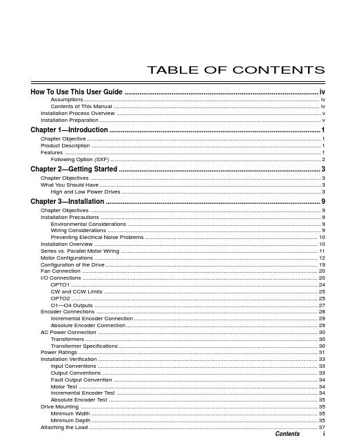
T ABLE OF CONTENTS How To Use This User Guide (iv)Assumptions (iv)Contents of This Manual (iv)Installation Process Overview (v)Installation Preparation (v)Chapter 1—Introduction (1)Chapter Objective (1)Product Description (1)Features (1)Following Option (SXF) (2)Chapter 2—Getting Started (3)Chapter Objectives (3)What You Should Have (3)High and Low Power Drives (3)Chapter 3—Installation (9)Chapter Objectives (9)Installation Precautions (9)Environmental Considerations (9)Wiring Considerations (9)Preventing Electrical Noise Problems (10)Installation Overview (10)Series vs. Parallel Motor Wiring (11)Motor Configurations (12)Configuration of the Drive (19)Fan Connection (20)I/O Connections (20)OPTO1 (24)CW and CCW Limits (25)OPTO2 (25)O1—O4 Outputs (27)Encoder Connections (28)Incremental Encoder Connection (29)Absolute Encoder Connection (29)AC Power Connection (30)Transformers (30)Transformer Specifications (30)Power Ratings (31)Installation Verification (33)Input Conventions (33)Output Conventions (33)Fault Output Convention (34)Motor Test (34)Incremental Encoder Test (34)Absolute Encoder Test (35)Drive Mounting (35)Minimum Width (35)Minimum Depth (35)Attaching the Load (37)Contents iCouplings (37)Tuning (38)Resonance (38)Mid-Range Instability (38)Tuning Procedures (38)Motor Waveforms (40)Anti-Resonance (40)Chapter 4—Application Design (41)Chapter Objectives (41)Motion Profile Application Considerations (41)Preset Mode Moves (42)Incremental Mode Preset Moves (42)Absolute Mode Preset Moves (42)Continuous Mode Moves (43)Closed Loop Operation (44)Setting Encoder Resolution (45)Encoder Step Mode (45)Motion Programs and Sequences (56)Sequence Commands (56)Creating and Executing Sequences (58)Subroutines (59)Sequence Debugging Tools (63)High-Level Programming Tools (67)Complex Branching and Looping (70)Conditionals (71)Error Flag (75)Branching Using Variables and Boolean Logic (76)Motion Profiling Mode—On-the-Fly Changes (77)Interfacing to the SX (81)Programmable Inputs and Outputs (81)PLC Operation (94)Rotary vs. Linear Indexers (97)Chapter 5—SXF Follower (99)Chapter Objectives (99)What is Following? (99)Types of Following (100)Velocity Following (100)Position and Velocity Following (103)Recede and Advance While Following (115)Synchronization (132)Other Following Features (135)Following Equation and Command Summary (137)Chapter 6—Hardware Reference (143)Chapter Objectives (143)Environmental Specifications (143)Drive Electrical Specifications (143)I/O Electrical Specifications (144)Motor Electrical Specifications (147)Operational Specifications (147)Motor Current & Torque (148)Drive Dimensions (149)Motor Dimensions (150)DIP Switch Summary (152)Non-Compumotor—Drive/Motor Connection (155)Wiring Configurations.............................................................................................................................155, 156 Terminal Connections. (157)Non-Compumotor Motors—Setting Motor Current (158)Motor Performance Specifications (158)ii SX/SXF Indexer/Driver User GuideChapter 7—Maintenance & Troubleshooting (161)Chapter Objectives (161)Maintenance (161)Battery Maintenance (161)Drive Maintenance (161)Motor Maintenance (162)Common Problems and Solutions (163)Software Debugging Tips (165)Returning the System (167)Appendices (169)Command Listing (169)SX Example Programs (171)Appendix C—LVD Installation Instructions (175)Complying with the Low Voltage Directive (LVD) (175)Additional Installation Procedures for LVD Compliance (175)Table of Graphic Symbols and Warnings (177)Index (179)Contents iiiHow To Use This User GuideThis user guide is designed to help you install, develop, and maintain your system. Each chapterbegins with a list of specific objectives that should be met after you have read the chapter. Thissection is intended to help you find and use the information in this user guide. AssumptionsThis user guide assumes that you have the skills or fundamental understanding of the followinginformation.t Basic electronics concepts (voltage, switches, current, etc.)t Basic motion control concepts (torque, velocity, distance, force, etc.)Contents of This ManualThis user guide contains the following information.Chapter 1:IntroductionThis chapter provides a description of the product and a brief account of its specific features.Chapter 2:Getting StartedThis chapter contains a detailed list of items you should have received with your SX shipment. Itwill help you to become familiar with the system and ensure that each component functions properly.Chapter 3:InstallationThis chapter provides instructions for you to properly mount the system and make all electricalconnections. Upon completion of this chapter, your system should be completely installed and readyto perform basic operations. Tuning considerations and procedures are also provided.Chapter 4:Application DesignThis chapter will help you customize the system to meet your application’s needs. Importantapplication considerations are discussed. Sample applications are provided.Chapter 5:SXF FollowerThis chapter explains the SXF Following function and the SXF’s capability to support absolute andincremental encoders.Chapter 6:Hardware ReferenceThis chapter contains information on system specifications (electrical, dimensions, and perfor-mance). It may be used as a quick-reference tool for proper switch settings and connections.Chapter 7:TroubleshootingThis chapter contains information on identifying and resolving system problems.iv SX/SXF Indexer/Driver User GuideInstallation Process OverviewTo ensure trouble-free operation, pay special attention to the environment in which the SX equip-ment will operate, the layout and mounting, and the wiring and grounding practices used. Theserecommendations are intended to help you easily and safely integrate SX equipment into yourmanufacturing facility. Industrial environments often contain conditions that may adversely affectsolid-state equipment. Electrical noise or atmospheric contamination, may also affect the SXSystem.Developing Your ApplicationBefore you attempt to develop and implement your application, there are several issues that youshould consider and address.Recognize and clarify the requirements of your application. Clearly define what you expect the system todo.Assess your resources and limitations. This will help you find the most efficient and effective means ofdeveloping and implementing your application (hardware and software).Follow the guidelines and instructions outlined in this user guide. Do not skip any steps or procedures.Proper installation and implementation can only be ensured if all procedures are completed in the propersequence.Installation PreparationBefore you attempt to install this product, you should complete the following steps:Review this entire user guide. Become familiar with the user guide’s contents so that you can quickly findthe information you need.Develop a basic understanding of all system components, their functions, and interrelationships.Complete the basic system configuration and wiring instructions (in a simulated environment, not apermanent installation) provided in Chapter 2, Getting Started.Perform as many basic functions as you can with the preliminary configuration. You can only perform thistask if you have reviewed the entire user guide. You should try to simulate the task(s) that you expect toperform when you permanently install your application (however, do not attach a load at this time). Thiswill give you a realistic preview of what to expect from the complete configuration.After you have tested all of the system’s functions and used or become familiar with tll of the system’sfeatures, carefully read Chapter 3, Installation.After you have read Chapter 3 and clearly understand what must be done to properly install the system,you should begin the installation process. Do not deviate from the sequence or installation methodsprovided.Before you begin to customize your system, check all of the systems functions and features to ensure thatyou have completed the installation process correctly.The successful completion of these steps will prevent subsequent performance problems and allowyou to isolate and resolve any potential system difficulties before they affect your system’soperation.ConventionsTo help you understand and use this user guide effectively, the conventions used throughout this userguide are explained in this section.CommandsAll commands that you are instructed to enter are shown in capital letters. The symbol >, is the SXcommand prompt. The command is displayed in boldface. A delimiter (space or carriage return) isrequired after each command. A description is provided next to each command example.Command Description>MR Sets motor resolution to 25,000 steps/revThe system ignores command syntax that is not within the valid range for a specific command. A ?prompt will be returned by the drive when the last command entered was not understood, or aparameter limit was exceeded.Contents vMotorsS Series and SX Series motors are one in the same (interchangeable terms).Warnings & CautionsWarning and caution notes alert you to possible dangers that may occur if you do not follow instruc-tions correctly. Situations that may cause bodily injury are present as warnings. Situations that maycause system damage are presented as cautions. These notes will appear in bold face and the wordwarning or caution will be centered and in all capital letters. Refer to the examples shown below:WARNINGDo not touch the motor immediately after it has been in use for an extended period of time. The motormay be hot.CAUTIONSystem damage will occur if you power up the system improperly.Related Publicationst Current Parker Compumotor Motion Control Catalogt SX Indexer/Drive Software Reference Guidevi SX/SXF Indexer/Driver User Guide。
S71200入门指南

说明
查看《S7-1200 可编程控制器系统手册》(S7-1200 Programmable Controller System Manual) 获取安全准则
本快速入门指南仅仅让用户快速了解 S7-1200 系列。在进行本指南中的练习之前,请查 看《SIMATIC S7-1200 可编程控制器系统手册》(SIMATIC S7-1200 Programmable Controller System Manual) 中的安全准则和其它信息。
有关 CPU 工作原理的基本信息 ............................................................................................ 8 每个扫描周期均执行的任务 .................................................................................................. 8 CPU 的操作模式................................................................................................................... 9 以位、字节、字等形式存储的数字数据 .............................................................................. 10 S7-1200 支持的数据类型.................................................................................................... 11 S7-1200 的存储区 .............................................................................................................. 12
SIMATIC S7-1200基本说明及应用

S7-1200 CPU描述新的模块化SIMATIC S7-1200 控制器是我们新推出产品的核心,可实现简单却高度精确的自动化任务。
SIMATIC S7-1200 控制器实现了模块化和紧凑型设计,功能强大、投资安全并且完全适合各种应用。
可扩展性强、灵活度高的设计,可实现最高标准工业通信的通信接口以及一整套强大的集成技术功能,使该控制器成为完整、全面的自动化解决方案的重要组成部分。
SIMATIC HMI 基础面板的性能经过优化,旨在与这个新控制器以及强大的集成工程组态完美兼容,可确保实现简化开发、快速启动、精确监控和最高等级的可用性。
正是这些产品之间的相互协同及其创新性的功能,帮助您将小型自动化系统的效率提升到一个前所未有的水平。
优势SIMATIC HMI 基础面板的性能经过优化,旨在与这个新控制器以及强大的集成工程组态完美兼容,可确保实现简化开发、快速启动、精确监控和最高等级的可用性。
正是这些产品之间的相互协同及其创新性的功能,帮助您将小型自动化系统的效率提升到一个前所未有的水平。
用于可扩展设计中紧凑自动化的模块化概念。
SIMATIC S7-1200 具有集成的PROFINET 接口、强大的集成技术功能和可扩展性强、灵活度高的设计。
它实现了通信简便,有效的技术任务解决方案,并完全满足一系列的独立自动化系统的应用需求。
在工程组态中实现最高效率.使用完全集成的新工程组态SIMATIC STEP 7 Basic,并借助SIMATIC WinCC Basic 对SIMATIC S7-1200 进行编程。
SIMATIC STEP 7 Basic 的设计理念是直观、易学和易用。
这种设计理念可以使您在工程组态中实现最高效率。
一些智能功能,例如直观编辑器、拖放功能和“IntelliSense”(智能感知)工具,能让您的工程进行的更加迅速。
这款新软件的体系结构源于对未来创新的不断追求,西门子在软件开发领域已经有很多年的经验,因此SIMATIC STEP 7 的设计是以未来为导向的。
S7-1200 PLC编程及应用 第4版 第7章 精简系列面板的组态与应用
4. 精简系列面板 精简系列面板主要与S7-1200配套,它适用于简单应用,有很高的性能价格 比,有功能可以定义的按键。 第二代精简面板有4.3in、7in、9in和12in的高分辨率64K色宽屏显示器,支持 垂直安装,用TIA博途组态。有一个RS-422/RS-485接口,一个RJ45以太网接口 和一个USB2.0接口。采用TFT真彩液晶屏,64K 色。RJ45以太网接口的通信速 率为10M/100M bit/s。 5.西门子的其他人机界面简介 高性能的精智系列面板有显示器为4in、7in、9in、12in和15in的按键型和触摸 型 面 板 , 还 有 22in 的 触 摸 型 面 板 。 支 持 多 种 通 信 协 议 , 有 PROFINET 、 MPI/PROFIBUS接口和USB接口。 精彩系列面板Smart Line IE是与S7-200和S7-200 SMART配套的触摸屏,有7in 和10in两种显示器,有以太网接口和RS-422/485接口。7in的Smart 700 IE具有很 高的性能价格比。 移动面板可以在不同的地点灵活应用。有7in和9in的移动面板,还有7.5in的 无线移动面板。
在HMI默认的变量表中,将变量“电动机”和“当前值”的采集周期由1s 改为100ms。单击空白行的“PLC变量”列,可以用打开的对话框将PLC变 量表中的变量传送到HMI变量表。用下拉式列表将访问模式改为“绝对访 问”。
在组态画面上的按钮时,如果使用了PLC的变量表中的变量,该变量将会 自动地添加到HMI的变量表中。
西门子Siemens S7-1200可编程控制器系统手册更新信息说明书
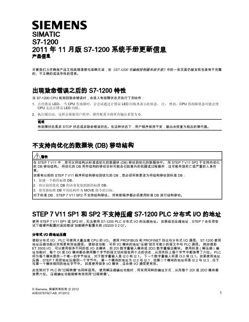
A5E03767027-AB, 07/2012
1
示例:解压缩过程映像字节 下面的示例显示解压缩“过程映像”中的一个 2DI 数字量输入模块:
“解压缩地址”。 默认情况下,插入模块将使用解压缩编址。
为所有接口组态完全部要解压缩的分布式 I/O 模块之后,即可成功下载硬件配置。
Siemens AG Industry Sector Postfach 48 48 90026 NÜRNBERG
2011 年 11 月版 S7-1200 系统手册更新信息
2A5E03767027-AB, 07/2012
2011 年 11 月版 S7-1200 系统手册更新信息 A5E03767027-AB, 07/2012
⇜咂㦹∎䞷
㲰⧦䤓戢⏴
示例:压缩过程映像字节 下面示例显示的是相同“过程映像”字节中的四个 2DI 数字量输入模块:
㲰⧦
㲰⧦
㲰⧦
㲰⧦
组态解压缩地址 必须为 S7-1200 PLC 的分布式 I/O 组态解压缩地址。 要组态解压缩地址,请按以下步骤操作: 1. 为每一个组态的分布式 I/O 接口模块打开设备视图。 2. 右键单击机架中的每一个 2DI、2DO、4DI 和 4DO 模块,对于之前已组态为要压缩其地址的模块,从其上下文菜单中选择
SIMATIC S7-1200 2011 年 11 月版 S7-1200 系统手册更新信息
产品信息
尽管我们力求确保产品文档条理清楚与准确无误,但《S7-1200 可编程控制器系统手册》中的一些页面仍被发现包含有不完整 的、不正确的或误导性的信息。
SIMATIC S7-1200基本控制器说明文档说明书
Basic Controller SIMATIC S7-1200Be flexible thanks to networking possibilities Unrestricted / © Siemens AG/s7-1200SIMATIC controllers set new automation scaleTrends Solutions…Ethernet-based field busIT functionality Increased functionality and designflexibilityIncreased Integrated functionalityOptimized usabilityEasy to manage, reduced complexityPROFINET I/O as a standard at all PLCse.g. web server on-board all PLCsFor the same priceMore interfaces, higher performance, memory …e.g. motion control functions / PID controller /Trace / high speed counterse.g. integrated system diagnostics, project upload Simplified commissioning (serial machine building) Reduced, optimized portfolioIncrease of system functionalityHighlight performance•PROFINET Master –decentralized Profinet architectures possible for I/O, HMI, drives, and other Profinet field devices. NO communication module required!•PROFIBUS Master & Slave –decentralized Profinet architectures possible for I/O, drives, and other Profinet devices, including integration into existing system networks.•AS-i Master –The new AS-i-Master is configured in full in the TIA Portal and a new AS-i network can be created very easily with just a few clicks. AS-i networks do not therefore require separate software!•CANopen Master –Enables connection with CANopen devices, as well as with devices running Transparent CAN 2.0A.Highlight performance•Modbus TCP –Enables communication with devices as Modbus master or slave. Only one TCP function block is required for this. •IO-Link Master –Fast and easy integration of the SIRIUS compact starter, M200D starter and SIRIUS soft starter for simple starter control.•GPRS/LTE module –Easy implementation for data recording and control of decentralized computer.•TCP/IP –Via the instructions for open communication you can communicate with other CPUs, other PCs and with devices that use TCP/IP communication protocols as standard. NO communication module required!SIMATIC S7-1200 in the TIA PortalHighlight performance•RS-485, RS-422 & RS-232 –The S7-1200 CPU supports point-to-point (PtP) communication for character-based serial protocols, and this provides maximum freedom and flexibility for the use of PtP communication instructions in the user program.•Modbus RTU –Using the Modbus instructions the Modbus master or slave is able to communicate with devices that use the Modbus RTU protocol.•USS –Using simple USS instructions you can control the operation of drives that support the USS (Universal Serial Interface) protocolS7-1200CPUSMCM CP SM 1278CB 1241 RS485SINAMICS V20USSMODBUS RTUModuleCommunicationCM 1241RS232serial CM 1241RS422/485serialCM 1243-2AS-i master CM 1242-5PROFIBUS DP slave CM 1243-5PROFIBUS DP masterCP 1242-7GPRS Mobile communications telecontrolCP 1243-7LTE Mobile communications telecontrolCP1243-1Ethernet VPN/Firewall, Telecontrol Ethernet (DNP3, IEC 60870)RF120C RFID 1 Reader port; RS422CM CANopenCANopen3rd party: HMS 021620-BS7-1200 integrated PROFINET (Ethernet) interface… with the STEP 7 software•CPU hardware configuration•Loading a project•Monitoring/amending runtime tags•Set runtime I/O statuses•Diagnostics information... with HMI panels•Data from or to the CPU•System diagnostics... from CPU to CPU•Open communication with T-block instructions•Supported protocols: TCP/IP, ISO on TCP, UDP, S7 Com. (PUT/GET)MRP -Media redundancy protocolBased on ring topology (IEC 61158-5-10)Max. 50 nodes in the ring•PROFINET IO-Controller•PROFINET IO-Devices•Components of the network infrastructure (IE switches) 200 ms reconfiguration timeCPU 1215/17 as MRP Client at least FW V4.1 Configuration and diagnostics in STEP7Industrial Ethernet PROFINET•Improved plant availability•More flexibility•Lower costs since less equipment required > V4.1< V4.2S7 routing•Enables a connection between different subnets • A SIMATIC S7-1200 station acts as an S7 router •Based on PROFINET•Actually only with CP 1243-1 at least V2.0 (6GK7243-1BX30-0XE0) andCPU FW V4.2192.168.0.1 192.168.0.3 177.168.0.1192.168.0.2S7 routedConnectionSubnet1Subnet 2CommunicationWebserverIntegrated Web server•Access to system and process reports as well as identification data •System diagnostics for all configured assemblies centrally anddecentralized•Communication diagnostics on parameters, statistics, connection status •Access to process data via tag tables and freely definable tag lists •Pages to be defined by the user•Firmware updateArchive•Access via Webserver using Filebrowser for reciprocal exchanges of data in .csv format•Logging of user-defined tagsStation webserverVarious types of communication access: CPU PN interface, CP 1243-7 LTE,CP1242-7 V2•Central access via CPU page independentlyof the interface•User is then able to browse to the CP-specific webpages from thereuniform, consistent webserverfor entireS7-1200 stationRemote access viaInternet/mobile communicationsPN accessPROFINET i-Device•Simple configuration of S7-1200 CPUsin a master/slave architecture through reading and writing the reciprocal I/O images•Connection of CPUs in different projects•NO PN-PN coupler required (transparent network)IO controllerCPU1IE / PROFINETIO deviceOperational systemApplication / userprogramIO process imageInputaddr.Outputaddr.Operational systemApplication / userprogramIO process imageInputaddr.Outputaddr.PROFINET IOIO controller 1IO device 2IE / PROFINETIO device 1IO device 3i-deviceSavings with costs / installation / wiring of additional hardwareCPU2•Access for up to 2 controllers on S7-1200 as i-device •Rapid exchange of data in real time between S7-1x00 CPUs•Incorporation of 3rd party controllers under PROFINETAs ofV4.1Shared I-DeviceSerial communication•ASCII protocol (character-based serial communication)uses STEP 7 PtP instructions•USS Drive protocol is programmed with STEP 7 USSlibrary instructions•MODBUS protocol is programmed with STEP 7MODBUS library instructions•3964R ProtokollRS232RS485/422USS drivesUpdate rate Array•Fixed update rate (as fast as possible)•Enable instructions in an interrupt alarm OB in order toset a user-defined update rate.Support for drives•Maximum 15 drives per CM (communication module) supported•Non support:•MM3 drives•Deregistration of missing drives•S7-1200 CPU up to 8 IO-Link master modules -centralized•Data rate COM1 (4.8 kbaud), COM2 (38.4 kbaud), COM3 (230.4 kbaud)•Standard IO Mode (SIO Mode)•up to 4 IO-Link devices (3 wire) or 4 standard actuators•Diagnostics configurable for each port •I&M identification•IO-Link parameter allocation with S7-PCT (Port Configuration Tool) V3.2IO-Link supportSM 1278 4xIO-Link master (6ES7 274-1XK30-0XA0)•Point-to-point connection, no bus system•Existing wiring topologies are retained•Standard sensor/actuator cable (three wires with one signal wire), unshielded, 20 m in length,no special-purpose cable / connector•Manufacturer-independent communication standard for the PNO•Non-stop consistent communication•Cyclical, bidirectional process data communication (typ.2 ms cycle)•Non-cyclical service data transmission betweensensors/actuators and the controller as required •Integrated differentiated diagnostics alarms• LinkSwitchingdevices<20 mControl cabinet<20 m3RA6compact starters3RA27function modules for feeders3UG4monitoring relays3RW40soft startersSIMATIC RF120C –Fast communication module for S7-1200RF120CInterface to the applicationInternal S7 busConnection technology S7-1200 setup technology; screw terminals for 24 V supply Interface to the reader RS422 incl. 24 Volt; up to 115.2 KBaud Connection technology Submin-D connectorRFID system RF200, RF300, RF600, MOBY D/U, MV400FB, driver Instructions: Read, Write, Read_EPC-Mem, Write_EPC-Mem, Set_Ant_RF300, Set_Ant_RF600, Reset_Reader; based on FB101Number of readers 1 per RF120C; 3 per S7-1200Degree of protection IP 20Dimensions (W x H x D)30 x 100 x 75•Level measurement in silos and bunkers •Plattform scales•Force and tension measurements •Typical industries: Food & Beverage,Chemicals, Cement, Aggregate•Legal for trade certificate according OIML-R76•CPU 1212C →up to two SIWAREX modules •CPU 1214C orhigher→up to eight SIWAREX modules •Full parameter access from the CPU via free downloadable function block →Complete commissioning andcalibration via CPU/HMISIWAREX WP231 –Basic applications•Up to eight parallel connected analog 350 Ohm load cells per SIWAREX (1mV/V, 2mV/V, 3mV/V or 4mV/V)• 1 SIWAREX = 1 scale• 4 digital inputs / 4 digital outputs • 1 analog output•Ethernet (Modbus TCP & SIWATOOL)•RS485 (Modbus RTU)SIWAREX WP241 –Belt weigherapplications•Belt scales (Cement-, Aggragate plants, Mines, Food & Beverage plants)•Weigh feeder applications (Food & Beverage, Chemical, Steel)•CPU 1212C →up to two SIWAREX modules •CPU 1214C or higher→up to eight SIWAREX modules •Full parameter access from the CPU via free downloadable function block →Complete commissioning andcalibration via CPU/HMI•Up to eight parallel connected analog 350 Ohm load cells per SIWAREX (1mV/V, 2mV/V, 3mV/V or 4mV/V)• 1 SIWAREX = 1 scale• 3 digital inputs / 4 digital outputs / 1 speed sensor input • 1 analog output•Ethernet (Modbus TCP & SIWATOOL)•RS485 (Modbus RTU)SIMATIC S7-1200SIWAREX WP251 –Dosing , Batching and Bagging applications•Dosing and batching scales (Chemical-, Food-, Pharma, Packaging industries)•Bagging machines (Bulk solids industries)•Eichfähig gemäß OIML-R51, R61 und R76•CPU 1212C →up to twoSIWAREX modules •CPU 1214C or higher→up to eight SIWAREX modules •Full parameter access from the CPU via free downloadable function block →Complete commissioning andcalibration via CPU/HMI•Up to eight parallel connected analog 350 Ohm load cells per SIWAREX (1mV/V, 2mV/V, 3mV/V or 4mV/V)• 1 SIWAREX = 1 scale• 4 digital inputs / 4 digital outputs • 1 analog output•Ethernet (Modbus TCP & SIWATOOL)•RS485 (Modbus RTU)•RS485 (Modbus RTU)•A CANopen connection to a S7-1200 systemenables integration between devices and the S7-1200 system •Up to 3 CANopen modules per S7-1200 CPU •Connection type to the CAN: 9-pin DSUB (male)•Up to 16 CANopen nodes per module•256 bytes each for inputs and outputs with the CANopen module•Can be integrated in the hardware catalog of the TIA Portal configuration suite •Ready-made function blocks for simple PLC programming available in the TIA Portal • LinkController Area Network CANopen 021620-BMODBUS communication•Use of a CM or CB 1241 module for serial communication•MODBUS instructions of the communication module for simplified MODBUS RTU operation.•MB_COMM_LOAD for basic initialization of the master and slave operation•MB_MASTER and MB_SLAVE for controlling the report and connection allocations•Modbus addressing supports a maximum of 247 slaves (slave numbers 1 to 247).•Maximum of 32 devices per segment in the Modbus network depending on the loading and drive functions of the RS485 interface•Repeater required if using more than 32 devices to extend to the next segment•Open User Communication MODBUS TCP instructions usethe PROFINET port integrated in the CPUOverview of CP 1243-1 product features•Single-width S7-1200 enclosure (30 x 110 x 75)•Temperature range in operation: -20°C to +70°C•Standard rail mounting•Diagnostic LEDs (overall status and detail)•Power supply using backplane bus•1 x Ethernet Port RJ45 (10/100 Mbit/s) for connectinga modem/router such as SCALANCE M•Integrated security functions (VPN and Firewall)•Integration to Scada Systems via Telecontrol Protokolls(DNP3, IEC 60870)Communication Processor for connecting S7-1200 to Ethernet network withadditional Interface and security features firewall and VPN. Integration toScada Systems via Telecontrol Protokolls (DNP3, IEC 60870, TelecontrolBasic).Overview of CP 1243-7 product features•1 connection to LTE (4G) mobile network(different versions for EU and North America)•Single-width S7-1200 enclosure (30 x 110 x 75)•Temperature range in operation from -20ºC to +70ºC•Standard rail mounting•Diagnostic LEDs (overall status and detail)•Integrated security functions (VPN and Firewall)•Access to the CPU Webserver•Email and SMS Alarms•Process Monitoring and Control via Cellular networkPROFIBUS DP-Master CM 1243-5•Connection for up to 16 DP slaves•PG/OP communication:up to 4 connection for HMI and 1 connection for PG •S7 communication:4 S7 connections to other S7 stations with PUT/GETPROFIBUS DP-Slave CM 1242-5•as an intelligent DP slave for communication for the S7-1200 with any other DP masterCommunication for S7-1200 CPUs according to PROFIBUS standard IEC61158/61784SIMATIC S7-1200PROFIBUS communication DP master CM 1243-5 and DP slave CM 1242-5Challenges need innovative answersIndividualization Globalization Production Logistics •Global alliance ofproduction and suppliers •New business modelsProduction•Customized mass production•Top quality at a competitive priceTime to Market New Technology•Critical to success inhighly competitive industries•Pressure on productivity increases, shortening time for new developmentSustainabilityEnergy Consumption•The efficient use of energy and environmentally safe materialsAlways the appropriate controller with comprehensive functionalities!Innovations across the entire automation life cycle!Engineered in TIA PortalSecurity IntegratedIntegrated system diagnosis Technology Integrated+Design and Handling+Safety IntegratedInnovative system functions for more productivity!Protecting intellectual property and investment Protecting against unauthorized project changesSecurity integratedFor Efficient fault analysis, Uniform display concept and reducing plant downtimesSystem DiagnosticsInvestment protection while replacing S7-1200 with S7-1500 thanks to compatibility of programsScalabilityUser-friendly products, high efficiency and a scalableproduct portfolioFeature / Function BenefitIntegrated PROFINET◆Web server for service-and diagnostic informationTechnology Integrated◆perfect integration of drives through motion control functionalities and PROFIdriveIntegrated Trace functionality◆Program-and application diagnostics at real-time for recognizing even sporadic problemsUse of all TIA Portal advantages◆Efficient programming, commissioning and service toolshighest engineering requirementsEasily adapted to suit your needsFeature / Function BenefitSystem ModularityModular board concept is integrated customization ◆Adding I/O without increasing theCPU footprintExtensive built-in hardwarecapabilitiesEthernet,analog in/out-puts, MC I/O, HSC I/O, SD memory ◆Reduced need for additionalspecialty modules,smaller footprintand lower costOne Engineering SoftwareOne user program for logic, HMI, networking & drives. ◆Reduced engineering time/cost, easier to maintain, easier to reuseSafety IntegratedOne Controller for fail-safe and standard-automation◆reduction of types-and components by single automation system for Standard and SafetyOne Controller for Standard andSafetyNewNewFeature / Function Benefit•Basic Controller with SafetyIntegrated•Connecting ext. devices viaPROFIsafe•CPU 1212CF◆•One Controller, one Network andone Engineering for standardand fail-safe automation tasks•Energy Meter ModuleSM1238 AI ◆•Central Measurement andHandling of energy data •MRP at 2 Port CPUs 1215 / 17as client (FW 4.2)•S7-Routing (FW 4.2)◆•Higher flexibility in network set-up (flexible topology) and highernetwork availability •Userdefined web pages as startpages (FW 4.2)◆•Individual and easy adaption of(CPU) web pages to applications•Backup / Restore with retaindata (FW 4.2)◆•Protection of data loss(incl actual process values)Easy PLC selection thanks to an optimized Portfolio2xTMCPU 1211C-1PN CPU 1212C-1PN CPU 1214C-1PN CPU 1215C-2PN CPU 1217C-2PN CPU 1212FC CPU 1214FC CPU 1215FCCSM PM 13x CM / CP22x I/Q 11x SB 1x CB 1x BBSM 1226 F-DO 2x Relay SM 1226F-DO 4 x 24 V DC SM 1226 F-DI 16 x 24 V DCMarienhöher Milchproduktion Agro Waldkirchen GmbH / Waldkirchen, Germany -S7-1200 and Energy Meter ModuleAllow internal balancingduring operation without high effort and cost1Efficient operation and cost optimization2ReliableSystem Protection3Transparency in energy consumption... through the acquisition of energy data in acompact solutionIncrease of energy efficiency ... through analysisof the reactive power consumptionGuaranteeing plant availability ... by monitoring the current peaksCPU 1212C with SM1238 Energy Meter ModuleCPU 1212C with SM1238 and visualization via KTP 400CPU 1212C with SM1238 and visualization via KTP 400ChallengePreviously Now -CPU 1212CJanitza UMG96SM 1238 Energy Meter -Basic Panel, KTP 400TIA Portal BasicProducts usedCustomer benefitsProducts/solution Energy data acquisition of direct marketing(butcher shop, diary, cheese factory, sales room), transparency and internal balancing in an agricultural enterprise End customer /F&BWaldkirchen/GermanyiProject informationSIMATIC Controller Get more Information…Always up-to-date!•interesting news from and about AS, such as product innovations, success news, best practice information etc.Newsletter/newsletter Detailed product information and related subjects!•Product Websites •Twitter, Youtube..Internet/S7-1200References CenterFrom customer to customer! •Customers gives account to there experiences using our Products for their applicationsGetting Started/automation-tasksEasy Introduction to the new SIMATIC controller generation!•Learn about the new possibilitiesand get to know the new Hardware even betterhttps:///referen zen/#language=enSubject to changes and errors. The information given in this document only contains general descriptions and/or performance features which maynot always specifically reflect those described, or which may undergo modification in the course of further development of the products. The requested performance features are binding only when they are expressly agreed upon in the concluded contract.All product designations, product names, etc. may contain trademarks or other rights of Siemens AG, its affiliated companies or third parties. Their unauthorized use may infringe the rights of the respective owner.。
S7-1200 PLC编程及应用 第4版课件第5章

实现顺序功能图中步M4.1下面的I0.1对应的转换 需要同时满足两个条件,即该转换的前级步是活动 步(M4.1为ON)和转换条件满足(I0.1为ON)。在 梯形图中,用M4.1和I0.1的常开触点组成的串联电 路来表示上述条件。该电路接通时,两个条件同时 满足。此时用置位指令将M4.2置位,该转换的后续 步变为活动步。用复位指令将M4.1复位,该转换的 前级步变为不活动步。每一个转换对应一个这样的 电路。
2) 相应的转换条件得到满足。
2. 转换实现应完成的操作
1) 使该转换所有的后续步都变为活动步;
2) 使该转换所有的前级步都变为不活动步。
3. 绘制顺序功能图的注意事项 1) 两个步绝对不能直接相连,必须用一个转换将它们分隔开。 2) 两个转换也不能直接相连,必须用一个步将它们分隔开。 3) 初始步对应于系统等待起动的初始状态,初始步是必不可少的。 4) 步和有向连线一般应组成闭环。 4. 顺序控制设计法的本质 经验设计法试图用输入信号 I 直接控制输出信号Q,由于不同的系统的 输出量Q与输入量 I 之间的关系各不相同,不可能找出一种简单通用的设 计方法。 顺序控制设计法则是用输入量 I 控制代表各步的编程元件(例如M), 再用它们控制输出量Q。步是根据输出量Q的状态划分的,输出电路的设 计极为简单。任何复杂系统的代表步的位存储器M的控制电路的设计方法 都是通用的,并且很容易掌握。
5.2 顺序控制设计法与顺序功能图 所谓顺序控制,就是按照生产工艺预先规定的顺序,在各个输入信号的作用
Siemens SIMATIC S7-1200 8 AI模块说明书

● Current ● Thermocouple ● Resistance thermometer ● Resistance Input ranges (rated values), voltages ● -80 mV to +80 mV ● Input resistance (-80 mV to +80 mV) Input ranges (rated values), thermocouples ● Type B ● Type C ● Type E ● Type J ● Type K ● Type N ● Type R ● Type S ● Type T ● Type TXK/TXK(L) to GOST Thermocouple (TC) Temperature compensation
-40 °C 70 °C
795 hPa 1 080 hPa 660 hPa 1 080 hPa
95 %
S02: < 0.5 ppm; H2S: < 0.1 ppm; RH < 60% condensation-free
Yes
6ES7231-5QF32-0XB0 Page 3/4
12/04/2017
Subject to change without notice © Copyright Siemens
Degree and class of protection Degree of protection acc. to EN 60529 ● IP20
Standards, approvals, certificates CE mark CSA approval FM approval RCM (formerly C-TICK)
Ambient conditions Free fall ● Fall height, max. Ambient temperature during operation ● min. ● max. ● horizontal installation, min. ● horizontal installation, max. ● vertical installation, min. ● vertical installation, max. Ambient temperature during storage/transportation ● min. ● max. Air pressure acc. to IEC 60068-2-13 ● Operation, min. ● Operation, max. ● Storage/transport, min. ● Storage/transport, max. Relative humidity ● Operation at 25 ℃ without condensation, max. Pollutant concentrations ● SO2 at RH < 60% without condensation
- 1、下载文档前请自行甄别文档内容的完整性,平台不提供额外的编辑、内容补充、找答案等附加服务。
- 2、"仅部分预览"的文档,不可在线预览部分如存在完整性等问题,可反馈申请退款(可完整预览的文档不适用该条件!)。
- 3、如文档侵犯您的权益,请联系客服反馈,我们会尽快为您处理(人工客服工作时间:9:00-18:30)。
© Siemens Ⓟ2011 1
SIMATIC S7-1200 可编程控制器系统手册 2011 年 4 月版的更新版
产品信息
尽管我们力求确保产品文档条理清楚与准确无误,但《S7-1200 可编程控制器系统手册》中的一些页面仍被发现包含有不完整的、不正确的或误导性的信息。
使用 S7-1200 Web 服务器的“变量状态”页
使用标准的“变量状态”页时,请注意以下问题:
● “变量状态”页不允许用户更改超出 198 个字符的字串。
● 使用指数表示法在“变量状态”页输入 Real 或 LReal 数据类型的值时:
– 要输入正指数(+3.402823e+25)的实数值(Real 或 LReal ),请勿为该指数输入“+”号。
不可输入“+3.402823e+25”,而必须输入以下格式的值:
+3.402823e25
– 要输入负指数的实数值(Real 或 LReal ),请按如下形式输入:
+3.402823e-25
● “变量状态”页只支持输入 15 位数的 LReal 值(小数点位置不限)。
输入 15 位以上的值会导致出错。
S7-1200 V2 CPU 支持的 HMI 设备数量
2011 年 4 月版的 S7-1200 可编程控制器系统手册中有关 HMI 连接的信息是指,每个 CPU 提供了专门的 HMI 连接来支持最多 3 台 HMI 设备。
支持的 HMI 总数受组态中 HMI 面板类型的影响。
例如,可以将最多 3 个 SIMATIC 基本面板连接到 CPU,或者说最多可以连接两个 SIMATIC 精智面板与一个基本面板。
WinCC RT Professional (S7-1200)
在此产品发布中不支持使用连接到 S7-1200 CPU 的 WinCC RT Professional。
RD_LOC_T(读取本地时间)指令
RD_LOC_T 指令现在可通过一个返回值,指示当前的本地时间为夏令制时间还是标准时间。
● RET_VAL = W#16# 0000: 当前的本地时间为标准时间。
● RET_VAL = W#16# 0001: 夏令制时间已组态,当前的本地时间为夏令制时间。
Siemens AG
Industry Sector
Postfach 48 48
90026 NÜRNBERG
2011 年 4 月版的更新版
A5E03506836-01, 04/2011。
