项目火炬规格说明书
SOLDERPRO150 电销电焊火炬说明书

GAS CONTROL
LEVER
REFUELING
1.
2.1 Fill LEC a. Use standard Butane Fuel b. Invert butane can to allow gravity assist (Fig1) c. Allow up to 5 minutes at room temperature
use with care. 1.2 DO NOT expose to heat above +50°C (120°F) and
avoid prolonged exposure to the sun. 1.3 DO NOT puncture or incinerate. 1.4 Excessive gas flow, flaming or catalyst pulsing red may
pliers or other tool to start unscrewing. Do not grasp and turn the
Ceramic Head (D).
6.3 Carefully remove Orifice Assembly (B) by lifting out of torch body.
with a counterclockwise motion.
Be careful not to overtighten as this could damage the nozzle
assembly and thread in the body.
CLEAN OR REPLACE ORIFICE ASSEMBLY
6.1 Remove soldering tip and flame collar in the normal manner.
项目火炬规格说明书
焚烧火炬1 焚烧火炬系统简介沼气焚烧火炬是温室气体减排、降低恶臭和异味、安全生产以及防止污染改善周边环境的必要组成设备。
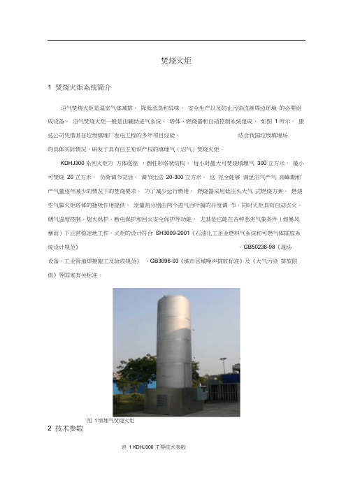
沼气焚烧火炬一般是由辅助进气系统、塔体、燃烧器和自动控制系统组成,如图 1 所示。
康达公司凭借其在垃圾填埋厂发电工程的多年项目经验,结合我国垃圾填埋场的具体实际情况,研发了具有自主知识产权的填埋气(沼气)焚烧火炬。
KDHJ300系列火炬为方体底座,圆柱形塔状结构。
每小时最大可焚烧填埋气300 立方米,最小可焚烧20 立方米。
负荷调节灵活,调节比达20-300 立方米。
这完全能够满足沼气产气高峰期和产气量逐年减少的情况下的焚烧要求。
为了减少运行费用,燃烧器采用低压头大气式燃烧方案,燃烧空气靠火炬塔体的抽吸作用提供,流量则分别由两个进气百叶窗的开度调节。
同时火炬具有自动点火、烟气温度控制、熄火保护、断电保护和回火安全保护等功能,尤其是它能在各种恶劣气象条件(如暴风暴雨)下正常稳定地工作。
火炬的设计符合SH3009-2001《石油化工企业燃料气系统和可燃气体排放系统设计规范》、GB50236-98《现场设备、工业管道焊接施工及验收规范》、GB3096-93《城市区域噪声排放标准》及《大气污染排放限值》等国家有关标准。
图 1 填埋气焚烧火炬2 技术参数表 1 KDHJ300 主要技术参数3 系统特点及功能5.3.1 系统特点①、专门针对填埋气、沼气、瓦斯等低热值气体设计。
②、燃烧效率高,达到95%以上。
③、负荷调节灵活,调节比达20-300 立方米。
④、燃烧安全,火焰稳定。
⑤、强大的控制功能,便利的操作系统。
⑥、能适应各种气象条件。
⑦、较长的使用寿命。
⑧、烟气排放少。
⑨、噪音低。
⑩、可做CDM项目。
5.3.2 系统功能康达公司的沼气焚烧火炬系统是一个独立、完整的系统,主要包括以下功能:1) 沼气在进入抽气风机之前,具有相应的除湿、过滤等工艺,以满足设备的长期、稳定运行的需要。
我们公司设计的系统工艺流程为:沼气→除湿过滤→抽气风机→监测仪表→ 阻火器→火炬。
火炬操作手册(初版)
徐州矿务集团有限公司150万吨/年甲醇项目首期60万吨/年甲醇工程火炬系统操作维护手册(初版)设计:校对:审核:中国船舶重工集团公司第七一一研究所二○一二年六月目录1、概述 (1)1.1火炬气体条件 (1)1.2公用工程条件 (4)1.3气象条件 (5)2、开车前的准备 (7)2.1管线检查 (7)2.2管线吹扫 (7)2.3公用系统检查 (7)2.4仪表检查 (7)2.5电气检查 (8)3、公用工程管线启用 (8)3.1氮气引进 (8)3.2仪表空气引进 (8)3.3燃料气引进 (8)3.4蒸汽引进 (8)3.5新鲜水引进 (9)4、地面内传焰点火器 (9)4.1地面内传焰火器的组成 (9)4.2点火前调试 (9)4.3点火调试 (10)5、高空点火装置 (10)5.1高空点火装置的组成 (10)5.1.1高能发生器 (11)5.1.2电缆 (11)5.1.3点火电极 (11)5.1.4高空点火枪 (11)5.2点火准备工作 (11)5.2.1点火器柜通电前检查 (11)5.2.2通电试验 (11)5.2.3通气试验 (12)5.3高空点火装置的点火 (12)5.3.1现场手动点火 (12)5.3.2 PLC面板手动点火方式 (12)5.3.3 PLC控制自动点火方式 (13)6、长明灯点火控制系统操作 (13)6.1现场PLC控制柜 (13)6.1.1 电源开关 (13)6.1.2 控制开关 (13)6.1.3 控制按钮 (13)6.1.4 指示灯 (14)6.1.5 显示界面 (14)6.2点火操作 (14)6.2.1 自动点火 (14)6.2.2 手动点火 (14)6.2.3 DCS遥控点火 (14)7、蒸汽消烟控制 (14)8、液位控制 (15)8.1分液罐、水封罐的液位控制 (15)8.2水封罐补水控制 (15)1、概述新建高架火炬用于处理买方年产60万吨/年甲醇项目正常、事故、紧急、非正常生产工况下的排放气。
火炬说明书

注意:本手册只适用于重庆万盛煤化有限责任公司煤制醋酸项目火炬系统调试和培训使用。
陕西金黎明石化工程有限公司 售后服务部 Tel: 029 3862 7004-806
Fax: 029 3861 2810
目录
企业简介 1 项目概述 3 工艺流程 4 系统配置 6 点火设施 10 系统调试 19
8
系统配置
水封罐设置进出气管、进水管、排水管、人孔及梯子、平台等,罐体设置就 地液位计和自控液位计(高、低报警)、温度计、压力表等。为防止冬季结冰, 水封罐外部采用岩棉材料保温,内部设置蒸汽盘管作为伴热措施。
水封罐设置液位就地指示和低液位报警、高液位溢流。补水设置自动补水方 式。
八、 节能长明灯
本项目共设置 6 支 JCM-Ⅰ节能型长明灯。长明灯采用文丘里原理,引射空 气预混型。
有火焰稳定装置,在马赫数 0.5 以下时,火焰都具有一定的稳定性。 在火炬燃烧器头口设置由耐高温合金(加涂高温陶瓷)构成的 S 型多孔聚 火块(钝体),多个聚合块又形成一个稳火圈,聚火块(圈)是多种稳火装置的 综合运用。其作用是在火炬头出口处建立一个高温燃气回流区作为点火源,从 而保证火焰的稳定,由于每个聚火块上有孔,可在块后形成回流区,回流来的 已燃热气与从小孔出来的混合气接触,靠分子扩散和湍流来输送点火能量,在 小孔处形成“袖火”。 另外,火炬燃烧器头口设置的 4 支长明灯既作为初期的点火源,也能在正 常运行时为火炬气提供连续的稳定热源,保证低热值的排放气可靠点燃。 延寿措施: 本火炬燃烧器上部易损部件进行了高温陶瓷处理(聚火块、长明灯头、爆 燃管等),使火焰与母材隔离,火炬头具有耐高温、防腐蚀的优点。 火炬燃烧器头部稳火块采用含 Ni 耐热合金 310SS 材料制造,提高耐热耐蚀 耐氧化性能,在 1000℃时长期使用。 z 火炬燃烧器头部设有安装环和稳火块,其材料为 310SS。 z 火炬燃烧器材料采用 310SS/304 不锈钢;满足系统要求寿命大于 15 年。 z 火炬燃烧器外表面喷涂有机硅耐热漆。
全厂火炬DCS技术规格书

3 系统功能要求……………………………………………………………………………………..8 3.1 控制功能……………………………………………………………………………………….8 3.2 画面功能………………………………………………………………………………………9 3.3 报表功能………………………………………………………………………………………10 3.4 历史数据存储功能……………………………………………………………………………11 3.5 本单元系统功能要求 …………… …………………………………………………………11
2 DCS 规模数据
2.1 输入/输出信号类型 DCS 的过程控制器应能直接接收或处理以下各种类型的输入和输出信号:
江苏中圣石化 工程有限公司
DCS 技术规格书
图 号 0813/440-100-50-
1) 模拟量输入 a 热电偶(Types J、K、E、R、S、T、B) b 热电阻(RTD) c 4~20mA DC 二线制电流信号 d 4~20mA DC 有源电流信号 e DC 电压信号 f 脉冲频率信号
3)对其 DCS 系统提出优化配置方案及系统工程,包括控制室平面布置图,系统配置图、设备/组件清 单、设备的热负荷、电源消耗、电路保护、接地要求、连接电缆(线)规格等。
4)负责完成全部的系统组态及生成工作,内容包括控制回路、参数指示、越限报警、各种组显示、历 史数据、联锁逻辑、顺序控制、各种用户画面等。
火炬操作规程2011.9.15

火炬岗位操作规程目录1.范围 (1)2.规范性引用文件 (1)3.岗位职责 (1)3.1职责 (1)3.2职权 (1)4.工艺原理及流程简述 (1)4.1工艺排放系统 (1)4.2点火控制系统 (2)4.3燃料气系统 (3)4.4氮气系统 (3)4.5仪表空气系统 (3)4.6蒸汽系统 (4)4.7生产水管线 (4)4.8凝液回收系统 (4)4.9主要设备介绍 (4)5.岗位操作法 (8)5.1 系统开车 (8)5.2 正常运行 (11)5.3 系统停车 (11)5.4主要控制说明: (12)5.5 正常生产现场巡检内容 (14)6.附表和附图 (15)6.1 主要工艺参数 (15)6.2 主要设备参数 (16)6.3 工艺流程图 (17)前言本规程规定了其适用范围、编写依据、岗位职责、工艺流程简述以及详细的操作方法。
由甲醇车间组织编写,生产部审核,总工程师、生产经理审批。
由生产部统一印制发放,本规程的最终解释权归生产部。
1.范围陕西榆林凯越煤化有限责任公司60万吨/年甲醇车间火炬岗位2.规范性引用文件压力容器安全操作技术华陆工程科技有限责任公司提供火炬岗位操作手册和PID图纸金黎明提供《火炬点火使用手册》3.岗位职责3.1职责3.1.1严格执行操作法,及公司有关开停车通知。
3.1.2严格执行各项工艺指标,对不合格工艺指标及时调整至正常范围。
3.1.3对重要工艺指标的调整及变化情况及时向班长、车间汇报。
3.1.4对本岗位的所有设备的安全运行负责。
3.1.5协同机、电、仪进行正常的维护和保养。
3.1.6加强相关岗位之间及岗位内部人员之间的沟通与协助确保生产安全、稳定、优质、高效运行。
3.1.7认真执行巡回检查制度。
3.2职权3.2.1有权制止违反操作规程的行为,并及时上报。
3.2.2对所负责的设备仪表有权提出修理、更换和校核的要求。
3.2.3有权提出操作中所必需的工具及防护用品。
3.2.4对突然发生的事故,有权进行先控制处理,后汇报。
火炬设备、筒体、塔架吊装及组装方案
目录1. 工程概况 (4)1.160万吨/年甲醇装置火炬系统概况 (4)1.280万吨/年甲醇装置火炬系统概况 (4)1.3火炬系统平面布置情况 (4)1.4火炬系统设备参数 (4)1.5火炬塔架系统组装后立面图 (5)2.编制依据 (5)2.1火炬拼装方案编制依据 (5)2.2火炬吊装方案编制依据 (6)3.火炬筒的预制与组装 (7)3.1火炬筒规格、材质、制作方式 (7)3.2火炬筒制作施工程序 (7)3.3火炬筒的排版及坡口尺寸 (7)3.3.1 单节筒体下料尺寸及坡口要求 (7)3.3.2 火炬筒体分段拼装 (7)3.4火炬排气筒卷管制作 (8)3.4.1 火炬排气筒卷管制作施工程序 (8)3.4.2 筒节制作组对要求 (8)3.4.3 筒节制作焊接 (9)3.4.4 筒节制作安装无损检测要求 (10)3.5火炬排气筒的防腐要求 (10)3.5.1 火炬筒体喷砂除锈要求 (10)3.5.2 火炬筒体底漆涂刷要求 (10)3.5.3 火炬筒体面漆涂刷要求 (10)3.6火炬排气筒的预组装 (10)3.6.1 预组装的目的和时间 (10)3.6.3 组装施工方法 (10)4火炬塔架预组装 (10)4.1火炬塔架预组装的目的及检查内容 (11)4.2对火炬塔架拼装场地要求 (11)4.3火炬塔架按吊装分段与图纸分节对应情况 (11)4.4火炬塔架的预组装程序和方法 (11)4.5火炬塔架中的高强螺栓连接 (12)4.5.1 对高强度螺栓的要求: (13)4.5.2 高强螺栓连接 (13)4.5.3 安装高强螺栓 (14)4.6组装技术要求 (14)5.火炬塔架及火炬筒的吊装 (15)5.1吊装参数 (15)5.1.1 60吨/年、80吨/年甲醇装置火炬塔架吊装参数 (15)5.1.2 80万吨火炬筒及附属设备吊装参数 (15)5.1.3 60万吨火炬筒及附属设备吊装参数 (15)5.2吊装方法 (15)5.2.1 火炬塔架的吊装 (15)5.2.2 火炬筒体的吊装 (20)5.2.4 水封罐及分液罐吊装 (23)5.2.5 吊耳及平衡梁设置 (24)5.2.6 塔架防吊装变形的加固措施 (25)5.2.7 塔架吊装临时工作平台的搭拆 (26)5.2.8 塔架附属工艺管道及电仪保护管的吊装 (26)6吊装索具的配备 (27)6.1塔架吊装索具配备 (27)6.2火炬筒吊装索具配备 (27)6.4分液罐吊装索具配备 (27)6.5火炬头吊装索具配备 (27)7. 吊装顺序 (27)8. 大型吊车站位及进场路线平面布置 (28)8.160吨/年火炬吊装行走路线及路基处理 (28)8.280吨/年火炬吊装行走路线及路基处理 (28)8.3300吨吊车站位地面要求 (28)9. 火炬系统塔架及设备安装要求 (29)10. 吊装进度计划 (29)10.1进度计划编制说明 (29)10.2火炬系统安装进度控制表 (29)10.3火炬系统安装进度控制计划 (31)10.4火炬系统安装进度计划网络图 (31)11. 60万吨/80万吨火炬系统安装人力资源计划 (32)12. 主要施工机具计划 (33)13. 安全措施及安全保证体系 (34)13.1安全体系设立 (34)13.2工作安全分析 (34)13.3吊装安全技术措施 (35)1. 工程概况1.1 60万吨/年甲醇装置火炬系统概况新建80万吨/年甲醇项目主装置布置在60万吨/年甲醇装置火炬系统内,为给新建80万吨/年甲醇项目提供建设条件,需将60万吨/年甲醇项目火炬系统拆除,再新建一座火炬系统替代。
火炬操作说明07.04.03
河南龙宇煤化工有限公司50万吨甲醇项目火炬系统操作维护手册中船重工集团公司第七一一研究所二○○七年四月目录第1章概况 (3)1.1概述 (3)1.2设计基础资料 (3)第2章开车前的准备 (6)第3章公用管线启用程序 (8)3.1蒸汽引进 (8)3.2压缩空气引进 (8)3.3燃料气引进 (8)3.4氮气引进 (8)第4章DHG-B型地面内传焰点火器 (9)4.1DHG-B型地面内传焰点火系统流程示意 (9)4.2DHG-B型地面内传焰点火器的组成 (10)4.3调试和点火前的准备工作 (10)4.4地面内传焰点火器的调试 (10)4.5地面内传焰点火器的点火 (11)第5章DHS-B型高空点火装置 (12)5.1高空点火装置点火流程示意 (12)5.2DHS-B型高空点火装置的组成 (12)5.3点火准备工作 (13)5.4DHS-B型高空点火装置的点火 (14)第6章火炬设施的正常运转 (16)6.1概要 (16)6.2仪表监视 (16)6.3现场巡查 (16)6.4注意事项 (16)第1章概况1.1 概述河南龙宇煤化工有限公司新建一座火炬系统,作为其相关装置的安全配套设施。
该火炬系统能够及时、安全、可靠地处理各装置正常或事故放空时的放空气,并满足环保要求。
新建火炬采用一座正方形变截面钢管塔架支撑。
火炬系统设主火炬、酸性气火炬各一套,火炬高度90米。
主火炬系统设火炬头、分子封、火炬筒体、长明灯、水封罐,酸性气火炬设火炬头(内设动态密封装置、外设燃烧室)、酸性气分离罐、长明灯,两套火炬系统共用一座火炬塔架和一套地面内传焰点火器。
主火炬排放直径DN800,酸性气火炬排放直径DN150。
主火炬头为扩散燃烧型火炬头,设4支长明灯、4套高空电点火装置。
酸性气火炬头为带动态密封装置的低热值拌烧火炬头,设2支长明灯、1套高空电点火装置,长明灯保持常燃。
1.2 设计基础资料1.2.1火炬工艺设计条件:1.火炬最大处理量:280000Nm3/h;2.放空气参数:a)主火炬放空工艺参数粗合成气变换气净化气甲醇气温度(℃)175~330 40 40 40流率(Nm3/h)215599 214022 137825 280000 分子量23.10 22.65 11.36 9.95H2O(mol%) 14.0 0.3 0.01H2(mol%) 19.1 43.0 65.91 70.64CO(mol%) 55.3 18.7 29.05 9.68CO2(mol%) 2.2 36.6 3.02 2.23H2S (mol%) 0.1 0.1N2(mol%) 9.0 1.2 1.91 16.15Ar(mol%) 0.2 0.05 0.08 0.76 CH3OH(mol%) 0.02CH4(mol%) 0.08b)酸性气火炬放空工艺参数酸浆汽提硫回收尾气温度(℃)100 25 流率(Nm3/h)28.8/4500 0/1500 分子量28.00 40.00H2O(mol%) 38.6H2(mol%) 2.7 0.01CO(mol%) 10.5 0.03CO2(mol%) 32.7 71.49H2S (mol%) 4.5 27.90N2(mol%) 0.45N3H(mol%) 8.4CH3OH(mol%) 0.12 HCN(mol%) 2.41.2.2火炬系统设计条件:1. 最大受热点到火炬筒中心线的水平距离35~50m;2. 测定高度处的年平均最大风速18.3m/s;3.火炬气排放总管直径DN800。
火炬操作说明
兖矿联工发化工有限公司气化炉及及醋酸装置配套工程高架火炬系统操作说明(试用版)档案号:YKEF2004-CZSM中船重工七院七一一研究所二○○四年十二月目录1概况 (1)2开车前的准备 (3)3公用管线启用程序 (5)3.1氮气引进 (5)3.2蒸汽引进 (5)3.3仪表用压缩空气引进 (5)3.4燃料气引进 (5)4DHG-B型地面内传焰点火器 (6)4.1DHG-B型地面内传焰火器的组成 (6)4.1.1地面内传焰点火器上的各路管线 (6)4.1.2空气、燃料气混合器 (6)4.1.3点火控制盘 (6)4.2DHG-B型地面内传焰火器点火前的准备工作 (6)4.3地面内传焰点火器D1508的调试 (7)4.4点火用燃料气、仪表用压缩空气点火配比调试 (7)4.5使用地面内传焰点火器D1508手动点火 (7)5DHS-B型高空点火器 (9)5.1DHS-B型高空点火器系统 (9)5.1.1DHS-B型高空点火器系统的组成: (9)5.2DHS-B型高空点火器系统的调试 (10)5.2.1运行前的检查 (10)5.2.2投电试验 (10)5.2.3通气试验 (10)5.3高空点火装置的点火 (10)5.3.1手动点火方式 (10)5.3.2手动遥操点火方式 (10)5.3.3自动点火方式 (11)6蒸汽调节 (12)6.1蒸汽消烟系统 (12)6.2蒸汽用量调节 (12)6.3气化炉、汽提气火炬头的伴烧气调节 (12)7火炬系统的自动控制 (13)7.1火炬系统自动点火 (13)7.2凝液的自动排除 (13)7.2.1罐凝液的排除 (13)7.2.2水封罐凝液的排除 (13)7.3水封罐自动补水控制 (13)8火炬设施的正常运转 (15)8.1概要 (15)8.2仪表监视 (15)8.3现场巡查 (15)8.4注意事项 (15)附图:1工艺配管及仪表流程图(YKEF2003-00/01-00)2地面内传焰点火器(YKEF2003-20/02)1 概况兖矿联工发化工有限公司为气化炉和醋酸装置新建三套火炬配套安全设施,要求各装置正常放空或事故放空时能够及时、安全、可靠地在此火炬设施放空燃烧,并满足环保要求。
集气站工程火炬系统使用说明书
点火电极、点火棒及高温高压绝缘子安装在点火器底部(火炬口下2米处),避开了高温区;
采用高温耐蚀合金制造高空点火器及点火电极、采用进口石英特制高温高压绝缘子;
点火棒由特种高温陶瓷制造,具有工作温度高,温升快(3秒达到1500℃),无电蚀、不积碳、耐腐蚀、耐高温、在风雨雪中点火可靠等特点;
φ219×20000~22000(排放量20万方/天);
φ325/φ219×25000(排放量30万方/天)。
3.3 HDJ-104半自动点火控制柜1个
位于控制室,内设自动/手动点火按
钮、逻辑控制单元,可实现远程半自动
/手动点火功能。
规格:2100×800×600
3.4 XDK现场点火控制柜1个
位于火炬现场,内设半自动/手动点火按钮、防爆接线箱、高压发生器,可在火炬现场实现高低压点火切换、半自动、手动点火。
双路(GD2)高压强电弧和低压点火棒两种点火方式,电极放电能量大,点火棒工作温度高,能在3秒内把冰雪融化,防风雨。
适用多种点火气源(瓦斯气、天然气、液化气、煤气等),点火压力范围宽(0.2~0.8MPa)。
3.6 GL高压线路2套
点火电极以下17米,采用多股高温合金丝传输高压以防止下火雨及高温辐射烧坏高压线路。
采用引射技术,在火炬头筒体上部设置气体引射防风罩,使火炬头无烟燃烧。按文丘里原理采用负压式引风大气扩散技术,利用放空气体在火炬出口的高喷射速度,将防风罩下部周围的大量空气引射到防风罩内,进行中心供氧,同时放空气体通过新型带空间锥体花瓣形稳火环后产生湍流与引射到防风罩内的空气进行充分混合,使火炬头在任何条件下都能稳定、安全燃烧,在恶劣气候条件下都能产生稳定火焰,火炬头喷出的排放气缩短了火焰高度及托高火焰,降低火炬头头部温度,延长了火炬头使用寿命。防风罩可避免火焰直接燃烧于火炬筒体外负压区,降低火焰偏斜程度,使火焰稳定燃烧,以延长火炬头使用寿命,避免大风造成的火焰倒卷或熄灭。
地面火炬

郑州光威高科有限公司地面火炬系统技术方案目录一、总则 (2)1.1 概述 (2)二、应用规范和标准 (2)三、设计和操作的环境条件 (2)3.1 公用工程条件 (2)3.2 放空气及燃料气(吹扫气) (3)四、供货范围 (3)4.1 概述 (3)4.2 范围 (4)4.3 相关的图纸、技术文件。
(5)4.4 卖方负责的界面 (6)五、火炬系统概述 (6)5.1 放空火炬工艺过程原理 (6)5.2 火炬自动点火控制原理 (7)火炬 (8)六、系统各部分结构、特点说明 (8)6.1 放空气体水封罐 (8)6.2 控制阀 (9)6.3 防辐射隔热罩 (9)6.4 安全防护墙和基础(参见图纸:CFP-DWG-0104PR01-02) (9)6.5 燃烧器组 (9)6.6 点火控制器的结构特点 (10)6.7 点火器的结构特点 (10)七、主要设备技术参数 (10)7.1 地面火炬的技术参数 (10)7.2 点火控制系统的技术参数 (11)7.3 远传控制系统的技术参数 (11)7.4 长明灯的技术参数 (11)7.5 高能点火器的技术参数 (12)7.6 燃烧器组的技术参数 (12)7.7 防辐射隔热罩的技术参数 (12)7.8 水封罐的技术参数 (12)八、地面火炬的安全保证措施 (12)8.1 第一级安全保证措施: (12)8.2 第二级安全保证措施: (13)8.3 第三级安全保证措施: (13)九、检验、试验和证书 (13)9.1 检验机构 (13)9.2 检验项目和试验内容 (13)9.3 证书 (13)9.4 铭牌 (14)十、性能保证 (14)一、总则1.1概述本规格书适用于炼油厂工程火炬设备,本规格书阐述了对放空地面火炬的设计、制造、检验、供货及运输保护等的最低要求。
二、应用规范和标准地面火炬系统的设计、材料采购、制造、检验、试验、供货运输等应遵循下属标准、规范:《石油化工企业设计防火规范》(GB50160—92)(1999年修订版)《火炬系统设置》(HG/T20570.12—95)《电气设备安装工程施工及验收规范》(GB50258—96)《环境空气质量标准》(GB3095-1996)《大气污染物综合排放标准》(GB16297-1996)《工业企业厂界噪声控制设计规范》(GBT87-85)《工业企业厂界噪声标准》(GB12348-1997)《PYH-400火炬自动点火装置》(Q/PYH010-1998)《爆炸性气体环境用防爆电气设备-通用要求》(GB3836.1-2000)《爆炸性气体环境用防爆电气设备-隔爆型d》(GB3836.2-2000)《爆炸性气体环境用防爆电气设备-增安型e》(GB3836.3-2000)《机电产品包装通用技术条件》GB/T13384-92《运输包装收发货标志》GB6388-86三、设计和操作的环境条件3.1公用工程条件3.1.1 电气、仪表要求卖方完成火炬系统内所有电气设施(含照明、防雷及静电接地)的设计、设备采购、安装。
封闭火炬说明书

封闭火炬说明书封闭火炬是一种用于特殊场合的照明装置,它具有防水、防尘、耐高温等特点,适用于户外活动、探险、紧急救援等情况。
本说明书将详细介绍封闭火炬的特点、使用方法以及注意事项。
一、特点1.防水防尘:封闭火炬采用特殊的材料和工艺制作而成,具有出色的防水和防尘性能,可在恶劣的环境下正常工作。
2.耐高温:封闭火炬内部采用高温耐热材料,即使在高温环境下也能正常发光,不会因温度过高而受损。
3.长寿命:封闭火炬采用节能高效的LED灯珠,寿命长达数万小时,无需频繁更换电池或灯珠。
4.便携轻巧:封闭火炬体积小巧,重量轻,便于携带,适合户外活动和紧急救援使用。
二、使用方法1.开关操作:封闭火炬的开关位于灯头或灯尾,根据具体型号可能有不同的设计。
使用前请先确认开关位置。
2.亮度调节:部分封闭火炬具备亮度调节功能,可以根据需要选择不同亮度档位,节约电池能量。
3.电池更换:当封闭火炬亮度明显减弱时,请及时更换电池,以确保正常照明效果。
4.充电方式:部分封闭火炬支持充电功能,可以通过连接电源或充电器进行充电,具体操作请参照产品说明书。
三、注意事项1.避免长时间连续使用:封闭火炬虽然具有高效的散热设计,但长时间连续使用仍有可能导致过热,建议适当休息。
2.避免触摸灯珠:使用过程中,请勿直接触摸灯珠,因为高温会导致烫伤。
3.儿童禁用:封闭火炬不是玩具,请放置在儿童无法触及的地方,以免发生意外。
4.防水性能:封闭火炬具有一定的防水性能,但并非完全防水,请避免长时间浸泡在水中。
5.存储方式:长期不使用时,请将电池取出,以免电池漏电导致损坏。
6.避免高空抛掷:请勿将封闭火炬抛掷至高空,以免造成伤害或损坏。
7.避免分解修理:请勿擅自拆卸封闭火炬,以免损坏产品或造成伤害。
封闭火炬是一款实用的照明设备,它的特点、使用方法和注意事项都需要用户仔细了解和遵守。
在户外活动、探险或紧急救援中,封闭火炬能够为我们提供可靠的照明支持,确保我们的安全和顺利完成任务。
L.B. WHITE 工业燃气火炬说明书

WORLD PROVIDER - INNOVATIVE HEATING SOLUTIONS411 Mason Street, Onalaska, WI, U.S.A 54650 • 800-345-7200 • 608-783-5691 • 608-783-6115 (fax) • SAFETY REGULATIONS FORL.B. WHITE COMPANY’S UTILITY TORCHESREAD AND SAVE FOR FUTURE REFERENCEDANGER: CARELESS USE OF LP-GAS AND RELATED EQUIPMENT CAN RESULT IN DEATH OR SERIOUS BODILY INJURY FROM ASPHYXIATION, FIRE AND/OR EXPLOSION. READ AND FOLLOW ALL OF THE ENCLOSED SAFETY INSTRUCTIONS AND OWNER’S MANUAL FOR THE SAFE USE OF L.B. WHITE TORCHES.Follow all requirements of local, state and national LP-gas safety codes. Your LP-gas dealer, your local fire department and governmental agencies can help you determine these requirements. In the absence of local codes, comply with the standards for the Storage and Handling of Liquefied Petroleum Gases, ANSI/NFPA 58-1979. If you have any questions whatsoever with respect to the requirements for LP-gas safety codes, please contact these agencies of the L.B. White Company at 608-783-5691.WARNINGS AND SAFETY INSTRUCTIONSI. DO NOT USE IN UNVENTILATED AREAS.A. U se of torches in unventilated, tightly enclosed areas or living quarters may cause death or serious bodily injury due to asphyxiation. Adequate ventilation and air is essential to safe operation.B. I f the flame in your torch becomes extinguished, shut off the gas immediately and wait a minimum of five minutes or until you are certain the gas has cleared away before relighting. Torches equipped with our safety control valve and thermocouple assembly are designed to automatically shut off the gas supply if the flame is extinguished. Models 124, 162, 163, 164 and 165, equipped with safety control valve and thermocouple assembly, are the only models appropriate for use in an enclosure, such as a kiln. If your model is not equipped with these devices, DO NOT USE THE TORCH IN ENCLOSURES. Even with safety controls, 100% supervision of the torch, when in operation, is required.II. D O NOT OPERATE ABOVE PRESCRIBED OPERATING PRESSURE. EXCESS PRESSURE MAY CAUSE BLOWOUT AND EXPLOSION AND RESULT IN DEATH OR SERIOUS BODILY INJURY. A. D O NOT direct flame toward the gas cylinder as heat causes increased pressure and the safety valves may open releasing gas into the air, which can explode if ignited by the torch flame. Keep torches six (6) feet away from all fuel containers. Keep temperature of all gas cylinders below 100 F. and if possible, install cylinders outside of enclosed areas.B. Use regulators and the hoses supplied with the torches and connect a regulator to the LP tank so that gas pressure in the hose is regulated at all times.C. U se of incorrect hose, regulator, POL, or excess flow valve may lead to gas leaks and explosion or asphyxiation. If the torch is purchased without a hose, POL, excess flow valve, or regulator or any of these items are lost or damaged, contact L.B. White to obtain information on the correct parts to use with each torch.III. CHECK FOR GAS LEAKS Incorrect assembly of torch can result in fire, explosion, death or serious bodily injury from asphyxiation due to gas leaks.A. F ollow assembly and operating instructions in owner’s manual, supplied with each torch, before using torch. If an owner’s manual is lost or not available, contact L.B. White to obtain a copy of it.B. I f you suspect a leak, or smell gas odor, EXTINGUISH ALL FLAMES AND SPARKS IMMEDIATELY, CALL LP-GAS DEALER AND FIRE DEPARTMENT.C. LP-gas is heavier than air and settles in low areas. DO NOT INSTALL LP-GAS burning equipment in an area where gas may settle.IV. INSPECT TORCH REGULARLY A. I nspect torch at time of installation for gas leaks and at least once a month and whenever accidental damage occurs. Test procedures are included in the owner’s manual included with each torch.B. I f the gas burning equipment is not working properly, remove from service immediately. Have equipment repaired and tested by an authorized person before placing it back in service.C. G as pipe joint compound that is resistant to liquefied petroleum gases should be used on all connections. Call L.B. White if you need assistance in identifying an appropriate compound.D. U se only L.B. White Company replacement parts on our torches: (a) T orch models with safety control valves and thermocouple assemblies use part number 02285, safety control valve. (b) Torch models with pilot safety control valves, thermocouple, and pilot light assemblies use part number 01233, pilot safety control valve.F #2845.0919Reprints are available upon request.。
语言生产公司的36S-20M-U煤气火炬说明书
Lang Manufacturing Company 6500 Merrill Creek ParkwayEverett, WA 98203Installation, Operation, Maintenance, & TroubleshootingModel: 36S-20M-U,RangeTHE INFORMATION IN THIS MANUAL IS CRUCIAL AND MUST BE RETAINED FOR FUTURE REFERENCE. READ, UNDERSTAND AND FOLLOW THE INSTRUCTIONS AND WARNINGS CONTAINED IN THIS MANUAL.CAUTION POTENTIALLY HAZARDOUS SITUATION WHICH, IFNOT AVOIDED, MAY RESULT IN MINOR ORMODERATE INJURY.NOTICE Helpful operation and installation instructions andtips are present.Model #: Purchased From:Serial #: Location:Date Purchased: Date Installed:Purchase Order #: For Service, Call:TABLE OF CONTENTSCHAPTER PAGE1. TABLE OF CONTENTS (3)2. LIST OF ILLUSTRATIONS (4)3. READ FIRST (5)4. SPECIFICATION SHEET (7)5. EQUIPMENT DESCRIPTION (8)6. UNPACKING (9)7. INSTALLATION (10)8. INITIAL START-UP (11)9. OPERATION (12)10. MAINTENANCE & CLEANING (13)11. PARTS LIST (17)12. RECOMMENDED SPARE PARTS LIST (18)13. WIRING DIAGRAM (19)14. WARRANTY (21)LIST OF ILLUSTRATIONSILLUSTRATION PAGE1. SPECIFICATION SHEET (7)2. RANGE TOP CONFIGURATION (8)3. LEG LAYOUT (9)4. ASSEMBLY (10)5. WIRING DIAGRAM (19)CAUTION EACH UNIT IS EXTREMELY HEAVY. FOR SAFE HANDLING, INSTALLER SHOULD OBTAIN HELP AS NEEDED, OR EMPLOY APPROPRIATE MATERIALS HANDLING EQUIPMENT (SUCH AS A FORKLIFT, DOLLY, ORPALLET JACK) TO REMOVE THE UNIT FROM THE SKID AND MOVE IT TOTHE PLACE OF INSTALLATION.CAUTION SHIPPING STRAPS ARE UNDER TENSION AND CAN SNAP BACK WHENCUT.NOTICE The Range data is located on the serial tag, which is riveted to the front of theunit in the lower right hand corner. The range voltage, wattage, serial number,wire size, and clearance specifications are on the data plate. This informationshould be carefully read and understood before proceeding with theinstallation.NOTICE The installation of any components such as a vent hood, grease extractors,fire extinguisher systems, must conform to their applicable National, Stateand locally recognized installation standards.CAUTION MAKE SURE THE SIX POWER LEADS THAT SUPPLY ELECTRICITY TO THECOOK TOP ARE NOT CRIMPED BETWEEN THE OVEN AND RANGE TOP.CAUTION BE SURE THE POWER SUPPLY VOLTAGE MATCHES THE VOLTAGESPECIFIED ON THE NAMEPLATE LOCATED ON THE FRONT OF THE RANGE.NOTICE During the first few hours of operation you may notice a small amount ofsmoke coming off the range, or out of the oven, and a faint odor from thesmoke. This is normal for a new range and will disappear after the first fewhours of use.CAUTION ALWAYS KEEP THE AREA NEAR THE APPLIANCE FREE FROMCOMBUSTIBLE MATERIALS.CAUTION KEEP FLOOR IN FRONT OF EQUIPMENT CLEAN AND DRY. IF SPILLSOCCUR, CLEAN IMMEDIATELY, TO AVOID THE DANGER OF SLIPS ORFALLS.CAUTION MOST CLEANERS ARE HARMFUL TO THE SKIN, EYES, MUCOUS MEMBRANES AND CLOTHING. PRECAUTIONS SHOULD BE TAKEN TO WEAR RUBBER GLOVES, GOGGLES OR FACE SHIELD AND PROTECTIVECLOTHING. CAREFULLY READ THE WARNING AND FOLLOW THEDIRECTIONS ON THE LABEL OF THE CLEANER TO BE USED.NOTICE Service on this, or any other, LANG appliance must be performed by qualifiedpersonnel only. Consult your authorized service station directory or call thefactory at 1-800-224-LANG (5264), or For theservice station nearest you.CAUTION USE OF ANY REPLACEMENT PARTS OTHER THAN THOSE SUPPLIED BYLANG OR THEIR AUTHORIZED DISTRIBUTORS CAN CAUSE BODILY INJURYTO THE OPERATOR AND DAMAGE TO THE EQUIPMENT AND WILL VOID ALLWARRANTIES.EQUIPMENT DESCRIPTIONELECTRIC RANGE EXTERIORThe Range dimensions are 30” (76.2cm) High (with out legs), 38” (96.5cm) Deep, and 36”(91.5cm) Wide.The Sides, Bottom, and Rear wall are constructed stainless steel.The Range surface comes with six 9” in diameter French Plates.ITEMS1 ea. RF21-HM-U (Range Top)1 ea. LA36SM-U (Bake Oven)4 ea. Bolt down legs2 ea. Operation Manuals1 ea. Marine Handle4 ea. ¼-20x½” HXD bolt S/S.4 ea. Lock Washer, S/SRANGE TOP CONTROLSThe 36S-20M-U Series Range comes with six French Plates that have a temperature range of200°F-750°F. Each French plate is controlled by one 6-heat switch. In addition the rangecomes with a standard bake oven that is controlled by two 3-heat switches that control the topand bottom element and one thermostat, with a range of 150°F-450°F that controls the overalltemperature or the oven. Below is a layout of the top configuration.36S-20M-URANGE TOP CONFIGURATIONUNPACKINGCAUTION EACH UNIT WEIGHS 600 LBS (THE TOP WEIGHS 410 LBS). FOR SAFEHANDLING, INSTALLER SHOULD OBTAIN HELP AS NEEDED, OREMPLOY APPROPRIATE MATERIALS HANDLING EQUIPMENT (SUCH ASA FORKLIFT, DOLLY, OR PALLET JACK) TO REMOVE THE UNIT FROMTHE SKID AND MOVE IT TO THE PLACE OF INSTALLATION.CAUTION SHIPPING STRAPS ARE UNDER TENSION AND CAN SNAP BACK WHEN CUT. RECEIVING THE UNITUpon receipt, check for freight damage, both visible and concealed. Visible damageshould be noted on the freight bill at the time of delivery and signed by the carrier'sagent. Concealed loss or damage means loss or damage, which does not becomeapparent until the merchandise has been unpacked. If concealed loss or damage isdiscovered upon unpacking, make a written request for inspection by the carrier'sagent within 15 days of delivery. All packing material should be kept for inspection. Do not return damaged merchandise to Lang Manufacturing Company. File yourclaim with the carrier.LOCATIONPrior to un-crating, move the range as near its intended location as practical. Thecrating will help protect the unit from the physical damage normally associatedwith moving it through hallways and doorways. UN-CRATINGThe range will arrive in two packages, each inside a wood frame covered bycardboard box and strapped to a skid. Remove the cardboard cover, cut thestraps and remove the wood frame. The unit may now be removed from the skid .INSTALLING THE LEGSTo install the legs, place some cardboard on the floor and gently tip the ovenportion of the range onto its back. A ½-13 threaded weld nut is provided in each ofthe four corners of the oven. Thread each leg into the threaded weld nuts and liftoven back onto the legs (See leg layout below).INSTALLATIONNOTICE The Range data is located on the serial tag, which is riveted to the front of the unit in the lower right hand corner. The range voltage, wattage, serial number, wire size, and clearance specifications are on the data plate. This information should be carefully read and understood before proceeding with the installation.NOTICEThe installation of any components such as a vent hood, grease extractors, fire extinguisher systems, must conform to their applicable National, State and locally recognized installation standards. ELECTRICAL CONNECTIONA 1¼” knockout is provided on the bottom left hand side of the oven below the control panel for power connection.The electrical connection must be made in accordance with local codes or in the absence of local codes with National Electrical Code latest edition (in Canada use : CSA STD. C22.1).Place spacers, (ie. 2 x 4 wood block not supplied) at the front and rear of the oven top.Place the range top on the spacers that are located on top of the oven.The six wire leads to supply electricity to the cook top are bundled under the front bottom of the top. Route these wires through the bushing provided in the oven top.Align the four locating pins in the bottom corner of the top with the four holes in each corner of the oven top.Remove the spacers and lower the top onto the oven.CAUTION MAKE SURE THE SIX POWER LEADS THAT SUPPLY ELECTRICITY TO THECOOK TOP ARE NOT CRIMPED BETWEEN THE OVEN AND RANGE TOP.The range can now be connected to power. CAUTION BE SURE THE POWER SUPPLY VOLTAGE MATCHES THE VOLTAGESPECIFIED ON THE NAMEPLATE LOCATED ON THE FRONT OF THE RANGE.Use the wiring diagram provided in this manual for determining the connections of the cook top wires to the oven terminal block.INITIAL PREHEATINITIAL PREHEATPrior to putting any range or oven into full time operation at normal cookingtemperatures, it must be thoroughly dried out. Moisture absorption in the closedspaces, in the insulation, and even inside the heating elements can cause futuretrouble if not properly treated.French PlatesTo “dry out” the French plates, set the 6-heat switch to position three. Allow the unitto operate at least 15 minutes at this heat level. Set the 6-heat switch to position fourand allow another 15 minutes to elapse. Set the 6-heat to position six and allow theunit to maintain the temperature for a minimum of 4 hours. More time may berequired if the unit has to operate in a moist environment.If the unit is out of use for three or more days, a one-hour preheat schedule should beused, especially when exposed to high humidity and/or cool temperatures.OvensTo “dry out” the oven, set the thermostat to 350°F and turn both 3-heat switches tothe low position. Turn on the power switch and allow the oven to saturate until allvapor and condensation has been eliminated. For best operating results allow therange oven to thoroughly dry out. More time may be required if the unit has tooperate in a moist environment.If the unit is out of use for three or more days, a one-hour preheat schedule should beused, especially when exposed to high humidity and/or cool temperatures.OPERATIONNOTICEDuring the first few hours of operation you may notice a small amount of smoke coming off the range, or out of the oven, and a faint odor from the smoke. This is normal for a new range and will disappear after the first few hours of use.OVENThe range oven must be thoroughly, preheated before satisfactory baking can be done. The range oven will not bake uniformly if not sufficiently preheated.To compensate for temperature drop when loading the range oven, set the thermostat up 50 degrees over the desired temperature. Reset thermostat after the range is loaded.The range oven may, of course, be preheated with the 3 heat switches set at a lower position than "High", but the time required will be proportionally longer. After preheating, set the two 3 heat switches for proper ratio of "top" and "bottom" heat to suit the product to be baked or roasted. The 12" high "Roasting and Baking" range oven is equipped with a removable rack. For baking pies, bread, or for roasting operations, the rack may be placed directly on the metal deck and the pans placed on the rack. For baking cakes or pastries the rack should be located in the lower position provided by the rack supports at the sides of the range and the pans placed on the rack in this lower position.The following temperature, time, switch setting and rack positions are suggested as a guide in baking various classes of products:General Class of Product Average Range TemperatureTime (Min.) With Metal Switch Settings Top Bottom Rack PositionPies 375-425 35-60 Low Medium Rack on Deck Rolls 375-400 15-30 Low High Rack Support Cake 350-400 20-45 Low High Rack Support Pastries 325-375 8-20 Low High Rack Support Bread 425-450 25-45 Low Medium Rack on Deck Roast Beef 300-325 Low High or Medium Rack on DeckFrench PlateA six-heat switch controls one French plate. Temperature settings range from 1(low) to 6(high). Recommended: Light duty saucepans and small stockpots. Not Recommended: Heavy stockpots, or heavy urns, or kettles.Set the 6-heat dial to the desired setting and allow for a thirty-minute preheat time to reach maximum temperature.CAUTION ALWAYS KEEP THE AREA NEAR THE APPLIANCE FREE FROM COMBUSTIBLE MATERIALS.CAUTIONKEEP FLOOR IN FRONT OF EQUIPMENT CLEAN AND DRY. IF SPILLS OCCUR, CLEAN IMMEDIATELY, TO AVOID THE DANGER OF SLIPS OR FALLS.CAUTIONMOST CLEANERS ARE HARMFUL TO THE SKIN, EYES, MUCOUSMEMBRANES AND CLOTHING. PRECAUTIONS SHOULD BE TAKEN TO WEAR RUBBER GLOVES, GOGGLES OR FACE SHIELD ANDPROTECTIVE CLOTHING. CAREFULLY READ THE WARNING AND FOLLOW THE DIRECTIONS ON THE LABEL OF THE CLEANER TO BE USED.CLEANINGAlways start with a cold range.The stainless exterior can easily be cleaned using Lang Mfg. Prime Shine (72804-41) oven cleaner.Always follow the cleaner manufacturer's instructions when using any cleaner.Care should be taken to prevent caustic cleaning compounds from coming in contact with the aluminized inside of the oven.Discoloration or heat tint may be removed using Lang Mfg. Carbon Release (72804-32) oven cleaner.Always apply these cleaners when the oven is cold and rub in the direction of the metal's grainThe range should be thoroughly cleaned at least once a week in addition to the normal daily cleaning to insure against the accumulation of foreign material. Keep-drip pans under range top plates clean. Keep hot plate and French plate surfaces clean. Outside of range and top should be kept clean.Electric equipment is inherently clean and sanitary, but may become unsanitary if grease is allowed to accumulate on it. Take advantage of the clean, sanitary features of electric equipment, give it the regular attention that it deserves the same as any other highly perfected machinery, to insure best results and continued high operating efficiency.EMERGENCY LOCKOUTLocate power disconnect at source and remove power from range .LONG TERM STORAGESecure range from power.Apply a generous amount of Lang Mfg. Prime Shine (72804-41) to the stainless steel.Apply a generous amount of Lang Mfg. Shipping Preservative Grease (72804-08) to the French plate surface.NOTICE Service on this, or any other, LANG appliance must be performed byqualified personnel only. Consult your authorized service stationdirectory or call the factory at 1-800-224-LANG (5264), or For the service station nearest you.CAUTION USE OF ANY REPLACEMENT PARTS OTHER THAN THOSE SUPPLIED BYLANG OR THEIR AUTHORIZED DISTRIBUTORS CAN CAUSE BODILYINJURY TO THE OPERATOR AND DAMAGE TO THE EQUIPMENT ANDWILL VOID ALL WARRANTIES.TROUBLE SHOOTINGOVENO VEN W ILL N OT H EATPROBABLE CAUSE CORRECTIVE ACTIONOven circuit breaker not on Cycle breaker to the “ON” position.Incorrect wiring Confirm that oven is getting proper voltage.Confirm that range is phased correctly.Defective Thermostat Confirm that thermostat is getting correct voltage.Confirm that thermostat is operating properly.Defective 3-Heat Switch Confirm that 3-heat switch is getting correct voltage.Confirm that 3-heat switch is operating properly.Defective Element Confirm that element is getting correct voltageCheck element for normal operation. (3.75 amps on the outside elementand 2.5 amps on the inside element)O VEN G ETTING T OO H OT OR N OT H OT E NOUGHPROBABLE CAUSE CORRECTIVE ACTIONDefective Thermostat Confirm that thermostat is getting correct voltage.Confirm that thermostat is operating properly.Thermostat out of Calibration Confirm that oven is getting to correct temperatureCalibrate oven (See instructions below).RANGEFRENCH PLATEFRENCH PLATE WILL NOT HEATPROBABLE CAUSE CORRECTIVE ACTIONIncorrect wiring Confirm the French Plate is wired correctly.Confirm that range is phased correctly.Defective 6-Heat switch Confirm that switch is wired correctly.Confirm that switch is operating correctly.Defective French Plate Confirm that French Plate is getting correct voltage.Confirm that French Plate is operating correctly. (5.5 amps)CALIBRATIONCalibration CheckPlace thermometer or thermocouple in the center of oven cavity.Set thermostat to 350°F and the top 3-heat switch to the high position and the bottom to the low position.Allow the oven to preheat for at least half an hour.Note cycle on temperatures and cycle off temperatures for 3 cycles. (Red indicator light indicates when oven is calling for heat)After 3 cycles average the temperature, (Add all six temperatures and divide by 6) the temperature should be +/- 15°F.Calibration AdjustmentA 1/16” flat blade screwdriver with a 2” shaft is required to make adjustments on the thermostat. Maintain the oven temperature at 350°F.Without turning the thermostat, remove the knob.Locate the adjustment screw at the base of the shaft and insert the screwdriver.Grasp the shaft and turn the screw. Counter clockwise to increase and clockwise to decrease (1/8of a turn will move the temperature 5-7 °F in either direction).Reinstall the oven knob and recheck the oven temperature.REMOVAL INSTRUCTIONSOVENThermostat and 3-SwitchThese parts are located behind the control panel assembly on the right hand side of the oven. To access control panel, remove the vent knob and the seven screws around the outside of the control panel assembly. Slowly pull the control panel toward you until the component is accessible.ThermostatInside the oven, remove the retaining clips holding the thermostat capillary tube to the inside of the oven. Feed the bulb through the oven wall into the control panel area. Pull out control panel as previously outlined. Remove knob and two screws that hold the thermostat to the oven control panel. Remove the wires from the old thermostat and attach to the corresponding terminal of the new thermostat. Discard old thermostat. Reinstall the thermostat and capillary tube into oven and the control panel and restore power to the oven. Test for proper operation.3-SwitchPull out control panel as previously outlined. Remove the wires from the 3-heat switch being changed. Place those wires on the corresponding terminal 3-heat switch. Remove old 3-heat switch and mount new 3-heat switch with wires attached. Discard old 3-heat switch. Reinstall the control panel and restore power to the oven. Test for proper operation.ElementsRemove oven rack. Bend tab on element clip using a pair of pliers so that the element may be removed. Gently pull elements down and to the left away from the right hand side of oven. Noting wire locations, disconnect wires from element. Discard old element. Reverse removal instructions to install. For bottom element removal it will be necessary to remove the bottom deck before removing elements. Removing the two screws on either side of the deck does this.RANGE TOP6-Heat SwitchRemove two sheet metal screws holding control panel to range top and remove control panel. Remove the 6-heat switch knob and two screws holding the 6-heat switch to the control panel. Remove wires from the 6-heat switch terminals noting the wire locations. Discard old 6-heat switch. Reverse removal instructions. French PlateUsing two 9” braces, lift the French Plate frame assembly up and secure with the two 9” braces. Remove wires from the element terminals, noting the wire locations. Remove defective French Plate assembly from the range. To install reverse removal instructions.PARTS LISTNO. DESCRIPTION PART Element 36 Oven 480 Volt O/S 1800 Watts 11050-29Element 36 Oven 480 Volt I/S 1200 Watts 11050-30Element French Plate 480 Volt 2600 Watts 11120-14Switch Rotating 3 Heat 30304-06Switch Rotating 6 Heat + Off 30304-09Thermostat 550°F Oven 30402-07Terminal Block 3 Pole Large 30500-07Timer Mechanical Long Ring 30801-01Pilot Light 480 Volt 6” Lead Black Body 31601-02Circuit Breaker 480 Volt 3-Pole 31800-04Rack Oven CLS Only 50200-72Handle Channel Marine 50300-14Element Pan Assembly with Snout 50300-20Handle Assembly Marine 50300-38Grab Bar Assembly 36” Long 50300-44Pan Latch Assembly Marine 50300-63French Plate Frame Assembly 50300-82Element Clip Long 50301-09Element Clip Short 50301-10Element Bushing Metal 50301-11Rotary Latch 50307-50Tension Disc Oven Door 50800-07Ship Rail 35 3/8” 50900-04Ship Rail Hooked 11 3/8” 50901-01Ship Rail Hooked 32 1/4” 50901-04Spring Left Side 7 1/2” Long – Oven Door 51001-01Spring Right Side 7 1/2” Long – Oven Door 51001-02Ship Rail Socket Front 60102-981Ship Rail Socket Rear 60102-982Knob Manual Timer 70701-09Knob 3 Heat Switch 70701-10Knob Thermostat 550°F Oven 70701-15Knob Damper Black 70701-25Knob 6 Heat Switch 70701-41RECOMMENDED SPARE PARTS LISTNO.QTY DESCRIPTION PART1 Element 36 Oven 480 Volt O/S 1800 Watts 11050-291 Element 36 Oven 480 Volt I/S 1200 Watts 11050-302 Element French Plate 480 Volt 2600 Watts 11120-141 Switch Rotating 3 Heat 30304-061 Switch Rotating 6 Heat + Off 30304-091 Thermostat 550°F Oven 30402-071 Timer Mechanical Long Ring 30801-011 Pilot Light 480 Volt 6” Lead Black Body 31601-021 Circuit Breaker 480 Volt 3-Pole 31800-041 Tension Disc Oven Door 50800-071 Spring Left Side 7 1/2” Long – Oven Door 51001-011 Spring Right Side 7 1/2” Long – Oven Door 51001-021 Knob Manual Timer 70701-091 Knob 3 Heat Switch 70701-101 Knob Damper Black 70701-251 Knob 6 Heat Switch 70701-41。
沼气火炬技术协议
技术协议甲方:十堰众工燃烧设备制造有限责任公司乙方:长春大成生物科技开发有限公司1.定购数量:沼气火炬一台。
2.火炬组成部分1)燃烧头直径max327mm,(不锈钢制造)2)倒流板(不锈钢制造)3)鼓风机:4-72-11No4A 带消音器。
4)电磁阀组:2W-40 不锈钢5)电动蝶阀:DN65 不锈钢6)电控箱(户外防雨雪型、元器件德力西) 400*5007)火炬塔体(A3炭钢)8)点火变压器 2*5000v9)压力检测器0-150mba3.火炬技术参数1)火炬型号:SYHJ-1202)燃烧方式:开放式3)燃料:沼气4)最大耗气量:80-160立方米/小时5)火炬供气压力不低于:2000pa(3000-8000之间最好)6)鼓风机电机功率:0.55KW7)供气管道:DN768)燃烧方式:二段式燃烧9)电磁阀组:DN40,(2W-40 1个)、(2W-50 1个)10)燃气调节阀:DN65 1套11)供风管道:DN220 1个12)点火变压器:XT-10 1个13)压力检测器:0-50mba 1个 50-150 mba 2个14)火炬高度:8米4.甲方负责安装.5.甲方严格按照技术协议要求供货,不得偷工减料,否则乙方有权退货,并且所有损失由甲方承担。
6.甲方严格地履行合同条款,按期将产品交付到乙方手中,由于甲方推迟交货所造成的损失,由甲方承担。
7.如设备出现质量问题。
甲方应在48小时内无偿派人到现场解决问题. 十堰众工燃烧设备制造有限责任公司长春大成生物科技开发有限公司签字:签字:年月日年月日。
火炬技术规格书
项目 气温 年平均温度
极端最高气温 极端最低气温 最热月平均温度 最热月平均最高温度 最冷月平均温度 最冷月平均最低温度
数值
项
目
风速
11.3℃
常年主导风向(东北风)
46.2℃ -28.7℃ 28.9℃ 39.1℃ -10.1℃ -19.5℃
年平均风速 最大风速 最大月平均风速 极端最大风速 历年平均大风日数 历年最多大风日数
1.2.6 本技术规格书用来反映买方要求,即使卖方产品符合本规格书的所有 条款,也并不解除卖方对其提供的设备和附件应承担的全部责任,所提供的设备
吐哈石油勘探开发指挥部 350×104Nm3/d 乙烷回收工程
火炬系统 技术规格书
乙烷项目部 2006 年 8 月 第 5 页 共 25 页
和附件应具有正确的设计,满足特定的设计和使用条件,遵守相关法律法规。
2.3 工艺条件
放空气条件见下表:
吐哈石油勘探开发指挥部 350×104Nm3/d 乙烷回收工程
火炬系统 技术规格书
乙烷项目部 2006 年 8 月 第 7 页 共 25 页
常低温火炬泄放量及组成一览表
工况 泄放量, kg/h 火炬筒底部压力,Kpa(g) 火炬筒底部温度,℃ 设计压力,Kpa(g) 最大预计背压,Kpa(g) 密度,kg/m3 假定火炬头压降,Kpa(g)
低压燃料气操作参数
操作参数
燃料气进口
最大
压力 kPa(a)
正常
燃料气进口 温度℃
最大 最小 正常
常规 1150 1127 52 25 45
低压燃料气组成
组分 H2S N2 CO2 CH4 C2H6 C3H8 IC4 nC4 H2O
2.5 相关规范、标准
火炬操作规程
1.装置概述 (2)1.1火炬的功能 (2)1.2 火炬气及公用工程 (2)1。
2。
1火炬气设计参数 (2)1。
2。
2公用工程 (3)1。
3 工艺流程 (3)1.4火炬的组成及其功能 (5)1.4。
1 火炬头 (6)1。
4。
2火炬筒体 (6)1.4.3分子密封器 (6)1.4。
4水封罐 (6)1.4。
5分液罐 (7)1.4。
6火焰传输器 (7)1.4.7 节能型长明灯 (7)第2章公用工程启用程序 (7)2。
1 蒸汽引进 (7)2。
2 燃料气引进 (8)2。
3 氮气引进 (8)第3章装置点火 (8)3。
1火炬点火系统点火前准备 (8)第4章系统开车 (10)4.1手动操作 (10)4。
1.1 手动点火操作程序 (10)4。
1。
2地面爆燃点火装置的调试、使用方法 (10)4.2自动运行 (11)4.3远程操作 (11)第5章系统停车 (11)第6章装置联锁 (12)第7章常见故障及维修 (13)第8章火炬设施的正常运转 (14)8。
1 概要 (14)8。
2 仪表监视 (14)8。
3设备正常运行时点检内容 (14)8.4安全注意事项 (14)1。
装置概述1.1火炬的功能xx项目在正常、事故、紧急、非正常生产工况下都会产生易燃、有毒的气体,为满足环保和安全需要,需经火炬焚烧处理后排放。
火炬可保证各有关装置单元在事故、紧急、非正常生产工况下产生的易燃、有毒的放空气提能够及时、安全、可靠的放空燃烧,并满足热辐射、有害气体排放达标等环保要求,不仅避免了这些可燃性气体与空气混合对整个生产装置形成的安全威胁,还使这些气体中有有害成分通过燃烧进行无害化排放,是一种必备的安全环保设备。
1。
2 火炬气及公用工程1。
2。
1火炬气设计参数1. 热火炬放空气(1)工艺设计参数见表1—1。
表1—1(2)气体组分见表1—2。
2. 冷火炬放空气(1)工艺设计参数见表1—3。
气体组分1.2。
2公用工程1.3 工艺流程系统点火前的准备(手动):应从放空气源头用氮气对放空气管道和火炬系统进行彻底吹扫.打开热火炬分子封的气封氮气阀和冷火炬的放空管氮气吹扫阀并在放空过程中始终保持常开, 确保火炬系统内部与外界空气隔离.(注意:密封隔离用氮气在火炬运行和停止放空期间都必须处于连续供应状态,证炬筒体内始终处于正压状态)。
蒲城火炬操作说明书
2.1 开车准备 .......................................................................................................................... 2 2.1.1. 开车前须具备的条件 ...........................................................................................................2 2.1.2. 开车前的检查 .......................................................................................................................2
第四部分 停车程序 .............................................................................................. 13
4.1 停车准备 ........................................................................................................................ 13 4.2 停车操作程序 ................................................................................................................. 13
140m火炬及炬气回收设备制作安装工程

140m火炬及炬气回收设备制作安装工程10140m火炬及炬气回收设备制作安装工程1 工程概况XX工程中新建的1座140m火炬,由中石化集团宁波工程公司和江苏中圣高科技产业公司联合设计,其主体设备包括主火炬头、主分子封、酸性气火炬头、酸性气分子封、主火炬筒体、酸性气火炬筒体、火炬塔架、分液罐等,结构为柔性塔架式火炬,截面为变截面三角形,火炬塔架高130m,安装标高+1m,根开28m,全平台共设2座,位置分别设在标高130、133.6m处,火炬筒体高度为135m,火炬头高(含分子封)为5m,主火炬主体总重量62吨,酸性火炬主体总重量24吨。
其具体技术参数见下表:2 编制依据2.1 工程合同2.2 火炬设施施工图纸 0810-00200-06236-01~112.3 《钢制焊接常压容器》 JB/T47352.4 《钢制化工容器制造技术要求》 HG205842.5 《钢制压力容器焊接规程》 JB/T47092.6 《钢制压力容器焊接工艺评定》 JB/T47082.7 《钢结构工程施工及验收规范》 GB502052.8 《石油化工安全技术规程》 SH35052.9 《工业管道工程施工及验收规范》 GB502352.10 《现场设备、工业管道焊接工程施工及验收规范》 GB502362.11 《石油化工吊装工作手册》上、下册3 施工工艺程序施工工艺程序见图14 施工方法、技术措施4.1 施工方法:本工程采用我公司成熟工艺—“塔筒互用倒正装技术”;此技术是结合我公司的专利技术—“贮罐液压提升倒装工艺”及其在设备制造领域的应用情况,经过重新设计和液压提升装置的改造,采用火炬筒体倒装的同时利用火炬筒体作主桅杆,在其上加设回转臂桅杆,进行火炬塔架安装的吊装工艺。
该工艺的实施解决了在无大型吊装机械、大型桅杆等机械设备的情况下或场地狭窄、丘陵地区火炬塔无法安装的困难。
4.2 工艺原理:主火炬筒体组装采用液压提升装置提升组装;在火炬筒体组装过程中,利用主火炬筒体作桅杆进行塔架的安装(正装);主火炬筒体的提升和塔架安装的稳定性由塔架本身予以保证,提升倒装和塔架正装交替进行,直至全部安装完毕。
- 1、下载文档前请自行甄别文档内容的完整性,平台不提供额外的编辑、内容补充、找答案等附加服务。
- 2、"仅部分预览"的文档,不可在线预览部分如存在完整性等问题,可反馈申请退款(可完整预览的文档不适用该条件!)。
- 3、如文档侵犯您的权益,请联系客服反馈,我们会尽快为您处理(人工客服工作时间:9:00-18:30)。
焚烧火炬
1 焚烧火炬系统简介
沼气焚烧火炬是温室气体减排、降低恶臭和异味、安全生产以及防止污染改善周边环境的必要组成设备。
沼气焚烧火炬一般是由辅助进气系统、塔体、燃烧器和自动控制系统组成,如图1所示。
康达公司凭借其在垃圾填埋厂发电工程的多年项目经验,结合我国垃圾填埋场的具体实际情况,研发了具有自主知识产权的填埋气(沼气)焚烧火炬。
KDHJ300系列火炬为方体底座,圆柱形塔状结构。
每小时最大可焚烧填埋气300立方米,最小可焚烧20立方米。
负荷调节灵活,调节比达20-300立方米。
这完全能够满足沼气产气高峰期和产气量逐年减少的情况下的焚烧要求。
为了减少运行费用,燃烧器采用低压头大气式燃烧方案,燃烧空气靠火炬塔体的抽吸作用提供,流量则分别由两个进气百叶窗的开度调节。
同时火炬具有自动点火、烟气温度控制、熄火保护、断电保护和回火安全保护等功能,尤其是它能在各种恶劣气象条件(如暴风暴雨)下正常稳定地工作。
火炬的设计符合SH3009-2001《石油化工企业燃料气系统和可燃气体排放系统设计规范》、GB50236-98《现场设备、工业管道焊接施工及验收规范》、GB3096-93《城市区域噪声排放标准》及《大气污染排放限值》等国家有关标准。
图1 填埋气焚烧火炬
2 技术参数
表1 KDHJ300主要技术参数
序号项目参数
1 沼气压力8-10kPa
2 沼气气额定流量300m3/h
3 负荷调节范围20-300 m3/h
4 火焰燃烧温度800℃-1000℃
5 烟气排放温度500-700℃
6 沼气进气管径DE200
7 工作用电≤100W
8 装机容量≤1.5kW
9 高度 6 m
10 外径 1.2 m
11 重量 1.25t
3 系统特点及功能
5.3.1 系统特点
①、专门针对填埋气、沼气、瓦斯等低热值气体设计。
②、燃烧效率高,达到95%以上。
③、负荷调节灵活,调节比达20-300立方米。
④、燃烧安全,火焰稳定。
⑤、强大的控制功能,便利的操作系统。
⑥、能适应各种气象条件。
⑦、较长的使用寿命。
⑧、烟气排放少。
⑨、噪音低。
⑩、可做CDM项目。
5.3.2系统功能
康达公司的沼气焚烧火炬系统是一个独立、完整的系统,主要包括以下功能:
1)沼气在进入抽气风机之前,具有相应的除湿、过滤等工艺,以满足设备的长期、稳定运
行的需要。
我们公司设计的系统工艺流程为:沼气→除湿过滤→抽气风机→监测仪表→阻火器→火炬。
2)沼气火炬能够在甲烷体积浓度为50%时,在20~300Nm3/h的流量范围稳定的燃烧。
3)沼气火炬能适应25~70%的甲烷气体浓度,在甲烷含量少于25%时能够立即关闭火炬,
确保火炬运行安全。
4)沼气在塔体停留时间大于0.8秒。
5)燃烧器和阻火器能够防止回火。
6)火炬上设有1个观察孔,观察孔的位置能看到主火焰。
7)火炬设有一个紫外自检式火焰扫描装置。
紫外扫描确保火焰处于最佳覆盖状态。
若紫外
扫描仪监测不到火焰,会向控制系统发出报警信号。
8)火炬塔用高温漆进行防锈保护,并且使用高铝纤维的绝缘材料进行保温,火炬塔表面的
最高温度不超过60℃。
9)内设自动吹扫系统,在每次启动之前,对燃烧器内部进行强制通风。
10)火炬设一套丙烷点火系统,点火电磁阀受PLC控制。
点火系统包括高压包、点火器、火
焰探测器等基本元件。
11)火炬年点火失败率不高于5%,而且点火失败时会发出报警并切断供气。
12)火炬入口的进气阀靠系统的启动信号自动开启。
13)控制系统具有自动抽气、安全吹扫、甲烷浓度监测、点火监测、灭火保护等功能。
14)控制系统具有数据存储、历史数据查询功能。
15)火炬控制系统具备手动、自动运行等功能。
16)火炬系统的燃尽率在95%以上。
17)系统界线外的噪音低于80分贝。
18)运行中不见明火。
4 控制系统功能
19)系统操作简单,安全可靠。
为了保证系统的可靠性,采用进口的燃烧自动控制系统。
同
时利用高压电能点火器点火,灵活可靠。
控制系统有如下功能:
20)自动抽气
21)安全吹扫
22)甲烷浓度安全监测
23)压力监测
24)点火监测
25)熄火保护
26)自动点火
27)自动报警
28)紧急停止,也可人工紧急关闭
29)远程控制
30)手动、自动模式选择
31)数据存储
32)历史数据查询
5 辅助进气系统功能
33)沼气在进入抽气风机之前,具有相应的除湿、过滤等工艺,以满足设备长期稳定的运行
需要。
康达公司专门针对KDHJ300系列沼气燃烧火炬设计的辅助进气系统,具有如下特点:
34)辅助进气系统的所有设备都集成在撬装底座上,是一套完整的撬装系统。
设备之充分考
虑了防雨、防风的要求。
35)由变频器控制风机,增强了系统的稳定性和灵活性。
36)采用防腐设计,确保设备的长期运行。
37)所有与气体接触的材料均采用SUS304材料。
38)所有的就地仪表均满足防腐、防爆的要求。
6 设备性能
1)焚烧火炬系统的设计遵循SH3009-2001及其他相关国家标准。
2)当火炬燃烧时,地面最大热辐射强度不大于1.5KW/㎡。
3)当火炬燃烧时,地面最大噪音强度小于80分贝。
4)燃烧完全,将易燃和有害物质尽可能完全地转变为无害物质,燃烧效率不小于99%,排放物满足国家相关环保要求。
5)设备保修期内如果由于我方质量原因出现的损坏,由我方负责免费全部维修。
7 KDHJ300焚烧火炬设备清单
KDHJ300火炬设备表
康达新能源设备股份有限公司
设备表
档案号 HJ001设备
项目号 HKHJ-001 沼气放空火炬
点火燃烧控制方案
共1页第1页
日期 2013年10月
阶段运行
序号名称规格型号数量备注
1 燃烧自动控制器RA890G1245(HOREYWELL)1台防爆型
2 高能电子点火器S720A200-GHA(HOREYWELL)1台防爆型
3 高压点火线/ 5米
4 引火燃烧器/ 1只1Cr18Ni9Ti
5 火炬燃烧排放头DN80/100 1套SS304
6 火焰监测仪C7035A(HOREYWELL)1只防爆型
7 引火电磁阀ZBSF-15 1只防爆型
8 控制柜/ 1台调试合格
9 动力柜/ 1台调试合格
10 触摸屏Eview步科MT5620T 1台调试合格
11 PLC控制器西门子1台调试合格
12 PLC控制器扩展西门子模拟量模块调试合格
13 吹扫风机/ 1台调试合格
14 穿线管Φ4’’、6’’25米Q235
15 管道阻火器KZHQ-B DN100 1台SS304
16 燃气液动气阀VE5100A/V4055A 1只慢开快关
17 主燃电磁阀ZBSF-125 1只SS304
18 阻燃保温棉100*10*5 1批险燃型
19 保温棉固定网罩/ 1批SS304
20 截止阀DN15 PN1.6MPa 1批SS304
21 连接法兰JB/T81-94 1套SS304
22 压力表Y-100 1.0Mpa 2只校验合格
23 流量计/ 1只校验合格
24 主放空截止阀DN80 PN1.0MPa 2只试漏合格
25 控制电缆KVVP/2×1.0 mm2/ 据实提供
26 除湿过滤器株洲三联 SS304,含滤芯1台调试合格
27 罗茨风机一备一用1台调试合格
28 变频器AB公司一备一用1台调试合格
29 甲烷浓度在线监测仪/ 1台调试合格
30 压力变送器/ 1个调试合格
31 热电偶/ 2个调试合格
32 热电阻PT100 2个调试合格
33 手动碟阀D371X-1.0 DN125 4个SS304
34 法兰PL100-1.0RF / SS304
35 火炬塔体/ 1个
36 撬装底座/ 1套
37 其他连接附件/ 1套
8 工程案例
海口市颜春岭垃圾场1000m3/h 一台成都垃圾填埋场300m3/h
重庆长生桥垃圾场1000m3/h。
