BPS_Platform_7.2产品安装指南
bps使用手册.
使用手册目标:掌握 BPS 软件的基本操作流程,以及基本 IP 模块的使用目录:一 . Matlab/simulink建模 (2)1. 在开始栏中打开 Xilinx System Generator ,启动进入 system generator (2)2. 运行‘ bps_new_model’命令,选择 mBEE4,点击 ok (2)3. 保存工作 (3)4. 选择系统配置 (3)5. 添加 IP GPIO Out (4)6. 配置 GPIO Out 参数 (5)7. 添加模块 (5)8. 配置 Counter 和 Slice 参数 (6)9. 添加 Simulink Display 和 Scope 模块 ..................................................................................6 10. 添加相关模块 ......................................................................................................................7 11. 配置相关参数 ......................................................................................................................7 12. 建立 Subsystem. (9)13. 系统进行 Simulink 仿真 ................................................................................................... 10二. Bps 编译综合 (10)1. 打开bps (10)2. 选择 Design rule check ,点击 Run BPS ,检查整个设计是否满足规则 (10)3. 选择 Complete build ,并选择 Fork processes ,点击 Run BPS ,编译工程 .................. 11三. 下载验证 .................................................................................................................................13将配置文件下载到 miniBEE4的 FPGA 中实现功能 ...........................................................131. 使用 FileZilla 将 bin 文件和 cdc 文件上传到远程服务器中 (13)2. 使用 vnc-viewer 进入 Linux 终端,运行 SelectMAP ,将 bin 文件配置到FPGA....... 14四.硬件调试:. (14)1. 使用 VNC 客户端,登陆到 miniBEE4,打开 Xilinx ChipScope Analyzer 软件 (14)2. 将 cdc 文件加入进来 (15)3. 运行查看信号 (15)软硬件协同教育部工程中心过程:一 .Matlab/simulink建模1. 在开始栏中打开 Xilinx System Generator ,启动 matlab R2012a 并进入 system generator 。
微热通信快速安装指南说明书
M I C R O T H E R M O T E C H N O L O G I E S™MT Alliance – DT-EEPR QuickSetup GuideDocument No. 72-MTA-1025-R0.5No part of this publication may be reproduced,stored in a retrieval system, or transmitted, in anyform or by any means, electronic, mechanical,photocopying, recording, or otherwise, withoutthe prior written permission of Micro ThermoTechnologies.© 1997-2015 by Micro Thermo Technologies.All rights reserved worldwide.Local Phone: (450) 668-3033 | Fax: (450)668-2695Toll Free Canada: 1-888-664-1406 | Toll Free USA: 1-888-920-6284/micro-thermoTABLE OF CONTENTS1. Introduction (1)2. Refrigeration Configuration (1)3. Hardware Installation (1)4. Control of EEPR Valves (2)5. Set Up of RefUnits (6)6. EEPR Control of RefUnits (8)7. Defrosts (10)7.1 Circuits Controlling more than One EEPR Valve (10)8. Valve Control, Set Point (11)9. Historical Data (11)10. Process Page (12)10.1 Details of the Process (13)11. Trendgraphs (13)12. Environmental Corrections (14)13. Valve Replacement and Other Repairs (15)13.1 What to do After a Repair (15)1.IntroductionIn this Quick Set Up Guide, you will find a step-by-step procedure to set up temperature control ofrefrigerated units using EEPR (Electric Evaporator Pressure Regulator) valves and the DT-EEPR6-valve Controller (Micro Thermo part number 950-636C).The DT-EEPR (Dual Temperature) controller issupported in Alliance v. 5.2 or later.2.Refrigeration ConfigurationSet up the rack, condenser, suction groups and cir-cuits, using the Refrigeration Configuration Tool(RefSysConfig.exe). Specify an Electronic EPR as theEEPR Control Actuator for the Refrigeration Cycle. Creat-ing the rack and entering a number for its first Circuitis the minimum required to obtain the View in Alli-ance.3.Hardware Installation1.On the controller, connect the earth ground (1 or 2), the EEPR valves (3) and the network (4).2.Power up the controller (24V AC) using the connector identified as AC1-AC2 (5).–The +5V green LED (6) lights up immediately.–The “Factory” red LED (7) and “SA” (Stand Alone) green LED (8) light up if the controller has never been used.–On outputs without valves, the LED (9) blinks very briefly (drive searching for a valve.)–On outputs with a valve, the LED blinks while the valve moves during its initialization, then remains ON. It takes about 4 minutes for 6 Sporlan valves to get initialized and positioned. The valves are positioned at half their total number of steps, if the board is in Factory condition. If the board was used previously, each valve returns to where it used to be during refrigeration. Warning : overloading transformers will result in overheating and may cause a fire. A DT-EEPR controller requires 2.1 amperes when driving Sporlan valves, and 3.4 amperes for Alco valves. A100VA, 24V transformer drives only two DT-EEPR boards with Sporlan valves, for example.4. Control of EEPR ValvesAfter this section is completed, you will be able to use the Plug-In to set EEPR valves to any desired value of %Open.1. Drop a node in Alliance (10), choosing the proposed version of Refrig Dual Temp EEPR (11).2.Click on the new node’s button (12) and, in the Details Page, give it a significant name, such as LT-EEPR1 (meaning the first Low-Temperature DT-EEPR node.) 3.Go to the Commands/Status Page and click on the Install button (13). Install the node by pressing the Service Button on the board itself, or by Manual Entry (14) of its node ID (sticker on the board.)– Loading the node software takes about 2 minutes. Each valve then gets reinitialized and positioned at its Stand Alone Position (50% of the number of steps, for a board that has Factory status.)10111413121617154.Drop a plug-in (15). Just to keep things simple, identify it by the same name as the node (16).Select the Dual Temp EEPR (17).Suggestion: The Rack’s Viewis usually a convenient loca-tion (18) to drop the plug-in.185.Open the plug-in, by clicking on its button.– “Stand-Alone Mode ON ” warnings (19) appear. In Stand-Alone mode, the node positions the valves according to the best of its knowledge, then waits for further instructions.6. In the Node Configuration box, specify the ValveSeries (20-21) (ex. Sporlan CDS).192019217.Open the Valve Config page (22).– Yellow “Detected” dots (23) indicate the outputs that presently have valves connected to them. 8. Specify the valve models (24)(ex. CDS-9).– Note : CDS-16 (angle) and CDS-17 (in-line) valves are in-terchangeable, as far as control is concerned.The Start Up feature may now beused on any valves that require im-mediate positioning :9. Click on the Start Up button(25). Enter the desired valve’s %Open (percentage of open-ing) (26) and click OK.10. At the bottom left corner of the Valve Config page, select the Rack in which the DT-EEPR isinstalled (27).11. Select the refrigerant (28).– Refrigerants are managed by the EEPR systems independently of RefSysConfig. Different names may be used for the same refrigerant, such as R507 in the EEPR and its alias, AZ50, in RefSysConfig.23242233262512. Click Apply.– The “Stand-Alone” warning disappears.– The “SA” (8) and the “Factory” (7) LEDs are now both OFF (the board being configured). – The valves get Initialized and positioned one by one, which takes about 4 minutes for 6 Sporlan valves.13. Open the Process page (29).– The valves are not yet assigned (30) to any RefUnit. – The valves are in StartUp mode (31).– Valves have reached their Start Up position, the default being 50%Open.– Actual values of %Open are shown (32), that may differ slightly from the requested values, such as 19,8% instead of a requested 20%. They are at the closest available step.– Valves can be repositioned at any time by changing the Start-Up (25) value in the Valve Config page and clicking Apply.– An Internal Schedule (33) for Off Time defrost is available immediately.Overrides (34) could be used to position valves, but defrosts are not supported in Override mode. The Start Up mode (with or without Off Time defrosts) enables you to start refrigeration even be-fore RefUnits and Circuits are configured, if the need arises.5. Set Up of RefUnits1. Complete the set up of the rack in RefSysConfig, if applicable. In order to use the EEPR valves for automatic temperature control, the refrigerated units (cases, walk-ins or open areas) must be represented by a software object called “RefUnit”, that is configured by a plug-in.2. Drop a RefUnit (35) plug-in for each refrigerated unit in the MainView.293031323436 3735A RefUnit can be used to represent a single case, or a row of identical, contiguous cases. In the above figure, for example, the installer uses the same RefUnit to represent the 3 cases (assuming that they are on the same EEPR valve). He could also drop an Auxiliary RefUnit (36) to represent the case on the left hand side, and a another one (37) for the case on the right hand side.3.Set up the RefUnits in Alliance, according to the RefUnit Quick Set Up Guide.Note : it is recommended to use RefUnits for all refrigerated units, including those that are not con-trolled by an EEPR valve.38For the EEPR valve to appear (38) in the Process page of the RefUnit, it must have been declared in the Control page of the RefUnit’s plug-in.In the DT-EEPR environment, RefUnits and valves are set up inde-pendently of one another, and in any order. When a RefUnit and its valve are both configured, temperature control and monitoring is achieved by one click of the mouse. This association is done in the DT-EEPR plug-in, as described below.6.EEPR Control of RefUnits1.Open the DT-EEPR plug-in at the Valve Config page.2.Select the Primary RefUnit (39) served by each EEPR valve.3.At the bottom of the Valve Config page, click in one of the two yel-low boxes (40) to confirm the default value of the suction pressureset point.The value suggested by the plug-in comes from the set point in the SPC. If it is not available, or if you wish to use a different value, simply enter the pressure or its equivalent saturated temperature.A DT-EEPR node supports two Suction Groups. If the RefUnits are not all on the same Suction Group, you will be asked to confirm (or provide) two suction pressure set points.–Any Dual Use or Clean switch defined in the RefUnits appears in the Available Features (41) panel. 394041There may be more than one control temperature sensor, associated with an EEPR valve. This usual-ly happens :• when a RefUnit includes more than one evaporator, each evaporator hav-ing its own temperature sensor. This is illustrated as Sys20 on Page 7, where one RefUnit includes three 5-door cases,• or when the EEPR valve controls Auxiliary RefUnits in addition to its Primary RefUnit, as illustrated above with Sys20a-b-c.In the figure on top of this page, Sys20b is the Primary RefUnit, Sys20a and Sys20c are auxiliary units. Each has its own temperature sensor that must con-tribute to the control.When you pick a Primary RefUnit that is linked to more than one control tem-perature sensor, the RefUnitDetails button (42) in the DT-EEPR Plug-In turns yellow, indicating that some input is required on your part.4. Click on the RefUnitDetails button (42).5. Select any availablecalculation block (43). 6. Set the operator (44)to Average, for low temperature applica-tions, and to Mini-mum for medium temperature applica-tions.Sys20a Sys20b Sys20c4243447. DefrostsDefrost parameters are accessed through the Valve Config Page, that has one button (45) for de-frosts controlled by a Circuit, and another button (46) for Internal Defrosts.In a typical supermarket, most defrosts are controlled by a Circuit of an MT-CKT node, and are done with the EEPR valve closed. In that case, you may not have to do anything, since the RefUnit already knows its Circuit.1. For valves with defrosts controlled by a Circuit node, open Circuit Defrost Details. Enter thedesired valve %Open for Pump Down, Active Defrost (47) and Drip.For Dual Temp cases using a CDS-9 EEPR valve, a 40%Open value is suggested for hot gas defrost through the valve. Opening the valve fully will take more time and not significantly increase the flow. 2. For valves with Internal Defrost, edit the schedule (48).Internal Defrosts are done off-time, by simply closing the EEPR valve. The schedule for Internal Defrosts is internal to the EEPR node and, in version 5.2 of Alliance, it is not yet integrated within the rack’s defrost schedule.7.1 Circuits Controlling more than One EEPR ValveWhen several EEPR valves are associated with a given Circuit for defrost, the DT-EEPR Plug-In automatically creates all the necessary bindings, so that defrost only starts after all the EEPR valves have been properly positioned. No intervention is required on the part of the user.45 474949488. Valve Control, Set Point– A warning (50) may appear in the Valve Control tab if the strategy seems inappropriate. This happens, for example, if the set point is within medium temperatures and the Strate-gy is set for frozen food.1. Click on the Details button (51) to open Strategy Detailsdialog box.The refrigeration Strategy determines how a RefUnit will be treated. Fresh meat, for example, will not load shed as readily as juice, and its temperature will be regulated more closely.2. Select the Strategy (52) that seems the most appropriate forthe type of merchandise.If you uncheck the Show All Strategies check box (53), you will see only those strategies which are compatible with the particular context of this RefUnit.3. Uncheck the Use from Primary RefUnit box (54) if youwish to set the temperature set point . Enter the desired value. For DualTemp RefUnits, two values are needed.If you leave this box (54) checked, the Optimal Value from the Alarm Set will be used as the set point. It will then be easier for the store personnel to modify it. It is assumed that the store per-sonnel have access to the RefUnits, but that they do not see the DT-EEPR plug-in. 4. Click Apply.– The DT-EEPR plug-in does all the bindings for you and sends the configuration to the node. – Temperature regulation begins.9. Historical DataYou may have been asked to select Historical Data. Even then, you need to do the following step. 1. Open the History page (55).2. Select all the data that you wish to log. Any unchecked network variable will not get logged, andyou will not be able to display it in Trendgraphs.50505154535255You may click on the Factory Default button to select automatically those network variables that are usually considered as the most important.10. Process Page1.Go to the Process tab and observe the following. – The names of the Primary RefUnits (56).– A thermometer indicating, for each valve, the Active Temperature Set Point (57), as well as the Instant (58) and Average (59) temperatures.– A banner (60) reveals any special valve status or activity (Defrost, Power Off, Override, etc). – Another banner (61) may show “Marginal” or the more severe “Conflict” warning. Conflict means that the valve is likely to run 100%Open all the time. Marginal means that the set point may be maintained, but not under extreme environmental conditions. In the case of Sys21 illus-trated above, a larger valve should have been used.– The actual %Open (62) of the valve is shown, with some visual indications (63) of its opening or closing (circles of decreasing or of increasing diameter.) A button is provided to force an Override (64).Note that the icon that represents a walk-in (room or open area) (65) is different from the icon rep-resenting a case.– Observe that the valves move as needed to maintain temperature, unless the circuit is undergo-ing a defrost. One move per minute is typical.After the valve has been in service for some time, a visual indication of the status of the control is displayed. A green circle means success. A red diamong (66) means that control could be improvedby tuning. A red square indicates that some intervention is probably needed.565758596061626364656610.1 Details of the Process1.Click on the buttons, at the bottom of the Process page, to access some additional information and trendgraphs. The bottom part of the Process page provides the following infor-mation :– the Active Set Point (67) (Set 1 or Set 2, for Dual Temp RefUnits only),– the EEPR control temperature, calculated from all the sensors involved, and referred to as “Instant Temperature” (68), – its running average (69), calculated over the last 15 minutes, – the accumulated Integral temperature error (70),– a button (71) that resets both the accumulated Integral and Long Term errors,– the location (72) of the Control Temperature Sensor in the Pri-mary RefUnit (normally Discharge Air for a case and Return Air for a room).The “Trend” button (73) opens a set of preselected trendgraphs for this RefUnit, and the “Less” button (74) hides the details.11. TrendgraphsThe underlined text contains hyperlinks to Trendgraph. If you click on Instant, for example, the Trendgraph for the (instant) EEPR Control Temperature opens. Prepackaged Trendgraphs are avail-able :1. Click on the “Trend” button to open the prepackaged Trendgraph for a RefUnit. –A new window opens, similar to the one below.7312. Environmental CorrectionsTo predict the valve %Open, the controller needs three environmental variables : the temperature and humidity around the case, and the temperature of the liquid refrigerant. These three environ-mental variables can affect the calculated flow of refrigerant by more than a factor of 2.The valve %Open is obtained from the calculated flow and pressure drop. PID corrections are then applied to obtain the final valve position. If the environmental corrections are not provided, the cal-culated value will be inaccurate, and the PID corrections will be used up to compensate. As a result, they won’t be available to compensate for other disturbances, and the site will become more vulner-able.With the DT-EEPR, setting up the Environmental Corrections takes only a minute. It is done as follows.1.The Space Temperature (75) is normally taken from the temperature sensor, inside the super-market, that is closest to the case or walk-in.2. For Space Humidity, any sensor inside the store, that provides Relative Humidity (76), can beused.3. Liquid Temperature is normally obtained from one of the nodes. nvoDlt (77) from the Con-denser node (Drop Leg Temperature) is a good candidate in some cases. If the rack is equipped with subcooling, the temperature of the liquid at the output of the subcooler is a better choice.– The indication of missing binding (78) disappears as its source is speci-fied.4. If, for some reason, you don’t have access to all three environmentalcorrections (liquid temperature not available, for example), provide those that you can. It will help.5. If an environmental correction becomes erratic (sensor malfunction, forexample) you can disable it by unchecking its box (79) in the Valve Ad-vanced Page. This can also be done to avoid getting the missing binding warning, if you were unable to provide the correction.7675777913. Valve Replacement andOther RepairsBecause the valve’s coils are induc-tive, unplugging a powered valve causes sparks that may disturb or, under extreme conditions, damage a controller.It is not necessary to power down the whole controller, in order to replace a valve. An individual drive can be powered off as follows. 1. Click on the Current Valuesbutton (80), to open the Cur-rent Values window. 2. Select the valve (81). 3. Click on Power Off.– The drive is powered Off. The valve will maintain its mechani-cal position until its drive is powered On again.– A Power On button replaces the Power Off button.– A Power Off banner appears in the Process page, reminding you that the drive is Off.– The Power Off condition also appears on top of the Valve Config page.13.1 What to do After a Repair1.Check that the valve is connected. If the drive is powered Off, you need to turn it back On, using the Power On (82) button in the Current Val-ues window.If the process has been running erratically for more than 30 minutes, it may be preferable to flush the accumulated errors. This is because the errors that were accumulated during the malfunction are not relevant to the present situ-ation. This is done as follows.2. Open the Process Page. If the More button appears, click on it to revealthe details. Then click on the Error Reset button (71)(83). – The Acc Errors value (84) goes to 0 after several seconds.8081828384Revisions HistoryCreation CB 08-Dec-060.1 Document0.1 Revision CC 31-Jan-07 0.2 More “Visual” version CB 09-Mar-07revision RL 20-Apr-070.3 Footer0.4 Logo and address changed RL 14-Dec-11。
EOS_Platform_7.6产品安装指南
普元信息技术股份有限公司EOS Platform 7.6产品安装指南文档修订记录目录1.概述 (1)1.1.开发版的安装内容 (1)1.2.企业版的安装内容 (2)2.配置要求 (3)2.1.硬件配置 (3)2.2.软件配置 (3)3.安装 (5)3.1.界面交互安装 (5)3.1.1.安装开发版 (5)3.1.2.安装企业版 (18)3.2.哑安装 (40)3.2.1.哑安装相关配置文件 (40)3.2.2.如何配置哑安装属性文件 (40)3.2.3.哑安装配置文件典型示例 (44)3.3.集群安装 (49)3.3.1.集群安装典型场景 (49)3.3.2.WebLogic集群安装 (49)3.3.3.WebSphere集群安装 (64)3.4.手工部署安装 (79)3.4.1.手工安装业务应用 (80)3.4.2. 部署资源配置文件示例 (89)4.卸载 (94)4.1.卸载开发版 (94)4.1.1.卸载注意 (94)4.1.2.卸载步骤 (94)4.1.3.验证卸载 (97)4.2.卸载企业版 (97)附录 (98)附录A 安装目录说明 (98)附录B FAQ (100)1.应用服务器为JBOSS时,启动时报异常。
(100)2.数据库为mysql时,前台出现乱码。
(100)3.Weblogic 新建domain未启动过的情况下安装EOS会报错,错误信息为空,不能安装。
(100)4.Oracle 9i环境下,启动EOS Server提示端口被占用。
(101)5.Oracle 9i环境下,安装EOS过程中,执行到“配置数据库”步骤时,数据库连接测试失败。
(101)6.初始化数据库时报错,表或视图不存在。
(102)7.WAS服务器环境下页面乱码 (102)8.安装包中的JDK切换,SQL Server数据库初始化报驱动类版本问题 (102)9.Weblogic服务器安装包安装过程中,出现数据库驱动类加载异常 (103)10.在Win10环境下安装产品时创建快捷方式失败 (103)11.在macOS sierra 10.12.1系统下Server启动非常慢 (103)12.在Websphere应用服务器下安装产品时报找不到数据库驱动的错误 (103)13.部分用户Mac开发版安装时会出现HeadlessException (104)附录C 安装包配置修改 (104)1.JBoss应用服务器 (104)2.WebLogic应用服务器 (105)3.WebSphere应用服务器 (105)附录D 界面安装应用服务器参数 (107)附录E 创建表空间 (109)附录F MySQL5.6的配置 (109)附录E 企业版安装在Tomcat8.5.5的配置 (110)1.概述EOS Platform产品包括开发版(Developer Edition)、企业版(Enterprise Edition)、标准版(Standard Edition)、基础版(Basic Edition)四种版本,支持界面交互安装、哑安装、集群安装和手工安装,具体如下表所示:本章主要介绍开发版、企业版的安装内容。
ARIS 7.2_win7安装手册
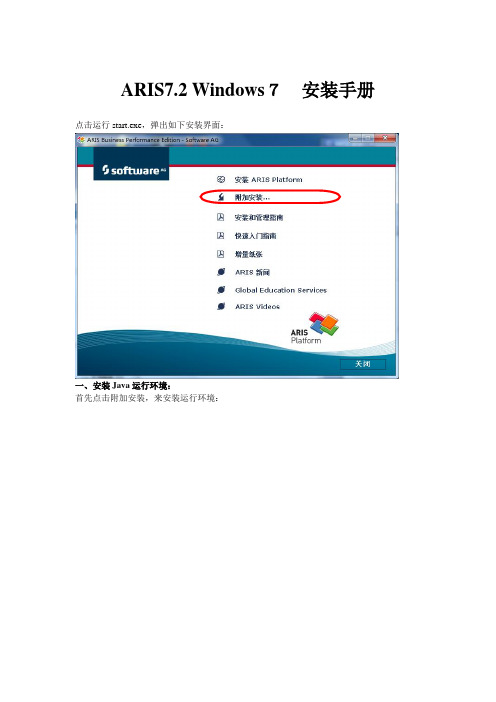
ARIS7.2 Windows7安装手册点击运行start.exe,弹出如下安装界面:一、安装Java运行环境:首先点击附加安装,来安装运行环境:点击:安装Java运行时环境:安装好Java运行环境。
二、安装ARIS Business Server:点击:安装ARIS Business Server点击:下一步点击:是选择对应的语言,点击:下一步选择:缺省安装选择对应的解密方式,点击:下一步选择对应的安装目录,点击:下一步选择安装Windows服务,点击:下一步然后静等安装完毕... 点击:完成三、安装ARIS Business Publisher服务器:点击:安装ARIS Business Server Publisher服务器进入欢迎界面,点击:下一步选择:我接受许可证协议中的条款,点击:下一步选择安装目录,点击下一步输入ARIS Business Publisher 许可密钥,点击:下一步选择ARIS Business Publisher 服务器,点击:下一步点击:下一步点击:安装 静等安装完成... ... 点击:完成安装完成后会自动在系统里面添加三个服务:ARIS Business Publisher Server7.2ARIS Business Server7.2ARIS Service Enabling1.0如果平时用的时候只是连接到远程服务器上可以停止此三个服务,或者将这三个服务改为手动启动。
以免影响开机速度四、安装ARIS Platform安装到此步的时候提示输入密钥,建议不要输入,等安装完成后,用模块的时候再输入密钥。
根据需要选择要安装的模块(建议全部选择),点击:下一步各模块功能介绍:ARIS Strategy Platform (ARIS战略平台)业务流程必须同公司目标协调一致。
使用ARIS 平台战略工具能够实现那个目标。
用户能够规划企业策略,优化和分析流程。
优化项目成本、人员规划和六西格玛方案 - 以及更多内容。
AIX 7.2快速入门指南说明书
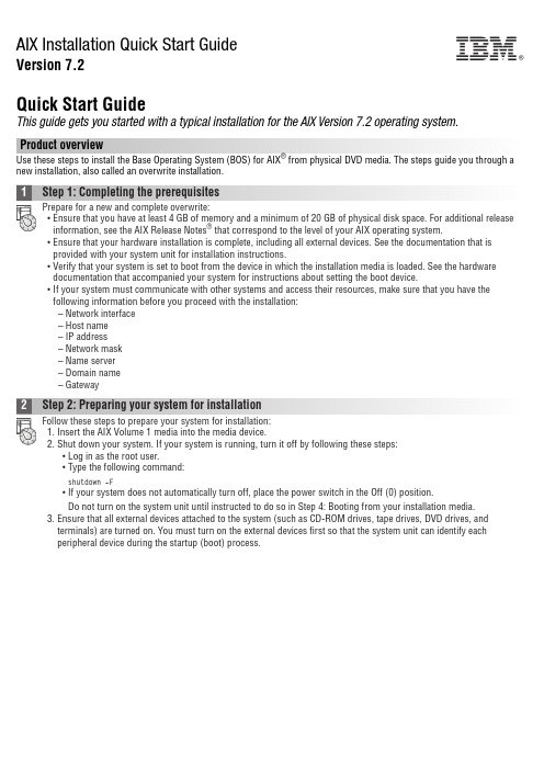
AIX Installation Quick Start GuideVersion 7.2Quick Start GuideThis guide gets you started with a typical installation for the AIX Version 7.2 operating system.Product overviewUse these steps to install the Base Operating System (BOS) for AIX®from physical DVD media. The steps guide you through a new installation, also called an overwrite installation.1Step 1: Completing the prerequisitesPrepare for a new and complete overwrite:v Ensure that you have at least 4 GB of memory and a minimum of 20 GB of physical disk space. For additional release information, see the AIX Release Notes®that correspond to the level of your AIX operating system.v Ensure that your hardware installation is complete, including all external devices. See the documentation that is provided with your system unit for installation instructions.v Verify that your system is set to boot from the device in which the installation media is loaded. See the hardware documentation that accompanied your system for instructions about setting the boot device.v If your system must communicate with other systems and access their resources, make sure that you have the following information before you proceed with the installation:–Network interface–Host name–IP address–Network mask–Name server–Domain name–Gateway2Step 2: Preparing your system for installationFollow these steps to prepare your system for installation:1.Insert the AIX Volume 1 media into the media device.2.Shut down your system. If your system is running, turn it off by following these steps:v Log in as the root user.v Type the following command:shutdown-Fv If your system does not automatically turn off, place the power switch in the Off (0) position.Do not turn on the system unit until instructed to do so in Step 4: Booting from your installation media.3.Ensure that all external devices attached to the system (such as CD-ROM drives, tape drives, DVD drives, andterminals) are turned on. You must turn on the external devices first so that the system unit can identify eachperipheral device during the startup (boot) process.IBM®3Step 3: Setting up an ASCII terminalIf you have not set up ASCII terminal, set the communications, keyboard, and display options. Use the following criteriaand your terminal reference documentation to set the communications, keyboard, and display options. The following settings are typical, but your terminal might have different option names and settings than those listed here:Communication Options:Options SettingsLine speed(baud rate)9600Word Length(bits per character)8Parity no(none)Number of stop bits1Interface RS-232C(or RS-422A)Line control IPRTSKeyboard and display options:Options SettingsScreen normalRow and Column24x80Scroll jumpAuto LF(line feed)offLine Wrap onForcing Insert line(or both)Tab fieldOperating Mode echoTurnaround Character CREnter returnReturn new lineNew Line CRSend pageInsert Character space4Step 4: Booting from your installation mediaFollow this procedure for booting from your installation media:1.Turn on the system unit power switch.2.When the system beeps twice, press 5 on your ASCII terminal. The word keyboard is shown when the beeps occur.3.If you have more than one console, each one might display a panel that directs you to press a key to identify yoursystem console. A different key is specified for each console that is displayed on this panel. If this panel opens, press the specified key only on the console that you want to use for the installation. (The system console is the keyboard and display device that is used for installation and system administration.)4.Select the language that you prefer to use during installation, and press Enter.5Step 5: Verifying the installation settingsFollow this procedure to verify your installation settings:1.Display the installation settings before you install the BOS, by typing 2 in the Choice field to select 2 Change/Show2.Verify the default installation settings from the Overwrite Installation and Settings panel.3.If the installation and system settings are correct, type 0 in the Choice field and press Enter. Confirm that theselections on the installation summary panel are correct, and press Enter to begin the BOS installation. The system automatically reboots after the system installation is complete. Go to Step 9: Finishing the BOS installation.If your installation settings are not correct, or if you want to change the installation settings, go to Step 6. Changing the installation settings.6Step 6: Optional: Changing the installation settingsTo change the installation settings, complete the following steps:1.2.When the Change Method of Installation panel is displayed, type 1 for New and Complete Overwrite Installation andpress Enter.When the Change Disk(s) Where You Want to Install panel is displayed, you can change the destination disk for the3.If the default settings shown are correct, type 0 in the Choice field and press Enter.To change the destination disk, complete the following steps:a.Type the number for each disk where you want to install the BOS in the Choice field and press Enter. Do not pressEnter a final time until you finish selecting all disks. If you must deselect a disk, type its number a second time andpress Enter.b.To finish selecting disks, type 0 in the Choice field and press Enter. The Installation and Settings panel is displayedwith the selected disks listed under System Settings.7Step 7: Changing Primary Language EnvironmentTo change the primary language that is used by this installation:1.Type 2 Primary Language Environment®Settings in the Choice field on the Installation and Settings panel.2.Select the appropriate set of cultural convention, language, and keyboard options. Most of the options are apredefined combination; however, you can define your own combination of options.3.To select a predefined Primary Language Environment, type the corresponding number in the Choice field and pressEnter.To configure your own Primary Language Environment, complete the following steps:a.Select More Choices.b.Page through the choices and select the Create Your Own Combination option.c.On the Set Primary Cultural Convention panel, type the corresponding number in the Choice field and press Enter.d.On the Set Primary Language panel, type the number in the Choice field that corresponds to your choice for theprimary language and press Enter.e.On the Set Keyboard panel, type the number in the Choice field that corresponds to the keyboard that is attachedto the system and press Enter.8Step 8: Verifying BOS installation settingsTo verify your BOS installation settings:1.2.Press Enter to begin the BOS installation.9Step 9: Finishing the BOS installationAfter the base runtime environment is installed, status information is displayed about other software that is beinginstalled. The system automatically reboots.The Installation Assistant guides you through the configuration tasks.Related informationFor more information about installing AIX, see the following resources:v For additional release information, see the AIX Release Notes that corresponds to your level of the AIX operatingsystem in the IBM®Knowledge Center (/support/knowledgecenter/ssw_aix_72/com.ibm.aix.base/ releasenotes_kickoff.htm).v For more detailed installation documentation, see the AIX Version 7.2 installation and migration topic collection in the IBM Knowledge Center (/support/knowledgecenter/ssw_aix_72/com.ibm.aix.install/insgdrf-kickoff.htm).AIX Version 7.2 Licensed Materials - Property of IBM. © Copyright IBM Corp. 2015. U.S. Government Users Restricted Rights - Use, duplication or disclosure restricted by GSA ADP Schedule Contract with IBM Corp.IBM, the IBM logo, and ®are trademarks or registered trademarks of International Business Machines Corp., registered in many jurisdictions worldwide. Other product and service names might be trademarks of IBM or other companies. A current list of IBM trademarks is available on the web at “Copyright and trademark information” (/legal/copytrade.shtml).Document Number:SA23-2267-03Printed in USA。
Fusion Center Accessory Shelf FCA820 821 安装说明书
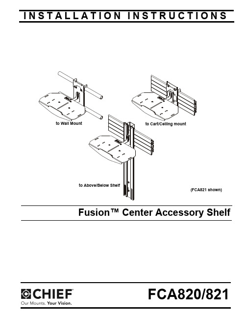
I N S T A L L A T I O N I N S T R U C T I O N SFusion™ Center Accessory ShelfFCA820/821FCA820/821Installation Instructions2DISCLAIMERMilestone AV Technologies and its affiliated corporations and subsidiaries (collectively “Milestone”), intend to make thismanual accurate and complete. However, Milestone makes no claim that the information contained herein covers all details,conditions or variations, nor does it provide for every possible contingency in connection with the installation or use of this product. The information contained in this document is subject to change without notice or obligation of any kind. Milestone makes no representation of warranty, expressed or implied,regarding the information contained herein. Milestone assumes no responsibility for accuracy, completeness or sufficiency of the information contained in this document.Chief® is a registered trademark of Milestone AV Technologies.All rights reserved.IMPORTANT SAFETY INSTRUCTIONSWARNING: A WARNING alerts you to the possibility ofserious injury or death if you do not follow the instructions.CAUTION: A CAUTION alerts you to the possibility ofdamage or destruction of equipment if you do not follow the corresponding instructions.WARNING:Failure to read, thoroughly understand, andfollow all instructions can result in serious personal injury,damage to equipment, or voiding of factory warranty! It is the installer’s responsibility to make sure all components are properly assembled and installed using the instructions provided.WARNING:Exceeding the weight capacity can result inserious personal injury or damage to equipment! It is the installer’s responsibility to make sure the combined weight mounted to the FCA820/821 shelves does not exceed 10 lbs (4.5 kg).WARNING:Use this mounting system only for its intendeduse as described in these instructions. Do not use attachments not recommended by the manufacturer.WARNING:Never operate this mounting system if it isdamaged. Return the mounting system to a service center for examination and repair.WARNING:Do not use this product outdoors.WARNING:RISK OF INJURY TO PERSONS! Do not usethis mounting system to support video equipment such as televisions or computer monitors.--SAVE THESE INSTRUCTIONS--Installation Instructions FCA820/821 DIMENSIONS - FCA8203FCA820/821Installation Instructions DIMENSIONS - FCA820 (CONTINUED)DIMENSIONS - FCA8214Installation Instructions FCA820/821 DIMENSIONS - FCA821 (CONTINUED)5FCA820/821Installation Instructions6LEGENDTOOLS REQUIRED FOR INSTALLATIONPARTSApretar elemento de fijación Befestigungsteil festziehen Apertar fixador Serrare il fissaggio Bevestiging vastdraaien Serrez les fixations Aflojar elemento de fijación Befestigungsteil lösen Desapertar fixador Allentare il fissaggio Bevestiging losdraaien Desserrez les fixations Llave de cabeza hexagonal Sechskantschlüssel Chave de cabeça sextavada Chiave esagonale ZeskantsleutelClé à tête hexagonaleDestornillador Phillips Kreuzschlitzschraubendreher Chave de fendas Phillips Cacciavite a stella Kruiskopschroevendraaier Tournevis à pointe cruciforme Llave de boca Gabelschlüssel Chave de bocas Chiave a punte aperte Steeksleutel Clé à fourcheInstallation Instructions FCA820/8217ASSEMBLY AND INSTALLATION Installing to Cart/Ceiling MountNOTE:If installing to Wall Mount, proceed to "Installing to WallMount" Section. If installing to a FCA810/811 shelf,proceed to "Installing to FCA810/811 Shelves" section.1.Attach FCA820/821 shelf (A) to center plate (B) using two #10-32 x 1/4” button head cap screws (D) and two #10washers (K). (See Figure 1)Figure 12.Use two 1/4-20 x 3/8” button head cap screws (C) and two 1/4” washers (J) to attach one center holder (F) to center plate (B). (See Figure 2)Figure 23.Place center holder (F) on top of cart interface. (See Figure 3)4.Place second center holder (F) underneath cart interface so that mounting holes are aligned. (See Figure 3)Figure 35.Use two 1/4-20 x 3/8” button head cap screws (C) and two 1/4” washers (J) to attach the other center holder (F) toFigure 4FCA820/821Installation Instructions8Installing to Wall Mount1.Attach FCA820/821 shelf (A) to center plate (B) using two #10-32 x 1/4” button head cap screws (D) and two #10washers (K). (See Figure 5)Figure 52.Use two 1/4-20 x 1 1/4” button head cap screws (G) and two 1/4” washers (J) to partially attach one center holder (F) to center plate (B). Do NOT install screws too far or installation to wall mount will not be possible. (See Figure 6)Figure 63.Place center holder (F) on top of wall mount rail. (See Figure 7)4.Tighten two screws (G) holding center holder (F) to center plate (B). (See Figure 7)5.Place second center holder (F) underneath wall mount rail so that mounting holes are aligned. (See Figure 7)Figure 76.Use two 1/4-20 x 1 1/4” button head cap screws (G) and two 1/4” washers (J) to attach the other center holder (F) to center plate (B). (See Figure 8)Figure 8Installation Instructions FCA820/8219Installing to FCA810/811 ShelvesNOTE:FCA820/821 may be attached to FCA810/811 Above/Below Shelves.1.Install FCA810/811 shelf to mount following FCA810/811installation instructions.2.Use two #10-32 x 1/4” button head cap screws (D) and two WARNING:serious personal injury or damage to equipment! It is the installer’s responsibility to make sure the all components located on the 10 lbs (4.5 kg).WARNING:using either adhesive hook and loop squares (E) or screws (H or N)! Failure to securely mount camera to shelf may result in serious personal injury or damage to equipment!NOTE:Using Adhesive Squares1.Use up to eight adhesive hook and loop squares (E) to secure camera to shelf. Attach adhesive squares to bottom of camera first and then attach corresponding squares to shelf when the exact mounting location has been determined. (See Figure 10)Using Screw(s)NOTE:2.(Single Screw option) Install 1/4-20 x 3/8” Phillips panmachine screw (H) through mounting slot on shelf and into hole on bottom of camera. (See Figure 10)3.(Multiple screw option - FCA821 only) Install four #4-48 x 1/4” Phillips pan machine screws (N) through outside mounting slots and into holes on bottom of camera. (See Figure 11)4.Route cable from camera towards back of shelf and down behind the FCA820/821. (See Figure 10) and (See Figure 11)Figure 11FCA820/821Installation Instructions 10Installation Instructions FCA820/82111FCA820/821Installation Instructions USA/International A 6436 City West Parkway, Eden Prairie, MN 55344P 800.582.6480 / 952.225.6000F 877.894.6918 / 952.894.6918Europe A Franklinstraat 14, 6003 DK Weert, Netherlands P +31 (0) 495 580 852F +31 (0) 495 580 845Asia Pacific A Office No. 918 on 9/F, Shatin Galleria 18-24 Shan Mei Street Fotan, Shatin, Hong Kong P 852 2145 4099F 852 2145 4477Chief, a products division of Milestone AV Technologies 8800-002586 Rev002014 Milestone AV Technologies 05/14。
安装使用说明书PAS900

目
录
一.安装使用指南 ............................................................................................................................ 3
1.产品概述.................................................................................................................................. 3 2.产品规格及功能表(见表 1) ....................................................................................................3 3.技术指标.................................................................................................................................. 4 4.产品安装.................................................................................................................................. 4 5.面板介绍.................................................................................................................................... 5 6.接线方法.................................................................................................................................... 6 7.操作介绍.................................................................................................................................... 6
6-BPS软件安装说明V1.0

BPS软件安装说明(V4.0/V4.1)------BPS:BEEcube Platform Studio ------------------------------------版本信息---------------------------------------初始版本:V1.0初始日期:2013.07.11编写人员:XD修改日期:----------------------------------------------------------------------------------------1、系统要求The MathworksMatlab/Simulink R2010bXilinxISE 12.4EDK 12.4System Generator for DSP 12.4Mentor Graphics(optional)ModelSim 6.6c说明:BPS支持32位或64位windows操作系统,64位Linux操作系统。
此时BPS的版本为:BPSv40rc12_r20120323_installer,按照如上的软件版本要求安装,如果版本不同,会出现不兼容的情况。
注意:BPSv40rc12_r20120323_installer不支持ISE13.4,不支持Matlab R2011a。
该版本的chipscope调用BEEcube遇到error:ERROR:Client version ’12.1’is not supported by server version ’13.1’.Cannot open new session.2、软件安装(1)Matlab完整安装Matlab R2010b,确保Matlab和simulink正常使用。
具体安装步骤可详见安装目录中安装说明。
添加path变量:path {Matlab_installation_path}\MATLAB\R2010b\bin(2)Xilinx完整安装ISE_DS 12.4,确保ISE和EDK正常使用。
SBA ProConnect 7.2 版本发布说明书
Release Notes ContentsVersion 7.2 3 SBA ProConnect Table of Contents1 Features (7)1.1 Version 7.2.15 (7)1.1.1 Add Bios and Disk Information (7)1.2 Version 7.2.12 (7)1.2.1 Support for Windows Server 2016 (7)1.3 Version 7.2.11 (8)1.3.1 Display the CU Component in SBA List .................................................................... 8 1.3.2 Auto Synchronization of SBA after Task ................................................................... 8 1.3.3 Synchronize a Single SBA ......................................................................................... 8 1.3.4 Change Date Format . (8)1.4 Version 7.2.0 (9)1.4.1 Security Support ........................................................................................................ 9 1.4.2 Remove Install Files .................................................................................................. 9 1.4.3 Skype for Business Support .. (9)2 Resolved Constraints (11)2.1 Version 7.2.15 (11)2.2 Version 7.2.11 ...................................................................................................... 11 3Known Constraints ........................................................................................... 13 3.1 Version 7.2 ........................................................................................................... 13 4Upgrade Procedure (15)SBA ProConnectRelease Notes 4Document #: LTRT-38945 This page is intentionally left blank.Release Notes NoticesVersion 7.2 5 SBA ProConnect NoticeInformation contained in this document is believed to be accurate and reliable at the time of printing. However, due to ongoing product improvements and revisions, AudioCodes cannot guarantee accuracy of printed material after the Date Published nor can it accept responsibility for errors or omissions. Updates to this document can be downloaded from https:///library/technical-documents.This document is subject to change without notice.Date Published: June-03-2019WEEE EU DirectivePursuant to the WEEE EU Directive, electronic and electrical waste must not be disposed of with unsorted waste. Please contact your local recycling authority for disposal of this product. Customer SupportCustomer technical support and services are provided by AudioCodes or by an authorized AudioCodes Service Partner. For more information on how to buy technical support for AudioCodes products and for contact information, please visit our Web site at https:///services-support/maintenance-and-support .Abbreviations and TerminologyEach abbreviation, unless widely used, is spelled out in full when first used.SBA ProConnectRelease Notes 6Document #: LTRT-38945 Related DocumentationDocumentation FeedbackAudioCodes continually strives to produce high quality documentation. If you have any comments (suggestions or errors) regarding this document, please fill out the Documentation Feedback form on our Web site at https:///documentation-feedback ..Release Notes 1. Features Version 7.2 7 SBA ProConnect1Features 1.1Version 7.2.15 1.1.1 Add Bios and Disk InformationBios information (version and date) has been added to the SBA Server Details page.After upgrading to this version, perform SBA synchronization to retrieve the new information from the SBA Server List.1.2Version 7.2.12 1.2.1 Support for Windows Server 2016This version supports the Windows Server 2016 platform. The installation procedureincludes an additional procedure for installing IIS.SBA ProConnectRelease Notes 8Document #: LTRT-38945 1.3Version 7.2.11 1.3.1 Display the CU Component in SBA ListThe SBA ProConnect Management Interface supports viewing of the SBA server Skype for Business/Lync version from the SBA servers list without the need to open the SBA Details page. Hovering over the SBA version column displays a tooltip with details of the SBA Skype for Business/Lync versions.1.3.2 Auto Synchronization of SBA after TaskAfter the CU update task ends successfully, the SBA ProConnect server retrieves the new SfB/Lync component details and updates the SBA server details.1.3.3 Synchronize a Single SBAThe SBA ProConnect Management Interface supports synchronization of a single SBA server separately from the SBA servers list page.1.3.4 Change Date FormatThe SBA Pro Connect also supports American date format: month/day/year. The default setting of the SBA ProConnect uses European format. New configuration values are used to determine the date format of the SBA ProConnect. It is required to restart the SBA ProConnect Service after making changes in configuration file. New configuration values are updated as follows:C:\Program Files\Audiocodes\ProConnectService\Config\System.config: phpDateFormat: The date format that be used by GUI PHP part. American format: m-d-Y H:i European format(default): d/m/Y H:i jsDateFormat: The date format that be used by GUI Java script part American format: MM-DD-YYYY hh:mm European format(default): DD/MM/YYYY HH:mm pickerDateFormat: The date format that be used by GUI picker component American format: mm-dd-yyyy hh:ii European format(default): dd/mm/yyyy hh:iiRelease Notes 1. FeaturesVersion 7.2 9 SBA ProConnect1.4Version 7.2.0 1.4.1 Security SupportThe ProConnect server now supports an HTTPS connection with SBA servers (for events and install file download operations).1.4.2 Remove Install FilesInstall files can now be removed from the SBA ProConnect server. A new page in the SBA Management Interface "Install File List" enables this action to be performed. The removal action also deletes the file from the disk.1.4.3Skype for Business Support The ProConnect server now supports an upgrade from Lync 2010 server and Lync 2013 server to Skype for Business server.SBA ProConnectRelease Notes 10Document #: LTRT-38945 This page is intentionally left blank.Release Notes 2. Resolved Constraints Version 7.2 11 SBA ProConnect2Resolved Constraints 2.1 Version 7.2.15This release includes the following resolved constraint:⏹ The SBA device cannot download .part11 file from the SBA ProConnect server– Thisproblem is due to a missing mime type configuration value in the IIS Manager, WIM slices with extension ‘.part11’ , ‘.part12’.2.2 Version 7.2.11This release includes the following resolved constraint:⏹ SBA Server Details – CU List is broken In Skype for Business systems, the lines in thelist of ‘Component Versions’ in SBA details page is truncated. The fix uses different method to retrieve the CU list from the OS.SBA ProConnectRelease Notes 12Document #: LTRT-38945 This page is intentionally left blank.Release Notes 3. Known Constraints Version 7.2 13 SBA ProConnect3Known Constraints 3.1 Version 7.2This release includes the following known constraints:⏹ When upgrading, the following message may appear; select Repair option and Next .⏹Only Windows Imaging File Format (wim) installation image files can be used with the ProConnect server. Other SBA image formats cannot be used. ⏹Currently SBA ProConnect only supports the Mediant 800B and Mediant 1000B products. ⏹SBA ProConnect SBA list Synchronization takes several minutes, during which time the SBA ProConnect GUI is locked. ⏹ The SBA ProConnect installation does not include any CU or SBA software image. Touse these files in the system, the administrator must download them from the AudioCodes Web site and copy them manually to the ProConnect server at: c:\Proconnect\InstallFile folder.⏹ The Download task does not apply to CU files – Only OS burn images (Lync 2010 andLync 2013 images) can be applied in the Download task.⏹ Non-secure HTTPS Webadmin access is enabled by default. Enabling secure accessto the Webadmin requires further IIS configuration and certificate signing.⏹ The SBA setup must be completed manually after the burn operation when running atask to upgrade the OS image from Lync 2010 to Lync 2013 or SfB.SBA ProConnectRelease Notes 14Document #: LTRT-38945 ⏹ The administrator must move the SBA users to another Skype for Business poolbefore commencing the OS upgrade procedure and return them after completing the new SBA configuration in the new image.⏹ Only 10 simultaneous download operations can be performed. When a task has morethan 10 SBA servers to perform downloads, the download operation for the additional SBA’s only occurs once resources are freed.⏹ When a task has been terminated manually by the administrator, it can take up to onehour until the SBAs assigned to this task can be reassigned to a new task. Therefore, such an SBA should not be assigned to a new task for at least one hour.⏹ If there is no network connection between the SBA and the SBA ProConnect serverwhen a CU or OS burn task is started on the ProConnect server, the SBA is marked as “failed” in the task result. In this case, the SBA needs to be assigned to a new task altogether.Release Notes 4. Upgrade Procedure 4 Upgrade ProcedureThis section describes how to upgrade the SBA ProConnect server.To upgrade SBA ProConnect:1. Download the file ProConnectWixBootstrapper_7.2.14 from:https:///services-support/maintenance-and-support2. On the SBA ProConnect server, stop the ProConnect service before running setup.3. Run the setup and verify that it is completes successfully.4. After the setup, verify that the service “SBA ProConnect Service” is running.5. Login to the SBA ProConnect Web at https://<ip_of_server>/webadmin/login.php.6. Synchronize the SBA List.7. Schedule several tasks and verify that these actions are successful.Version 7.2 15 SBA ProConnectInternational Headquarters1 Hayarden Street,Airport CityLod 7019900, IsraelTel: +972-3-976-4000Fax: +972-3-976-4040AudioCodes Inc.200 Cottontail LaneSuite A101ESomerset NJ 08873Tel: +1-732-469-0880Fax: +1-732-469-2298Contact us: https:///corporate/offices-worldwideWebsite: https:///©2019 AudioCodes Ltd. All rights reserved. AudioCodes, AC, HD VoIP, HD VoIP Sounds Better, IPmedia, Mediant, MediaPack, What’s Inside Matters, OSN, SmartTAP, User Management Pack, VMAS, VoIPerfect, VoIPerfectHD, Your Gateway To VoIP, 3GX, VocaNom, AudioCodes One Voice and CloudBond are trademarks or registered trademarks of AudioCodes Limited. All other products or trademarks are property of their respective owners. Product specifications are subject to change without notice.Document #: LTRT-38945。
Siemens S7-1200 PLC 安装指南说明书
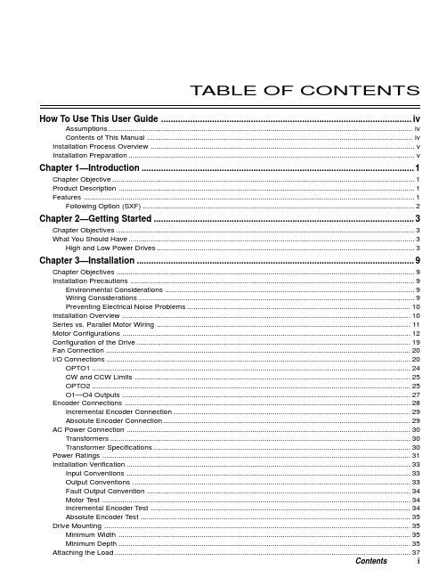
T ABLE OF CONTENTS How To Use This User Guide (iv)Assumptions (iv)Contents of This Manual (iv)Installation Process Overview (v)Installation Preparation (v)Chapter 1—Introduction (1)Chapter Objective (1)Product Description (1)Features (1)Following Option (SXF) (2)Chapter 2—Getting Started (3)Chapter Objectives (3)What You Should Have (3)High and Low Power Drives (3)Chapter 3—Installation (9)Chapter Objectives (9)Installation Precautions (9)Environmental Considerations (9)Wiring Considerations (9)Preventing Electrical Noise Problems (10)Installation Overview (10)Series vs. Parallel Motor Wiring (11)Motor Configurations (12)Configuration of the Drive (19)Fan Connection (20)I/O Connections (20)OPTO1 (24)CW and CCW Limits (25)OPTO2 (25)O1—O4 Outputs (27)Encoder Connections (28)Incremental Encoder Connection (29)Absolute Encoder Connection (29)AC Power Connection (30)Transformers (30)Transformer Specifications (30)Power Ratings (31)Installation Verification (33)Input Conventions (33)Output Conventions (33)Fault Output Convention (34)Motor Test (34)Incremental Encoder Test (34)Absolute Encoder Test (35)Drive Mounting (35)Minimum Width (35)Minimum Depth (35)Attaching the Load (37)Contents iCouplings (37)Tuning (38)Resonance (38)Mid-Range Instability (38)Tuning Procedures (38)Motor Waveforms (40)Anti-Resonance (40)Chapter 4—Application Design (41)Chapter Objectives (41)Motion Profile Application Considerations (41)Preset Mode Moves (42)Incremental Mode Preset Moves (42)Absolute Mode Preset Moves (42)Continuous Mode Moves (43)Closed Loop Operation (44)Setting Encoder Resolution (45)Encoder Step Mode (45)Motion Programs and Sequences (56)Sequence Commands (56)Creating and Executing Sequences (58)Subroutines (59)Sequence Debugging Tools (63)High-Level Programming Tools (67)Complex Branching and Looping (70)Conditionals (71)Error Flag (75)Branching Using Variables and Boolean Logic (76)Motion Profiling Mode—On-the-Fly Changes (77)Interfacing to the SX (81)Programmable Inputs and Outputs (81)PLC Operation (94)Rotary vs. Linear Indexers (97)Chapter 5—SXF Follower (99)Chapter Objectives (99)What is Following? (99)Types of Following (100)Velocity Following (100)Position and Velocity Following (103)Recede and Advance While Following (115)Synchronization (132)Other Following Features (135)Following Equation and Command Summary (137)Chapter 6—Hardware Reference (143)Chapter Objectives (143)Environmental Specifications (143)Drive Electrical Specifications (143)I/O Electrical Specifications (144)Motor Electrical Specifications (147)Operational Specifications (147)Motor Current & Torque (148)Drive Dimensions (149)Motor Dimensions (150)DIP Switch Summary (152)Non-Compumotor—Drive/Motor Connection (155)Wiring Configurations.............................................................................................................................155, 156 Terminal Connections. (157)Non-Compumotor Motors—Setting Motor Current (158)Motor Performance Specifications (158)ii SX/SXF Indexer/Driver User GuideChapter 7—Maintenance & Troubleshooting (161)Chapter Objectives (161)Maintenance (161)Battery Maintenance (161)Drive Maintenance (161)Motor Maintenance (162)Common Problems and Solutions (163)Software Debugging Tips (165)Returning the System (167)Appendices (169)Command Listing (169)SX Example Programs (171)Appendix C—LVD Installation Instructions (175)Complying with the Low Voltage Directive (LVD) (175)Additional Installation Procedures for LVD Compliance (175)Table of Graphic Symbols and Warnings (177)Index (179)Contents iiiHow To Use This User GuideThis user guide is designed to help you install, develop, and maintain your system. Each chapterbegins with a list of specific objectives that should be met after you have read the chapter. Thissection is intended to help you find and use the information in this user guide. AssumptionsThis user guide assumes that you have the skills or fundamental understanding of the followinginformation.t Basic electronics concepts (voltage, switches, current, etc.)t Basic motion control concepts (torque, velocity, distance, force, etc.)Contents of This ManualThis user guide contains the following information.Chapter 1:IntroductionThis chapter provides a description of the product and a brief account of its specific features.Chapter 2:Getting StartedThis chapter contains a detailed list of items you should have received with your SX shipment. Itwill help you to become familiar with the system and ensure that each component functions properly.Chapter 3:InstallationThis chapter provides instructions for you to properly mount the system and make all electricalconnections. Upon completion of this chapter, your system should be completely installed and readyto perform basic operations. Tuning considerations and procedures are also provided.Chapter 4:Application DesignThis chapter will help you customize the system to meet your application’s needs. Importantapplication considerations are discussed. Sample applications are provided.Chapter 5:SXF FollowerThis chapter explains the SXF Following function and the SXF’s capability to support absolute andincremental encoders.Chapter 6:Hardware ReferenceThis chapter contains information on system specifications (electrical, dimensions, and perfor-mance). It may be used as a quick-reference tool for proper switch settings and connections.Chapter 7:TroubleshootingThis chapter contains information on identifying and resolving system problems.iv SX/SXF Indexer/Driver User GuideInstallation Process OverviewTo ensure trouble-free operation, pay special attention to the environment in which the SX equip-ment will operate, the layout and mounting, and the wiring and grounding practices used. Theserecommendations are intended to help you easily and safely integrate SX equipment into yourmanufacturing facility. Industrial environments often contain conditions that may adversely affectsolid-state equipment. Electrical noise or atmospheric contamination, may also affect the SXSystem.Developing Your ApplicationBefore you attempt to develop and implement your application, there are several issues that youshould consider and address.Recognize and clarify the requirements of your application. Clearly define what you expect the system todo.Assess your resources and limitations. This will help you find the most efficient and effective means ofdeveloping and implementing your application (hardware and software).Follow the guidelines and instructions outlined in this user guide. Do not skip any steps or procedures.Proper installation and implementation can only be ensured if all procedures are completed in the propersequence.Installation PreparationBefore you attempt to install this product, you should complete the following steps:Review this entire user guide. Become familiar with the user guide’s contents so that you can quickly findthe information you need.Develop a basic understanding of all system components, their functions, and interrelationships.Complete the basic system configuration and wiring instructions (in a simulated environment, not apermanent installation) provided in Chapter 2, Getting Started.Perform as many basic functions as you can with the preliminary configuration. You can only perform thistask if you have reviewed the entire user guide. You should try to simulate the task(s) that you expect toperform when you permanently install your application (however, do not attach a load at this time). Thiswill give you a realistic preview of what to expect from the complete configuration.After you have tested all of the system’s functions and used or become familiar with tll of the system’sfeatures, carefully read Chapter 3, Installation.After you have read Chapter 3 and clearly understand what must be done to properly install the system,you should begin the installation process. Do not deviate from the sequence or installation methodsprovided.Before you begin to customize your system, check all of the systems functions and features to ensure thatyou have completed the installation process correctly.The successful completion of these steps will prevent subsequent performance problems and allowyou to isolate and resolve any potential system difficulties before they affect your system’soperation.ConventionsTo help you understand and use this user guide effectively, the conventions used throughout this userguide are explained in this section.CommandsAll commands that you are instructed to enter are shown in capital letters. The symbol >, is the SXcommand prompt. The command is displayed in boldface. A delimiter (space or carriage return) isrequired after each command. A description is provided next to each command example.Command Description>MR Sets motor resolution to 25,000 steps/revThe system ignores command syntax that is not within the valid range for a specific command. A ?prompt will be returned by the drive when the last command entered was not understood, or aparameter limit was exceeded.Contents vMotorsS Series and SX Series motors are one in the same (interchangeable terms).Warnings & CautionsWarning and caution notes alert you to possible dangers that may occur if you do not follow instruc-tions correctly. Situations that may cause bodily injury are present as warnings. Situations that maycause system damage are presented as cautions. These notes will appear in bold face and the wordwarning or caution will be centered and in all capital letters. Refer to the examples shown below:WARNINGDo not touch the motor immediately after it has been in use for an extended period of time. The motormay be hot.CAUTIONSystem damage will occur if you power up the system improperly.Related Publicationst Current Parker Compumotor Motion Control Catalogt SX Indexer/Drive Software Reference Guidevi SX/SXF Indexer/Driver User Guide。
Xpass 安装指南说明书
INSTALLATION GUIDEXpassEnglishVersion 2.10EN 101.00.XPS V2.10AContentsSafety Instructions (3)Getting Started (4)Components (4)Features (5)Part names and features (5)Cables and connectors (6)Installation (7)Mounting the Bracket and Product (7)Installing the bracket (7)Connecting to Power (8)Connecting to a Network (9)TCP/IP (9)Connecting to an Door button/Door sensor (10)Digital input connection (Door button, Door sensor) (10)Digital input connection (Alarm, Emergency switch) (10)Connecting to a R elay (11)Fail Safe Lock (11)Fail Secure Lock (11)Connecting to an Automatic door (12)Connecting as a standalone (12)Connecting to Secure I/O 2 (13)Connecting as a Wiegand device (13)External Power Output (14)Resetting Network Settings (14)Product Specifications (15)Dimensions (16)FCC Compliance Information (17)Appendix (18)Disclaimers (18)Copyright Notice (18)Safety InstructionsSafety InstructionsPlease read the following instructions carefully before using the product. This information is important for ensuring the safety of the user and for preventing damage to the user's property.WarningViolation of the instructions may cause serious injury or death.Installation InstructionsDo not install the product in direct sunlight or in a location that is damp or dusty.•This can cause a fire or electric shock.Install the product in a dry place.•Moisture can cause product damage or electric shock.Do not install the product near any heat source such as electric heaters.•This can cause a fire from overheat or electric shock.Install the product in a place where there is no electromagnetic interference.•This can cause product damage or electric shock.Have qualified service professionals install or repair the product.•Otherwise, it can cause a fire, electric shock, or injury.•If the product is damaged due to a user's unauthorized installation or dismantling of the product, a service fee will be charged for repair.Operating InstructionsBe careful not to spill any liquid such as water, drinks, or chemicals inside the product.•This can cause fire, electric shock, or product damage.CautionIgnoring these instructions may result in minor injuries or damage to the product.Installation InstructionsProtect the power cord from being walked on or pinched.•This can cause product damage or injury.Keep the product away from strong magnetic objects such as magnets, TVs, monitors (especially CRT monitors), or speakers. •This can cause a product failure.If installing the product outside where the product is completely exposed, it is recommended to install the product together with the enclosure.Use a separate power supply for Secure I/O 2, electric lock and Xpass respectively.•If connecting and using the power supply to these devices together, the devices may malfunction.Operating InstructionsDo not drop the product or subject it to shock or impact during use.•This can cause a product failure.Do not press the buttons on the product with excessive force or with a sharp tool.•This can cause a failure.Clean the product with a soft, dry cloth. Do not use alcohol, benzene, or water.•This can cause a product failure.Getting StartedComponentsThe components may differ depending on where the product is installed.NoteXpassMain bracketAdapterMounting screws for bracket(2 pcs) PVC anchors (2 pcs) Heat shrink tubesSoftware CDDiodeExtension bracketTCP/IPextension cableFeaturesPart names and featuresNameFeatureLED lamp• Green: Authentication success• Red: Authentication failure • Pink: Processing• Blue and sky-blue alternate flashing every 2 seconds: Normal operation • Red and pink alternate flashing every 2 seconds: The device is locked.• Blue and red alternate flashing every 2 seconds: The clock has been reset due to an empty internal battery. (The clock needs to be reconfigured.)• Blue and yellow alternate flashing every 2 seconds: An IP address has not been received when DHCP is set to USE.• Red flashes every 2 seconds on first use: Failure to reset. Contact the manufacturer. • Red flashes every 2 seconds in a normal operation: The device is secured. •Yellow flashes: Waiting for an input.RF card touch area Reads RF card for entering and exiting.Network reset button Resets the network configurations when the device does not work properly. For details, refer to the Resetting Network Setting .Cables and connectorsInstallationMounting the Bracket and ProductInstalling the bracket1With the mounting screws for the bracket, mount the bracket firmly onto the surface where Xpass is to be installed.If Xpass should be installed onto a concrete wall, make a hole with a drill, and then insert a PVC anchor into the hole before screwing the mounting screw.2Attach Xpass onto the mounted bracket.3Assemble Xpass with the bracket by screwing the mounting screws on the bottom of Xpass.NoteConnecting to Power•Use a power adapter that has a DC 12 V (± 10%) specification of with the minimum current of 1,500 mA and has IEC/EN 60950-1 certification. If the power adapter is shared by other devices, the power adapter should provide a current more than the sum of the power consumption from this device (1,500 mA) and other devices.• Use a separate power supply for Secure I/O 2, electric lock and Xpass respectively. If connecting and using the power supply to these devices together, the devices may malfunction.Note 14 - PWR +VDC Red16 - PWR GNDBlack (White stripe)UPS (Optional)DC powerXpass1614Connecting to a NetworkTCP/IPLAN connection (connecting to a hub)A normal CAT-5 cable can be used to connect to a hub.HubPCXpassLAN connection (connecting directly to a PC)Xpass can be connected directly to a PC by using a normal type CAT-5 cable because it supports an automatic MDI/MDIX function.PCXpassConnecting to an Door button/Door sensorDigital input connection (Door button, Door sensor)7 - TTL IN1 Brown9 - TTL GND Gray11 - TTL IN0 PurpleDoor sensor 97911Xpass Door buttonDigital input connection (Alarm, Emergency switch)7 - TTL IN1 Brown9 - TTL GND Gray11 - TTL IN0 PurpleInput 1 97911Xpass Input 0Connecting to a RelayFail Safe LockTo use fail safe lock, connect N/C terminal as shown below. Normally, there is a current flowing through the relay and the door is opened when the relay is activated by blocking current flows. The door is opened when there is a blackout or power failure caused by external conditions.• Install the diode at both ends of the wire for the door lock device as shown in the figure to protect the relay from being damaged by the reverse current induced when the door lock device operates.• Make sure that the direction of the installed diode is correct. • Install the diode close to the door lock device.•Use a separate power source for Xpass from the door lock device.Fail Secure LockTo use fail secure lock, connect N/O terminal as shown below. Normally, there is no current flowing through the relay and the door is opened when the relay is activated by a current flows. The door is locked when there is a blackout or power failure caused by external conditions.• Install the diode at both ends of the wire for the door lock device as shown in the figure to protect the relay from being damaged by the reverse current induced when the door lock device operates.• Make sure that the direction of the installed diode is correct. • Install the diode close to the door lock device.•Use a separate power source for Xpass from the door lock device.Note 8 - RLY NO Gray (White stripe) 10 - RL Y COMGreen (White stripe)Xpass8 10Deadbolt /Door strikeDC powerNote 10 - RL Y COM Green (White stripe) 12 - RLY NCOrange (Black stripe)XpassDeadbolt / Door strikeDC power10 12Connecting to an Automatic doorConnecting as a standaloneDoor buttonDoor sensorDoor lockInput 1RelayInput 09 7 12 10 911Xpass9 - TTL GND Gray 11 - TTL IN0 Purple 7 - TTL IN1 Brown10 - RL Y COM Green (White stripe) 12-RLY NCOrange (Black stripe)PC8 - RLY NO Gray (White stripe) 10 - RL Y COMGreen (White stripe)XpassSensorAutomatic door controllerDoor buttonDoor lock8 10Connecting to Secure I/O 2Refer to the following figure for connecting.• RS-485 should be AWG24, twisted pair, and maximum length is 1.2 km.• Connect a termination resistor (120Ω) to both ends of a RS-485 daisy chain connection. It should be installed at both endsof the daisy chain. If it is installed in the middle of the chain, the performance in communicating will deteriorate because it reduces the signal level. • Up to 32 devices can be connected via daisy chain (1 master device and 31 other devices).Connecting as a Wiegand deviceRFID reader2 - WG GND Black 4 - WG D1 White 6 - WG D0Green2 4 62 4 6ControllerXpassXpass Door lockInput 1Door buttonDoor sensorInput 05 3 11 - 485 GND White (Black stripe) 5 - 485 TRXP Blue (White stripe) 3 - 485 TRXNYellow (Black stripe)PCXpassSecure I/O 2External Power Output• The external output provides a maximum current of 620 mA. • Xpass connected to PoE supports the external power output.• Be careful not to disconnect the power supply to Xpass when the external power output is connected to a door lock. Disconnecting the power supply to Xpass may cause security problems.•The maximum switching current of the door lock should not exceed 620 mA. For more information on the maximum switching current of the door lock, contact the manufacturer.Resetting Network Settings1 Turn the power on.2 Press the network reset button on the rear of device until the device restart automatically.3 Connect the device with default values. • TCP/IP address: 192.168.0.1 • Server mode: Not checked• RS-485: PC connection, 115200 bps4 Change the TCP/IP address or RS-485 information.5Turn the power off later on and then check the network setting is properly.Note 10 - RLY COM Green (White stripe) 12 - RLY NC Orange (Black stripe) 18 - PWR OUT Sky-blue20 - PWR GNDBlack (White stripe)XpassDeadbolt / Door strike10 12 18 20Product SpecificationsMain IP Rating IP65RF Card 125KHz EM, 125KHz HID Prox, 13.56MHz Mifare/DESFire Multi-Controller Yes (RF)Capacity Max. User (1:1) 40,000 Max. User (1:N) 40,000 Max. Text L og 50,000Interface TCP/IP YesRS-485 1chWiegand 1ch In or Out (Selectable) TTL Input 2 InputsRelay 1 RelayRelay Voltage Max. 24VDC Current Typ. 0.5A, Max. 1.0AHardware CPU 533MHz DSP Memory 16MB RAM + 8MB Flash LED Multi-ColorSound 16-bit Hi-Fi Operating Temp. -20°C ~ 50°CTamper YesPower 12VDCPoE Optional Dimensions (W x H x D mm) 45 x 130 x 27 Certification CE, FCC, KC, RoHSDimensions(Unit: mm)Front viewExtension bracketMain bracketSide viewFCC Compliance InformationFCC Compliance InformationTHIS DEVICE COMPLIES WITH PART 15 OF THE FCC RULES.Operation is subject to the following two conditions:(1) This device may not cause harmful interference, and(2) This device must accept any interference received, including interference that may cause undesired operation.Note: This equipment has been tested and found to comply with the limits for a Class B digital device, pursuant to part 15 of the FCC Rules. These limits are designed to provide reasonable protection against harmful interference in a residential installation. This equipment generates, uses, and can radiate radio frequency energy and, if not installed and used in accordance with the instructions, may cause harmful interference to radio communications. However, there is no guarantee that interference will not occur in a particular installation. If this equipment does cause harmful interference to radio or television reception, which can be determined by turning the equipment off and on, the user is encouraged to try to correct the interference by one or more of the following measures:•Reorient or relocate the receiving antenna.•Increase the separation between the equipment and receiver.•Connect the equipment into an outlet on a circuit different from that to which the receiver is connected.•Consult the dealer or an experienced radio/TV technician for help.Modifications not expressly approved by the manufacturer could void the user's authority to operate the equipment under FCC rules.Appendix AppendixDisclaimersThis document provides the information pertaining to Suprema's products. The right of use is granted only to the products that are covered by the sales agreement and conditions guaranteed by Suprema. Any license of intellectual property that is not dealt within this document is not granted.Suprema does not provide any warranty or liability of fitness or merchantability for a particular purpose and of infringement of patents, copyrights, or other intellectual properties, regarding the sales or use of Suprema's products.Do not use Suprema's products in either circumstances where people could be hurt or die as a consequence of malfunctions of the products or circumstances related to medical treatments, the rescue of lives, or life supports. If a user suffers an accident in one of the circumstances mentioned above, employees, subsidiaries, branches, partners, and distributors of Suprema are exempt from liability even when it is claimed that there is a significant fault in the design or production process, and also they are not liable for any direct or indirect cost or expenditure including legal costs.Suprema can change the standard and specification of its products anytime without notice in order to improve the stability, functions, or design of the products. Designers should keep in mind that the functions or explanations denoted as "to be implemented" or "not defined" can be changed anytime. Suprema will implement or define such items in the shortest possible time, and will not accept any liability for problems incurred including compatibility issues.Contact Suprema, sales representatives of Suprema, or local distributors in order to get the latest specifications before ordering products. Copyright NoticeSuprema has the copyright of this document. The rights of other product names, brands, and trademarks belong to individuals or organizations who own them. 。
BPS产品安装指南

目录第1章简介............................................................................................................................1-11.1 Primeton BPS 6.0开发版的安装内容................................................................................1-11.2 Primeton BPS 6.0企业版的安装内容................................................................................1-1 第2章配置要求.....................................................................................................................2-12.1 硬件配置............................................................................................................................2-12.2 软件配置............................................................................................................................2-12.2.1 BPS开发版.............................................................................................................2-12.2.2 BPS企业版.............................................................................................................2-2 第3章安装BPS....................................................................................................................3-13.1 界面交互安装方式.............................................................................................................3-13.1.1 安装BPS开发版.....................................................................................................3-13.1.2 安装BPS企业版...................................................................................................3-133.2 哑安装方式......................................................................................................................3-403.2.1 哑安装相关配置文件.............................................................................................3-403.2.2 如何配置哑安装属性文件......................................................................................3-403.2.3 哑安装配置文件典型示例......................................................................................3-43 第4章卸载BPS....................................................................................................................4-14.1 卸载BPS企业版...............................................................................................................4-14.1.1 卸载注意.................................................................................................................4-14.1.2 卸载步骤.................................................................................................................4-14.1.3 验证卸载.................................................................................................................4-44.2 哑卸载...............................................................................................................................4-44.2.1 哑卸载属性文件......................................................................................................4-44.2.2 企业版哑卸载..........................................................................................................4-44.2.3 哑卸载验证..............................................................................................................4-4 附录A BPS安装目录说明. (1)附录B FAQ (1)附录C 术语表 (1)附录D 创建表空间 (1)附录E 安装包配置修改 (1)第1章简介Primeton BPS 6.0产品包括开发版(Development Edition)、企业版(EnterpriseEdition)两种版本。
U890SP1服装鞋帽行业V7.2安装说明
U890SP1服装鞋帽行业V7.2安装说明一.安装前注意事项:1.安装前请确认您的计算机HD(硬盘)剩余空间:至少150M。
2.安装前请确认您的计算机已经安装了U8V8.90金盘+SP1或U8V8.90SP1金盘。
3.安装前请确认安装SQL Server2000 + Sp4 、SQL Server2005(SP2及以上补丁)或SQL2008。
4.服装插件7.2版本的安装程序为集成的msi安装包,同时包含客户端与服务端,安装时安装程序会根据当前终端所安装的U8组件自动选择安装客户端或服务端。
5.服装插件7.2版本要求服装基础为必须安装模块,其他模块均依赖此模块;服装插件7.2计件工资模块必须依赖车间管理模块,在启用服装插件模块时需要遵循此依赖关系进行相关模块的启用。
6.需要安装服装插件的账套如果已经安装了V7.2之前的服装插件版本,必须先用相应的安装盘进行软件和数据库的卸载,再安装服装插件V7.2。
7.安装完服装插件V7.2数据库程序后,如果需要对其他账套再进行数据库升级,可以选择位于相对路径:C:\U8SOFT\Admin\UFDBTMP下的DBEnginSys_HY.exe脚本执行工具,双击该exe程序后,自动弹出相应的账套选择界面,对需要进行账套升级的账套号进行安装即可。
8.服装插件V7.2版本支持繁体版,在安装完服装插件V7.2版本后再进行账套语言的扩展,可以通过DBEnginSys_HY.exe脚本执行工具进行安装(该工具的路径位于:C:\U8SOFT\Admin\UFDBTMP下),完成繁体账套的数据库安装,不需要再次进行修改安装操作。
二.安装盘内容:U890SP1服装鞋帽行业V7.2安装光盘一共有1张,包含的内容如下:(备注:xxxxxx代表年月日,如101227)三.安装组件详解:1.安装前几步:前面这几个安装步骤是安装过程必须经过的,在此把他作为共用部分进行说明。
A.首先,请用系统管理员或具有同等权限的人员登录(用户ID属于Administrators组,在域模式中属于Domain Admins组中)。
bps 变量
How-to GuideSAP NetWeaver ‘04How To…Use Reporting Variables in BW-BPSVersion 1.00 – February 2005Applicable Releases:SAP NetWeaver ’04(SAP BW 3.5, SAP SEM 3.1 to 4.0)© Copyright 2004 SAP AG. All rights reserved.No part of this publication may be reproduced or transmitted in any form or for any purpose without the express permission of SAP AG. The information contained herein may be changed without prior notice.Some software products marketed by SAP AG and its distributors contain proprietary software components of other software vendors.Microsoft, Windows, Outlook,and PowerPoint are registered trademarks of Microsoft Corporation. IBM, DB2, DB2 Universal Database, OS/2, Parallel Sysplex, MVS/ESA, AIX, S/390, AS/400, OS/390, OS/400, iSeries, pSeries, xSeries, zSeries, z/OS, AFP, Intelligent Miner, WebSphere, Netfinity, Tivoli, and Informix are trademarks or registered trademarks of IBM Corporation in the United States and/or other countries.Oracle is a registered trademark of Oracle Corporation.UNIX, X/Open, OSF/1, and Motif are registered trademarks of the Open Group.Citrix, ICA, Program Neighborhood, MetaFrame, WinFrame, VideoFrame, and MultiWin are trademarks or registered trademarks of Citrix Systems, Inc. HTML, XML, XHTML and W3C are trademarks or registered trademarks of W3C®, World Wide Web Consortium, Massachusetts Institute of Technology.Java is a registered trademark of Sun Microsystems, Inc.JavaScript is a registered trademark of Sun Microsystems, Inc., used under license for technology invented and implemented by Netscape.MaxDB is a trademark of MySQL AB, Sweden.SAP, R/3, mySAP, , xApps, xApp, SAP NetWeaver, and other SAP products and services mentioned herein as well as their respective logos are trademarks or registered trademarks of SAP AG in Germany and in several other countries all over the world. All other product and service names mentioned are the trademarks of their respective companies. Data contained in this document serves informational purposes only. National product specifications may vary. These materials are subject to change without notice. These materials are provided by SAP AG and its affiliated companies ("SAP Group") for informational purposes only, without representation or warranty of any kind, and SAP Group shall not be liable for errors or omissions with respect to the materials. The only warranties for SAP Group products and services are those that are set forth in the express warranty statements accompanying such products and services, if any. Nothing herein should be construed as constituting an additional warranty.These materials are provided “as is” without a warranty of any kind, either express or implied, including but not limited to, the implied warranties of merchantability, fitness for a particular purpose, or non-infringement. SAP shall not be liable for damages of any kind including without limitation direct, special, indirect, or consequential damages that may result from the use of these materials.SAP does not warrant the accuracy or completeness of the information, text, graphics, links or other items contained within these materials. SAP has no control over the information that you may access through the use of hot links contained in these materials and does not endorse your use of third party web pages nor provide any warranty whatsoever relating to third party web pages.SAP NetWeaver “How-to” Guides are intended to simplify the product implementation. While specific product features and procedures typically are explained in a practical business context, it is not implied that those features and procedures are the only approach in solving a specific business problem using SAP NetWeaver. Should you wish to receive additional information, clarification or support, please refer to SAP Consulting.Any software coding and/or code lines / strings (“Code”) included in this documentation are only examples and are not intended to be used in a productive system environment. The Code is only intended better explain and visualize the syntax and phrasing rules of certain coding. SAP does not warrant the correctness and completeness of the Code given herein, and SAP shall not be liable for errors or damages caused by the usage of the Code, except if such damages were caused by SAP intentionally or grossly negligent.Table of Contents1Business Scenario (2)2Introduction (2)3The Step By Step Solution (3)3.1Mapping Table (3)3.2Function Modules (4)3.3BPS Variables (4)4Appendix A: Mapping Table (5)5Appendix B: Function Group (6)6Appendix C: SAP Exit Variables (12)7Appendix D: Examples (13)7.1Mapping Table for the Examples (13)7.2Example for Global BPS Variable (14)7.3Example for Characteristic Variable (14)7.4Example for Attribute Variable (14)7.5Example for Numeric Variable (15)7.6Example for Hierarchy Node Variable (15)7.7Example for Using the Variables (16)1 Business ScenarioThere are dozens of reporting variables delivered with SAP BI Business Content. For example, there are predefined variables for current and previous year, current date, current user ID, or the organizational unit assigned to the user. You want to use those reporting variables in you planning applications.Another scenario is that you want to define global variables that span across all planning applications. For example, instead of maintaining the planning version in each planning area, you define and maintain it on one planning area and reuse it on all other areas. It’s works like a global variable.Standard BW-BPS functionality does not support reporting variables or global variables. This document describes a solution that addresses both issues.2 IntroductionBW-BPS can be extended with so called exit variables. The solution described here provides a mapping table and generic function modules that can be used to link a BPS variable to BW reporting variables or other BPS variables.The implementation is straightforward. All that is required is one transparent table and four function modules, one for each type of BPS variables (characteristic values, attributes, hierarchy nodes, numeric values).There are no limitations for mapping to other BPS variables. However, only certain BW reporting variables may be mapped to. The reporting variable has to fulfill the following conditions:- Replacement by SAP exit, C ustomer exit, or fixed value- No user input- No dependencies on other reporting variablesAppendixes A and B show the technical details of the implementation (DDIC table and ABAP coding for the function group).Appendix C contains a list of SAP exit reporting variables that have been tested and found to be useful for planning applications.Appendix D gives five examples that are based on standard business content.3 The Step By Step SolutionThere are three steps that need to be completed. First, define and maintain the mapping table. Then implement the ABAP function group with its four function modules. And finally create variables in BPS of type user exit that refer to one of the function modules.3.1 Mapping Table1.Define a transparent tableYBW_BPS_VAR_MAP according tothe specification in appendix A(transaction SE80).For performance reasons, it isrecommended to set the table to befully buffered (technical settings).Also define a table maintenanceview so you can use transactionSM30 to enter and edit the mappingrules.2.Maintain the mapping table(transaction SM30). The table keylists the target variable that issupposed to be filled by the exit.There are two options for the sourcevariable:a) BPS variable(fill in AREA2 / VAR2)b) BW variable(fill in INFOCUBE / VNAM)3.2 Function Modules3.Implement function groupYBW_BPS_VARIABLES accordingto appendix B (transaction SE80). 3.3 BPS Variables4.Create variables in BPS. You arefree to define any type of variable inBPS (characteristic value, attribute,hierarchy node, or numeric).Select “user exit” as a replacementtype and enter the function modulethat corresponds to the variabletype.Save the model.5.You can new use these exitvariables wherever you can putvariables in BPS (level, layout,functions, etc.).Appendix D contains an example foreach variable type.4 Appendix A: Mapping TableDefine a transparent table using the following fields and data elements:For better performance, set the table to be fully buffered. Note: Changes to the table content will not become effective immediately unless you flush the buffer.5 Appendix B: Function GroupNote: A quick way to implement these function modules is to make a copy of the following functions and then replace the coding:UPF_VARIABLE_USER_EXIT_ATTR Æ YBW_BPS_VAR_ATTRUPF_VARIABLE_USER_EXIT_CHAR Æ YBW_BPS_VAR_CHARUPF_VARIABLE_USER_EXIT_HIER Æ YBW_BPS_VAR_HIERUPF_VARIABLE_USER_EXIT_NUM Æ YBW_BPS_VAR_NUMFunction Group: YBW_BPS_VARIABLESFUNCTION-POOL ybw_bps_variables.TYPE-POOLS: rsr.TABLES: ybw_bps_var_map.DEFINE message_failed.if sy-subrc <> 0.message id sy-msgid type sy-msgty number sy-msgnowith sy-msgv1 sy-msgv2 sy-msgv3 sy-msgv4raising failed.endif.END-OF-DEFINITION.FUNCTION ybw_bps_var_attr.*"-------------------------------------------------------------------- *"*"Local Interface:*" IMPORTING*" VALUE(I_AREA) TYPE UPC_Y_AREA*" VALUE(I_VARIABLE) TYPE UPC_Y_VARIABLE*" VALUE(I_CHANM) TYPE UPC_Y_CHANM OPTIONAL*" VALUE(ITO_CHANM) TYPE UPC_YTO_CHA*" VALUE(ITO_ATTR) TYPE UPC_YTO_ATTR*" EXPORTING*" REFERENCE(ETO_CHARSEL) TYPE UPC_YTO_CHARSEL*" EXCEPTIONS*" FAILED*"--------------------------------------------------------------------* Get variableINCLUDE ybw_bps_var_read.* Process selectionREFRESH eto_charsel.IF lr_var IS BOUND.* BPS variableCALL METHOD lr_var->get_valueRECEIVINGrto_value = eto_charselEXCEPTIONSerror = 1OTHERS = 2.message_failed.ELSE.* BW variableREAD TABLE ito_attr INTO ls_attr INDEX 1.CHECK sy-subrc = 0.* Process attribute selectionCLEAR ls_chasel.ls_chasel-chanm = ls_attr-atrnm.LOOP AT l_t_range INTO l_s_range.CLEAR ls_charng.ls_charng-sign = l_s_range-sign.ls_charng-option = l_s_range-opt.ls_charng-low = l_s_range-low.ls_charng-high = l_s_range-high.INSERT ls_charng INTO TABLE ls_chasel-t_charng. ENDLOOP.INSERT ls_chasel INTO TABLE lto_chasel.* Select characteristic valuesCALL FUNCTION 'UPC_CHA_VALUES_GET'EXPORTINGi_area = i_areai_chanm = i_chanmito_chasel = lto_chaseli_no_compound = 'X'IMPORTINGeto_chavl = lto_chavlEXCEPTIONSOTHERS = 1.IF sy-subrc NE 0.RAISE failed.ENDIF.* Process base characteristic selectionLOOP AT lto_chavl INTO ls_chavl.CLEAR ls_charsel.ls_charsel-chanm = i_chanm.ls_charsel-seqno = l_seqno.ls_charsel-sign = 'I'.ls_charsel-opt = 'EQ'.ls_charsel-low = ls_chavl-chavlint.INSERT ls_charsel INTO TABLE eto_charsel.l_seqno = l_seqno + 1.ENDLOOP.ENDIF.ENDFUNCTION.FUNCTION ybw_bps_var_char.*"-------------------------------------------------------------------- *"*"Local Interface:*" IMPORTING*" VALUE(I_AREA) TYPE UPC_Y_AREA*" VALUE(I_VARIABLE) TYPE UPC_Y_VARIABLE*" VALUE(I_CHANM) TYPE UPC_Y_CHANM OPTIONAL*" VALUE(ITO_CHANM) TYPE UPC_YTO_CHA*" EXPORTING*" REFERENCE(ETO_CHARSEL) TYPE UPC_YTO_CHARSEL*" EXCEPTIONS*" FAILED*"-------------------------------------------------------------------- * Get variableINCLUDE ybw_bps_var_read.* Process selectionREFRESH eto_charsel.IF lr_var IS BOUND.* BPS variableCALL METHOD lr_var->get_valueRECEIVINGrto_value = eto_charselEXCEPTIONSerror = 1OTHERS = 2.message_failed.ELSE.* BW variableLOOP AT l_t_range INTO l_s_range.CLEAR ls_charsel.ls_charsel-chanm = i_chanm.ls_charsel-seqno = l_seqno.ls_charsel-sign = l_s_range-sign.ls_charsel-opt = l_s_range-opt.ls_charsel-low = l_s_range-low.ls_charsel-high = l_s_range-high.INSERT ls_charsel INTO TABLE eto_charsel.l_seqno = l_seqno + 1.ENDLOOP.ENDIF.ENDFUNCTION.*"*"Local Interface:*" IMPORTING*" VALUE(I_TYPE) TYPE UPC_Y_VAR_TYPE*" VALUE(I_AREA) TYPE UPC_Y_AREA*" VALUE(I_VARIABLE) TYPE UPC_Y_VARIABLE*" VALUE(IS_HIE_KEY) TYPE UPC_YS_HIE_KEY*" EXPORTING*" REFERENCE(ET_HIE_NODES) TYPE UPC_YT_HIESEL*" EXCEPTIONS*" FAILED*"-------------------------------------------------------------------- * Get variableINCLUDE ybw_bps_var_read.* Process selectionREFRESH et_hie_nodes.IF lr_var IS BOUND.* BPS variableCALL METHOD lr_var->get_hie_nodesRECEIVINGrt_value = et_hie_nodesEXCEPTIONSerror = 1OTHERS = 2.message_failed.ELSE.* BW variableLOOP AT l_t_range INTO l_s_range.CLEAR ls_hie_nodes.ls_hie_nodes-chanm = is_hie_key-chanm.ls_hie_nodes-hienm = is_hie_key-hienm.ls_hie_nodes-hiever = is_hie_key-hiever.ls_hie_nodes-dateto = is_hie_key-dateto.ls_hie_nodes-nodename = l_s_range-low.IF l_s_range-high IS INITIAL.ls_hie_nodes-hiecha = is_hie_key-chanm.ELSE.ls_hie_nodes-hiecha = l_s_range-high.ENDIF.ls_hie_nodes-dummy_leaf = ''.INSERT ls_hie_nodes INTO TABLE et_hie_nodes.ENDLOOP.ENDIF.ENDFUNCTION.*"*"Local Interface:*" IMPORTING*" VALUE(I_AREA) TYPE UPC_Y_AREA*" VALUE(I_VARIABLE) TYPE UPC_Y_VARIABLE*" EXPORTING*" REFERENCE(E_NUM_VALUE) TYPE UPC_Y_VAR_NUMBER*" REFERENCE(E_NUM_NO_VALUE) TYPE BOOLE_D*" EXCEPTIONS*" FAILED*"-------------------------------------------------------------------- * Get variableINCLUDE ybw_bps_var_read.* Process selectionCLEAR: e_num_value, e_num_no_value.IF lr_var IS BOUND.* BPS variableCALL METHOD lr_var->get_num_valueRECEIVINGr_value = e_num_valueEXCEPTIONSerror = 1OTHERS = 2.message_failed.ELSE.* BW variableREAD TABLE l_t_range INTO l_s_range INDEX 1.IF sy-subrc = 0.e_num_value = l_s_range-low.ENDIF.ENDIF.IF e_num_value IS INITIAL.e_num_no_value = 'X'.ENDIF.ENDFUNCTION.*&---------------------------------------------------------------------* *& Include YBW_BPS_VAR_READ*&---------------------------------------------------------------------* DATA:lr_var TYPE REF TO cl_sem_variable,ls_charng TYPE upc_ys_charng,ls_chasel TYPE upc_ys_chasel,lto_chasel TYPE upc_yto_chasel,ls_chavl TYPE upc_ys_chavl,lto_chavl TYPE upc_yto_chavl,l_seqno TYPE upc_y_seqno,ls_charsel TYPE upc_ys_charsel,lto_charsel TYPE upc_yto_charsel,ls_attr TYPE upc_ys_attr,ls_hie_nodes TYPE upc_ys_hiesel,l_s_range TYPE rsr_s_rangesid,l_t_range TYPE rsr_t_rangesid.* Get variable mappingSELECT SINGLE * FROM ybw_bps_var_mapWHERE area = i_area AND var = i_variable.IF sy-subrc <> 0.MESSAGE e001(upf) WITH 'Variable not found in mapping table:'i_area i_variable RAISING failed.ENDIF.* What are we mapping to?IF NOT ybw_bps_var_map-vnam IS INITIAL.* BW variableCALL FUNCTION 'RRS_VAR_VALUES_EXIT_FILL'EXPORTINGi_vnam = ybw_bps_var_map-vnamIMPORTINGe_t_range = l_t_rangeEXCEPTIONSinvalid_variable = 1no_input_given = 2x_message = 3OTHERS = 4.message_failed.ELSE.* BPS variable?CALL METHOD cl_sem_variable=>get_instanceEXPORTINGi_area = ybw_bps_var_map-area2i_variable = ybw_bps_var_map-var2RECEIVINGrr_variable = lr_varEXCEPTIONSnot_existing = 1OTHERS = 2.message_failed.ENDIF.6 Appendix C: SAP Exit VariablesThe following table lists BW variables that are delivered as business content (3.5.2). These variables are automatically replaced using an SAP exit function module. They have been tested in conjunction with this how-to paper and can therefore be used in BPS.Characteristic Variable Description Replacement 10CALDAY 0CWD Current Workday (SAP Exit) EQ 200502110CALDAY 0CYTCD Cumulated to Current Day (SAP Exit) BT 20050101 20050211 0CALDAY 0DAT Current Calendar Day (SAP Exit) EQ 200502110CALDAY 0DAY_CUM Cumulation of all Values to Key Date (SAP-Exit) LE 200502110CALDAY 0LYTCLD Cumulated to Current Day of Previous Year BT 20040101 20040211 0CALDAY 0LYTCLD Previous Year Cumulated to Current Day (SAP Exit) BT 20040101 20040211 0CALDAY 0L_DATE Last Calendar Date EQ 200502100CALDAY 0P_LY_R Comparative Period for Last Year BT 20040101 20040210 0CALDAY 0P_TY_R Period for Current Year up to Yesterday BT 20050101 20050210 0CALDAY 0S_KDATE Key Date Interval for Previous Year (SAP Exit) BT 20040101 20040211 0CALDAY 0S_KDAY Key Date Interval Current Year (SAP Exit) BT 20050101 20050211 0CALMONTH 0CMCMLY Current Month of Previous Year EQ 200402CurrentQuarter BT 200501 200503 0CALMONTH 0CMCQUAR0CALMONTH 0CMCQULY Current Quarter in Previous Year BT 200401 200403 0CALMONTH 0CML12CM Last 12 Months Including Current Month BT 200403 200502 0CALMONTH 0CML12LM Last 12 Months Excluding the Current Month BT 200402 200501 0CALMONTH 0CML3CM Last 3 Months Including Current Month BT 200412 200502 0CALMONTH 0CML3LM Last 3 Months Excluding the Current Month BT 200411 200501 0CALMONTH 0CMLMLY Last Month of Previous Year EQ 200401Month EQ 2005010CALMONTH 0CMLMON Last0CALMONTH 0CMLYTCM Previous Year Cumulated to Current Month BT 200401 200402 0CALMONTH 0CMLYTLM Previous Year Cumulated to Last Month BT 200401 200401 0CALMONTH 0CMONTH Current Calendar Month EQ 2005020CALMONTH 0CYTCM Cumulated to current month BT 200501 200502 0CALMONTH 0CYTLM Cumulated to last month BT 200501 200501 0CALMONTH 0I_CMY01 Current Year Cumulated to Current Month (SAP Exit) BT 200501 200502 0CALMONTH 0LYM_CUM Cumulation of all Values to End of Previous Year LT 2005010CALQUARTER 0CQUART Current Quarter EQ 200510CALQUARTER 0P_PRQUA Previous Calendar Quarter (SAP Exit) EQ 200440CALWEEK 0CWEEK Current calendar week EQ 200506PreviousWeek EQ 2005050CALWEEK 0PREVWKyear EQ 2005calendar0CALYEAR 0CYEAR Current0CRM_EXPEND 0I_CMDEX Current Month BT 20050201 20050228 0CRM_EXPEND 0I_MP1EX Current Month + 1 BT 20050301 20050331 0CRM_EXPEND 0I_MP2EX Current Month + 2 BT 20050401 20050430 0CRM_EXPEND 0I_MP3EX Current Month + 3 BT 20050501 20050531 0CRM_EXPEND 0I_MP4EX Current Month + 4 BT 20050601 20050630 0CRM_EXPEND 0I_MP5EX Current Month + 5 BT 20050701 20050731 0ORGUNIT 0ORGUNIT Organizational Unit for a Report User (Hierarchy node) EQ ROOT0TCTUSERNM 0TCTUSEE User in the Business Information Warehouse EQ <user id>1FORMULA 0F_ADAY Formula Variable for Current Calendar Day EQ 200502111 The replacement is shown for an execution on February 11, 2005.7 Appendix D: ExamplesThe examples shown here are fully based on business content. Therefore, it will be possible to make the same settings in any BPS system (as of SEM release 3.0).7.1 Mapping Table for the ExamplesExplanation of the mapping:EXITATTR Mapped to BW variable 0TCTUSEE, which returns the current user ID.This user ID is then used in the BPS variable for the looking up the costcenters based on the "responsible person" attribute.EXITBPS Mapped to another BPS variable, which is in a different planning area. EXITCHAR Mapped to BW variable 0CYEAR, which returns the current calendar year. EXITHIER Mapped to BW variable 0ORGUNIT, which returns the org. hiearchy node assigned to the current user.EXITNUM Mapped to BW variable 0F_ADAT, which returns the current date as a numeric value.7.2 Example for Global BPS VariableVariable EXITBPS will automatically be populated with the values of variabel 4EXP0005 / VERSI03. Therefore you have to maintain the variable only in one place.7.3 Example for Characteristic VariableVariable EXITCHAR will be filled by the current fiscal year (BW exit variable 0CYEAR).7.4 Example for Attribute VariableVariable EXITATTR will be filled by the cost centers that are assigned to the current user based on the "responsible person" attribute.7.5 Example for Numeric VariableVariable EXITNUM will be set to the current date. This allows you for example to create formula functions that depend on the system date.7.6 Example for Hierarchy Node VariableVariabel EXITHIER will be filled with the organizational unit that is assigned to the current user (master data table /BI0/PUSERNAME).7.7 Example for Using the VariablesSetup a planning level with the following characteristics and variable restrictions:Use "Amount (Object Currency)" (0AMOCCC) as the only key figure for the level. Define a planning function of type "Formula" and select "Cost Center" and "Key figure name" as "Fields to be changed":Cut & paste the following formula:DATA VAR_EXITNUM TYPE I.DATA VAR_EXITCHAR TYPE 0FISCYEAR.DATA VAR_EXITATTR TYPE 0COSTCENTER.DATA INDEX TYPE I.DATA ENTRIES TYPE I.* This will return the current date (e.g. 20050211)VAR_EXITNUM = VARV('EXITNUM').MESSAGE I001(UPF) WITH 'NUM=' VAR_EXITNUM.* This will return the current fiscal year (e.g. 2005)VAR_EXITCHAR = VARV('EXITCHAR').MESSAGE I001(UPF) WITH 'CHAR=' VAR_EXITCHAR.* This will return a list of cost centers that are* assigned to this user (responsible person)ENTRIES = VARC('EXITATTR').DO.INDEX = INDEX + 1.VAR_EXITATTR = VARI('EXITATTR',INDEX).MESSAGE I001(UPF) WITH 'ATTR=' VAR_EXITATTR.{0AMOCCC,VAR_EXITATTR} = 100.IF INDEX = ENTRIES.EXIT.ENDIF.ENDDO.When you run the function, it should produce a log that looks like the following output:In this case, the user ID was assigned to three cost centers (TMB001 to 003) and the system date was February 11, 2005./irj/sdn/howtoguides。
布迪-M-TA TP系列产品安装指南说明书
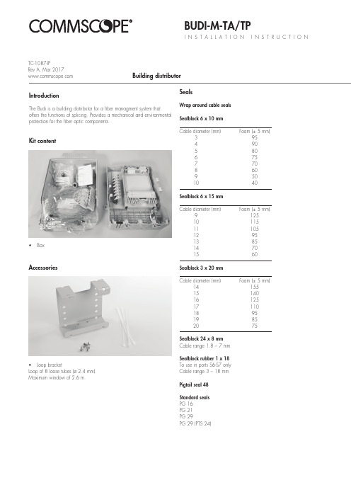
BUDI-M-TA/TPI N S T A L L A T I O N I N S T R U C T I O NBuilding distributorKit contentIntroductionThe Budi is a building distributor for a fiber managment system thatoffers the functions of splicing. Provides a mechanical and environmental protection for the fiber optic components.• BoxAccessories• Loop bracketLoop of 8 loose tubes (ø 2.4 mm).Maximum window of 2.6 m.SealsWrap around cable seals Sealblock 6 x 10 mm Cable diameter (mm) Foam (± 5 mm)3 954 905 806 757 708 609 50 10 40Sealblock 6 x 15 mm Cable diameter (mm) Foam (± 5 mm)9 125 10 115 11 105 12 95 13 85 14 70 15 60Sealblock 3 x 20 mm Cable diameter (mm) Foam (± 5 mm)14 155 15 140 16 125 17 110 18 95 19 85 20 75Sealblock 24 x 8 mm Cable range 1.8 – 7 mm Sealblock rubber 1 x 18To use in ports S6-S7 only Cable range 3 – 18 mm Pigtail seal 48Standard seals PG 16PG 21PG 29PG 29 (PTS 24)TC-1087-IPRev A, Mar 1.1 Different wrap-around ports are available (including brackets). Use two guiding pins to open the ports and to secure the bottom part tothe box. Cut out the plastic part if you want to install a cable.1.2Install the cable bracket depending the cable seal.1Preparation of the box 2.1Install the looped cable into the ports.2Looped feeder cable2.2Store the looped tubes into the loop bracket.2.3Route the loose tube towards the FAS block.3 Installation of the feeder cable3.1 Install the PG21 into the port.3.2Install the cable bracket into the box..3.3Prepare the feeder cable and insert the cable into the box.3.4 Install the cable onto the bracket, secure with hook and loop fastener and secure the aramid yarns if needed.3.5 Route the unused loose tubes towards the loop bracket for storage. Secure with te-wraps when needed.3.6 Route the loose tube towards the tube holder and strip.4Fiber routing4.1 Secure the wraparound groove plate on the UMS by putting the plate with the long protrusions in the S1 UMS-profile and sliding the plate in the S2 UMS-profile until it snaps. (Do not leave gaps between groove plates).S1S24.2 To remove push the two snapfits at S2 UMS-profile and slidethe wraparound plate towards S1 UMS-profile.4.4 Place a tray in the wraparound groove plate; do this by pushing the lip on the groove plate (lowest possible position) slightly down with the tray and move the tray lateral into the hinge-cavities of the groove plate. To snap the High Capacity Single Element tray (HCSE) in the W/a single fiber groove plate leave always one hinge facility open between Fasblock or previous tray and the HCSE-tray.4.5 To remove the tray put the fiber guiding pin between lip onwraparound groove plate and tray and move lateral towards S1.4.3 If box is not completely filled with groove plates, use pigtail clip retainer to hold the pigtails in place in the open area.4.7 Pull gently on the fibers in the tray and make sure that the fibers are well contained in the routing block and wraparound groove plate.4.6 Position the wedge carefully such that the groove is stillaccessible for the fibers and be careful not to push the wedge against fibers. To remove the wedge,use two hands to pull on both ends (near the groove plate). Route the fiber in the grooves of the wraparound groove plates to the entrance of the identified tray. Fiber must be routedin the groove below the hinge of the tray!4.8 Store the fibers temporarily on a tray (picture shows the case of a loopback).4.9 Storing dark fibers can be done in different ways.1) Organise dark fibers into the different trays, following instructions as described.2) Organise dark fibers together into the first available tray (i.e. with amax. of 24cut or 12 loops primary coated fibers in one SE-tray).5 Trays5.1 SMOUV in SC tray.5.2ANT in SE tray.5.3 ANT in SC tray.6 Patch panel TA/TP5.4 RECORDsplice in SC tray.5.5 RECORDsplice in SE tray.5.6 RECORDsplice/ANT in SC tray.5.7 Ribbon 4/8 tray.6.1 Slide the patch panel upwards up till the first locking position,not further.5.8 Ribbon 12 tray.5.9 Use a permanent marker to write on the tray.TATP6.2 Install the pigtails into the designated adaptors.TPTATATP7Connecting customers7.1 Slide the patch panel upwards until the first locking position, not futher. Connect the pigtail/patch cord into the designated adaptor.7.2 Once the top row of pigtails is installed, the pigtails can be routed towards the pigtail seal. Insert one by one into the groove.7.3Top rows can be installed in the first groove.6.3 Route the pigtails towards the tube holder, different grooves can be used to separate the bundle of pigtails if needed.TATP8Closing the box7.4 Bottom can be installed second groove.8.1Close the FAS block with the cover.8.2 Close the last tray with the cover and secure the trays with the hook and loop fastener.8.3 Closing the box.TATP© 2017 CommScope, Inc. All rights reserved. RECORDsplice, SMOUV and all trademarks identified by ® or ™ are registered trademarks or trademarks, respectively, of CommScope, Inc.This document is for planning purposes only and is not intended to modify or supplement any specifications or warranties relating toCommScope products or services.This product is covered by one or more U.S. patents or their foreign equivalents. For patents, see: /ProductPatent/ProductPatent.aspx.To find out more about CommScope® products, visit us on theweb at For technical assistance, customer service, or to report anymissing/damaged parts, visit us at:/SupportCenter。
BPS软件基础使用手册
BPS软件基础使用手册BPS软件基础使用手册IXIA系统工程师邢玮本文为BPS软件的基础使用手册,里面包含了BPS常用的几大功能配置说明,以及针对RFC3511测试所对应的L4、L7的新建、并发及L7的应用层吞吐量测试配置说明。
目录测试拓扑: (3)一、BPS界面的登录 (4)二、端口的占用 (6)三、Network Neighborhood的配置 (8)四、Application Simulator组件的测试使用 (13)A-手工建立Application Profile进行测试 (13)B-调用Application Profile模板进行测试 (34)五、Security组件的测试使用 (38)六、Session Sender的测试使用 (47)七、Bit Blaster组件的测试使用 (54)八、Routing Robot测试组件的使用 (58)九、Recreate测试组件的使用 (62)十、Stack Scrambler组件的测试使用 (70)十一、抓包 (74)十二、RFC2544的测试 (76)十三、L4的新建和并发测试 (79)十四、L7的新建和并发测试 (80)十五、L7吞吐量的测试 (84)测试拓扑:本文主要描述的是双臂测试的测试拓扑一、BPS界面的登录1. 在浏览器中输入设备的管理口地址2. 默认的用户名和密码均为admin,填完以后点击LOGIN3. 点击红框中的图标,打开BPS的主要操作界面4. 操作界面的右下方会显示当前设备的软件版本号和ATI号,通过这些可以根据使用情况判断是否需要进行升级。
当前截图的软件版本号为8.30.0,ATI号为306626二、端口的占用1. 点击右上角的红框位置,打开机框图2. 图中我们可以看到这是一台8口的1GE/10GE双速率的PerfectStorm设备3.只需要在希望的端口上点击鼠标左键进行选择,就会发现端口出现图中的样子,代表已经被选中。
TongLINKQ7.2系统安装手册_服务端安装

TongTech®TongLINK/Q7.2系统安装手册-服务端安装2009年12月TongLINK/Q V7.2系统安装手册_服务端安装北京东方通科技有限责任公司地址:北京市海淀南路32号中信国安数码港8层客户服务热线:400-650-7088Email:版权声明版权©1993-2010东方通科技版权所有。
版权保护说明未经东方通科技公司书面许可,本文档不得整体或部分地复印、复制、翻译或缩减成任何电子介质或计算机可以阅读的格式。
本文档中的信息可能不加通知进行修改。
商标©1993-2010东方通科技版权所有。
TongTech、TongLINK/Q、TongEASY、TongWeb、TongIntegrator、TongSEC、TongWorkflow、TongGTP、MBP是东方通科技的注册商标。
其他所有的公司和产品名称可能为第三方所有。
前言本手册主要介绍服务端系统安装的环境、系统安装过程、系统有关环境变量配置、系统的启动、License相关说明、系统的停止及系统日志说明等。
通过阅读此手册能快速安装和启动服务端的TongLINK/Q7.2。
1. 阅读对象本手册面向消息中间件TongLINKQ7.2产品用户以及对消息中间件感兴趣的读者。
2.手册约定本手册遵循以下约定:z手册中所有的队列控制单元简称为QCU。
z手册中所有的消息中间件TongLINK/Q7.2简称为TLQ。
z此手册适用于UNIX &Windows。
3.相关技术文档z《TongLINKQ7.2快速使用手册》主要介绍产品简介、基本概念、产品安装、发送节点和接收节点的配置、节点启动停止、程序流程、程序运行及错误号的跟踪与查找等。
z《TongLINKQ7.2系统安装手册_管理控制台安装》主要介绍TLQ管理控制台安装的环境、安装过程、有关环境变量设置、TLQ7.2控制台服务器的启动及TLQ管理控制台的登录等。
- 1、下载文档前请自行甄别文档内容的完整性,平台不提供额外的编辑、内容补充、找答案等附加服务。
- 2、"仅部分预览"的文档,不可在线预览部分如存在完整性等问题,可反馈申请退款(可完整预览的文档不适用该条件!)。
- 3、如文档侵犯您的权益,请联系客服反馈,我们会尽快为您处理(人工客服工作时间:9:00-18:30)。
普元信息技术股份有限公司
BPS Platform 7.2 产品安装指南
二〇一四年十月
I
BPS Platform 7.2 产品安装指南
目录
1. 简介................................................................................................................................................... 1 1.1. 开发版的安装内容 ............................................................................................................... 1 1.2. 企业版的安装内容 ............................................................................................................... 1 配置要求........................................................................................................................................... 3 2.1. 硬件配置............................................................................................................................... 3 2.2. 软件配置............................................................................................................................... 3 安装................................................................................................................................................... 5 3.1. 界面交互安装方式 ............................................................................................................... 5 3.1.1. 安装开发版 ............................................................................................................... 5 3.1.2. 安装企业版 ............................................................................................................. 16 3.2. 哑安装方式......................................................................................................................... 22 3.2.1. 哑安装相关配置文件 ............................................................................................. 22 3.2.2. 如何配置哑安装属性文件 ..................................................................................... 23 3.2.3. 哑安装配置文件典型示例 ..................................................................................... 26 卸载................................................................................................................................................. 30 4.1. 卸载开发版......................................................................................................................... 30 4.1.1. 卸载注意 ................................................................................................................. 30 4.1.2. 卸载步骤 ................................................................................................................. 30 4.1.3. 验证卸载 ................................................................................................................. 33 集群安装......................................................................................................................................... 34 5.1. WebLogic 集群安装 ........................................................................................................... 34 5.1.1. 搭建 weblogic 集群环境 ........................................................................................ 34 5.1.2. 通过安装包安装应用到集群 ................................................................................. 43 5.1.3. 加入 Governor 进行管理........................................................................................ 44 5.1.4. 加入 Workspace 进行管理 ..................................................................................... 46 5.1.5. 验证安装 ................................................................................................................. 46 5.1.6. Weblogic 集群安装注意事项................................................................................. 47 5.2. WebSphere 集群安装 ......................................................................................................... 49 5.2.1. 搭建 Websphere 集群环境 ..................................................................................... 49 5.2.2. 通过安装包安装应用到集群 ................................................................................. 59 5.2.3. 加入 Governor 进行管理........................................................................................ 60 5.2.4. 加入 Workspace 进行管理 ..................................................................................... 61 5.2.5. 验证安装 ................................................................................................................. 62 手工安装......................................................................................................................................... 65 6.1. 手工安装业务应用 ............................................................................................................. 65 6.1.1. 准备应用服务器环境 ............................................................................................. 65 6.1.2. 准备 EAR 应用 ........................................................................................................ 65 6.1.3. 拷贝 JDBC 驱动 jar ................................................................................................ 65 6.1.4. 部署数据源、JMS 等应用绑定资源..................................................................... 66 6.1.5. 部署应用 ................................................................................................................. 68 6.1.6. 配置外置目录和启动参数 ..................................................................................... 69
