catia实体练习
CATIA实体设计实例6-2

第二節風扇第一項風扇之前後蓋第二項風扇之心軸與葉片第三項風扇之組立第一項風扇之前後蓋一、擠伸成形底蓋二、擠製成形本體三、擠伸切割底蓋圓槽四、擠製成形底蓋徑向肋五、環狀陣列及圓角六、編修草圖七、圓角特徵八、擠伸成形中心軸一、擠伸成形底蓋1. 繪製草圖在作業系統中按下(Catia)圖示,選擇(零件設計)Part Design模組,並在模型樹中選擇xy面,作為繪製草圖之工作平面,接著選擇(草圖)圖示進入草圖模式。
在草圖模式中選擇(矩形)及(草圖圓角)圖示,繪製出如下圖左之草圖。
最後選擇(離開)圖示,離開草圖模式回到零件設計之實體模組,完成之草圖輪廓如下圖右所示。
2. 完成擠伸成形實體在工具箱中選擇(擠伸成形)圖示,系統即顯示如下圖左之對話框,提供擠伸成形之參數設定。
對話框中第一欄接受預設值之Dimension指定尺寸,第二欄中鍵入4如圖所示,指定擠伸之距離為4mm,按下OK即完成設定。
完成參數設定之後,系統顯示如下圖右之擠伸成形實體。
按住滑鼠中鍵可平移圖元,按住中鍵加左鍵可旋轉圖元。
若要縮放模型顯示之大小,則按住中鍵後輕點左鍵,將滑鼠上下移動即可縮放模型。
二、擠製成形本體1. 指定工作平面在工具箱中選擇(選擇)圖示,並以滑鼠左鍵點選擠伸成形實體表面作為草圖平面。
點選之後系統顯示該平面之邊緣線如下圖左,平面塗彩後顯示如下圖右所示。
2. 繪製圓形草圖在工具箱中選擇(草圖)圖示進入草圖模式,再選擇(圓)圖示並繪製兩圓,接著點選(尺寸限制)標註草圖上所需的尺寸,之後再點選(選擇)圖示進行尺寸的編修,完成之草圖如下圖左所示。
按住鍵盤Ctrl鍵並分別點選兩圓如下圖中,接著點選鉛直座標軸V軸作為草圖鏡射之基準軸,如下圖右所示。
3. 草圖水平鏡射在工具箱中選擇(草圖鏡射)圖示,系統即產生鏡射圖元如下圖左。
繼續按住鍵盤Ctrl鍵並分別點選四圓如下圖中,接著點選水平座標軸H軸作為草圖鏡射之基準軸,如下圖右所示。
4. 草圖垂直鏡射同樣在工具箱中選擇(草圖鏡射)圖示,系統即產生鏡射圖元如下圖左。
CATIA实体模型练习 Tee Fitting
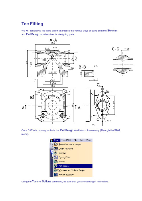
Tee FittingWe will design this tee fitting screw to practice the various ways of using both the Sketcher and Part Design workbenches for designing parts.Once CATIA is running, activate the Part Design Workbench if necessary (Through the Start menu).Using the Tools -> Options command, be sure that you are working in millimeters.Using the Tools -> Options command, be sure that the sketcher grid has the following parameters:Creating PadsIn this section, we are going to build four simple pads corresponding to a quarter of the Tee Fitting.We are going to build this pad:Then this one:Then this one:And finally this one:1. Activate the Sketcher icon , then select the XY plane.2. Activate the Rectangle icon and using the grid, create the following rectangle:3. Leave the Sketcher by selecting the Exit icon .4. Now, activate the Pad icon , then create a pad with the following parameters:5. Activate the Sketcher icon , then select the following face:6. Using the grid, build the following lines:7. Leave the Sketcher by selecting the Exit icon .8. Now, activate the Pad icon , then create a pad with the following parameters:9. Activate the Sketcher icon , then select the following face:10. Using the grid, build the following lines:11. Leave the Sketcher by selecting the Exit icon .12. Now, activate the Pad icon , then create a pad with the following parameters:13. Activate the Sketcher icon , then select the following face:14. Using the grid, build the following profile:15. Add the following corners:16. Using the grid, create the following strait line:17. Activate the Trim icon and trim the corners with the strait line in order to get:18. Delete the two following lines:19. Leave the Sketcher by selecting the Exit icon .20. Now, activate the Pad icon , then create a pad with the following parameters:You get :Draft Angles and FilletsIn this section, we are going to build the following draft angles (green) and fillets (red):1. Activate the Draft Angle icon and create a draft angle with the followingparameters:2. Activate the Draft Angle icon and create a draft angle with the followingparameters:3. Activate the Draft Angle icon and create a draft angle with the followingparameters:4. Activate the Edge Fillet icon and create a fillet on the edge with the followingparameters:5. Activate the Edge Fillet icon and create a fillet on the three edges with thefollowing parameters:6. Activate the Edge Fillet icon and create a fillet on the three edges with thefollowing parameters:You get :Holes CreationIn this section, we are going to build the two following holes:1. Activate the Hole icon then select the following face:2. Enter the following parameters in the dialog box (Extension tab):3. Enter the following parameters in the dialog box (Type tab):4. Select the Extension tab then activate the Positioning Sketch iconfrom the dialog box.5. Using the Ctrl key, select the edge and the point as shown below.6. Activate the Constraints Defined in dialog Box icon7. Select the Concentricity option from the dialog box then select OK.8. Leave the Sketcher by selecting the Exit icon .You get:9. Activate the Hole icon then select the following face:10. Enter the following parameters in the dialog box (Extension tab):11. Enter the following parameters in the dialog box (Type tab):12. Select the Extension tab then activate the Positioning Sketch iconfrom the dialog box.13. Using the Ctrl key, select the edge and the point as shown below.14. Activate the Constraints Defined in dialog Box icon15. Select the Concentricity option from the dialog box then select OK.16. Leave the Sketcher by selecting the Exit icon .You get:MirroringIn this section we are going to mirror the part in order to get:1. Activate the Mirror icon , then select the following face:2. Select OK in the dialog box.You get:3. Activate the Mirror icon , then select the following face:4. Select OK in the dialog box.You get:Mold Core: Shaft CreationIn this section, we are going to build the inside of the tee fitting. To do it, we are going to create a body in which we are going to build a solid corresponding to the material to be removed from the main part then we will physically remove this body to the part body to get the final result.1. First of all, we need to insert a new Body. To do it, select the Insert + Body function. Theinserted body becomes automatically the working object.The tree becomes:2. To better see the core creation, we are going to put the part body in the No Show. ActivateNow, we are going to build the following shaft:3. Activate the Sketcher icon , then select the ZX plane.4. Using the grid, create and constrain the following profile:5. Because we are building a shaft, we need to create an axis. So, activate the Axis icon, then using the grid, cearthe the following axis:6. Leave the Sketcher by selecting the Exit icon .7. Now, activate the Shaft icon then select the previously created sketch.8. Enter the following parameters in the dialog box, then select OK.You get:Mold Core: FilletingIn this section, we are going to create the following fillets:1. Activate the Edge Fillet icon and create a fillet on the two edges with the followingparameters:You get:Mold Core: Shaft CreationIn this section we are going to build the following shaft:1. Activate the Sketcher icon , then select the ZX plane.2. Using the grid, create the following profile:3. Because we are building a shaft, we need to create an axis. So, activate the Axis icon, then using the grid, cearthe the following axis:4. Leave the Sketcher by selecting the Exit icon .5. Now, activate the Shaft icon then select the previously created sketch.6. Enter the following parameters in the dialog box, then select OK.You get:Mold Core: FilletingIn this section, we are going to create the following fillets:1. Activate the Edge Fillet icon and create a fillet on the three edges with thefollowing parameters:You get:Removing BodyIn this section, we are going to remove the core from the main part.1. We are going to put the part body in the Show. Activate the Hide/Show icon thenselect the PartBody from the tree.2. Place the cursor on the body containing the core (in the tree), then select the Body.2object + Remove function from the contextual menu (MB3).You get:You can save the Tee Fitting.。
catia练习题目

catia练习题目CATIA是一款由法国达索公司(Dassault Systèmes)开发的三维计算机辅助设计(CAD)软件。
它被广泛应用于工程设计和制造领域,具有强大的建模和仿真功能。
本文将为您提供一些CATIA练习题目,帮助您熟悉和掌握CATIA软件的使用。
1. 创建基本几何图形使用CATIA绘图工具创建以下几何图形:- 一个正方形- 一个圆形- 一个矩形- 一个三角形2. 创建三维实体使用CATIA的建模功能创建以下三维实体:- 一个立方体- 一个圆柱体- 一个球体- 一个锥体3. 进行零件组装在CATIA中创建两个简单的零件,然后将它们组装在一起。
确保它们正确对齐并能够实现运动。
4. 进行零件绘图在CATIA中选择一个零件,然后创建一个零件绘图。
确保绘图符合工程标准,并包含尺寸和注解。
5. 进行动态仿真在CATIA中创建一个简单的机械装配,并应用动态仿真功能。
通过给装配施加合适的运动,观察各零件之间的相互作用和运动关系。
6. 进行渲染效果展示在CATIA中为一个设计好的实体模型添加材质和纹理效果,然后渲染出一个逼真的图像。
尽量使渲染图像具有高质量和真实感。
7. 进行工程数据分析在CATIA中导入一个复杂的实体模型,然后使用分析工具进行工程数据分析。
例如,应力分析、流体仿真等。
8. 进行装配间干涉检查在CATIA中进行装配间干涉检查,确保各零件之间没有干涉或碰撞的问题。
如有干涉,及时进行调整和修正。
9. 创建自定义工具库在CATIA中创建一个自定义的工具库,将常用的功能和操作进行整理和组织,提高工作效率。
10. 进行项目管理和团队协作在CATIA中使用项目管理功能,进行项目文件和数据的管理,并与团队成员进行协作和共享。
通过完成以上练习题目,您可以大大提升您对CATIA软件的熟练程度和应用能力。
CATIA作为一款功能强大的CAD软件,广泛应用于制造、航空航天、汽车等行业。
掌握CATIA的使用将为您在工程设计和制造领域带来更大的发展机遇。
2024版CATIAV教程实体零件设计

02
创建装配体文件
03 在CATIA中新建一个装配体文件,
作为后续操作的容器。
导入零部件
将需要参与装配的零部件导入 到装配体文件中。
04
定义零部件关系
05 通过添加约束、连接等方式定
义零部件之间的相对位置关系。
验证装配设计
06 检查装配体是否满足设计要求,
进行必要的调整和优化。
2024/1/26
20
进行工程图的输出打印。
2024/1/26
02 03
图纸管理
CATIA V5提供了图纸管理功能,可以对工程图进行版本控制、归档等 操作。选择“工具”->“选项”->“常规”->“文档管理”,可以设 置图纸管理的相关参数。
导出其他格式
如果需要将工程图导出为其他格式(如DWG、DXF等),可以选择 “文件”->“另存为”,在弹出的对话框中选择需要的格式进行保存。
2024/1/26
在二维平面上绘制的图 形,用于定义特征的截
面形状。
5
限制草图元素之间或元 素与坐标系之间的相对
位置和关系。
设计环境设置与界面介绍
设计环境设置
包括单位制、坐标系、工作平面、图层等设置, 以确保设计环境的准确性和一致性。
界面介绍
CATIAV软件界面主要包括菜单栏、工具栏、特 征树、属性窗口等部分,各部分功能如下
29
THANK YOU
2024/1/26
30
2024/1/26
25
06
工程图生成与标注
2024/1/26
26
工程图生成方法及步骤
新建工程图
在CATIA V5中,选择“开始”>“机械设计”->“工程制图”,进 入工程制图界面,创建新的工程图。
CATIA实体模型练习-Lever
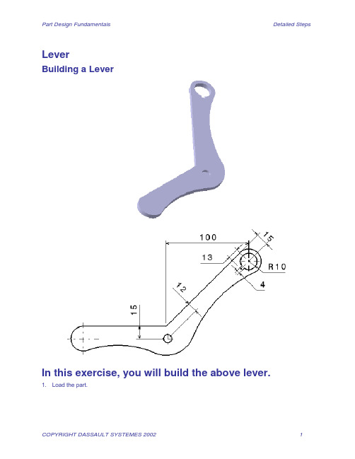
LeverBuilding a LeverIn this exercise, you will build the above lever.1. Load the part.2. Make a pad with the sketcher in the positive OZ direction with an height of 5.3. Enter the sketcher by selecting the bottom face of the previously created pad.4. Generate the following rough profile with the icon. Do it in one shot.5. Delete all the constraints6. Add the following radial constraint7. Add the following distance constraints.8. Add the following distance constraint.9. Add the following distance constraint.10. Add the following concentricity constraint between the arc of the sketcher and the circular edge of thepad.11. Add the following parallelism constraint between the two following edges.12. Add the following perpendicularity constraint between the two following edges.13. Exit the sketcher .14. Make a pocket with the following options.15. You are going to make a hole in the part, before activating the hole icon, select the two following edgesusing the Ctrl key (the left one in first).16. Activate the hole icon .Select the top face of the part.17. Modify the following pocket parameters and change them to 12 and 15 respectively.18. Enter the following parameters in the dialog box then validate.19. You have the following result. Save it.Finishing the LeverIn this exercise, you will finish the following lever.1. Load a part called CATPDGEXSketch2.CATPart.2. You are going to duplicate the blind hole. To do so, select the hole to be duplicated, then activate theRectangular Pattern icon.3. Select the Reference direction field (first direction) in the dialog box then select the following edge.4. If necessary, reverse the reference direction by activating the reverse button from the dialog box, thenenter the following parameters.5. Select the Second direction tab from the dialog box then activate the Reference element field.6. Select the following edge for the second direction.7. If necessary, reverse the reference direction by activating the reverse button from the dialog box, thenenter the following parameters.8. In order to remove the non necessary instances, select the center of the instances you do not wantanymore, then validate.9. Now, you are going to add a fillet of 40mm radius on the part. So, select the following edge thenactivate the fillet icon.10. Enter a radius of 40 in the dialog box, then validate.11. Now, you are going to add a draft angle on the outside of the part. So, select the following face.12. Activate the Draft icon.13. Select the Neutral element selection field in the dialog box.14. Select the bottom face of the part for the neutral element.15. If necessary, reverse the pulling direction in order to have it in the OZ positive direction.16. Enter an angle of 5 degree in the dialog box then validate. The draft angle is created.17. Now, you are going to make a draft angle on the cylindrical faces of each holes. So, using the Ctrl key,select the six cylindrical faces.18. Activate the Draft icon.19. Select the Neutral element selection field in the dialog box.20. Select the bottom face of one of the hole for the neutral element.21. If necessary, reverse the pulling direction in order to have it in the OZ positive direction.22. Enter an angle of 5 degree in the dialog box then validate. The draft angle is created.23. Now, you are going to fillet edges. So, using the Ctrl key, select the following edges.24. Activate the Edge fillet icon.25. Enter a radius of 1 in the dialog box then validate. You have the following result.26. To finish the part, you are going make a mirror of the part using the bottom face of the part for themirroring element. So activate the Mirror icon.27. Select the bottom face of the part then validate.28. You have the following result. Save it.。
CATIA草图及实体应用(新人学习)

选取元素
2
旋转中心
3
相对 0 度
4
旋转角度
4
5
完成
操作 工具条
缩放
缩放比例
选取元素
缩放原点
完成
操作 工具条
縮放
不延伸
切线延伸
点延伸
双边偏移
若要使用草图工具组有下列事项要注意︰ 1.要先输入复制体的数量才输入偏移距离 2.偏移距离的正值是指目前滑鼠指标所在的那一边
操作 工具条
立体元素投影
等角图
线、线 同一 2个
圆弧、圆弧 同一 3个
相切 1个
同心的 2个
平行 1个
垂直 1个
水平、铅直 1个
固定、对称 全部
等距点 1个
从 2D (ex : AutoCad ) 转换成 3D 的草图时,虽然都是 2D 的轮廓,但是观念有些不同︰ 在以往 2D 的观念中 [几何约束] 通常会很习惯在画图时可能就以锁点的方式定义完成 在 CATIA 的草图中则必需要有 [几何约束的符号] 出現才行 故在草图工具组中的 [几何约束] 及 [尺寸约束] 的图示要开启,否则不会自动建立以侦测到的约束,这样的话必需要以手动加入 约束会增加作图的困难
向内增加壁 厚值
向外增加 壁厚值
欲移走的表 面
特殊壁厚的 表面
断面 工具条 – 预先定义断面
矩形
2
任意方向矩形
1
3
1
2
平行四边形
3 1
2
多边断面
1
2
3
曲线形多边断面
4
2 3
1
键孔断面
1 4
3 2
六边形
1 2
断面 工具条 – 圆
2024版CATIAV5教程实体零件设计学习教案

干涉检查与调整策略
干涉检查
利用CATIA的干涉检查功能,检测装 配体中各零件之间是否存在干涉现象。
调整策略
对于发现的干涉问题,可以通过修改零 件尺寸、调整零件位置或添加间隙等方 法进行解决。
爆炸视图创建方法
自动爆炸
01
利用CATIA的自动爆炸功能,根据装配约束自动生成爆炸视图。
手动爆炸
02
手动设置各零件的移动方向和距离,创建符合实际需求的爆炸
文件版本控制与备份
阐述文件版本控制的重要性,以及如何进行 文件备份和恢复。
打开文件与导入导出
介绍如何打开已有的设计文件,以及导入导 出不同格式的数据文件。
工作环境与参数设置
提供工作环境定制与参数设置的建议,以提 高设计效率。
基本操作技巧与快捷键
01
02
03
04
选择与取消选择
介绍如何选择单个或多个对象, 以及取消选择的方法。
曲面创建与编辑方法
曲面生成
利用拉伸、旋转、扫描等曲面生成方法创建基础曲面。
曲面编辑
应用曲面修剪、延伸、倒角等工具对曲面进行编辑。
曲面拼接与缝合
将多个曲面拼接在一起,形成完整的零件表面;使用 缝合操作将曲面转换为实体。
复杂结构零件建模策略
分解复杂结构 将复杂零件分解为若干简单的子零件,
分别进行建模。
镜像和阵列图形元素
草图修复和检查
使用镜像和阵列工具可以快速复制并排列多 个相同的图形元素,提高设计效率。
在草图绘制完成后,可以使用草图修复和检 查工具检查草图的完整性和正确性,并进行 必要的修复和调整。
04
实体零件建模方法
基于草图的特征建模
创建2D草图
CATIA参数化(实体)数据设计培训教程

培训目标
使学员熟练掌握CATIA参数化 设计技能,能够独立完成复杂
产品的设计工作。
PART 02
CATIA参数化设计基础
REPORTING
参数化设计概念
参数化设计的定义
参数化设计是一种基于参数变量 进行建模的设计方法,通过调整 参数值来改变模型形状和尺寸。
参数化设计的优势
能够快速生成多种设计方案,提 高设计效率;便于修改和优化设 计,减少重复工作;支持设计重 用和标准化。
PART 06
工程图与标注技术
REPORTING
工程图基础
1 2
工程图概述
工程图是产品设计的重要输出,用于表达产品的 形状、尺寸、材料和制造要求等信息。
工程图类型
包括零件图、装配图、工艺流程图等,不同类型 的工程图有不同的表达方式和要求。
3
工程图规范
工程图的绘制需要遵循一定的规范和标准,如国 家标准、行业标准等,以确保工程图的准确性和 通用性。
PART 07
总结与展望
REPORTING
培训总结
掌握了CATIA参数化设计的基本原理和方法
通过本次培训,学员们深入理解了CATIA参数化设计的核心思想,熟悉了基于特征、参 数和规则的设计方法。
学会了创建和管理参数化模型
学员们掌握了在CATIA中创建参数化模型的关键技术,包括草图绘制、特征创建、参数 设置和模型管理等。
CATIA工程图工具
CATIA工程图界面介绍
CATIA工程图模块的用户界面包括菜单栏、工具栏、绘图区等部 分,熟悉这些界面元素是进行工程图设计的基础。
工程图创建与编辑
通过CATIA的工程图工具,可以创建新的工程图文件,并在其中绘 制图形、添加文本和标注等。
CATIA学习资料

保留所選部份元素
打斷所選部份元素
操作 工具列
對稱
2
1
限制︰ 於[步驟1] 選取元素僅能 一次選取,即複選物件 僅能使用一次框選的方 式.接著就必需選取對稱 軸了 [轉換] 工具列中的所有 命令都有這個限制 若要複選元素都要使用 下面的操作順序
選取對稱元素
選取對稱軸
2
3
1
複選對稱元素
選取對稱軸
完成
操作 工具列
指令及工具列簡介
圓倒截轉立 角角斷換體 幾 何
作用中模組的主要工具,全部在 [ 插入 功能表 ] 內
建立拘束條件 自動產生拘束條件 驅動拘束條件 斷面 預先定義斷面 圓 雲形線 圓錐 線 軸 點
如何判斷現在位於那一個草圖
當零件中有 2 個以上未使用的 草圖時,假設有 草圖.1、草圖.2、草圖.3
旋轉
4
2 3
旋轉角度
1
5
選取元素
旋轉中心
相對 0 度
4
完成
操作 工具列
縮放
縮放比例
選取元素
縮放原點
完成
操作 工具列
縮放
不延伸
切線延伸
點延伸
雙邊偏移
若要使用草圖工具組有下列事項要注意︰ 1.要先輸入複製體的數量才輸入偏移距離 2.偏移距離的正值是指目前滑鼠指標所在的那一邊
操作 工具列
立體元素投影
左圖中的尺寸關係式如下 35mm = 70mm /2 52.5mm = 35mm *1.5 140mm = 70mm *2 右圖中 將 70mm 設變為 60mm 相關尺寸即自動更新
草圖.1 依附在 平面.1 上 在左圖 平面.1 現旋轉的 角度為 30deg 右圖已將 平面.1 設變角 度為 60 deg
CATIA参数化(实体)数据设计培训教程
-B 加强筋和翻边搭接结构 -C 主体料厚(A面)和翻边搭接结构 -D 布尔运算(–A、-B和-C组合体) -E 圆角修饰和局部优化
9
CATIA参数化(实体)数据设计
➢ 以布尔运算作为主要的数据组织形式;
编辑和修改时直接追踪到带参的原始文档, 改完后更新即可,不更改则不需要更新。
点选链接的结果,通过鼠标右键,可 以追踪到带有参数的原始文档
每一步都是由 简单的方形和
圆形组成
7
CATIA参数化(实体)数据设计
➢ 建模过程模块化(即分解因式):零件设计横向分块,把复杂的零 件分解为多个相对独立的局部结构,每个独立结构建立Body,要求 驱动其关键点能够驱动此独立结构的空间位置及角度任意调整;
每一个Body里 是一种相同的
结构
8
CATIA参数化(实体)数据设计
14
实体参数建模: ➢ 塑料零件:
课后作业
➢ 钣金零件:
15
16
3
CATIA实体
➢单一特征操作,实体优于片体:
左图中绿色面增厚10mm,黄色面 减少-15mm,蓝色面增加20mm。 (实体和片体进行操作)
实体操作只需一个加厚 (减薄)命令,若干面 都能同时完成
片体操作需 要相当多的 命令和步骤
4
CATIA实体
➢数据修改,实体优于片体:
将下图中红色圆角面R5更改为R8,实体比较容易,片体操作相当于重做。
➢ 内外饰数据设计可以提前启动:
当Benchmark车型样件拆解后,我们就可以照着样件,将相同类型的 局部结构,通过驱动参数布置到整车大致的位置(我们也可以把同 一平台前期已经开发的车型相关数据作为参考,开始数据设计工作 ),当新开发车型的白车身数据及相关数据的完成逐步去完善,逐 步调整到整车位置(M0=>M1=>M2,就是逐步完善的过程)。所以内 外饰数据创建可以与Class-A及白车身同步(甚至提前)工作。
catia草图练习题

catia草图练习题在Catia软件中,草图练习题对于提高绘图技巧和熟练使用工具非常重要。
下面我将为您提供一些CATIA草图练习题的示例,并附上详细的步骤和解答。
1. 练习题一:绘制一个矩形步骤:1. 打开Catia软件,选择新建草图,并选择一个平面作为绘图平面。
2. 使用绘图工具中的矩形工具,点击草图平面上的一个点,然后拖动鼠标,绘制出一个矩形。
3. 按照需要调整矩形的尺寸和位置,可以使用尺寸工具控制矩形的大小。
4. 点击完成草图,生成矩形。
2. 练习题二:绘制一个圆形步骤:1. 新建一个草图并选择绘图平面。
2. 使用绘图工具中的圆工具,在草图平面上选择一个起始点作为圆心,然后拖动鼠标绘制出一个圆形。
3. 按照需要调整圆形的半径,可以使用尺寸工具控制圆形的大小。
4. 点击完成草图,生成圆形。
3. 练习题三:绘制一个椭圆步骤:1. 新建一个草图并选择绘图平面。
2. 使用绘图工具中的椭圆工具,在草图平面上选择一个起始点作为椭圆的一个焦点,然后拖动鼠标绘制出一个椭圆。
3. 按照需要调整椭圆的长轴和短轴,可以使用尺寸工具控制椭圆的大小。
4. 点击完成草图,生成椭圆。
4. 练习题四:绘制一个多边形步骤:1. 新建一个草图并选择绘图平面。
2. 使用绘图工具中的线工具,点击草图平面上的每个顶点,绘制出一个多边形的边界。
3. 按照需要调整多边形的形状和大小,可以使用尺寸工具控制多边形的尺寸。
4. 点击完成草图,生成多边形。
通过以上练习题,您可以熟悉使用Catia软件的草图绘制功能,并进一步提高您的绘图技巧。
请注意,这只是一些基础的练习题,您可以根据自己的需要和发展,挑战更复杂的草图练习题。
希望这些练习题对您有所帮助。
如果您还有其他问题或需求,请随时告诉我。
CATIA实体曲面混合设计练习题

Load : SMBase_step3.CATPart
Copyright DASSAULT SYSTEMES 2002
15
Do It Yourself : step 5
Select the imported_surface in the tree and put it in Show mode :
5 min.
Sew the just created surface on the solid.
Copyright DASSAULT SYSTEMES 2002
12
Do It Yourself
In the CATIA Part Design workbench, sew the previously created split surface with the solid.
CATIA技术论坛:
CATIA Training
Exercises
CATIA技术论坛:
Generative Shape Design
Version 5 Release 8 January 2002 EDU-CAT-E-GSD-FX-V5R8
Copyright DASSAULT SYSTEMES 2002
CATIA技术论坛:
Create a line closing the first profile :
Copyright DASSAULT SYSTEMES 2002
10
Do It Yourself (2/3)
CATIA技术论坛:
Create a fill surface between the line and the first sketch.
1
Exercise
2024年catia培训实体教程-(多应用版)
catia培训实体教程-(多应用版)CATIA培训实体教程:全面解析三维设计软件的使用技巧与实战应用引言:CATIA是一款广泛应用于航空航天、汽车、机械制造等行业的三维设计软件。
本教程旨在为初学者提供全面、系统的CATIA培训,帮助学员掌握CATIA的基本操作、功能模块及实战应用。
通过本教程的学习,学员将能够熟练使用CATIA进行三维建模、装配、工程图绘制等设计工作。
第一章:CATIA软件概述1.1CATIA的历史与发展1.2CATIA的功能模块介绍1.3CATIA的应用领域第二章:CATIA软件安装与启动2.1CATIA软件的安装要求2.2CATIA软件的安装步骤2.3CATIA软件的启动与退出第三章:CATIA基本操作与界面介绍3.1CATIA的用户界面布局3.2CATIA的基本操作与快捷键3.3CATIA的视图控制与对象选择第四章:CATIA草图绘制4.1草图绘制的概念与重要性4.2草图绘制的工具与命令4.3草图绘制的约束与标注4.4草图绘制的实战案例第五章:CATIA三维建模5.1三维建模的基本概念5.2三维建模的工具与命令5.3三维建模的约束与标注5.4三维建模的实战案例第六章:CATIA装配设计6.1装配设计的概念与重要性6.2装配设计的工具与命令6.3装配设计的约束与标注6.4装配设计的实战案例第七章:CATIA工程图绘制7.1工程图绘制的概念与重要性7.2工程图绘制的工具与命令7.3工程图绘制的标注与注释7.4工程图绘制的实战案例第八章:CATIA综合应用案例8.1案例一:汽车零部件设计8.2案例二:航空航天组件设计8.3案例三:机械产品设计通过本教程的学习,学员将能够全面掌握CATIA软件的基本操作、功能模块及实战应用。
然而,CATIA是一款功能强大的三维设计软件,其学习曲线相对较陡峭。
因此,学员在学习过程中应注重实践操作,多进行案例练习,不断提高自己的设计能力。
同时,学员还可以参加相关的CATIA培训课程,与专业人士交流学习,进一步提升自己的技能水平。
Catia实体设计

创建盒体特征
按照以下步骤创建简单的盒体实体特征 Step 1:单击 按钮;
Step 2:选择要移除的平面; Step 3:定义盒体厚度,并点击确定。
定义厚度并确定
Confidential Information
实体设计(2 days) 实体设计
认识实体设计操作界面 创建基于草图的特征 创建盒体特征
本 节 课 程 内 容
Confidential Information
实体设计(2 days) 实体设计
认识实体设计操作界面
创建基于草图的特征 创建盒体特征 变换实体特征 特征管理及建模思路
几何体(body) 如何划分几何体 几何图形集( Geometrical Sets) 布尔运算
练习 (1)隧洞设计 (2)进水塔实体造型设计 (3)多截面实体设计命令 (4)主次几何体的运用 下一节培训内容及课后练习
Confidential Information
创建基于草图的特征
五、多截面实体
按照以下步骤创建简单的多截面实体特征 Step 1:单击 按钮;
Step 2:在工作窗口依次选择截面轮廓,选择每一个轮廓时 应注意闭合点的位置和方向; Step 3:点击预览并在对话框中定义其它必要的条件; Step 4:点击“确定”完成多截面实体征的创建,多截面实 体特征将被自动添加到特征树中,相对应的草图和其他元素 被移动到多截面实体特征下面。
Confidential Information
变换实体特征
四、矩形阵列实体特征
阵列实体特征是指以制定的尺寸和特定的形式一次性创建多个特征,可以加速特征 创建过程,此处仅以矩形阵列实体特征为例,圆形阵列、用户阵列雷同。 Step 1:单击 按钮; Step 2:在“矩形图样定义”对话框中定义参数。(此处第一方向和 第二方向均定义2个实例。)
CATIA实体设计实例2-2
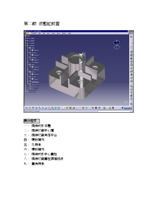
第二節液壓缸前蓋操作程序:一、擠伸成形本體二、擠伸切割中心槽三、擠伸切割角落平台四、環狀陣列五、孔特徵六、環狀陣列七、擠伸成形中心圓柱八、擠伸切割圓柱頂端凹緣九、圓角特徵一、擠伸成形本體1. 繪製草圖在作業系統中按下(Catia)圖示,選擇Part Design (零件設計)模組,並在模型樹中選擇xy面,作為繪製草圖之工作平面,接著選擇(草圖)圖示進入草圖模式。
在草圖模式中選擇(矩形)及(草圖圓角)圖示,繪製出如下圖左之草圖並以(尺寸標註)圖示標註其尺寸。
最後選擇(離開)圖示,離開草圖模式回到零件設計之實體模組,完成之草圖輪廓如下圖右所示。
2. 擠伸成形在工具箱中選擇(擠伸成形)圖示,系統即顯示如下圖之對話框,提供擠伸成形之參數設定。
對話框中第一欄接受預設值之Dimension指定尺寸,第二欄中鍵入50如圖中所示,指定擠伸之距離為50mm,按下OK即完成設定。
3. 完成擠伸成形實體完成參數設定之後,系統顯示如下圖之擠伸成形實體。
按住滑鼠中鍵可平移圖元,按住中鍵加左鍵可旋轉圖元。
若要縮放模型顯示之大小,則按住中鍵後輕點左鍵,將滑鼠上下移動即可縮放模型。
二、擠伸切割中心槽1. 指定工作平面在工具箱中選擇(選擇)圖示,並以滑鼠左鍵點選擠伸成形實體表面作為草圖平面。
點選之後系統顯示該平面之邊緣線如下圖左,平面塗彩後顯示如下圖右所示。
2. 繪製草圖在工具箱中選擇(草圖)圖示進入草圖模式如下圖左,接著選擇(連續線)圖示,並繪製如下圖右之草圖輪廓。
當按下(抓取網格點)圖示時,該圖示變更為橘紅色顯示,此時可以滑鼠左鍵沿網格點抓取特定長度之輪廓,因此本圖示橘紅色顯示時又稱為鎖點模式。
3. 擠伸切割完成草圖繪製之後,在工具箱中選擇(離開)圖示,離開草圖模式回到零件設計之實體模組。
再選擇(擠伸切割)圖示,系統即顯示如下圖右之對話框,提供擠伸切割之參數設定。
對話框中第一欄接受預設值之Dimension指定尺寸,第二欄中鍵入30mm如圖中所示。
CATIA实体模型练习——Angle Bracket
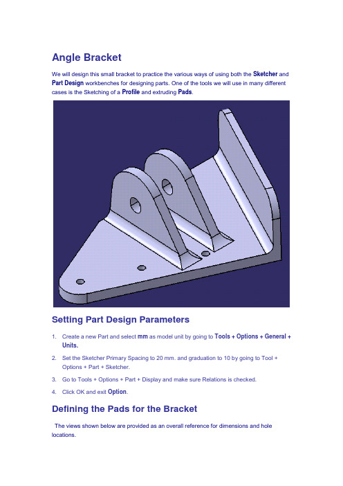
Angle BracketWe will design this small bracket to practice the various ways of using both the Sketcher and Part Design workbenches for designing parts. One of the tools we will use in many different cases is the Sketching of a Profile and extruding Pads.Setting Part Design Parameters1. Create a new Part and select mm as model unit by going to Tools + Options + General +Units.2. Set the Sketcher Primary Spacing to 20 mm. and graduation to 10 by going to Tool +Options + Part + Sketcher.3. Go to Tools + Options + Part + Display and make sure Relations is checked.4. Click OK and exit Option.Defining the Pads for the BracketThe views shown below are provided as an overall reference for dimensions and hole locations.1. We will first define all the sketches / pads for the Bracket. We will start with the 3 mm. thinflange.2. Select the XY plane and enter the Sketcher. Draw the first sketch using Rectangle iconand dimension as follows:3. Exit Sketcher and create a Pad with height of 26 mm above sketch.We will now create the base pad of the part:4. Reselect the XY plane and go back into Sketcher. Use Profile to sketch thenconstrain the new contour to the boundaries of the existing Pad and apply theappropriate dimensions .5. Extrude this second Pad to a height of 4 mm.Defining the Pilot Holes and the Angular Pads for the BracketNext we would like to create the two angle flanges (clevis).To create this geometry, we will require an angular Plane at 24 Degrees with respect to the YZ plane in order to sketch our profile. Since our drawing calls out the position of these flanges from the position of the pilot hole located between the flanges, we will make our plane pass through the center of this hole so that we will readily have available the values of the extrusion limits.Since our 24 Degrees Plane will pass through the center of one of the pilot holes, we will need to locate this hole in the model. Consequently, we might as well create all the pilot holes first.1. Position the first hole by first selecting the reference edges, the Hole feature icon,and finally the top of the pad into which the holes are drilled. Put in the appropriate locating dimensions and the hole diameter per the part drawing at the beginning of this exercise.Use the Up to Next option.2. Position the second hole by first selecting the reference edges, the Hole feature icon,and finally the top of the pad into which the holes are drilled. Put in the appropriate locating dimensions and the hole diameter per the part drawing at the beginning of this exercise. Use the Up to Next option.3. Create the third hole by first selecting the rounded edge the Hole feature icon , andfinally the top of the pad into which the holes are drilled. Put the appropriate hole diameter(3), the hole is automatically centered on the rounded edge. Use the Up to Next option.We will now create the 24 Degrees plane through the center of one of the pilot holes. To do it, display the Plane icon by selecting the View + Toolbars + Reference Elements (Extended)4. Select the Plane icon and create the required plane using the Plane Type of“Angle/Normal to Plane”. Select the vertical pad wall as reference and the pilot hole asthe rotation axis for the plane. Put in –24 Degrees to get the desired orientation.5. To redefine the PartBody as the In Work Object place the cursor on the PartBody in thetree then select the Define In Work Object command from the contextual menu.6. Select the plane you just created and go into the Sketcher to create the following profile.As before, constrain the profile to the existing geometry and apply the appropriatedimensions.7. Create a pad from this sketch with a thickness of 4 mm. (use the 2 limits option).We will now create the other Clevis by using the Rectangular Pattern tool (you can find this tool under Insert/Transformation Features)8. Click on the Rectangular Pattern Icon , select the existing Clevis, select the red edgebelow for the reference direction, and put in 2 instances spaced at 16 mm.Defining the Clevis Through Hole and Fillets1. In order to define a concentric hole, select the outside R 13 edge of the left Clevis, theHole tool , then the outside face of this Clevis. Put in 6 mm for the diameter and use the “Up to Last” option.Use Edge Fillet to create all the fillets.(You can multi-select edges by keeping the CTRL key pressed during selection.)2. Create the R3 fillets (5 edges).3. Create the R6 fillets (2 edges).4. Finally, create the R8 fillets (2 fillets).。
CATIA-实体练习

tDesign练习(step by step)
希望藉由Solid练习加强常用指令的熟悉度
Step15完成图希望练习后结果如下…如果不是…..请再复习加深印象!!谢谢,若有错误之处,请不吝指教!!
Step7制作新的Sketch并标注尺寸及相对位置。(R1=7,R2=16,X=31,Y=33)
Step8长肉厚PAD,对称长出20mm(总长:40mm)
Step9制作新的Sketch(草图),绘制同心的长圆图。
Step10执行除料(Pocket),选择除料方式到下一的面(Up to Next)。
Step11作圆形的数组复制,选择刚除料的特征,在选参考像素,于数组窗口中,选择复制条件,及复制数量。参数如下图所示
Step12制作新的Sketch(草图),选择垂直的参考平面,再绘制如下图的Sketch,并标注尺寸及相关位置。批注:详细尺寸资料如下,制作这个Sketch时请记得将要参考的像素投影出来!!
Step13长出肋骨肉厚(PAD),对称长出6mm,(总厚度为12mm)
Step14加入导元角(Fillet)的特征,R=6.0mm
Step5鼠标连点2下树状结构下Hole的Sketch2编辑草图,使孔的中心位置固定,标示空中心(X,Y)的尺寸皆为6mm。
Step6数组复制(Hole),点选矩形数组的指令,在点选欲作数组的孔特征(Hole),选择参考面,在First Direction输入数量(2mm)及相对尺寸(48mm),在Second Direction中一样,输入输入数量(2mm)及相对尺寸(28mm)。结果如下图
catia培训教程 实体

创建肋(rib)
A.扫描过程中方向的控制 1)保持角度(keep angle):在扫描过程中轮廓线与中心线的夹角始终保持恒值 2)保持方向(pulling direction): 在扫描过程中轮廓线与坐标系的夹角始终保持 恒值,即在扫描过程中轮廓线以平行关系扫描 3)以参考曲面定义角度(reference surface):在扫描过过程中轮廓线以中心线 为旋转轴,旋转角度以曲面为参考
放样体(loft)
B. 应用引导线(Guide)后,中间的过渡形状由引导线控制。 引导线要与每个截面线都有交点。
引导线
放样体(loft)
C. 脊线(Spine)用来控制扫描体中间的变化趋势,并且可以 限制扫描体生成的长度。此线不需要和截面线相交,但要求一定 要光顺——切矢连续、有规则的曲率属性,并且它的形状要和欲 生成的放样体相近。不定义此参数时系统会自动计算出一条脊线
特征修饰与操作
棱边倒圆(Edge Fillet)
实体棱边常值半径倒圆,一次可以倒一条或者多条棱边,各棱边 半径相同。
倒圆半径值 倒圆棱边,一到多条 切矢连续的棱边自动找到并选中 只对选中的棱边操作,不考虑其他边界
棱边倒圆(Edge Fillet)
倒圆结果与其他边界发生关系时的处理 1)当倒圆曲面超出原有特征边界时,需在保留边界选项(Edge to keep)中指明此边界。例如下图中当倒圆半径大于圆柱高度时, keep 需要选取圆柱棱边作为保留边界
没有切矢约束
有切矢约束
放样体(loft)
E. 轮廓线的匹配方式
1根据断面线的周长按比例分配 2相邻两截面线切矢不连续点一一对应, 如果两个截面线上断点数量不同,则不能 用此选项 3根据曲率不连续点相匹配 4相邻两截面线上的线段端点一一对应, 如果端点数量不一致,则不能用此选项 5) 手动设置截面线的匹配(见下图)
003 CATIA草图及实体应用(新人学习)

2
长度、半径、直径︰选取物件 定位尺寸 / 按右鍵 (改用其它的标注方式或是使用几何 约束) 双击尺寸二下可修改尺寸的数值 距离、角度︰选取第一个物件 选取第二个物件 定位尺寸 / 按右鍵(改用其它的标注 方式或是使用几何约束) 双击尺寸二下可修改尺寸的数值 参考︰指定该尺寸为参考尺寸,无法以该尺寸驱动外形 水平铅直 量测方向︰标注二点间的 [水平或垂直] 距离 交换位置︰将该尺寸换成另一边,即加上 [负值] 的意思 同一的︰即不使用尺寸改用 [同一的] 约束条件 允许对称线︰选取此选项 ---> 选取对称线 以加入 [对称] 约束 定位尺寸︰不选取第二个物件直接将尺寸定位 (使用在有3D模型的情況较多)
双击左键,出现对话 框可编辑云形线
连接 以圆弧连接
2
以云形线连接
2
2
2 1
1
1 1
断面 工具条 – 圆锥曲线
椭圆 草图工具组中输入相关尺寸
3 2
主要/次要圆径是半径值
1
抛物线
抛物线的 [ 焦点、顶点 ] 无法以尺寸约束改变必 需以对话框更改
1
双击左键
3
4
2
断面 工具条 – 圆锥曲线
双曲线
1
双曲线的 [焦点、顶点、离心值] 无法以尺 寸约束改变必需以对话框更改
双击左键
5
4 3
双曲线的离心值的计算︰线段12 / 线段 23 其結果必需大于1, 离心值越大开口越大
2
圆锥曲线
圆锥曲线因 e (离心值) 不同可为椭圆、抛物线 及 双曲线 0<e<1 椭圆, e=1抛物线, e>1双曲线
4 4 2 5
3
3
4
5
CATIA实体设计实例1-1
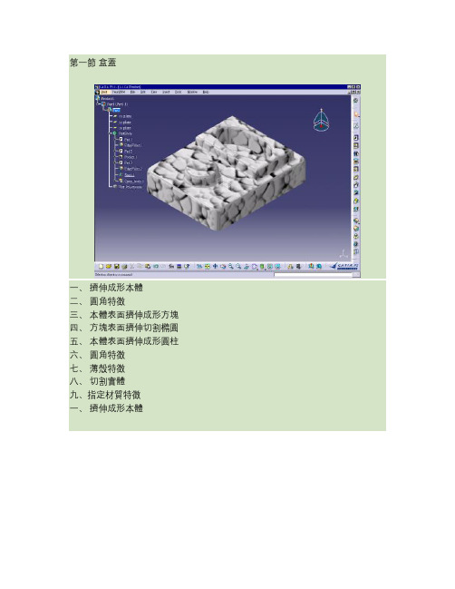
第一節盒蓋一、擠伸成形本體二、圓角特徵三、本體表面擠伸成形方塊四、方塊表面擠伸切割橢圓五、本體表面擠伸成形圓柱六、圓角特徵七、薄殼特徵八、切割實體九、指定材質特徵一、擠伸成形本體1. 選擇零件設計模組在作業系統中按下CATIA)圖示,即出現模組畫面。
在模組選單中選擇Part Design零件設計模組,如下圖中之圈圈所示。
2. 模型樹中選擇xy面將滑鼠游標移至下圖模型樹中圈圈所指之⊕符號,將其次目錄由左至右依序展開,並選擇xy面如下圖右二。
後續步驟將以此xy面為繪製草圖之工作平面。
在繪圖的工作平面中座標系的xy面,會顯示被選取狀態,以不同顏色區分如下圖右一所示。
3. 進入草圖模式在工具箱中選擇圖示進入草圖模式。
所謂草圖模式是在特定的平面上繪製線架構圖元,亦即暫時中止實體模型,而切換至線性架構之繪圖模式。
草圖模式中所產生的線架構圖元,將以擠伸、旋轉或掃略的方式,建構出實體模型之特徵。
在草圖模式中螢幕右側之工具圖示,即變更為線架構圖元之工具圖示,如下圖所示。
4. 繪製矩形草圖在工具箱中選擇圖示,在工具箱中有顯示位置的工具,如果沒有可能隱藏在工具箱的角落中,將它拉出來就可以了,先決定第一點的位置,按下滑鼠左鍵。
向右下角移動滑鼠決定第二點位置,按下滑鼠左鍵。
點選位置下圖中之1.與2.之位置。
矩形之大小及位置可任意決定,後續可變更其長度以及位置。
1.2.5. 標註尺寸在工具箱中連續點選圖示兩次,接著再以滑鼠左鍵分別在下圖中標註出水平與垂直線段之長度和跟原點的距離。
其如下圖所示。
6. 修改尺寸在工具箱中選擇圖示,以滑鼠左鍵雙擊下圖左中的1.之尺寸線,系統即顯示對話框下圖右,提供使用者修改指定之尺寸標註,修改為120mm按下OK鈕。
1.原來垂直長度100mm變成120mm,如下圖左;依序修改各尺寸值,將水平之長度設定為150單位長度,直線至原點距離分別設定為75及60 單位長度,將矩形之中心定位在原點位置,如下圖右所示。
