20B1RS48W3.3LC中文资料
技术要求参数第一包

12、授时模式:支持NTP
Peer,Client/Server,Broadcast/Multicast;
13、加密协议:支持MD5Authentication(RFC1321)、RSA非对称加密、Aulokey;
技术要求(参数)第一包
序
1
NTP时钟服务器
1
1、基于64通道的GPS/北斗双系统授时型接收机,GPS频点L1,北斗频点B1;
2、双系统授时模式下1PPS授时精度不低于20ns;
3、首次锁定时间(TTFF):冷启动V29s,热启动〈Is,重捕获Vls;
4、授时接收灵敏度:跟踪V-163dBm,捕获V-160dBm;
2、形式:RJ45;
3、速度:10/100M自适应,支持手动设置;
4、处理器:不低于32bit,100MHz;
5八内存:N8M;
6、保护:15KVESD/保护、短路保护;
7、支持RS-232和RS-422/485两种类型串口的共存;
8、支持TCP和UDPSocket,每串口可支持不少于6个会话;
9、支持PPP,以及PAP、DHCP等协议,可提供拨入拨出服务;
10
数字签名
服务器
1
1、机架式设备:N2U;
2、通讯接口:N2*1000M;
3、电源:双电源
4、电源功率:N550W;
5、带液晶显示面板;
6、SM2签名:N3000次/秒,SM2骑签:N3000次/秒;
7、SM2制作信封:N2000次/秒,SM2解密信封:>2000次/秒;
8、RSA签名:34500次/秒,RSA骑签:29000次/秒;
(完整word版)铁路通信工题库技能鉴定高级(现场综合维护)
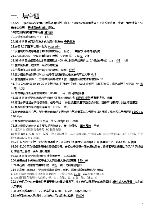
82.雅企610(E1/V.35)按下DIG 为向邻站环回,从本端的V.35(不包括V.35接口电缆)向E1口方向环回,用于68-68+固有损耗302.SDH传输中,最基本的传送模块是_________ STM- 1306.铁路调度指挥系统我们通常用_________表示TDCS309.铁塔单独设置防雷接地体时,接地电阻应不大于_________ 10Ω310.通道测试的最主要指标是_________、衰耗误码率322.800HZ时,会议电话总机的输出输入阻抗应为_________ 600+120325.影响视频比特率的因素: 图像宽度、图像高度、颜色深度、帧率、__________ 压缩因子327.电视电话会议系统呼叫频率是_________HZ 1920353.会议设备所用电源应采用单独供电,供电电源需设总开关,并加__________电源保UPS357. ____________负责小区中的信道分配BSC 基站控制器363.STM-1帧结构由: 段开销、信息净负荷、________________三部分组成管理单元指针366.雅企610(E1/V.35)在面板上打环时,按下__________为向本地环回,从本端的E1口向V.35口环回,用于检测本端设备及连接线是否正常ANA368.直放站漏缆监控接收最低门限值为__________.dBm -60371.基站无线系统中距载频200 kHz以外处绝对功率电平不大于_______dBm -36376.GSM-R维规要求漏缆驻波比测试周期为__________ 1次/年383.目前建成的铁路IP骨干网分为分为核心层、汇聚层、__________三层结构接入层389.分系统环路接口要求外线阻抗为_______W 75390.用以太网方式做网管时,需要接____________接口Ethernet393.视频前端设备主要由编码器、_______________和相关的线缆组成摄像机396.华为0ptix 155/622设备在插板区IU1~IU4槽位不可以插__________。
FANUC数控系统机床电气原理图

YL-569型0i mate MD数控机床实训设备控制柜原理图版本:V14.41、本设备贯彻中华人民共和国机械行业标准JB/T.2739-2008 “工业机械电气图用图形符号”的规定2、本设备贯彻中华人民共和国机械行业标准JB/T.2740-2008 的“项目代号四段标志法”2.1 项目代号采用下列四段标记:第一段 高层代号 前缀符号为 = 例如=D00第二段 位置代号 前缀符号为 + 例如+A1第三段 种类代号 前缀符号为 - 例如-QF1第四段 端子代号 前缀符号为 :例如:103.本图纸还采用了JB2740标准的图区索引法4.代号意义B 总体设计布局及安排,接线板互连图D 电源系统,交流驱动系统N 直流控制系统P 交流控制系统5.斜体下划线表示线号如“5”表示5号线,用于智能化考核系统的输入。
F EDC B F ED图纸说明电 气 原 理 图编 码电气图号设备型号日 期签 字更 改 文 件 号标 记标 记CBAAF 3029285648U 44W 42润滑输出刀库后位输入刀库后位输出刀库前位输入刀库前位计数3813646362616059585756555453冷却排屑5049525351超程刀松刀夹松刀超程5251D E F DE标 记标 记更 改 文 件 号签 字日 期设备型号电气图号编 码电 气 原 理 图XT1表W 4117排屑电机W72V72U72风扇电机W34V34U34321控变380伺变220伺变380冷却电机U 41W32V32U32W31V31U31W1V1U116151413121110987654XT1BC BC输入公共端急停175416气压液位208206气密松刀抱闸24V200204I/O-24V 05CX362616CX41514控变24W 46U 465049启动急停系统24V 伺服24V继板24V 伺服220CX3控变110控变22076555W33V33U331U 43W 43U 43W 42U 42484746454443424140393837363534333231302928272625242322212019181.71.61.51.41.31.21.11.032313029202443.2F 2062021061042024342414039383736353433 2.72.52.32.1 2.62.42.22.03.03.1EDF 5620220420229202108202381360595857565554535251504948474645 3.33.43.53.63.7注:1、①表示端子号,例:①表示XT2:1XT2图电 气 原 理 图编 码电气图号设备型号日 期签 字更 改 文 件 号标 记标 记ED-KA1391.00.7304828PCB2009194681754535251-KA12-KA11XT22726252423222120876543211.21.42.62.42.22.01.61.51.72.12.32.52.71.3 1.1CB162650498167618060-KA18-KA17-KA16-KA15-KA1428191817161514131211100.60.50.40.30.20.10.0B010V24V 24V CBX2.1手摇倍率-XT1055F X2.0Y7.7手摇灯急停2423KP24启动停止222120194321KP24KP24*1RC-L+L DEF 17X11.5X2.5X2.4X2.3X2.2手摇轴选-XT106251816X4.7X11.6X11.7注:1、①表示端子号,例:①表示XT3:11514131211109876Y ZA24V0VX2.6X2.7X4.2XLC*10DE标 记标 记更 改 文 件 号签 字日 期设备型号电气图号编 码电 气 原 理 图XT3图XT3控制面板B C BCY2.5Y2.7Y2.6Y2.4Y2.3Y2.2Y2.1Y2.0F 41U439O 99C 272625EDF 39U43U47U46U422U42U44U4246U4344U434U4348478O 88C 7O 77C 6O 66C 5O 55C 4O 44C 3O 33C 2O 22C46454443424140393837363534333231302928注:1、①表示端子号,例:①表示XT2:1XT2电 气 原 理 图编 码电气图号设备型号日 期签 字更 改 文 件 号标 记标 记EDKA8242322XT5CBKA7KA5KA4KA6Y27Y26Y25PCB2009197Y24Y23Y22Y21KA2KA1KA3Y20500521201918171615141312111098765431010112345678921CB1--接地2--刀库U 3--刀库V 4--刀库W1--空脚2--抱闸0V 3--打刀缸4--抱闸24V 5--主轴气密封F XP1润滑、抱闸E DF XS31刀库电机接插件定义电 气 原 理 图编 码电气图号设备型号日 期签 字更 改 文 件 号标 记标 记ED1--0V2--刀库前位输入3--刀库前位输出4--刀库后位输入5--刀库后位输出6--计数7--空脚8--空脚9--24VWS20-5-KZXS1刀库信号CBWS20-9KZAWS28-12-kZ1--空脚2--主轴风扇U 3--主轴风扇V 4--主轴风扇W 5--冷却电机U 6--冷却电机V 7--冷却电机W 8--排屑电机19--排屑电机210--排屑电机311--照明电源112--照明电源2WS28-4-kZXS41主轴风扇 冷却电机 排屑电机CBA1--空脚2--空脚3--输入公共端4--气压5--松刀6--刀紧7--刀松8--空脚9--空脚10--空脚11--空脚12--空脚1--排屑输入信号2--照明输出信号3--冷却输入信号4--排屑反输出信号5--排屑正输出信号6--冷却输出信号7--M30断电信号8--24V-9--0V-10--刀库反转输出信号11--刀库正转输出信号12--润滑输出信号13--CX314--CX315--抱闸24V 16--抱闸0VF XS81 PLC信号EDF XS71 刀库输入信号接插件定义电 气 原 理 图编 码电气图号设备型号日 期签 字更 改 文 件 号标 记标 记EDWS28-16-kZXS51伺服主电源1--伺服电源1(驱动风扇)2--伺服电源23--伺服电源3(驱动风扇)4--地线CBTYP-5618-k1--空脚2--超程3--超程4--X05--Y06--Z07--X限位8--Y限位9--Z限位10--输入公共端WS24-10-kZXS91 限位信号WS24-12-kZCBWS28-16KTD WS24-10JTD F WS24-12KTD WS24-12-JZXS72 刀库输入信号XS42主轴风扇、润滑电机、冷却电机WS28-12KTD WS28-12-JZWS20-9KTD XS2刀库信号WS20-9JZWS24-10KTD XS92 限位信号WS24-10-JZ XS32刀库电机WS28-4KTD WS28-4-JZ WS20-5KTD XP2润滑、抱闸WS20-5-JZXS82PLC信号WS28-16-JZ备用XS91 限位信号WS24-10-kZ机床侧EDF 备用备用XS52伺服主电源接插件连接图电 气 原 理 图编 码电气图号设备型号日 期签 字更 改 文 件 号标 记标 记EDXS41主轴风扇、排屑电机、冷却电机WS28-12JTD WS28-12-kZXS43主轴风扇、润滑电机、冷却电机WS28-12JTD WS28-12-kZWS28-16JTD WS28-16-kZXS83PLC信号XS33刀库电机WS28-4JTD WS28-4-kZ备用WS28-16JTD WS28-16-kZXS31刀库电机WS28-4JTD WS20-5JTD WS20-9JTD WS28-4-kZXS81PLC信号XP1润滑、抱闸XS1刀库信号WS20-5-KZWS20-9KZCBTYP-233-J XS53伺服主电源TYP-5618-k接线柜侧备用控制柜侧TYP-233-K TYP-233-J WS24-12JTD WS24-12-kZXS71 刀库输入信号TYP-5618-jXS51伺服主电源TYP-5618-kCB技术要求:黑色--交流或直流动力线红色--交流控制线蓝色--直流控制电路白色--直流0V F A电源输入端子NNU422U42W42-KA18=N00/18.D9S9分励脱扣DE-W1L3L2L140A-QS0BC1L11L21L350HZ 40A3相5线 380V 设备总电源(电气控制单元)F 标 记标 记更 改 文 件 号签 字日 期编 码A短路保护NDE设备型号电气图号电 气 原 理 图电路图总电源保护接地铜排L11L12L13BC2L12L22L3=D01/1.B2-QS1 -FU1D40A 32A6mm 2黑色漏电保护F 编 码日 期签 字更 改 文 件 号标 记标 记F 单片机电源AA故障板电源、YL-015-GS3E D CBNL1=D00/1.C94L12A-Q2+5V0V单片机板考核系统电源图电 气 原 理 图电气图号设备型号ED+12V0V故障板CB20.75mm 黑色设故系统电源控制F =P01/1.D8D EF 标 记标 记更 改 文 件 号签 字日 期编 码DE设备型号电气图号电 气 原 理 图伺服主电源图伺服主电源AXS52XS51220V~220V~220V~=D01/2.F5U33V33W33B CA24mmBC。
磁动枪中文教程

)
Rs : (E)
T2 :
(G)
COD:MW3 ,MAG II GUN
()
30
MAG II GUN
,
;, ,
, ,
。( ,
, ,
, ,
, 。)
/
1
5: :
:
,MAG II GUN ,
。 MAG II GUN
31
MAG II GUN
。
MAG II GUN
。
MAG CUBE
/PC
。
:
,MAG II GUN
MAG II GUN 。
MAG II GUN ,
,
MAG CUBE,
, MAG II GUN MAG CUBE
。
8 MAG II GUN MAG CUBE
。
22
MAG II GUN
MAG II GUN MAG CUBE
MAG CUBE
/PC。
MAG II GUN
MAG CUBE
, MAG II GUN
MAG II GUN
。
MAG II GUN
,
MAG II
,
MAG II GUN
G-MATE
。
G-MATE USB
。
MAG II GUN
。 ,MAG II GUN
10 。 ,
,
。
MAG II GUN
,
90
,
MAG II GUN
900 ,MAG II GUN
SELECT
T2 B1 ( )
START
Rs
11
MAG II GUN
MAG CUBE
USB (
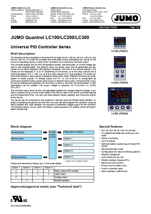
JUMO Quantrol LC100 LC200 LC300式通用PID控制器系列简要描述说明书
Page 1/12JUMO Quantrol LC100/LC200/LC300 Universal PID Controller SeriesBrief descriptionThe Quantrol series is available in the three DIN formats 48mm x48mm, 48mm x96mm, and 96mm x96mm. It is used for two-state and three-state control applications as well as for the control of regulating valves or SCR power controllers via a continuous controller output.The universal analog input for RTD temperature probes, thermocouples, or current/voltage sig-nals is user programmable. The setpoint value, the actual value, and all parameters are dis-played on two seven-segment LED displays (red/green) with one or two decimal place(s). The values can be displayed in °C or °F. Depending on the format, up to five relay outputs with a switching capacity of 3A / 230V or up to four logic outputs 0/14V are available. The switch po-sition of the relays or logic outputs is displayed using yellow LEDs. Different functions can be as-signed to these outputs. An analog output 0to10V or 0(4)to20mA is configurable as continuous controller output, actual value output, or setpoint value output. Using the binary input, the device settings and operation can be locked, a ramp or the timer can be activated, or self-optimization can be initiated. The supply voltage is optionally AC110to240V or AC/DC 20to30V.The controller has a ramp function with adjustable gradient for constant setpoint change. In ad-dition, a special firing curve for small pottery kilns can be used which allows controlled starting and time dependent firing. The user can enter setpoint values, gradient, and firing time directly at the device.The device can be connected to host systems or devices using the RS485 serial interface. In-stead of operating the device from the front, the user can also program the controller using the setup program and USB interface; this requires no additional voltage supply for the controller. The Quantrol series, like all JUMO controllers, is also equipped with reliable JUMO self-optimi-zation (autotuning).LC100 (702031) LC200 (702032)LC300 (702034)Block diagramOption 1Option 2Option 3Option 4X X X X Relay output (N/O contact) X X X X Logic outputX Analog outputX RS485 interface Special features•48 × 48, 48 × 96, 96 × 96 mm formats •Two-state/three-state and continuous con-troller•Sensor monitoring•Up to 5 outputs•Self-optimization (autotuning) for exact PID control•Manual/automatic mode•Configurable limit value monitoring (alarms)•Setpoint changeover•Level inhibit and key lock•RS485 interface (Modbus RTU)•Ramp and timer function•Firing curve for pottery kilns•Push-in controller insert•Setup interface (USB Mini-B)Approvals/approval marks (see "Technical data")Data Sheet 702030Data Sheet 702030Page 2/12DescriptionSelf-optimization (autotuning)Standard features include the tried and tested self-optimization (oscillation method), which makes it possible for the controller to be matched to the control loop by a user who is not a control technology expert. Here, the re-action of the control path to the specific vari-able changes is evaluated and the controller parameters proportional band, reset time, de-rivative time, cycle time, and filter time con-stant are calculated.Ramp functionThe ramp function is used for a constant change of setpoint value w up to the ramp limit value SP (entered setpoint value). A rising or a falling edge arises depending on the actual value at the time of ramp start t0. The slope is defined by a gradient which is entered during the controller configuration.Firing curveThe firing curve is used for controlled starting and time-dependent firing of small pottery kilns. The user can enter setpoint values, gra-dient, and firing time directly at the device.Limit value monitoringThe controller is equipped with two limit value monitoring functions, each with eight configu-rable alarm functions. Any analog signals can be selected as actual and setpoint value from a selector. When a limit value is exceeded, a signal can be displayed or an internal control-ler function initiated. With the limit value mon-itoring, extensive alarm and limit valuefunctions can be implemented.TimerThe timer is started manually or automatically (after power on, for example). When the timer expires, the timer output signal changes its state (configurable). The timer can be used to implement functions like time-limited control or setpoint changeover.Setup programThe setup program provides the user with aneasy and comfortable way to configure the controller using a PC.The PC has to be connected to the controllers USB interface (Mini-B type) with a USB cable.Thereby the controller is powered over the USB interface. As a result, no mains supply is required during the configuration.Data Sheet 702030Page 3/12Controller parametersAll the parameters and their meanings are included in the table. Some parameters may be missing or meaningless for a particular type of controller.Technical dataThermocouple inputRTD temperature probe inputParametersValue range Factory setting MeaningProportional band 1 (Pb1)0 to 9999 digit 0 digit Size of the proportional bandThe controller structure is not effective with Pb = 0 (behavior identical to limit value monitoring). For a continuous controller, Pb1 must be >0.Proportional band 2 (Pb2)0 to 9999 digit 0 digit Derivative time (dt)0 to 9999 s 80 s Influences the differential component of the controller output signal Reset time (rt)0 to 9999 s 350 s Influences the integral component of the controller output signal Cycle time 1 (Cy1)0to 999.9 s 20.0 s When using a switched output, the cycle time should be chosen so that the energy supply to the process is as continuous as possible without overloading the switching elements.Cycle time 2 (Cy2)0.0to 999.9 s 20.0 sec Contact spacing (db)0.0to 999.9 digit0.0 digit Spacing between the two control contacts of the three-state controller Switching differential 1 (HyS1)0.0to 999.9 digit 1.0 digit Switching differential of a switching controller with proportional band Pb =0 (behavior identical to limit value monitoring)Switching differential 2 (HyS2)0.0to 999.9 digit 1.0 digit Working point (y0)-100 to +100 %0 %Output level for P and PD controller (if x = w then y = y0)Output value limit 1 (y1)0 to 100 %100 %Maximum output value limit (only effective if Pb > 0)Output value limit 2 (y2)-100 to +100 %-100 %Minimum output value limit (only effective if Pb > 0)Description StandardMeasuring range a a This information refers to the ambient temperature of 20°C. Measuring accuracy b bIncl. measuring accuracy at the cold junction.The accuracy values refer to the measuring range.Ambient temperatureinfluence Fe-CuNi "L"Fe-CuNi "J"Cu-CuNi "T"NiCr-Ni "K"NiCr-CuNi "E"NiCrSi-NiSi "N"Pt10Rh-Pt "S"Pt13Rh-Pt "R"EN 60584EN 60584EN 60584EN 60584EN 60584EN 60584EN 60584-150 to +900 °C -200 to +1200 °C -200 to +400°C -200 to +1372 °C -200 to +1000 °C -100 to +1300 °C -40 to +1768 °C -40 to +1768 °C≤ 0.4 %≤ 0.4 %≤ 0.4 %≤ 0.4 %≤ 0.4 %≤ 0.4 %≤ 0.4 %≤ 0.4 %≤ 100 ppm/K ≤ 100 ppm/K ≤ 100 ppm/K ≤ 100 ppm/K ≤ 100 ppm/K ≤ 100 ppm/K ≤ 100 ppm/K ≤ 100 ppm/KCold junction: KTY internalDesignation,connection type Measuring range Measuring accuracy aAmbient temperature influence Pt100 EN 607512-wire connection 3-wire connection -200 to +650 °C≤ 0.4 %≤ 0.4 %≤ 50 ppm/KPt1000 EN 607512-wire connection 3-wire connection -200 to +650 °C≤ 0.4 %≤ 0.4 %≤ 50 ppm/KKTY , R 25 = 1000 Ω2-wire connection -50 to +150 °C≤ 1.0 %≤ 50 ppm/K KTY , R 25 = 2000 Ω2-wire connection -50 to +80 °C≤ 1.0 %≤ 50 ppm/K Cu-503-wire connection-50 to +200 °C≤ 1.0 %≤ 50 ppm/KData Sheet 702030Page 4/12Input for standard signalsBinary inputMeasuring circuit monitoringIn the event of a malfunction, the outputs move to a defined (configurable) status.OutputsProbe wire resistance: max. 30 Ω per wire with 3-wire circuitMeasuring current: Pt100 approx. 1 mA; Pt1000 and KTY approx. 100 μALead compensation: not required for 3-wire circuit. For a 2-wire circuit, the lead resistance can be compensated by correcting the actual value.aThe accuracy values refer to the measuring range.Measuring range Measuring accuracy a aThe accuracy values refer to the maximum measuring range.Ambient temperature influence Voltage 0 to 10 VInput resistance > 650k Ω≤ 0.4 %≤ 150 ppm/K Current 0(4) to 20 mA Voltage drop > 2.2V≤ 0.4 %≤ 100 ppm/KInput for potential-free contactOpen = inactive;Closed = activeMeasuring probe Overrange/underrangeProbe/cable short circuitProbe/cable breakThermocouple•-•RTD temperature probe •••Voltage 0 to 10V ---Current 4to 20 mA •••Current 0to 20 mA---• = detected - = not detectedRelay (N/O contact)Contact rating Contact lifeMax. 3 A at 230 V AC resistive load 150,000 operations at nominal load 350,000 operations at 1310,000 operations at 1 A and cos ϕ > 0.7Logic output 0/14V / 20mA max.Voltage (option)Output signal Load resistance Accuracy 0 to 10V > 600 Ω < 0.5 %Current (option)Output signals Load resistance Accuracy0 to 20 mA / 4 to 20 mA < 450 Ω< 0.5 %Designation,connection typeMeasuring rangeMeasuring accuracy aAmbient temperature influenceData Sheet 702030Page 5/12ControllerController type Two-state controller, three-state controller, continuous controllerController structures P/PI/PD/PIDSampling rate250 msA/D converter16-bit resolutionTimerAccuracy0.8% ± 10ppm/K ± 250msElectrical dataVoltage supply (switch mode PSU)AC110 to 240V +10/-15 %, 48 to 63HzAC/DC 20 to 30V, 48 to 63HzElectrical security Acc. to DIN EN 61010, part 1; overvoltage category III, pollution degree 2Power consumption Max. 14 VAElectrical connection On the rear via screw terminals; with core-end ferrule of a pipe shape, open cable lug or pin cable lug Conductor cross section Fine-strand 0.25 to 1.5 mm2Tightening torque0.5NmElectromagnetic compatibility Acc. to DIN EN61326-1Interference emission Class A - only for industrial use -Interference immunity Industrial requirementsSetup interface USB socket, type Mini-B 5-poleRequirements for core-end ferrules and cable lugsCore-end ferrule Pipe shape, without plastic sheath acc. to DIN 46228 part 1,with plastic sheath acc. to DIN 46228 part 4Cable lug Open crimp cable lug, dimensionally adapted to DIN 46237 for closed crimp cable lugsPin cable lug Acc. to DIN 46231For UL applications Use of the cable lugs or ferrules acc. to UL 486A-B (UL listed or recognized)Case and ambient conditionsCase type Plastic case for panel mounting acc to. IEC 61554 (indoor use)Dimensions (front)LC100: 48mm x 48mm; LC200: 48mm x 96mm (portrait format);LC300: 96mm x 96mmWeight (fully fitted)LC100: approx. 150 g; LC200: approx. 200 g; LC300: approx. 300 gProtection class Acc. to DIN EN 60529, at the front IP 65, at the rear IP 20Operating position AnyPanel cut-out LC100: 45mm x 45mm; LC200: 45mm x 92mm;LC300: 92mm x 92mmMinimum spacing horizontal/vertical LC100: 11mm / 30mm (65mm with USB cable);LC200/LC300: 22mm / 30mm (65mm with USB cable)Depth behind panel LC100: max. 95mm; LC200/LC300: max.80 mmAmbient/storage temperature range-5 to +55 °C/-40 to +70 °CClimatic conditions Rel. humidity < 90 % annual average, without condensationSite altitude Up to 2000 m above sea levelData Sheet 702030Page 6/12Interface7-segment displaysApprovals/approval marksInterface type RS485Protocol Modbus RTU Baud rate 9600, 19200Data format 8 data bits, no parity bit, 1 stop bit Device address 0 to 254No. of subscribersMax. 32Digit height LC100, LC200Upper display: 10 mm; lower display: 7 mm LC300Upper display: 20 mm; lower display: 13 mm Color Upper display: red; lower display: green Places 4 (including decimal places)Decimal places 0, 1, 2 (configurable)Display range-1999 to 9999Approval mark Testing agencyCertificate/certification number Inspection basis Valid for c UL usUnderwriters LaboratoriesE201387UL 61010-1,CAN/CSA C22.2No. 61010-1all versionsData Sheet 702030Page 7/12DimensionsLC100Data Sheet 702030Page 8/12 LC200Data Sheet 702030Page 9/12 LC300Minimum spacing of panel cut-outsType Without USB cable With USB cableHorizontal Vertical Horizontal VerticalLC10011 mm30 mm11 mm65 mmLC20022 mm30 mm22 mm65 mmLC30022 mm30 mm22 mm65 mmData Sheet 702030Page 10/12 Display and control elements(A)(B)(C)(D)The software version is displayed on the device whensimultaneously pressing keys (A) and (C).Electrical isolationConnection diagramThe connection diagram in the data sheet provides preliminary information about the connection possibilities. For the electrical connection only use the brief instructions or the operating manual. The knowledge and the correct technical execution of the safety information/instructions con-tained in these documents are mandatory for installation, electrical connection, and startup as well as for safety during operation.The terminal strips on the device rear are equipped with screw terminals. Please refer to the technical data for specifications concerning the con-ductor cross section.Data Sheet 702030Page 11/12Data Sheet 702030Page 12/12Order details(1)Basic type702031Quantrol LC100 (format 48mm x48 mm) 1x analog input (universal), 1x binary input a, 1x relayoutput (N/O contact)702032Quantrol LC200 (format 48mm x96mm, portrait format) 1x analog input (universal), 1x binaryinput a, 1x relay output (N/O contact)702034Quantrol LC300 (format 96mm x96mm) 1x analog input (universal), 1x binary input a, 1x relayoutput (N/O contact)(2)VersionX X X8Standard with factory settingsX X X9Customer-specific configuration (specifications in plain text)(3)Option for expansion slot 1X X X0Not usedX X X1 1 relay output (N/O contact)X X X2 1 logic outputX X X3 1 analog output (configurable)(4)Option for expansion slot 2X X X0Not usedX X X1 1 relay output (N/O contact)X X X2 1 logic outputX X X4 1 RS485 interface(5)Option for expansion slot 3X X X0Not usedX X1 1 relay output (N/O contact)X X2 1 logic output(6)Option for expansion slot 4X X X0Not usedX X1 1 relay output (N/O contact)X X2 1 logic output(7)Voltage supplyX X X23AC110to240V+10/-15%, 48to63HzX X X25AC/DC20to30V, 48to63Hza Binary input for potential-free contact (usable alternatively to analog input DC0to10V).(1)(2)(3)(4)(5)(6)(7)Order code/--Order example702034/8-3412-23Scope of delivery1 controller in the ordered version (including seal and fastening elements)1 Brief Instructions B702030.7 in DIN A6 format (multilingual)AccessoriesDescription Part no.USB cable, A-connector to Mini-B-connector, length 3m00506252。
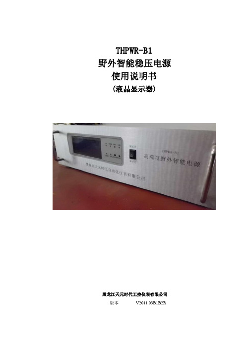
B1R_B2R电源说明书
THPWR-B1野外智能稳压电源使用说明书(液晶显示器)黑龙江天元时代工控仪表有限公司版本V2011.03B1B2R感谢您购买本公司产品!请在使用前仔细阅读本说明书,按说明书规定使用本产品。
因本产品技术含量高,需要使用者具有一定的专业知识。
并请耐心地反复多次阅读,才能读懂本说明书、用好本设备。
如有疑问请向本公司咨询。
前面板说明□1 交流指示灯 灯亮为有交流接入设备,灯灭为无 □2 逆变器指示灯 灯亮显示为逆变器正常工作,灯灭为切断逆变或逆变异常 □3 负载一指示灯 灯亮为负载一正常工作,灯灭为负载一停止工作或者出现异常□4 负载二指示灯 灯亮为负载二正常工作,灯灭为负载二停止工作或者出现异常□5 太阳能指示灯 灯亮为太阳能正常工作,灯灭为太阳能为接入设备或太阳能出现异常□6 直供指示灯 灯亮显示为交流直接供电模式,灯灭为其他供电模式 □7 直供/隔供切换按钮 切换直供模式与隔供模式 □8 复位按钮 使设备恢复到最出状态 □9 开关按钮 按钮置于ON 的位置为开机,置于OFF 为关机后面板说明□1 负载一的正极 与测控设备的正极相连接 □2 负载一的负极 与测控设备的负极相连接 □3 负载二的正极 与通信设备的正极相连接 □4 负载二的负极 与通信设备的负极相连接 □5 逆变输出 与逆变器相连接 □6 电池一接入端 与蓄电池一相连接 □7 电池二接入端 与蓄电池二相连接 □8 太阳能充电器接入端 与太阳能充电器相连接 □9 交流输入端 通过连接线与交流设备相连接 □10 SIM 卡插入口 SIM 卡通过卡托插入此口 □11 短信信号指示灯 灯一分钟闪一次为短信信号正常,频繁闪烁为异常 □12 天线接入端 天线通过此孔接入设备□13网口通过网线与交换机相连接目录1 用途 (1)2 技术规格 (1)2.1 输入 (1)2.2 输出 (1)2.3 内置充电器 (1)2.4 蓄电池 (2)3 使用环境要求 (2)3.1室内 (2)3.2 防雷设施 (2)4 安装及接线 (2)5 运行 (3)5.1 概述 (3)5.2 正常运行时的显示 (4)5.3 保护充电 (4)5.4 故障 (4)5.5 三类供电模式的切换 (5)6 通信 (6)6.1 RS485通信口 (6)6.2 网络通信口---IP (6)6.3 短消息模块 (6)7 更换蓄电池 (8)8 复位 (8)附表 (9)1 用途THPWR-B1野外智能稳压电源(简称设备)是在郊外无人值守的室内使用的电源设备,专为直流电气装置供电。
RS IDM-20便携迷你多用数字万用表说明书

交 / 直流电压
直 / 交流电压 600V
uA , mA 交 / 直流电流
Hale Waihona Puke 200mA/500V 快速熔断保险丝
电阻 , 二极管,短路测试
直 / 交流电压 600V
1
便携迷你多用数字万用表
当电压高于 25VAC 或 35VDC 时测试要十分小心,否则会导致电击。 在进行二极管、电阻、短路测试时,应把电容放电并断开电源。 如果存放时间长,应取出电池。
精确度 ±(0.5% rdg + 3d) ±(1.2% rdg + 3d) ±(1.0% rdg + 8d) ±(2.3% rdg + 10d) ±(2.0% rdg + 8d)
±(2.5% rdg + 10d) ±(0.8% rdg + 5d)
±(1.2% rdg + 5d)
±(5.0% rdg + 5d) ±(10.0% rdg + 5d)
6.5 二极管测试
将功能旋钮扭至
档位。
按 MODE 键液晶显示屏显示 。
把表笔与二极管相接触,正向电压将显示 400 至 700mV。反向电压显示 “OL”符号 . 短路时将显示接近 0V,开路时会在两种极性上显示“OL”符号。
6.6 非接触交流电压测试
警告:谨防电击 . 在使用前 , 请确认仪表的非接触电压探测器工作正常。 将仪表顶部非接触电压探测器靠近或者插入插座的火线端。 如果有交流电压存在,指示灯将一直点亮。
3
便携迷你多用数字万用表
最大输入电压 二极管测试 短路蜂鸣测试 显示 过载提示 极性 低电量提示 输入阻抗 交流响应 交流电压频宽 自动关机 保险丝 电池 操作温度 储存温度 重量 尺寸 标准
RP20-4812DEW资料
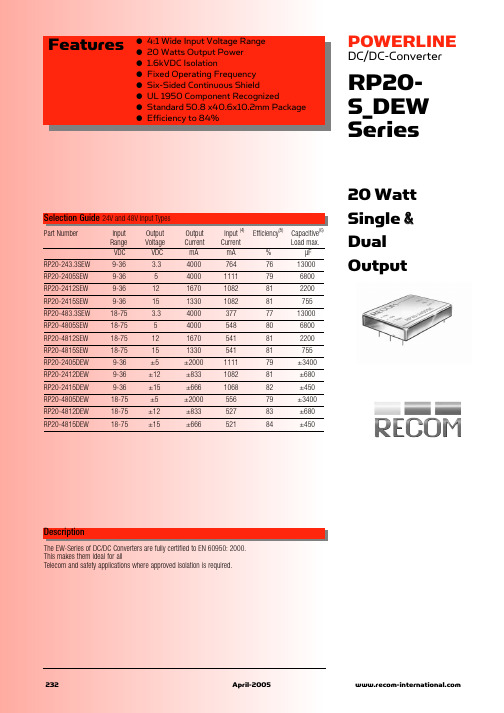
Features
● ● ● ● ● ● ● ●
4:1 Wide Input Voltage Range 20 Watts Output Power 1.6kVDC Isolation Fixed Operating Frequency Six-Sided Continuous Shield UL 1950 Component Recognized Standard 50.8 x40.6x10.2mm Package Efficiency t(25% to 100% FL)
Cross Regulation (Note 9) Ripple and Noise (20MHz bandwith)
Temperature Coefficient Transient Response (25% load step change) Over Voltage Protection Zener diode clamp (only single)
Minimum Load (see Note 1)
元器件交易网
POWERLINE
DC/DC-Converter
Specifications (typical at nominal input and 25°C unless otherwise noted)
Line Regulation (LL-HL at full load) Single (W) Dual (W) Auxiliary Single Dual Auxiliary Dual Auxiliary Single Dual Auxiliary
232
April-2005
元器件交易网
POWERLINE
DC/DC-Converter
三菱FX2N-48MR PLC 介绍

辽宁石油化工大学实习设计本(第册)专业班级:电气自动化技术0832班姓名:夏姣姣学号:18号实习、设计名称:顶岗实践实习、设计地点:江苏长乐纤维科技有限公司实习、设计时间:2011 年3 月5 日至2011 年4 月29 日指导教师:牟淑杰杨贵义成绩:评阅人:职业技术学院教务科目录前言 (1)1.总体设计 (1)1.1 功能介绍 (1)1.2 总体构想 (1)1.3 元器件的选择 (2)2.硬件设计 (2)2.1 控制元件—PLC (2)2.1.1 三菱FX2N-48MR PLC 介绍 (2)2.1.2 三菱FX2N-48MR PLC技术参数 (3)2.1.3 三菱FX2N-48MR PLC开发环境 (3)2.2 检测元件—磁性开关 (4)2.2.1 D-C73型磁性开关的技术参数 (4)2.2.2 D-C73型磁性开关的工作原理 (5)2.2.3 D-C73型磁性开关的安装要求 (5)2.3 气缸 (6)2.3.1 CDM2B20-45型气缸 (6)2.3.2 CDJ2B10-60-B 气缸 (6)2.3.3 气缸的工作原理 (7)2.4 电磁阀 (7)2.4.1 4V120-60电磁阀的技术参数 (7)2.4.2 4V120-60电磁阀的工作原理 (8)2.4.3 4V120-60电磁阀的安装要求 (8)3.软件设计 (8)3.1 I/O分配表 (8)3.2 流程图 (9)3.3 主程序梯形图 (11)4.实例说明 (12)4.1 加工单元控制系统 (12)4.1.1 工作任务 (12)4.1.2 PLC的分配及系统安装接线 (12)4.4.3 编写和调试PLC控制程序 (14)4.2 装配单元PLC控制系统设计 (16)4.2.1 工作任务 (16)4.2.2 PLC的分配及系统安装接线 (16)4.2.3 编写和调试PLC控制程序 (19)5.总结 (20)参考文献 (21)前言本实训指导书主要阐述三菱FX2N-48MR PLC型自动生产线实训考核装备的基本结构、工作原理和工作过程。
RS1A40D40中文资料

Specifications are subject to change without notice (28.02.01)1Rated opera-Non-rep. Control Rated operational current tional voltage voltage voltage 10 A 25 A 40 A 230 VACrms 650 V p 4.5-32 VDC RS1A23D10RS1A23D25RS1A23D4018-36 VAC/DC RS1A23LA10RS1A23LA25RS1A23LA40400 VACrms 850 V p 4.5-32 VDC RS1A40D10RS1A40D25RS1A40D40480 VACrms1200 V p4.5-32 VDC RS1A48D10RS1A48D25RS1A48D4018-36 VAC/DCRS1A48LA10RS1A48LA25RS1A48LA40•Zero switching AC Solid State Relay•Direct copper bonding (DCB) technology •LED indication• Clip-on IP 20 protection cover •Self-lifting terminals•Housing free of moulding mass•2 input ranges: 4.5-32 VDC and 18-36 VAC/VDC •Operational ratings up to 40 AACrms and 480 VAC •Non-repetitive voltage: Up to 1200 V p •Opto-insulation: > 4000 VACrmsProduct DescriptionThe zero switching relay with triac (10 A) or alternistor out-put (25 A, 40 A) is an inex-pensive solution for resistive loads. The zero switching relay switching relay switch-es ON when the sinusoidal curve crosses zero andSolid State Relaysswitches OFF when the cur-rent crosses zero. The LED indicates the status of the control input. The clip-on cover is securing touch pro-tection to IP 20. Output ter-minals can take cables up to 16 mm 2.Type SelectionSwitching mode Rated operational Rated operational Control voltage voltage current A: Zero Switching23: 230 VACrms 10: 10 AACrms LA: 18 - 36 VAC/VDC 40: 400 VACrms 25: 25 AACrms D: 4.5 - 32 VDC48: 480 VACrms40: 40 AACrmsSelection GuideIndustrial, 1-Phase ZS w. LED Types RS 23, RS 40, RS 48General Specifications2Specifications are subject to change without notice (28.02.01)RS1AOutput SpecificationsThermal SpecificationsInput SpecificationsInsulationHousing SpecificationsSpecifications are subject to change without notice (28.02.01)3RS1ADimensionsFunctional DiagramWiring DiagramHeatsink Dimensions (load current versus ambient temperature)RS10.3.14 2.38 1.610.840.07-4.05 3.17 2.29 1.410.53-5.21 4.18 3.16 2.13 1.110.086.72 5.50 4.29 3.07 1.860.648.767.295.82 4.35 2.88 1.4111.659.827.996.164.33 2.4916.013.711.298.90 6.524.1423.520.116.813.510.23 6.9238.433.228.122.917.712.53-----29.510.09.08.07.06.05.04.03.02.01.0Loadcurrent [A]Thermal resistance [K/W]T AAmbient temp. [°C]Powerdissipation [W]1412119765321203040506070RS25.1.92 1.61 1.30 1.000.690.392.39 2.04 1.69 1.340.990.633.00 2.59 2.18 1.77 1.360.953.68 3.19 2.71 2.22 1.74 1.254.49 3.90 3.32 2.73 2.14 1.565.64 4.91 4.18 3.45 2.72 1.997.396.445.49 4.55 3.60 2.6510.349.037.716.395.073.7516.314.212.210.118.055.99--25.721.417.012.725.022.520.017.515.012.510.07.55.02.5Loadcurrent [A]Thermal resistance [K/W]T AAmbient temp. [°C]Powerdissipation [W]33282421171411852203040506070Junction to ambient thermal resistance, R th j-a < 40.0 K/W Junction to BTB tab thermal resistance, R th j-t < 2.00K/W BTB tab to case thermal resistance, R th t-s < 2.80K/W Case to heatsink thermal resistance, R th c-s < 0.20K/W Maximum allowable BTB case temperature 100deg.C Maximum allowable junction temperature 125deg.CJunction to ambient thermal resistance, R th j-a < 20.0 K/W Junction to case thermal resistance, R th j-c < 1.10K/W Case to heatsink thermal resistance, R th c-s < 0.20K/W Maximum allowable case temperature 100deg.C Maximum allowable junction temperature 125deg.C4Specifications are subject to change without notice (28.02.01)RS1ACarlo Gavazzi Heatsink Thermal ...for power(see Accessories)resistance... dissipation No heatsink required ---N/ARHS 300 5.00 K/W > 0 W RHS 100 3.00 K/W > 25 W RHS 45A 2.70 K/W > 60 W RHS 45B 2.00 K/W > 60 W RHS 90 1.35 K/W > 60 W RHS 45A plus fan 1.25 K/W > 0 W RHS 45B plus fan 1.20 K/W > 0 WRHS 112 1.10 K/W > 100 W RHS 3010.80 K/W > 70 W RHS 90 plus fan 0.45 K/W > 0 W RHS 112 plus fan 0.40 K/W > 0 W RHS 301 plus fan 0.25 K/W > 0 W Consult your distribution > 0.25 K/W N/A Infinite heatsink - No solution ---N/AHeatsink SelectionHeatsink Dimensions (cont.)RS40..1.100.890.680.470.260.051.41 1.180.940.700.460.221.81 1.54 1.260.980.700.432.33 2.01 1.68 1.35 1.030.702.95 2.56 2.16 1.77 1.380.983.713.22 2.73 2.24 1.75 1.274.85 4.22 3.59 2.96 2.33 1.696.785.915.03 4.16 3.29 2.4110.659.307.946.58 5.23 3.8722.319.516.713.911.18.2540.036.032.028.024.020.016.012.08.04.0Loadcurrent [A]Thermal resistance [K/W]T AAmbient temp. [°C]Powerdissipation [W]484236312520161174203040506070Junction to ambient thermal resistance, R th j-a < 20.0 K/W Junction to case thermal resistance, R th j-c < 0.90K/W Case to heatsink thermal resistance, R th c-s < 0.20K/W Maximum allowable case temperature 100deg.C Maximum allowable junction temperature 125deg.CFast-on terminalsAll accessories can be ordered pre-assembled with Solid State Relays.Other accessories include DIN rail adaptors, fuses, varistors and spacers.For futher information refer to Accessories datasheets.•Fast-on tabs•Type R..F .•Screw mounted fast-on terminals•Flat (0°) and angled (45°) orientation•Input tab width: 4.8mm • Output tab with: 6.3mm •Tab dimensions accord-ing to DIN 46342 part 1•Pure tin-plated brassRS, RM Solid State Relay Fast-on terminals Tab orientationOrdering KeyRS1A48D40 F 4*0: Flat (0º)4: Angled (45º)*Other Accessories•Heatsinks and fans •Type RHS....•0.25 to 5.00 k/W •Single and dual relay types•Touch safety cover •Type RMIP20•IP20 protection degree •Pack size: 20 pieces。
台湾泛达温控仪表
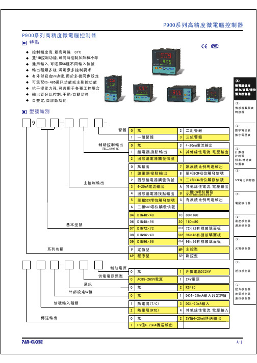
13
ON OFF ON
PV
16
ON
LOW
HIGH
LOW
(Timer )
OFF HIGH
PV
19
AL1-3 Hour/Min 00.00-99.59
(C)
(D) /
(E) SCR (F)
(G)
(H)
(I)
(J)
A-7
P900
LEVEL1
(
)
5
5
*60
LEVEL1(
)
*
A/M 2
LEVEL1(
)
LEVEL2 (PID ) 5
(I)
(J)
A-3
P900
(
)
A.
1
2
AC85-265V
DC15-50V(Option )
3
P907/P910 4
5
6
7
15
8
16 9
17 10
18 11
19 12
20 13
21 14
B.
OUT1
OUT2
Relay
NC
5
6 NO
COM
7
SSR mA.V
RelaySSRmA.V 3
4
C.
mA.V
RTD TC.mV
2
(RTD )
3 DC4-20mA
4
,
0 1 PV 4-20mA
2 SV 4-20mA
A-1
P900
(TC ) (RTD )
(mA ) (mV,V )
(Relay ) (SSR) (mA ) (V )
PID
, (Relay )
Electronic transport in two dimensional graphene
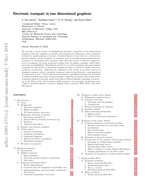
arXiv:1003.4731v2 [cond-mat.mes-hall] 5 Nov 2010
(Dated: November 9, 2010)
We provide a broad review of fundamental electronic properties of two-dimensional graphene with the emphasis on density and temperature dependent carrier transport in doped or gated graphene structures. A salient feature of our review is a critical comparison between carrier transport in graphene and in two-dimensional semiconductor systems (e.g. heterostructures, quantum wells, inversion layers) so that the unique features of graphene electronic properties arising from its gapless, massless, chiral Dirac spectrum are highlighted. Experiment and theory as well as quantum and semi-classical transport are discussed in a synergistic manner in order to provide a unified and comprehensive perspective. Although the emphasis of the review is on those aspects of graphene transport where reasonable consensus exists in the literature, open questions are discussed as well. Various physical mechanisms controlling transport are described in depth including long-range charged impurity scattering, screening, short-range defect scattering, phonon scattering, many-body effects, Klein tunneling, minimum conductivity at the Dirac point, electron-hole puddle formation, p-n junctions, localization, percolation, quantum-classical crossover, midgap states, quantum Hall effects, and other phenomena.
丹佛斯变频器 FC101_样本_中文_V1
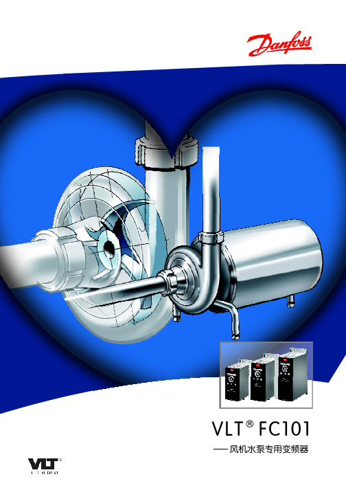
FC- 1 0 1 P
T
[ 7- 1 0 ]功 率 型 号
PK25
0.25kW
PK37
0.37kW
PK75
0.75kW
P1K5
1.5kW
P2K2
2.2kW
P3K0
3kW
P3K7
3.7kW
P5K5
5.5kW
P7K5
7. 5 k W
P11K
11kW
P15K P18K P22K P30K P37K P45K P55K P75K P90K
PLC接线图
KA2
12 24V电压
反馈信号 10V电压 50
18
模拟电压输出0~10V 53
GND 55
FC101
1
RELAY1
频率上限
2
4
RELAY2
压力上限
5
F C 10 1接 线 图 3
专业化功能
VLT® FC101是一款高质量的丹佛斯产品,专为风机、水泵的OEM客户量身定制。
特点
益处
标 准 内 置HV AC 软 硬件 功 能-降 低控 制 系统 投 资成 本
变频恒压供水系统特点:
1、 节能 高 效 直接利用市政管网压力,降低了供水系统实际提供的压力 2、清洁卫生 取消传统水箱,从根本上杜绝了水在箱内污染的可能,显著提高饮用水水质,并可实现无泵房供水 3、安全可靠 自动监控泵前市政管网的压力变化,并采取相应保护措施,保证市政管网运行的安全可靠 4、节约投资 5、智能控制
电缆长度和横截面积 最大电控机电缆长度,屏蔽/铠 装 最大 电 控机 电 缆 长 度, 非 屏 蔽/非 铠装 控制端子电缆(刚性)的最大截面积 控制端子电缆(柔性)的最大截面积
打印机指令说明V204
B3. 指令集汇总
本指令集含如下类别: - 设置指令 - 标签格式指令 - 通过串口的交互指令 - 对象下载指令
3 / 39
索引
指令 T B b C H EI EK ES FE FI FK FR FS GG GI GK GM GW I JB JF FM MD
描述 打印文本 打印一维条码 打印二维条码 计数器(counter) 热度设置** 打印软字体名称 删除软字体 下载软字体 结束表格存储(form) 打印表格名称 删除表格 执行表格 表格存储 打印图形 打印图形列表(list) 删除图形 存储图形 打印二进制格式图形 选择字符集** 设置回转功能无效** 设置回转功能有效** 命令打印机走一行标签 校准纸张感应器
5 / 39
Tp1,p2,p3,p4,p5,p6,p7,”DATA”<CR> Tp1,p2,p3,p4,p5,p6,p7,Cn<CR> Tp1,p2,p3,p4,p5,p6,p7,Vn<CR> Tp1,p2,p3,p4,p5,p6,p7,”DATA”Cn<CR> Tp1,p2,p3,p4,p5,p6,p7,”DATA”Vn<CR> Tp1,p2,p3,p4,p5,p6,p7,Combo <CR>
6 / 39
W1 打印输出:
B命令: 打印一个条码
语法: Bp1,p2,p3,p4,p5,p6,p7,p8,”DATA”<CR> Bp1,p2,p3,p4,p5,p6,p7,p8,Cn<CR> Bp1,p2,p3,p4,p5,p6,p7,p8,Vn <CR> Bp1,p2,p3,p4,p5,p6,p7,p8,”DATA”Cn <CR> Bp1,p2,p3,p4,p5,p6,p7,p8,”DATA”Vn<CR> Bp1,p2,p3,p4,p5,p6,p7,Combo <CR>
DSP应用技术-工程应用实例
20 K
30 k
3C11
RXB
RX B
14
CLKFLTA D
1u CL K FL TA D 3
4
A V CC
AVCC 3R8
13 V+
IN CL K V-
ou t 11
op ou t op in
5 6
GND 12
3R9
20 K
2
3 3R10
+2 .5 V
U10 MA X 29 5EW E
31R020
NC NC
7 GND 16
AGND 27 AGND
3R3 10 k
3R6 10 k
15 D0 14 D1 13 D2 12 D3 11 D4 10 D5 9 D6 6 D7 5 D8 4 D9 3 D10 2 D11 1 28
TI
T
I
TQ
T
Q
D [0..1 1] D [0..1 1]
图7.7 模拟输入/输出通道电路
工程应用实例
1. 信号流程
(1) 接收信号流程 由射频部分送来的基带DQPSK调制信号 (f0=7.2 kHz),进入带通滤波器MAX295EWE,滤除带外噪声, 然后进入运算放大器(TL084)放大至适当电平(0~3 V变化范围)。 放大后的信号由模数转换器AD7862进行量化,量化后的数据进 入DSP芯片,通过软件编程进行DQPSK解调、维特比译码和解 交织等,得到原始信息码。DSP将该信息码送给Intel8251A,转 化成9.6 kb/s的UART数据流,最后经MAX232EESE转变成RS232电平(±12 V)送往数据终端。
7.6 DSP
工程应用实例
图
主 系 统 及 部 分 外 围 电 路
位移传感器的原理及应用

2021/2/4
3366
涂层厚度仪
测量线路板的铜膜厚度
2021/2/4
3377
转速测量
在一个旋转体上开一条或数条槽如图3.2.15(a)所示,或者做
成齿,如图3.2.15(b)所示,旁边安装一个涡流传感器。当旋
转体转动时,涡流传感器将周期性地改变输出信号,此电压
经过放大、整形,可用频率计指示出频率数值。此值与槽数
2021/2/4
19
微小位移的测量
1-测端 2-防尘罩 3-轴套 4-圆片簧 5-测杆 6-磁筒 7-磁芯 8-线圈 9-弹簧 10-导线
2021/2/4
20
电感式滚柱直径分选装置
3.2.8 滚柱直径分选装置
1—气缸 2—活塞 3—推杆 4—被测滚柱 5—落料管
6—电感测微器 7—钨钢测头 102—021/容2/4 器(料斗)
8—限位挡板
9—电磁21翻板 21
电感式滚柱直径分选装置(外形)
(参考中原量仪股份有限公司资料) 滑道
轴承滚子外形
分选仓位
2021/2/4
22 20222
电感式滚柱直 径分选装置外 形(参考无锡市通达滚
子有限公司资料)
滑道
11个分选仓位 废料仓
2021/2/4
落料振动 台
23 20223
粗糙度仪外形
参数的变化即可达到探伤的目的。
2021/2/4
3399
在探伤时,重要的是缺陷信号和干扰信号比。为了获得需要 的频率而采用滤波器,如图3.3.16(a)所示,需要进一步抑 制干扰信号,可采用幅值甄别电路。把这一电路调整到裂缝 信号正好能通过的状态,凡是低于裂缝信号都不能通过这一 电路,这样干扰信号都抑制掉了。如图3.2.16(b)所示。
摩尔森电子URA_YMD-20 WR3系列20W宽输入隔离DC-DC转换器说明书

20W,Ultra wide input isolated ®ulated dualoutput,DIP packaging,DC-DCconverterPatent Protection RoHSFEATURES●Ultra wide input voltage range (4:1)●High efficiency up to 90%●No-load power consumption as low as 0.24W ●Isolation voltage :1.5K VDC●Input under-voltage protection,output short circuit,over-current,over-voltage protection●Operating temperature range:-40℃to +105℃●A2S (wring mounting)and A4S (TS35rail mounting)products featuring anti-reverse connection for input●International standard pin-out●Meets EN 62368standards (Pending)URA_YMD-20WR3series are isolated 20W DC-DC products with 4:1input voltage.They feature efficiency up to 90%,1500VDC isolation,operating temperature of -40℃to +105℃,input under-voltage protection,output over-voltage,over-current,short circuit protection,which make them widely applied in industrial control,electric power,instruments and communication fields.And extension package A2S and A4S also enable them with reverse voltage protection.Selection GuideCertificationPart No.①Input Voltage (VDC)OutputEfficiency ④(%,Min./Typ.)@Full LoadMax.CapacitiveLoad ⑤(µF)Nominal ②(Range)Max.③Output Voltage(VDC)Output Current (mA)(Max./Min.)CE PendingURA2405YMD-20WR324(9-36)40±5±200085/872000URA2412YMD-20WR3±12±83388/90800URA2415YMD-20WR3±15±66788/90600URA2424YMD-20WR3±24±41787/89300URA4805YMD-20WR348(18-75)80±5±200084/862000URA4812YMD-20WR3±12±83388/90800URA4815YMD-20WR3±15±66788/90600URA4824YMD-20WR3±24±41788/90300Notes :1Part No.with suffix of “A2S”means chassis mounting and suffix of “A4S”means DIN-Rail mounting (e.g.URA2405YMD-10WR3A2S means chassis mounting;URA2405YMD-10WR3A4S means DIN-Rail mounting);2The minimum input voltage and starting voltage of A2S (wiring)and A4S (rail)Model are 1VDC higher than those of DIP package due to input reverse polarity protection function;3Absolute maximum rating without damage on the converter,but it isn't recommended;4Efficiency is measured In nominal input voltage and rated output load;A2S (wiring)and A4S (rail)Model due to input reverse polarity protection,minimum efficiency greater than Min.-2is qualified;5The capacitive loads of positive and negative outputs are identica.Input SpecificationsItemOperating ConditionsMin.Typ.Max.UnitInput Current(full load /no-load)24VDC nominal input series,nominal input voltage --958/10--/20mA 48VDC nominal input series,nominal input voltage--969/5--/11Reflected Ripple Current --30--Surge Voltage (1sec.max.)24VDC nominal input series -0.7--50VDC 48VDC nominal input series -0.7--100Starting Voltage24VDC nominal input series ----948VDC nominal input series ----18Input Under-voltage Protection24VDC nominal input series 5.5 6.5--VDC 48VDC nominal input series 1215.5--Starting Time Nominal input voltage &constant resistance load --10--msInput Filter Pi filter Hot PlugUnavailableCtrl *Module switch onCtrl suspended or connected to TTL high level(3.5-12VDC)Module switch offCtrl pin connected to GND or low level (0-1.2VDC)Input current when switched off--27mANote:*The voltage of Ctrl pin is relative to input pin GND.Output SpecificationsItemOperating Conditions Min.Typ.Max.UnitOutput Voltage Accuracy ①5%-100%load--±1±3%Line Regulation Full load,the input voltage isfrom low voltage to high voltage Positive output --±0.2±0.5Negative output--±0.4±1Load Regulation②5%-100%load--±0.5±1Cross Regulation Dual output,main circuit with 50%load,auxiliary circuit with 10%-100%load ----±5Transient Recovery Time 25%load step change,nominal input voltage All products --300500µs Transient Response Deviation 5V output --±3±8%Others --±3±5Temperature Coefficient Full load----±0.03%/℃Ripple &Noise③20MHz bandwidth,5%-100%load --100200mV p-p Output Over-voltage Protection Input voltage range110--160%Vo Output Over-current Protection 110150200%IoShort circuit ProtectionContinuous,self-recoveryNote:①At 0%-5%load,the Max.output voltage accuracy converter is ±5%.②When testing from 0%to100%load working conditions ,load regulation index of ±5%;③0%-5%load ripple&Noise is no more than 5%Vo.Ripple and noise are measured by “parallel cable”method,please see DC-DC Converter ApplicationNotes for specific operation.General SpecificationsItemOperating ConditionsMin.Typ.Max.UnitInsulation VoltageInput-output,with the test time of 1minute and the leak current lower than 1mA1500----VDCInput and output respectively on the shell,with the test time of 1minute and the leak current lower than 1mA.1000----Insulation Resistance Input-output,insulation voltage 500VDC 1000----M ΩIsolation Capacitance Input-output,100KHz/0.1V --2000--pF Operating Temperature see Fig.1-40--+105℃Storage Temperature -55--+125Storage Humidity Non-condensing5--95%RH Lead Temperature Welding spot is 1.5mm away from the casing,10seconds ----+300℃Vibration10-150Hz,5G,0.75mm.along X,Y and Z Switching Frequency PWM mode--270--KHz MTBFMIL-HDBK-217F@25℃1000----K hoursNote:*This series of products with reduced frequency technology,The switching frequency of the full test,when the load is light,the switching frequency decline.Physical SpecificationsCasing Material Aluminum alloy DimensionHorizontal package 25.40*25.40*11.70mm A2S chassis mounting 76.00*31.50*21.20mm A4S DIN-rail mounting76.00*31.50*25.80mmWeightHorizontal package/A2S wiring package/A4S rail package15g/35g/55g (Typ.)Cooling methodFree air convectionEMC SpecificationsEMICE CISPR22/EN55022CLASS B (see Fig.3-②for recommended circuit)RE CISPR22/EN55022CLASS B (seeFig.3-②forrecommended circuit)EMSESD IEC/EN61000-4-2Contact ±4KV perf.Criteria B RSIEC/EN61000-4-310V/mperf.Criteria A EFT IEC/EN61000-4-4±2KV (see Fig.3-①for recommended circuit)perf.Criteria B Surge IEC/EN61000-4-5line to line ±2KV (see Fig.3-①for recommended circuit)perf.Criteria B CSIEC/EN61000-4-63Vr.m.sperf.Criteria AProduct Characteristic CurveNominal input series,±5V outputNominal input series,other outputFig.1Design Reference1.Typical applicationAll theDC/DC converters of this series are tested according to the recommended circuit (see Fig.2)before delivery.If it is required to further reduce input and output ripple,properly increase the input &output of additional capacitors Cin and Cout or select capacitors of low equivalent impedance provided that the capacitance is no larger than the max.capacitive load of the product.Vin GND+Vo 0V DCCinDC CoutCout -Vo Dual OutputSingle OutputVin GND+Vo0VDCCinDC CoutFig.2Vin 24V 48V Cin1100µF10µF -47µFCout10µF2.EMC solution-recommended circuitFig.3Notes:Part ①in the Fig.3is used for EMC test and part ②for EMI filtering;selected based on needs.Parameter description:ModelVin:24V Vin:48V FUSE Choose according to actual input currentC0,C4330µF/50V 330µF/100V C1,C2 4.7µF/50V4.7µF/100V C3Refer to the Cout in Fig.2LDM1 4.7µH CY1,CY21nF/2KV3.It is not allowed to connect modules output in parallel to enlarge the power4.For more information please find DC-DC converter application notes on Dimensions and Recommended LayoutURA_YMD-20WR3A2S DimensionsURA_YMD-20WR3A4S DimensionsNote:1.Packing information please refer to Product Packing Information which can be downloaded from .Packingbag number:58210003(DIP),58220022(A2S/A4S package);2.The maximum capacitive load offered were tested at input voltage range and full load;3.Unless otherwise specified,parameters in this datasheet were measured under the conditions of Ta=25℃,humidity<75%RH with nominalinput voltage and rated output load;4.All index testing methods in this datasheet are based on Company’s corporate standards;5.We can provide product customization service,please contact our technicians directly for specific information;6.Products are related to laws and regulations:see"Features"and"EMC";7.Our products shall be classified according to ISO14001and related environmental laws and regulations,and shall be handled byqualified units.Mornsun Guangzhou Science&Technology Co.,Ltd.Address:No.5,Kehui St.1,Kehui Development Center,Science Ave.,Guangzhou Science City,Luogang District,Guangzhou,P.R.China Tel:86-20-38601850-8801Fax:86-20-38601272E-mail:***************。
西门子SINAMICS G120

按照安全保护要求的方式将所控制的电机停止 对停车过程进行独立连续的监控,保证了当有故障发生时相应的时间最短 无需编码器
安全停车1 符合 EN 60204 标准
防止电机意外启动 使电机安全地进入无转矩输出的安全状态 在变频器和电机之间不需要任何的电气隔离设备
安全转矩截址 符合EN 60204 标准
客户受益
功能
性能
应用: 先进的性能和特性特别适合于 OEM应用
其他特性
避免了纯软件设置所造成的直接错误 可靠的电机过载保护 完全具有最新的特性 适合于化工行业的要求 变频器不会因偶然因素造成过载,降低了故障成本
50/60 Hz 切换开关 整个产品系列都可以提供PTC/KTY电机温度保护 PROFIDRIVE Profile 4.0 符合NAMUR 要求 变频器的电力半导体器件都有自己的温度监测
用户受益
功能
特性
新型的冷却理念:将电子模块和电力电子模块进行分开冷却。
应用: 适合用于那些气候条件比较恶劣和比较脏的环境中(例如,纺织行业)
涂层
再生能量回馈 (3相 400VAC 5.5 – 75kW HO / 90kW LO)
不再需要电抗器 需要的电缆的横截面更小 更小的接线端子 与同功率的传统变频器相比变频器的输入电流低20%,并具有相同的输出电流。 更小的输入功率
反馈给电网的谐波达到最低水平 与竞争对手产品相比输入电流更低 (80%) 可以对无功功率进行补偿
节省安装空间
无需外加其他附件
无需制动电阻 不再需要制动单元 变频控制柜不再需要外加冷却风扇 节省能量 减少了接线成本
全功率段可实现再生能量回馈 (能量回馈)
用户受益
功能
特点
- 1、下载文档前请自行甄别文档内容的完整性,平台不提供额外的编辑、内容补充、找答案等附加服务。
- 2、"仅部分预览"的文档,不可在线预览部分如存在完整性等问题,可反馈申请退款(可完整预览的文档不适用该条件!)。
- 3、如文档侵犯您的权益,请联系客服反馈,我们会尽快为您处理(人工客服工作时间:9:00-18:30)。
92
20 Watt
2x1 Inch Metal Case B1
2:1 Input Range
o Pi Input Filter o Wide Input Range o Six-Sided Shield o Efficiency to 86%o Remote On/Off Control
o Continuous Short Circuit Protection
MODEL NUMBER
INPUT VOLTAGE OUTPUT VOLTAGE OUTPUT CURRENT INPUT CURRENT
%EFF
NO LOAD FULL LOAD 20B1RS24W2.5LC 18-36 VDC
2.5 VDC
5000 mA 35 mA
645 mA 8120B1RS24W3.3LC 3.3 VDC 5000 mA
45 mA
828 mA
8320B1RS24W5LC 5 VDC 4000 mA 981 mA
8520B1RS48W2.5LC 36-72 VDC 2.5 VDC 5000 mA 25 mA
318 mA 8220B1RS48W3.3LC 3.3 VDC 5000 mA 35 mA
410 mA
8420B1RS48W5LC
5 VDC
4000 mA
485 mA
86
M + R Multitronik GmbH
Kaninchenbergweg 78 • 23564 Lübeck • Germany Tel. (+49) 0451 / 60 99 50 • Fax (+49) 0451 / 60 46 95
info@ vertrieb@mrmultitronik.de
93
S P E C I F I C AT I O N S
All Specifications Typical At Nominal Line, Full Load, and 25°C Unless Otherwise Noted
GENERAL SPECIFICA TION
Efficiency see table Isolation Voltage 500 VDC min.Isolation Resistance
1000 Mohms min.
Switching Frequency
500 kHz typ.Operating Temperature Range -25°C to + 71°C
Case Temperature
100°C max.Storage Temperature Range -40°C to + 100°C
EMI/RFI Six-Sided Continuous Shield Case Material Black Coated Copper with
Non-Conductive Base
Case Dimensions
2x1x0.4 Inches (50.8x25.4x10.2 mm)
INPUT SPECIFICA TIONS Input Voltage Range
2:1Input Filter
Pi Type
OUTPUT SPECIFICA TIONS Voltage Accuracy ±1.0% max.Transient Response Single, 25% Step Load Change
<500µ sec.
Minimum Output Current 10%External Trim Adj. Range ±10%Output Voltage Trim Range ±10%
Ripple and Noise, 20MHz BW 75mV p-p max.Temperature Coefficient
±0.02%/°C max.
Current Limit Threshold Range, % Io rated 110%~140%
Remote ON/OFF Control:Logic Compatibility EC-ON EC-OFF
Control Common CMOS or Open Collector TTL >+5.5 VDC or Open Circuit
<1.8 VDC
Referenced to Input Minus
Short Circuit Protection Continuous Line Regulation ±0.2% max.Load Regulation
±1.0% max.
Line Regulation measured from High Line to Low Line.Load Regulation measured from Full Load to 1/4 Load.
Case "B1"
PIN CONNECTIONS PIN SINGLE 1REMOTE CTRL.
2NO PIN 3-INPUT 4+INPUT 5TRIM 6NO
PIN 7-OUTPUT 8NO
PIN 9
+OUTPUT。
