烧写FLASH--2--spra958f--从片上FLASH运行程序
TI DSP flash烧写及自启动

问题描述:TI DSP flash烧写及自启动DSP型号:DM642所有的系统在结束了仿真器开发后,都需要解决一个问题,就是将程序烧写到外部存储芯片中,完成系统上点后的自启动和引导,大多数,就是flash的烧写和自启动。
一,系统初期,没有估计到这部分的工作量,直到与苏工结帐时仍然以为这是一个手到擒来的过程。
也许是以前在实验室,单片机和FPGA的开发过程中,没有遇到过类似的问题,所以我相当然地以为对于DSP也是同样的过程。
现在想想,单片机是用单独的编程器烧写,而FPGA因为开发板提供厂商已经把大量的底层都完善了,我们所需要做得仅仅是编译产生下载文件,下载,OK!按理说,如果我们也是采取购买开发板的途径进行开发,开发板提供厂商也应该把这部分工作做完了。
但是,我们找的是单独的小公司设计一块系统板,这部分工作,尤其是如果系统板和开发板有所不同的这部分工作,就应改在设计初期,签合同时,明确提出来是谁做,做到权责明析,很遗憾我们没有。
而且,在项目进行中和那个帮我们做板子的人有点不愉快,最要命的是我已经把项目款付给了人家,接下来的工作量,就不能不说是我们自找的了。
二,我意识到,我不得不自己去做这部分工作了,于是开始想要借力合众达。
合众达是TI的官方合作伙伴,中国TI DSP的技术支持。
一开始,合众达觉得我是它们开发板的潜在买家。
于是开始费力地给我介绍它们的VPM642。
于是我告诉它们,我的系统是自己设计的,希望能够得到它们的支持。
他们于是好奇地研究了研究我的板子,然后告诉我,它们这边只是支持合众达的VPM642开发板,而且我的板子和它们的不同,它们也不保证提供的在VPM642上work的东西在我的板子上也能正常工作。
anyway,我说给我吧,我可以作为参考。
于是我搞到两块板子的图纸,开始详细比较二者的不同。
三,根据我比较的结果,我认为,二者没有本质的不同,都是AMD的芯片,型号有差异,一个33,一个320,它们能用的我应该也能用。
XILINXSPIFLASH烧写流程小结

XILINXSPIFLASH烧写流程小结第一篇:XILINX SPI FLASH烧写流程小结Xilinx SPI FLASH 的烧写方法1、首先在ISE中打开要烧写的工程,然后如图双击打开烧写工具。
2、打开烧写工具之后,双击边界扫描。
3、在右边空白区域右击,选择Cable Auto Connect,然后再次右击空白区域,选择Initial Chain。
4、上一步操作完成后会弹出如下界面,选择NO。
5、选择OK。
6、然后如下图选择打开。
7、由于我们的板子是SPI FLASH,所以如图选择,并点击箭头。
8、如图一步步选择FLASH容量、输出MCS文件的路径和名称。
9、按以上选择好之后,如下图,点击OK添加.bit文件,(如果项目中只包含verilog或者VHDL代码,则直接选择.bit文件,如果包含SDK中的C代码,则选择相应的download.bit文件)。
10、由于此项目包含C代码,所以如下图选择。
11、选择好之后会提示是否加入另外一个文件,这里选择NO。
12、如图左击一下左上角的选项,然后双击左下角的选项,活弹出生成文件成功。
13、如图右击选择添加FLASH。
14、选择刚才生成的MCS文件。
15、选择好板子上的FLASH型号。
16、选择好之后,如图右击首先对FLASH进行擦除。
17、擦除完成之后,选择对FLASH进行编程写入。
18如图可以看到进度条和读ID号。
19、成功。
第二篇:AVR单片机相关软件安装及编译烧写流程AVR单片机相关软件安装本次项目开发使用AVR的AT90CAN128单片机,使用JTAGICE仿真器,需要安装的软件及驱动有AVRStudio、iccavr、USB 转串口驱动以及仿真器驱动。
一、AVRStudio软件安装1.双击开始准备安装2.单击“Next”,选择同意License3.选择安装路径4.选择USB驱动5.确定开始安装6.安装中7.安装完成二、iccavr软件安装1.双击,接着双击,开始装备安装2.单击下一步3.选择安装路径4.点击安装5.安装完成三、USB转串口驱动1.双击,点击INSTALL,等待安装完成即可四、仿真器驱动安装(XP版)1.双击点击SETUP.EXE安装2.安装完成,重新启动计算机AVR单片机编译烧写流程本文以在AT90CAN128芯片上编写的工程can128_sw_defn为例,简单介绍AVR单片机的编译和烧写流程:一、AVR单片机编译流程1.打开ICCAVR软件,下拉菜单栏上Project,点击open,弹出对话框如下:选择can128_sw_defn.prj打开,点击右侧栏中的can128_sw_defn.C文件,修改代码。
flash烧写成功经验

flash烧写成功经验DSP2812_FLASH烧写成功经验总结初次接触DSP2812的FLASH烧写,在“成功”锁死2块DSP2812和处理了一堆报错后,终于烧写成功。
在此过程中在HELLODSP论坛中看到很多朋友也遇到过与我类似的问题,为了让更多的新手朋友少走弯路,将我4天折磨的烧写过程经验与大家分享,本人菜鸟初学,有错误之处,敬请指教。
其中CMD\LIB\ASM文件,我都是在一个同事给北京瑞泰开发板给的例程中找到,大家可以参照。
1. 一定要下载最新的FLASH烧写插件,可以避免很多奇怪的错误出现,这一点非常重要,本人就是在此问题困扰了一整天。
名称是:C2000-2[1][1].00-SA-to-UA-TI-FLASH2X.EXE我使用的产品版本号为2.02.0012. 下载烧写FLASH配套CMD文件、LIB文件以及起始代码asm 文件。
CMD文件名称:DSP281x_Headers_nonBIOS.cmdCMD文件名称:F2812.cmdLIB文件名称:rts2800_ml.libASM文件名称:DSP281x_CodeStartBranch.asm另外在RAM调试时用以下两个文件:F2812_EzDSP_RAM_lnk.cmdDSP281x_Headers_nonBIOS.cmd附件给出了2个CMD文件、ASM文件、LIB文件以及C文件。
其中C文件仅仅作为大家参考。
3. 配置C文件配置好主程序的C文件,才能将FLASH成功烧录,并且将FLASH 中的文件拷贝到RAM 中运行。
关于C文件的配置。
首先在F2812.CMD文件中,我们可以看到有关于加载FLASH到RAM的内容:ramfuncs : LOAD = FLASHD,RUN = RAML0,LOAD_START(_RamfuncsLoadStart),LOAD_END(_RamfuncsLoadEnd),RUN_START(_RamfuncsRunStart),PAGE = 0以及在C文件中调用FLASH 到RAM的函数memcpy,将它放在系统初始化(InitSystem();)之后即可:InitSystem();memcpy(&RamfuncsRunStart,&RamfuncsLoadStart,&RamfuncsLoadEnd - &RamfuncsLoadStart);Initflash();所以,我们需要定义所用变量:extern Uint16 RamfuncsLoadStart;extern Uint16 RamfuncsLoadEnd;extern Uint16 RamfuncsRunStart;我的这些定义都是:DSP281x_GlobalPrototypes.h 当中,当然,也可以放在其他系统初始化的地方。
spi flash 烧写
烧写SPI FLASH教程1 前言Xilinx的FPGA在SPARTAN3E之后,增加了SPI配置模式。
增加SPI配置模式对用户来说,无疑是非常有用的。
不仅简化了硬件电路,而且可以降低硬件成本,同时SPI芯片的容量又很大,可以满足用户除存储配置文件外存储其他数据的要求,扩展用户应用的范围。
下面逐步演示如何烧写SPI FLASH。
2 准备工作¾ISE10.1版本或更高版本,本演示在ISE10.1下进行;¾JTAG加载线一根,本演示采用USB JTAG加载线¾Windows XP系统¾带有可SPI配置的目标板系统,本演示采用SPARTAN3E系列FPGA¾悉知SPI FLASH型号,本目标板系统采用的是M25P16¾M2:M0=001,MASTER SPI MODE¾VS2:VS0=1113 开始配置FPGA3.1 启动iMPACT开始——所有程序——Xilinx ISE Design Suite 10.1——ISE——Accessories——iMPACT,画面如下:在弹出窗口中选择“Cancel”。
当然,你也可以选中创建一个新的工程,只是,通畅情况下不这样操作。
3.2 开始生成mcs文件生成mcs文件是针对SPI FLASH,所以,在这一步中与之前用户所熟悉的产生Xilinx的配置PROM产生的方法有些差别。
其主要差别就是在生成mcs文件之前要确定SPI FLASH的型号以及容量。
之后其余的步骤都大同小异了。
3.2.1 点击“Cancel”后,双击窗口左侧“Flows”中最下端的“PROM File Formatter”,画面如下:注意:1)在弹出窗口中要选中“3rd-Party SPI PROM”;2)“PROM File Format”栏中保持“MCS”在默认的选中状态;3)Checksum Fill Value(2 Hex Digits):保持“FF”不变;3.2.2 点击“Next”,在弹出的窗口中“Select SPI PROM Density(bits)所对应的下拉框中选中“16M”。
FLASH烧写的步骤
FLASH烧写的步骤烧写FLASH是指将信息写入或擦除闪存芯片中的非易失性存储器。
在嵌入式系统中,通过烧写FLASH可以更新设备的固件或配置,以及存储和读取数据。
本文将介绍烧写FLASH的步骤。
1.准备工作:在进行烧写FLASH之前,首先需要准备好以下内容:-硬件平台:包括计算机或开发板、支持FLASH编程的烧写器等。
- 烧写软件:可根据实际需求选择合适的烧写软件,如Flash Magic、ST-Link Utility等。
-目标设备:需要烧写FLASH的设备,如单片机、嵌入式系统等。
-目标固件或数据:即要写入FLASH的固件或数据文件。
2.连接烧写器和目标设备:将烧写器与目标设备进行适当的连接。
通常情况下,烧写器通过USB接口连接到计算机,而目标设备则通过JTAG、SWD或SPI等接口连接到烧写器。
3.配置烧写软件:打开选择的烧写软件,并进行相应的配置。
首先,选择正确的硬件接口类型,例如JTAG、SWD或SPI。
然后,设置通信的参数,如波特率、时钟频率等。
最后,选择目标FLASH芯片的型号和存储器的起始地址。
4.擦除FLASH:在对FLASH进行写入操作之前,需要先擦除FLASH存储器。
擦除操作将清除存储器中的所有数据,包括原来的固件。
在烧写软件中,通常提供了擦除整个FLASH或指定范围的选项。
选择适当的选项后,点击擦除按钮,烧写软件将发送相应的命令到烧写器,进而擦除目标FLASH芯片中的数据。
5.写入FLASH:在完成擦除操作后,可以开始写入固件或数据到FLASH芯片中。
首先,选择要写入的固件或数据文件,并将其加载到烧写软件中。
然后,设置写入FLASH的起始地址和偏移量。
最后,点击写入按钮,烧写软件将发送相应的命令到烧写器,将数据写入FLASH存储器。
6.验证FLASH:在写入操作完成后,建议对FLASH芯片进行验证,以确保数据的正确性。
验证操作将读取FLASH存储器中的数据,并与写入的固件或数据进行比较。
jtag烧写flash原理

JTAG烧写Flash原理一、什么是JTAG?JTAG(Joint Test Action Group)是一种用于芯片测试和调试的标准接口。
它定义了一组用于访问目标设备内部结构、获取芯片状态以及进行调试和编程的信号和协议。
JTAG具有广泛的应用,其中之一是在软件开发过程中用于烧写Flash存储器。
二、Flash存储器简介Flash是一种非易失性存储器,它可以电擦除和编程。
Flash存储器通常用于存储程序代码和数据,它在数字设备中起到了至关重要的作用。
在许多嵌入式系统中,Flash存储器被作为主存储器使用,因此在研发过程中烧写程序代码和数据到Flash存储器是非常常见的任务。
三、JTAG烧写Flash的基本原理JTAG烧写Flash的基本原理是通过JTAG接口读取目标设备的内部状态、控制信号以及访问存储器地址,然后将要烧写的数据写入Flash存储器。
下面将详细介绍JTAG烧写Flash的过程。
JTAG接口的连接首先,需要将烧写设备(如JTAG调试器)与目标设备上的JTAG接口连接。
JTAG 接口通常包括TCK(时钟信号)、TMS(状态信号)、TDI(数据输入信号)和TDO (数据输出信号),通过连接这些信号,烧写设备可以与目标设备进行通信。
进入和退出JTAG模式在JTAG烧写Flash之前,需要将目标设备进入JTAG模式。
这可以通过在JTAG接口上发送一系列特定的JTAG命令来实现。
进入JTAG模式后,目标设备的内部状态机会切换到与JTAG相关的状态,以便进行后续的烧写操作。
完成烧写后需要退出JTAG模式,将目标设备恢复到正常的运行模式。
读取目标设备状态在进行烧写操作之前,需要读取目标设备的当前状态。
这可以通过发送特定的JTAG命令,并从目标设备的TDO信号上读取返回的状态信息。
目标设备的状态包括Flash存储器是否就绪、是否处于保护状态等。
根据不同的状态,可以确定是否可以进行烧写操作。
编程Flash存储器一旦目标设备进入了JTAG模式并且处于可编程状态,就可以开始进行烧写操作了。
J-FLASH无法烧写问题和烧写过程
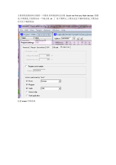
主要讲的是烧录时出现的一个错误.有时烧录时会出现Could not find any flash devices 的错误,不要紧张,只需要改动一个地方就ok了如下图所示,上图为无法下载时的状态,下图为改后可以下载的状态.
注意erase中的内容
只需改动这一处就ok了
以下内容是j-flash 的基本设置,可以参考一下
1.双击此图标打开j-flash
2
file-open project 选择你的芯片型号,我的是stm32103RB.
3
file-open data file 选择需要的程序固件.hex或.bin均可.
4
Options-project setting 进行相关配置.如图即可
5
照图上设置即可
6
照图上设置即可
7
此页默认即可
8
9开始下载了哦, 方便起见,此版本的J-FLASH下载固件时直接按F7即可,其他的下载方式基本是先按connect,再erase最后program即可,不过肯定都有快捷键.
10 下载成功后基本上log菜单栏里是这样的描述.我是说基本上哦
完.。
CCS5.4烧写FLASH教程
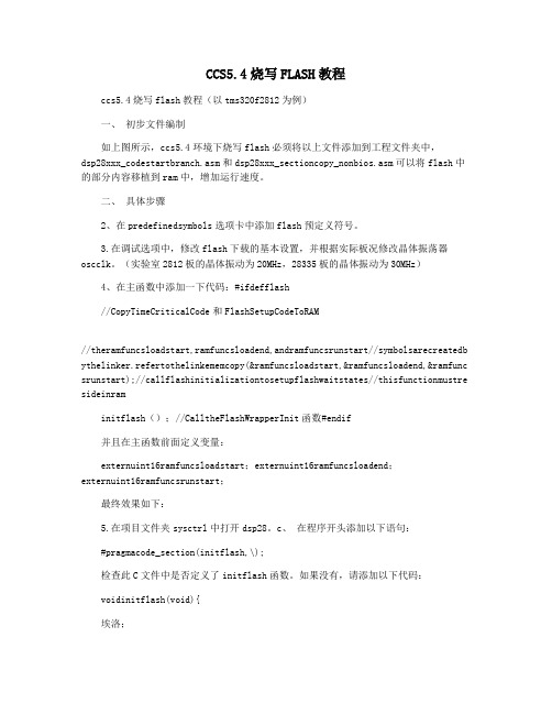
CCS5.4烧写FLASH教程ccs5.4烧写flash教程(以tms320f2812为例)一、初步文件编制如上图所示,ccs5.4环境下烧写flash必须将以上文件添加到工程文件夹中,dsp28xxx_codestartbranch.asm和dsp28xxx_sectioncopy_nonbios.asm可以将flash中的部分内容移植到ram中,增加运行速度。
二、具体步骤2、在predefinedsymbols选项卡中添加flash预定义符号。
3.在调试选项中,修改flash下载的基本设置,并根据实际板况修改晶体振荡器oscclk。
(实验室2812板的晶体振动为20MHz,28335板的晶体振动为30MHz)4、在主函数中添加一下代码:#ifdefflash//CopyTimeCriticalCode和FlashSetupCodeToRAM//theramfuncsloadstart,ramfuncsloadend,andramfuncsrunstart//symbolsarecreatedb ythelinker.refertothelinkememcopy(&ramfuncsloadstart,&ramfuncsloadend,&ramfunc srunstart);//callflashinitializationtosetupflashwaitstates//thisfunctionmustre sideinraminitflash();//CalltheFlashWrapperInit函数#endif并且在主函数前面定义变量:externuint16ramfuncsloadstart;externuint16ramfuncsloadend;externuint16ramfuncsrunstart;最终效果如下:5.在项目文件夹sysctrl中打开dsp28。
ADS下编译程序烧写到FLASH运行
ADS下编译程序烧写到FLASH运行
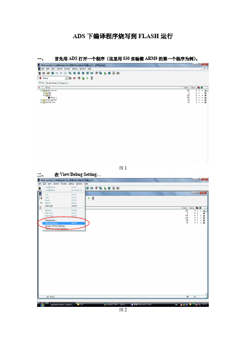
一、首先用ADS打开一个程序(这里用830实验箱ARM9的第一个程序为例)。
图1
二、在View/Debug Setting…
图2
图3
三、在弹出窗口中设置如下:注意打红圈的地方,不要设错!!!设好后点OK!!
图4
图5
图6
图7
图8
图9
图10
四、然后再重新编译
图11
五、在实验程序的工程目录的。
/Debug下就会生成一个。
Bin文件
图12
五、启动超级终端,设置好波特率等参数。
ARM板上电,在终端下快速的按空格键
进入VIVI,如图14。
(注意:在此步之前必须先烧好VIVI,烧写VIVI的方法请参照说明书)
图13
图14
六、在终端下输入命令:load flash kernel x 然后回车如图15,然后在点终端中的传送/发送文件,弹出一个窗口,协议选择Xmodem,然后选择我们编译生成的BIN文件.如图17、18,等到烧写完成后ARM9复位或重新上电,就可以看到程序一上电就运行了。
如图就是本实验的运行结果,在终端打印字符如图21。
图15
图16
图17
图18
图19
图20
图21。
程序烧写方法
3.5寸,红外转发网络烧写使用说明
一、安装软件
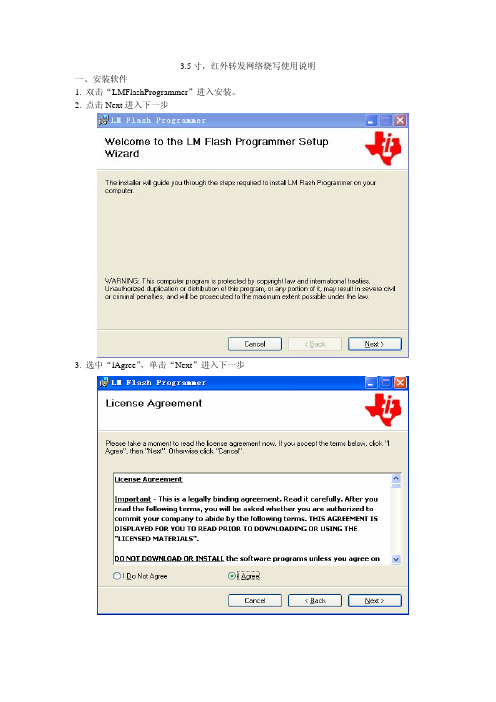
1. 双击“LMFlashProgrammer”进入安装。
2. 点击Next进入下一步
3. 选中“lAgree”,单击“Next”进入下一步
4. 在Folder一栏单击“Browse…”选择程序安装目录后,单击“Next”进入下一步
5. 单击“Next”进入下一步
6. 程序安装中
7. 安装程序完成,单击“Close”退出
二、烧写程序
1. 双击桌面“”图标打开软件
2. 选择“configuration”界面。
2.1. 在“Quick set”一栏复选框里选择“Manual configuration-see below”。
2.2. 在“Interface”一栏复选框里选择“Ethernet”。
2.3. 在“Client IP Address:”后面的框里填上你要烧写的设备的IP地址,如
192.168.0.50。
2.4. “Client MAC Address:”后面的框里填上你要烧写的设备的MAC地址,如
001205071319。
2.5.
3.5寸、红外转发的IP地址与MAC地址都可以通过
获取到。
3. 换到“program”界面
3.1 在“Select.bin file”一栏里,点“browse”选择程序路径。
3.2 单击“Program”烧写
烧写完成后设备会重起。
三、注意事项
1. 设备要与电脑在同一个网段里。
2. 网络烧写时,要用有线连接,不可使用无线连接烧写。
3. 烧写前,3.5寸最好重起一直,重起时不可出现异常现像。
flash烧写说明文档
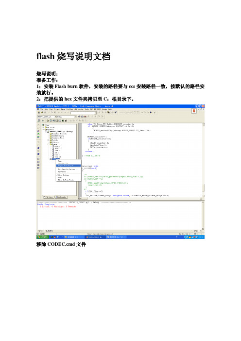
flash烧写说明文档烧写说明:准备工作:1:安装Flash burn软件,安装的路径要与ccs安装路径一致,按默认的路径安装就行。
2:把提供的hex文件夹拷贝至C:根目录下。
移除CODEC.cmd文件project。
在文件类型中选择*.s*依次添加boot_c671x_2.s62,c6713_emif.s62两个文件。
在文件类型中选择*.cmd,添加lnk2.cmd文件。
然后点击Rebuid all按钮重新编译所有文件。
到DEC6713_CODEC.out文件,复制该文件到C:根目录下的hex文件夹下。
双击“命令提示符快捷方式”文件。
后关键命令窗口。
然后复制hex文件至工程文件夹下,C:\ti\myprojects\fft080111endDEC6713_CODEC.pjt工程。
打开TOOL下的FlashBurn工具。
在file中单击new。
在conversion Cmd框中添加hex文件夹下的boot.cmd文件。
在File to burn中添加hex文件夹下的DEC6713_CODEC.hex文件。
在FBTC program file框中添加FBTC6713文件夹下的FBTC6713.out文件。
在flash physical 填写0x90000000 ,bytes 0x40000,然后保存,关闭Flshburn界面。
在file工具栏选择load GEL,加载DEC6713.gel文件。
文件。
如上图说明连接正常。
首先点击Erase Flash选项。
单击program下的proram Flash工具,等待烧写完毕,然后关闭ccs,重新给目标板上电,烧写过程结束。
TMS320C62x HPI引导过程的实现摘要:TMS320C62x和TMS320C67x DSPs提供了几种不同的启动模式,不同的启动模式决定了DSP复位后的初始化以及代码装载方式。
本文就TMS320C62x DSP 的HPI启动模式进行详细的说明。
jlink烧写程序图文教程
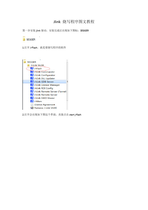
Jlink 烧写程序图文教程第一步安装jlink驱动,安装完成后出现如下图标:SEGGER1.打开J-Flash,就是要烧写程序的软件2.打开会出现如下图这个界面,直接点击start j-flash3.进入后,点击open project,打开工程4.选择你的cpu芯片的对应jflash,下图是对应的NXP的LPC2114这款芯片,D:\Program Files\SEGGER\JLink_V490\Samples\JFlash\ProjectFiles\NXP,这个是路径完成后,会提示成功的标语,下图中我已经选择了下载文件,所以出现了对应的二进制文件,正常情况下到这一步是没有出现2进制文件的,这时需要点击图中的connect,如果出现下面错误,就是提示could not find any flash devices ,这表示连接不成功,解决的办法就是,选择options—project settings ,改变cpu设备点击CPU选项,按图中选择device,找到你对应的cpu就可以了这是提示连接成功的截图。
之后就可以选择你所需要下载的程序文件了,点击file—open data file这边需要注意的是,每次只能打开一个程序文件,比如图中的二进制文件,只能有一个接着就是烧写了,点击target – program如果出现read memory error 错误,有2个选择,1关闭当前要下载的程序,重新选择二进制文件,2,选择target中的program&verify 或者auto,一般情况下auto这个选择都是可以执行的,这个auto一般情况下都是下载成功的,如果到这一步还不成功的话,就选择关闭软件,按上面再来一次,或者重新选择程序,最后一图就是下载成功的提示,一切完成。
SPI Flash 烧写指导书

SPI FLASH 程序烧写指导书
1.相关软件和工具
使用软件SmartPRO注意软件版本更新。
烧写器:SmartPRO 5000U (已验证)
需要烧写成品板卡例:PX2000E-PRO
烧写芯片卡座(ZY301A等)
2.操作指导
2.1将PX2000E-PRO 上的FLASH 存储器(带程序)取下放入烧写
卡座ZY301A,卡座安装在烧写器卡槽最底端。
2.2 打开SmartPRO 软件,选择相关器件型号,得到如下显示框。
如图所示为相关操作界面,可以先简单熟悉一下。
2.3制作烧写文档,读取现有FLASH 中程序。
1.点击工具栏-操作配置,如图所示相关设置。
2.烧写栏中选择烧写器件型号
3.文件读取保存(BIN 文件)
后续相关烧写操作也是在这边进行,可以选择组合操作。
4.量产烧写
设置组合操作:擦除-编程-校验
选择器件型号和烧写文件,组合操作,量产。
3.备注
1.烧写不同芯片时,根据封装大小选择适合的烧写卡座。
2.首次烧写需要读取FLASH(EEPROM)中的数据文件,包括
后期相关程序更新。
flash的烧写
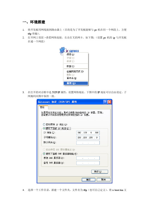
一、环境搭建1.将开发板用网线接到路由器上(目的是为了开发板能够与pc机在同一个网段上,方便tftp传输)。
2.打开网上邻居->查看网络连接,右击打叉的网卡,如下图:(设置pc机的ip与开发板在通一个网段)3.在打开的对话框中选TCP/IP属性,设置网络地址。
下图中的IP地址可以自由设定,子网掩码同图中保持一致。
4.选择一个工作目录,新建一个文件夹,文件名为tftp(也可自己定义),将u-boot.bin文件、zImage文件等,拷贝到该目录。
5.解压tftpd32.400.zip,打开tftpd32.exe软件,设置文件夹位置和IP地址,如下图所示:6.将开发板用串口同PC串口相连,打开SecureCRT,新建一个串口连接,连接的设置如下:7.开发板接上电源,打开电源开关,在串口终端中可以看到以下内容:二、制作镜像文件(制作版本)1、进入ipc的后台执行如下命令:生成u-boot.bin:cat /dev/mtdblock0 > u-boot.bin生成uImage:cat /dev/mtdblock1 > uImage生成rootfs.img:cat /dev/mtdblock2 > rootfs.img生成config.bin:cat /dev/mtdblock3 > config.bin上面的命令要正确的执行首先得确保分区是存在的,而且分区里面都已烧写了对应的文件。
分区的创建:(参考)Creating 5 MTD partitions on "hi_sfc":mtdbloc0 0x000000000000-0x000000100000 : "boot"mtdbloc1 0x000000100000-0x0000003e0000 : "kernel"mtdbloc2 0x0000003e0000-0x000000dc0000 : "rootfs"mtdbloc3 0x000000dc0000-0x000000f00000 : "config"mtdbloc4 0x000000f00000-0x000000f10000 : "key"三、进入u_boot烧写nand flash1、启动ipc,在u_boot启动完成后,按任意键进入u_boot命令模式。
FLASH烧写的步骤

FLASH烧写的步骤大概如下
1、安装FLASH插件,CCS3.1版本的对应的插件版本(FLASH2X
for CCS3.1.EXE)要在1.12以上,否则不能烧写FLASH,安装完毕后,在CCS3.1的TOOLS工具中多一条F28XX on ship flash programmer。
2、将FLASH.CMD文件代替SRAM.CMD文件,编译程序后生成
“xx.OUT”文件。
3、点击TOOLS->F28XX on ship flash programmer,点击版面上的
“flash programmer Settings”后弹出一个对话框,点击BROWSE 按钮,选择弹出对话框中的文件:“FlashAPIInterface2812V2_10.out”,接着点击“OK”按钮。
注意改版面不要轻易修改任何参数,否则会造成DSP芯片死锁报废!不需要设时钟或者空间!!!
4、返回上一层界面后点击“Execute Operation”,DSP开始擦写
FLASH,在擦写过程中,禁止碰动DSP板子,防止出现烧写问题。
烧写完成后信息栏出现:
Erase/Program/V erify Operation succeeded
**** End Erase/Program/V erify Operation. ***
Device reset detected. Updating locked or unlocked
state of target in Flash Programmer.
The device is unlocked.
大功告成。
arm烧写Flash过程

⏹程序调试结束,要将其可执行文件烧写(或称固化)到目标机中Flash运行,这个过程要通过一个转门的下载软件来进行,以Embest OnLine Flash Programmer for ARM为例,来说明该软件的安装和使用。
⏹ 1. 安装Flash Programmer⏹Flash Programmer安装过程比较简单,运行Flash Programmer安装包中的Setup.exe,按照提示一步步执行即可。
⏹Flash Programmer安装程序将自动区分电脑是否已安装Embest IDE软件的情况:⏹①电脑已安装Embest IDE软件,安装程序将会把Flash Programmer缺省安装到“Embest IDE安装目录\Tools\FlashProgrammer”目录,见图2-24。
同时安装程序将自动探测是否安装与IDE软件共享的设备模块和驱动程序,安装完毕后电脑无需重新启动。
如果IDE已注册,软件可直接运行。
⏹②电脑未安装Embest IDE软件,安装程序将会把Flash Programmer缺省安装到“Program Files\Embest\FlashProgrammer”目录,安装完毕后需要重新启动。
软件正常运行时需要注册。
软件安装完成后将缺省建立Embest Tools 程序文件夹,包含执行程序和帮助的快捷方式。
2. Flash Programmer的功能⏹点击Flash Programmer图标,出现图2-25对话框,在第一行有四个一级菜单,下面分别介绍。
⏹①文件菜单⏹文件菜单用于保存、打开用户设置的编程配置数据文件,该文件一般以*.cfg形式存在。
通过文件菜单,用户还可以将已打开的编程配置数据文件里另存为其他文件,以及打开最近打开过的四个编程配置文件。
文件菜单各子菜单命令如表2-1所示。
⏹表2-1 文件菜单⏹图2-25 Flash Programmer对话框⏹②设置菜单⏹设置菜单仅包含Configure子菜单。
东芝FLASH编程器使用说明

一、烧录工具上海耕研东芝单片机烧写器(USB)一台PC电脑一台电源适配器(9V/1.5A)一个USB连接线一条二、烧录软件版本信息GTPRO 1.33版三、适用单片机四、调试过程1、确认防静电手环接地良好后,戴上防静电手环。
2、根据单片机型号选好烧写器,不同单片机烧写器不一样,但烧录软件一样。
3、将烧录器接上AC/DC Adaptor(输出:DC9V,1.5A),接上USB转接线,打开开关到ON位置,绿色指示灯L1点亮,启动PC电脑.4、打开桌面上的快捷方式GTPRO1.33,如下图5、点击“选择”图标,双击“MCU”,再双击“FLASH”,依不同的单片机选择对应型号后确定。
会出现“芯片选择正确,请重新运行程序”的提示。
6、重复第4步。
应出现下述设置好的信息。
7、点击“打开”图标,出现“填充选择”窗口,选“FF”后“OK”。
8、加载要烧录的文件,选中后,点击“打开”。
下图只是范例,具体项目有别:9、在信息窗口查看相关信息,重点核对校验和是否与《芯片拷贝申请记录表》一致。
10、点击“下载”,提示“下载成功”后,点击“确认”。
11、点击“上传”,提示“上传成功”后,点击“确认”。
查看上传成功后信息栏的校验和是否一致。
12、若“上传的数据”对应的校验和与第(9)步打开*.H16文件所对应的校验和一致,则可进行脱机烧录(断开与PC机的连接,只给烧录器提供电源)。
五、脱机烧录:1.烧写器产品外观及按键功能,指示灯说明:2. 烧录操作步聚:a. 将电源开关打到“ON ”位置,L1亮绿色;b. 将待烧录芯片放于适配器座上,芯片缺口朝上放置,并拉下锁紧拉杆;c. 按下编程按钮,L1、L2显示红色,为烧录状态;d. 烧录完成后,L1回复绿色,L3显示绿色,烧录成功。
如L3显示红色,则烧录错误,此时,需重复第C 步骤,重新烧录;e. 将烧录正确的芯片取下,在其上方打点做标记,并放入IC 管内;f. 重复c-e 步聚,开始下一轮烧录。
- 1、下载文档前请自行甄别文档内容的完整性,平台不提供额外的编辑、内容补充、找答案等附加服务。
- 2、"仅部分预览"的文档,不可在线预览部分如存在完整性等问题,可反馈申请退款(可完整预览的文档不适用该条件!)。
- 3、如文档侵犯您的权益,请联系客服反馈,我们会尽快为您处理(人工客服工作时间:9:00-18:30)。
Application ReportSPRA958F – January 2006 Running an Application from Internal Flash Memory onthe TMS320F28xx DSP David M. Alter DSP Applications - Semiconductor Groupduring development in RAM since the Code Composer Studio™ debugger can maskproblems associated with initialized sections and how they are linked to memory. Thisapplication report covers the requirements needed to properly configure applicationsoftware for execution from on-chip flash memory. Requirements for both DSP/BIOS™and non-DSP/BIOS projects are presented. Some performance considerations andtechniques are also discussed. Example code projects are included that run from on-chipflash on the eZdsp™ F2812 and eZdsp F2808 development boards (or alternately, anyF2801, F2806, F2808, F2810, F2811, or F2812 DSP board). Code examples that runfrom internal RAM are also provided for completeness. These code examples provide astarting point for code development, if desired.Note that the issues discussed in this application report apply directly to current F281xand F280x members of the TMS320F28xx DSP family, specifically the F2801, F2806,F2808, F2810, F2811, and F2812 DSP devices. Applicability to future devices in theF28xx family, although quite likely, is not guaranteed. In addition, the code andtechniques presented in this application report for DSP/BIOS projects was developed onCode Composer Studio v3.1 using C-compiler v4.1.1 and DSP/BIOS v5.20. Earlierversions of DSP/BIOS used a different configuration file format. It is suggested that thereader upgrade to the latest version. Future versions of DSP/BIOS may have differencesthat make some of the items discussed in this report unnecessary (although in alllikelihood backwards compatibility will be maintained, so that the techniques discussedhere should still work). The reader should keep this in mind if using a newer version.Finally, this application report does not provide a tutorial on writing and building code forthe F28xx DSP. It is assumed that the reader already has at least the main framework oftheir application code running from RAM, probably using the Code Composer Studiodebugger to perform the code download. This report only identifies the special items thatmust be considered when moving the application into on-chip flash memory.Code Composer Studio and DSP/BIOS are trademarks of Texas Instruments.eZdsp is a trademark of Spectrum Digital Incorporated.Trademarks are the property of their respective owners.1SPRA958FContents1Introduction (3)2Creating a User Linker Command File (3)2.1Non-DSP/BIOS Projects (3)2.2DSP/BIOS Projects (4)3Where to Link the Sections (5)3.1Non-DSP/BIOS Projects (5)3.2DSP/BIOS Projects (7)4Copying Sections from Flash to RAM (9)4.1Copying the Interrupt Vectors (non-DSP/BIOS projects only) (9)4.2Copying the .hwi_vec Section (DSP/BIOS projects only) (10)4.3Copying the .trcdata Section (DSP/BIOS projects only) (10)4.4Initializing the Flash Control Registers (DSP/BIOS and non-DSP/BIOS projects) (12)4.5Maximizing Performance by Executing Time-critical Functions from RAM (14)4.6Maximizing Performance by Linking Critical Global Constants to RAM (15)4.6.1Method 1: Running All Constant Arrays from RAM (15)4.6.2Method 2: Running a Specific Constant Array from RAM (18)5Programming the Code Security Module Passwords (19)6Executing Your Code from Flash after a DSP Reset (23)7Disabling the Watchdog Timer During C-Environment Boot (25)8C-Code Examples (27)8.1General Overview (27)8.2Directory Structure and File Utilizations (28)8.3Additional Information (33)References (35)Revision History (36)FiguresFigure 1.Specifying the User Init Function in the DSP/BIOS Configuration tool (11)Figure 2.Specifying the Link Order In Code Composer Studio (17)Figure 3.DSP/BIOS MEM Properties for CSM Password Locations (22)Figure 4.DSP/BIOS MEM Properties for CSM Reserved Locations (22)Figure 5.DSP/BIOS MEM Properties for Jump to Flash Entry Point (24)TablesTable 1.Section Linking in Non-DSP/BIOS Projects (Large memory model) (6)Table 2.Section Linking In DSP/BIOS Projects (Large Memory Model) (7)Table 3.Example Code File Directories (28)Table 4.F281x Example Code File Inventory and Utilization (29)Table 5.F280x Example Code File Inventory and Utilization (31)2Running an Application from Internal Flash Memory on the TMS320F28xx DSPSPRA958F1 IntroductionThe TMS320F28xx DSP family has been designed for standalone operation in embeddedcontroller applications. The on-chip flash usually eliminates the need for external non-volatilememory and a host processor from which to bootload. Configuring an application to run fromflash memory is a relatively easy matter provided that one follow a few simple steps. This report covers the major concerns and steps needed to properly configure application software forexecution from internal flash memory. Requirements for both DSP/BIOS and non-DSP/BIOSprojects are presented. Some performance considerations and techniques are also discussed.Note that the issues discussed in this application report apply directly to current F281x andF280x members of the TMS320F28xx DSP family. Throughout the remainder of this report, the term current F28xx devices will refer specifically to the F2801, F2806, F2808, F2810, F2811,and F2812 DSP devices. Applicability to future devices in the F28xx family, although quitelikely, is not guaranteed. In addition, the code and techniques presented in this applicationreport for DSP/BIOS projects was developed on Code Composer Studio v3.1 using C-compiler v4.1.1 and DSP/BIOS v5.20. Earlier versions of DSP/BIOS used a different configuration fileformat. It is suggested that the reader upgrade to the latest version. Future versions ofDSP/BIOS may have differences that make some of the items discussed in this reportunnecessary (although in all likelihood backwards compatibility will be maintained, so that thetechniques discussed here should still work). The reader should keep this in mind if using anewer version.Finally, this application report does not provide a tutorial on writing and building code for theF28xx DSP. It is assumed that the reader already has at least the main framework of theirapplication code running from RAM, probably using the Code Composer Studio debugger toperform the code download. This report only identifies the special items that must beconsidered when moving the application into on-chip flash memory.2 Creating a User Linker Command File2.1 Non-DSP/BIOS ProjectsIn non-DSP/BIOS applications, the user linker command file will be where most memory isdefined, and where the linking of most sections is specified. The format of this file is no different than the linker command file you are currently using to run your application from RAM. Thedifference will be in where you link the sections (to be discussed in Section 3). More information accompany this application report contain linker command files that can be used for reference.Running an Application from Internal Flash Memory on the TMS320F28xx DSP 3SPRA958FThe DSP281x and DSP280x peripheral header files contain linker command files namedDSP281x_Headers_nonBIOS.cmd and DSP280x_Headers_nonBIOS.cmd, respectively (see references [10] and [11]). These files contains linker MEMORY and SECTIONS declarations for linking the peripheral register structures. Since Code Composer Studio supports having more than one linker command file in a project, all one needs to do is add the header file linkercommand file to their project in addition to their user linker command file. In general, the order of the linker command files is unimportant since during a project build, Code Composer Studio evaluates the MEMORY section of every linker command file before evaluating the SECTIONS section of any linker command file. This ensures that all memories are defined before linking any sections to those memories. However, advanced users may need manual control over the order of linker command file evaluation in some rare situations. This can be specified withinCode Composer Studio on the Project → Build_Options, Link_Order tab.2.2 DSP/BIOS ProjectsThe DSP/BIOS configuration tool generates a linker command file that specifies how to link all DSP/BIOS generated sections, and by default all C-compiler generated sections. When running your application from RAM, this linker command file may be the only one in use. However,when executing from flash memory, there will likely be a need to generate and link one or more user defined sections. In particular, any code that configures the on-chip flash control registers(e.g. flash wait-states) cannot execute from flash. In addition, one may want to run certain timecritical functions from RAM (instead of flash) to maximize performance. A user linker command file must be created to handle these user defined sections.Code Composer Studio supports having more than one linker command file in a project. Hence, all one needs to do is add both the user linker command file, as well as the DSP/BIOSgenerated linker command file, to their project. In general, the order of the linker command files is unimportant since during a project build, Code Composer Studio evaluates the MEMORYsection of every linker command file before evaluating the SECTIONS section of any linkercommand file. This ensures that all memories are defined before linking any sections to those memories. However, advanced users may need manual control over the order of linkercommand file evaluation in some rare situations (for example, to preempt and overrideDSP/BIOS linkage of a section). This can be specified within Code Composer Studio on the Project → Build_Options, Link_Order tab.The DSP281x and DSP280x peripheral header files contain linker command files namedDSP281x_Headers_nonBIOS.cmd and DSP280x_Headers_nonBIOS.cmd, respectively (see references [10] and [11). These file contains linker MEMORY and SECTIONS declarations for linking the peripheral register structures. Simply add the appropriate one of these linkercommand files to your code project as well.4Running an Application from Internal Flash Memory on the TMS320F28xx DSPSPRA958FRunning an Application from Internal Flash Memory on the TMS320F28xx DSP 53 Where to Link the SectionsTwo basic section types exist: initialized, and uninitialized. Initialized sections must contain valid values at device power-up. For example, code and constants are found in initialized sections. When designing a stand-alone embedded system with the F28xx DSP (e.g., no emulator or debugger in use, no host processor present to perform bootloading), all initialized sections must be linked to non-volatile memory (e.g., on-chip flash). An uninitialized section does not contain valid values at device power-up. For example, variables are found in uninitialized sections. Code will write values to the variable locations during code execution. Therefore, uninitialized sections must be linked to volatile memory (e.g., RAM).It is suggested that the -w linker option be invoked. The -w option will produce a warning if thelinker encounters any sections in your project that have not been explicitly specified for linking in a linker command file. When the linker encounters an unspecified section, it uses a default allocation algorithm to link the section into memory (it will link the section to the first defined memory with enough available free space). This is almost always risky, and can lead tounreliable and unpredictable code behavior. The -w option will identify any unspecified sections (e.g., those accidentally forgotten by the user) so that the user can make the necessary addition to the appropriate linker command file. The -w option can be selected in Code Composer Studio on the Project → Build_Options menu, Linker tab, select the Advanced category, and then check the -w option box. It is checked by default for new projects. addressable space. However, no flash memory is present in this region on anycurrent F28xx devices, and this will likely be true for future F28xx devices as well. Therefore, large memory model should be used. In Code Composer project. 3.1 Non-DSP/BIOS ProjectsThe compiler uses a number of specific sections. These sections are the same whether you are running from RAM or flash. However, when running a program from flash, all initialized sections must be linked to non-volatile memory, whereas all uninitialized sections must be linked to volatile memory. Table 1 shows where to link each compiler generated section on the F28xx DSP. Information on the function of each section can be found in reference [3]. Any user created initialized section should be linked to flash (e.g., those sections created using theCODE_SECTION compiler pragma), whereas any user created uninitialized sections should be linked to RAM (e.g., those sections created using the DATA_SECTION compiler pragma).SPRA958F6 Running an Application from Internal Flash Memory on the TMS320F28xx DSPTable 1. Section Linking in Non-DSP/BIOS Projects (Large memory model) Section Name Where to Link.cinit Flash .cio RAM .const Flash .econst Flash.pinit Flash.switch Flash.text Flash.bss RAM.ebss RAM.stack Lower 64Kw RAM.sysmem RAM.esysmem RAM.reset RAM 1Table 1 Notes:1The .reset section contains nothing more than a 32-bit interrupt vector that points to theC-compiler boot function in the runtime support library (the _c_int00 routine). It generally is not used. Instead, the user typically creates their own branch instruction to point to the starting point of the code (see Sections 6 and 7). When not in use, the .reset section should be omitted from the code build by using a DSECT modifier in the linker command file. For example:/******************************************************************** * User's linker command file********************************************************************/SECTIONS{.reset : > FLASH, PAGE = 0, TYPE = DSECT}SPRA958FRunning an Application from Internal Flash Memory on the TMS320F28xx DSP 7SPRA958F 4 Copying Sections from Flash to RAM4.1 Copying the Interrupt Vectors (non-DSP/BIOS projects only)Running an Application from Internal Flash Memory on the TMS320F28xx DSP 910Running an Application from Internal Flash Memory on the TMS320F28xx DSPFigure 1. Specifying the User Init Function in the DSP/BIOS Configuration toolWhat remains is to create the user initialization function. The DSP/BIOS configuration toolgenerates global symbols that can be accessed by code in order to determine the load address, run address, and length of each section. These symbol names are:trcdata_loadstarttrcdata_loadend trcdata_runstartEach symbol is self-explanatory from its name. Note that the symbols are not pointers, butrather symbolically reference the 16-bit data value found at the corresponding location (i.e., start or end) of the section. The C-compiler runtime support library contains a memory copy function called memcpy() that can be used to perform the copy task. A C-code example of a user init function that performs the .trcdata section copy follows.leadingunderscore)4.4secured RAM (e.g., L0 or L1 SARAM) or the initialization code will be unable toalthough the ROM bootloader will unlock it if you are using dummy passwordsof 0xFFFF.The CODE_SECTION pragma of the C compiler can be used to create a separately linkable section for the flash initialization function. For example, suppose the flash register configuration is to be performed in the C function InitFlash(), and it is desired to place this function into alinkable section called secureRamFuncs. The following C-code example shows proper use of the CODE_SECTION pragma along with an example configuration of the flash registers:/********************************************************************* User's C-source file********************************************************************//********************************************************************* NOTE: The InitFlash() function shown here is just an example of an* initialization for the flash control registers. Consult the device* datasheet for production wait state values and any other relevant* information. Wait-states shown here are specific to current F280x* devices operating at 100 MHz.* Also, this function assumes use of the DSP281x or DSP280x Header* File structures (TI Literature #SPRC097 and #SPRC191).********************************************************************/#pragma CODE_SECTION(InitFlash, "secureRamFuncs")void InitFlash(void){asm(" EALLOW"); // Enable EALLOW protected register access FlashRegs.FPWR.bit.PWR = 3; // Flash set to active modeFlashRegs.FSTATUS.bit.V3STAT = 1; // Clear the 3VSTAT bitFlashRegs.FSTDBYWAIT.bit.STDBYWAIT = 0x01FF; // Sleep to standby cyclesFlashRegs.FACTIVEWAIT.bit.ACTIVEWAIT = 0x01FF; // Standby to active cyclesFlashRegs.FBANKWAIT.bit.RANDWAIT = 3; // F280x Random access wait states FlashRegs.FBANKWAIT.bit.PAGEWAIT = 3; // F280x Paged access wait states FlashRegs.FOTPWAIT.bit.OTPWAIT = 5; // F280x OTP wait statesFlashRegs.FOPT.bit.ENPIPE = 1; // Enable the flash pipelineasm(" EDIS"); // Disable EALLOW protected register access/*** Force a complete pipeline flush to ensure that the write to the last registerconfigured occurs before returning. Safest thing is to wait 8 full cycles. ***/ asm(" RPT #6 || NOP");} //end of InitFlash()The section secureRamFuncs can then be linked using the user linker command file. This section will require separate load and run addresses. Further, we will want to have the linker generate some global symbols that can be used to determine the load address, run address,and length of the section. This information is needed to perform the copy from the sections load address to its run address. The user linker command file would appear as follows:/********************************************************************* User's linker command file********************************************************************/SECTIONS{/*** User Defined Sections ***/secureRamFuncs: LOAD = FLASH, PAGE = 0RUN = SECURE_RAM, PAGE = 0RUN_START(_secureRamFuncs_runstart),LOAD_START(_secureRamFuncs_loadstart),LOAD_END(_secureRamFuncs_loadend)}In this example, the memories FLASH and SECURE_RAM are assumed to have been defined either in the MEMORY section of the user linker command file (for non-DSP/BIOS projects) or in the memory section manager of the DSP/BIOS configuration tool (for DSP/BIOS projects). The PAGE designation for these memories should match that of the memory definition. The above example assumes both memories have been declared on PAGE 0 (program memory space).The RUN_START, LOAD_START, and LOAD_END directives will generate global symbols with the specified names for the corresponding addresses. Note the use of the leading underscore on the global symbol definitions (e.g.,Finally, the section must be copied from flash to RAM at runtime. As in Sections 4.1 - 4.3, the function memcpy() from the compiler runtime support library can be used:/********************************************************************* User's C-source file********************************************************************/#include <string.h>extern unsigned int secureRamFuncs_loadstart;extern unsigned int secureRamFuncs_loadend;extern unsigned int secureRamFuncs_runstart;void main(void){/* Copy the secureRamFuncs section */memcpy(&secureRamFuncs_runstart,&secureRamFuncs_loadstart,&secureRamFuncs_loadend - &secureRamFuncs_loadstart);/* Initialize the on-chip flash registers */InitFlash();}4.5 Maximizing Performance by Executing Time-critical Functions from RAM(DSP/BIOS and non-DSP/BIOS projects)The on-chip RAM memory on current F28xx devices provides code execution performance of 150 MIPS (millions of instructions per second) at 150 MHz on F281x devices, and 100 MIPS at 100 MHz on F280x devices. However, the on-chip flash memory on these devices provideseffective code execution performance that is slightly less: roughly 90 – 100 MIPS on F281xdevices, and roughly 85 – 90 MIPS on F280x devices. It may therefore be desirable to runcertain time-critical or computationally demanding routines from on-chip RAM. However, in a standalone embedded system, all code must initially reside in non-volatile memory. Therefore, separate load and run addresses must be setup for those functions running from RAM, and a copy must be performed to move them from the on-chip flash to the RAM at runtime. To do this, apply the same procedure previously described in Section 4.4.Using the CODE_SECTION pragma, one can add multiple functions to the same linkablesection. The entire section can then be assigned to run from a particular RAM block, and the user can copy the entire section to RAM all at once, as discussed in Section 4.4. If finer linking granularity is required, separate section names can be created for each function.4.6 Maximizing Performance by Linking Critical Global Constants to RAM(DSP/BIOS and non-DSP/BIOS projects)Constants are those data structures declared using the C language const type modifier. The compiler places all constants in the .econst section (large memory model assumed). Whilespecial pipelining on current F28xx devices accelerates effective flash performance for codeexecution, accessing data constants located in the on-chip FLASH can take multiple cycles per access. Typical flash wait-states will be 5 cycles on a 150 MHz F281x DSP, and 3 cycles on a 100 MHz F280x DSP (see the device datasheet for flash wait-state specifications). It maytherefore be desirable to keep heavily accessed constants and constant tables in on-chip RAM.However, a standalone embedded system requires that all initialized data (e.g., constants)initially reside in non-volatile memory. Therefore, separate load and run addresses must besetup for those constants you wish to access in RAM, and a copy must be performed to move them from the on-chip flash to the RAM at runtime. Two different approaches for accomplishing this will be presented.4.6.1 Method 1: Running All Constant Arrays from RAMThis approach involves specifying separate load and run addresses for the entire .econstsection. The advantage of this approach is ease of use, while the disadvantage is excessive RAM usage (there may be only a few constants that require high-speed access, but with this method all constants are relocated into RAM).4.6.1.1 Non-DSP/BIOS ProjectsThe same approach discussed in Section 4.4 can be used. Simply specify separate load and run address for the .econst section in the user linker command file, and then add code to your project to copy the entire .econst section to RAM at runtime. For example:/********************************************************************* User's linker command file********************************************************************/SECTIONS{.econst: LOAD = FLASH, PAGE = 0RUN = RAM, PAGE = 1RUN_START(_econst_runstart),LOAD_START(_econst_loadstart),LOAD_END(_econst_loadend)}/********************************************************************* User's C-source file********************************************************************/#include <string.h>extern unsigned int econst_loadstart;extern unsigned int econst_loadend;extern unsigned int econst_runstart;void main(void){/* Copy the .econst section */memcpy(&econst_runstart,&econst_loadstart,&econst_loadend - &econst_loadstart);}an example of this, where f2808_BIOS_flash.cmd is the name of the user linker command file, and example_BIOS_flashcfg.cmd is the name of the DSP/BIOS generated linker command file.Figure 2. Specifying the Link Order In Code Composer StudioNote that since the DSP/BIOS generated linker command file will also attempt to link the .econst section, the linker will give a warning stating "Multiple definitions of SECTION named '.econst'." This warning can be safely ignored.The .econst section can then be copied from its load address to its run address as follows:4.6.2 Method 2: Running a Specific Constant Array from RAM(DSP/BIOS and non-DSP/BIOS projects)This method involves selectively copying constants from flash to RAM at runtime. Theprocedure to accomplish this is similar to that of Method 1, except that only selected constants are placed in a named section and copied to RAM (rather than copying all constants to RAM).Suppose for example that one wants to create a 5 word constant array called table[ ] to be run from RAM. A DATA_SECTION pragmas used to place table[ ] in a user defined section called ramconsts. The C-source file would appear as follows:/********************************************************************* User's C-source file********************************************************************/#pragma DATA_SECTION(table, "ramconsts")const int table[5] = {1,2,3,4,5};void main(void){}The section ramconsts is linked to load to flash but run from RAM using the user linkercommand file, and global symbols are generated to facilitate the memory copy. The user linker command file would appear as follows:/********************************************************************* User's linker command file********************************************************************/SECTIONS{/*** User Defined Sections ***/ramconsts: LOAD = FLASH, PAGE = 0RUN = RAM, PAGE = 1LOAD_START(_ramconsts_loadstart),LOAD_END(_ramconsts_loadend),RUN_START(_ramconsts_runstart)}Finally, table[ ] must be copied from its load address to its run address at runtime:/********************************************************************* User's C-source file********************************************************************/#include <string.h>extern unsigned int ramconsts_loadstart;extern unsigned int ramconsts_loadend;extern unsigned int ramconsts_runstart;void main(void){/* Initialize the ramconsts section */memcpy(&ramconsts_runstart,&ramconsts_loadstart,&ramconsts_loadend - &ramconsts_loadstart);}5 Programming the Code Security Module Passwords(DSP/BIOS and non-DSP/BIOS projects)The CSM module on F28xx devices provides protection against unwanted copying of yoursoftware. On current F28xx devices, the entire flash, the OTP memory, and the L0 and L1 RAM blocks are secured by the CSM (the flash configuration registers are secured as well). When secured, only code executing from secured memory can access data (read or write) in othersecured memory. Code executing from unsecured memory cannot access data in securedmemory. Detailed information on the CSM module can be found in references [4] and [5].The CSM uses a 128-bit password comprised of 8 individual 16-bit words. On current F28xx devices, these passwords are stored in the upper most 8 words of the flash (i.e., addresses0x3F7FF8 to 0x3F7FFF). During development, it is recommended that dummy passwords of0xFFFF be left in the password locations. When dummy passwords are used, only dummy reads of the password locations are needed to unsecure the CSM. Placing dummy passwords into the password locations is easy to do since 0xFFFF will be the state of these locations after the flash is erased during flash programming. Users need only avoid linking any sections to the password addresses in their code project, and the passwords will retain the 0xFFFF.After development, one may want to place real passwords in the password locations. In addition, the CSM module on current F28xx devices requires programming values of 0x0000 into flash addresses 0x3F7F80 through 0x3F7FF5, inclusive, in order to properly secure the CSM (see references [1] and [2]). The easiest way to accomplish both of these tasks is with a little simple assembly language programming. The following is an example of an assembly code file that specifies the desired password values, and places them in a named initialized section called passwords. It also creates a named initialized section called csm_rsvd that contains all0x0000 values and is of proper length to fit in addresses 0x3F7F80 to 0x3F7FF5, inclusive. See reference [6] for more information on the assembly language directives used.************************************************************************ File: passwords.asm*********************************************************************************************************************************************** Dummy passwords of 0xFFFF are shown. The user can change these to* desired values.** CAUTION: Do not use 0x0000 for all 8 passwords or the CSM module will* be permanently locked. See the "TMS320x281x System Control and* Interrupts Peripheral Reference Guide" (SPRU078) or the "TMS320x280x* System Control and Interrupts Peripheral Reference Guide" (SPRU712)* for more information.***********************************************************************.sect "passwords".int 0xFFFF ;PWL0 (LSW of 128-bit password).int 0xFFFF ;PWL1.int 0xFFFF ;PWL2.int 0xFFFF ;PWL3.int 0xFFFF ;PWL4.int 0xFFFF ;PWL5.int 0xFFFF ;PWL6.int 0xFFFF ;PWL7 (MSW of 128-bit password);----------------------------------------------------------------------.sect "csm_rsvd".loop (3F7FF5h - 3F7F80h + 1).int 0x0000.endloop;----------------------------------------------------------------------.end ;end of file passwords.asmNote that this example is showing dummy password values of 0xFFFF. Replace these values with your desired passwords.。
