KCDC03-106中文资料
OC-3中文资料

OC-3中⽂资料Headquarters :No. 669, Sec. 4 Chung Hsing RoadFeaturesCompliant with 155 Mbps ATM and SONET OC-3SDH STM-1 (S1.1) Industry standard 1×9 footprint SC duplex connector Single power supply 3.3 VDifferential LVPECL inputs and outputsCompatible with solder and aqueous wash processes Class 1 laser product complies with EN 60825-1 DescriptionThe TS3-0155-32S-P1-X transceivers utilizing 1310 nm MQW laser diodes are fully compliance to the 155 Mbps ATM and SONET OC-3 SDH STM-1 standard, anddesigned in industry standard 1×9 package with SC duplex connector. The transmitter section is a class 1 laser which is compliant to International Safety Standard EN 60825-1.Ordering InformationPART NUMBER INPUT/OUTPUTSIGNAL DETECTVOLTAGE TEMPERATURE TS3-0155-32S-P1 DC/DC LVPECL 3.3 V 0°C to 70 °C TS3-0155-32S-P1-E DC/DC LVPECL3.3 V40°C to 85°CAbsolute Maximum RatingsPARAMETER SYMBOL MIN MAX UNITS NOTEStorage Temperature T S ?40 85°CSupply V oltage Vcc ?0.5 6.0 V Input V oltage V IN ?0.5Vcc VOutput Current I o --- 50 mA Operating Current I OP --- 400 mA Soldering Temperature T SOLD--- 260 °C10 seconds on leadsHeadquarters :No. 669, Sec. 4 Chung Hsing RoadOperating EnvironmentPARAMETER SYMBOL MIN MAX UNITS NOTEAmbient Operating Temperature(TS3-0155-32S-P1)T AMB 0 70°C Ambient Operating Temperature (TS3-0155-32S-P1-E) T AMB ?40 85°CSupply V oltageVcc3.1 3.5 VTransmitter Electro-optical Characteristics(Vcc = 3.1 V to 3.5 V , TS3-0155-32S-P1: T A = 0°C to 70°C, TS3-0155-32S-P1-E: T A = ?40°C to 85°C)PARAMETER SYMBOL MIN TYP . MAX UNITS NOTEData RateB 50 155 200 Mb/sOutput Optical Power 9/125 µm fiber Pout ?15---8dBm AverageExtinction Ratio ER8.2 --- --- dB Center Wavelength λC 1261 1310 1360 nm Spectral Width (RMS) ?λ --- --- 4 nm Rise/Fall Time (10?90%) T r , f --- 1 2 nsOutput EyeCompliant with Telcordia GR-253-CORE Issue 3 and ITU-T recommendation G-957Power Supply Current I CC --- --- 140 mA Note 1 Data Input Current-Low I IL ?350--- --- µAData Input Current-HighI IH --- --- 350 µATransmitter Data Input V oltage-High V IH ? V CC ?1.1 --- ?0.74 V Note 2 Transmitter Data Input V oltage-LowV IL ? V CC2.0---1.58V Note 2Transmitter Data Input DifferentialV oltage V DIFF 0.3 --- 1.6 VNote 2Note 1: Not including the terminations.Note 2: These inputs are compatible with 10K, 10KH and 100K ECL and PECL input.Headquarters :No. 669, Sec. 4 Chung Hsing RoadReceiver Electro-optical Characteristics(Vcc = 3.1 V to 3.5 V , TS3-0155-32S-P1: T A = 0°C to 70°C, TS3-0155-32S-P1-E: T A = ?40°C to 85°C)PARAMETER SYMBOLMIN TYP . MAX UNITS NOTE Data RateB 50 155 200 Mb/sOptical Input Power-maximum P IN 0 --- --- dBm Note 1 Optical Input Power-minimum (Sensitivity)P IN--- --- ?34dBm Note 1Operating Center Wavelength λC 1100 --- 1600 nmSignal Detect-Asserted P A --- --- ?34 dBm AverageSignal Detect-Deasserted P D ?47--- --- dBm AverageSignal Detect-Hysteresis P A ? P D 1.0 --- --- dB Signal Detect Assert Time T SD + --- --- 100 µs Signal Detect Desssert Time T SD ? --- --- 100 µsSignal Detect Output voltage-High V OH ? V CC ?1.1 --- ?0.74 V Note 2 Signal Detect Output voltage-Low V OL ? V CC2.0---1.58V Note 2Power Supply CurrentI CC --- --- 100 mA Note 3 Data Output Rise, Fall Time (10?90%) T r, f --- 1 2 nsData Output V oltage-High V OH ? V CC ?1.1 --- ?0.74 V Note 2 Data Output V oltage-LowV OL ? V CC2.0---1.58V Note 2Note 1: The input data is at 155.52 Mbps, 223?1 PRBS data pattern with 72 “1”s and 72 “0”s inserted per the ITU-T recommendation G .958 Appendix 1. The receiver is guaranteed to provide output data with Bit Error Rate (BER) better than or equal to 1×10?10.Note 2: These outputs are compatible with 10K, 10KH and 100K ECL and PECL input. Note 3: The current exclude the output load current.Headquarters :No. 669, Sec. 4 Chung Hsing RoadTransmitter SectionThe transmitter section consists of a 1310 nm InGaAsP laser in an eye safe optical subassembly (OSA) which mates to the fiber cable. The laser OSA is driven by a LD driver IC which converts differential input LVPECL logic signals into an analog laser driving current. Receiver SectionThe receiver utilizes an InGaAs PIN photodiode mounted together with a trans-impedance preamplifier IC in an OSA. This OSA is connected to a circuit providing post-amplification quantization, and optical signal detection. Receiver Signal DetectSignal Detect is a basic fiber failure indicator. This is a single-ended LVPECL output. As the input optical power is decreased, Signal Detect will switch from high to low (deassert point) somewhere between sensitivity and the no light input level. As the input optical power is increased from very low levels, Signal Detect will switch back from low to high (assert point). The assert level will be at least 1.0 dB higher than the deassert level.Headquarters :No. 669, Sec. 4 Chung Hsing RoadEye DiagramTransmitter ReceiverSignal pattern: PRBS 23Signal pattern: PRBS 23 Input Power: ?35 dBmHeadquarters :No. 669, Sec. 4 Chung Hsing RoadPIN SYMBOL DESCRIPTION1 RX GNDReceiver Signal Ground.Directly connect this pin to the receiver ground plane. 2 RD +RD+ is an open-emitter output circuit.Terminate this high-speed differential LVPECL output with standard LVPECL techniques at the follow-on device input pin. (See recommended circuit schematic) 3RD ?RD – is an open-emitter output circuit.Terminate this high-speed differential LVPECL output with standard LVPECL techniques at the follow-on device input pin. (See recommended circuit schematic) 4SDSignal Detect.Normal optical input levels to the receiver result in a logic “1” output, V OH , asserted. Low input optical levels to the receiver result in a fault condition indicated by a logic “0” output V OL , deasserted Signal Detect is a single-ended LVPECL output. SD can be terminated with LVPECL techniques via 50 ?toV CCR ? 2 V. Alternatively, SD can be loaded with a 180 ? resistor to RX GND to conserve electrical power with small compromise to signal quality. If Signal Detect output is not used, leave it open-circuited. This Signal Detect output can be used to drive a LVPECL input on an upstream circuit,such as, Signal Detect input or Loss of Signal-bar. 5 V CCR Receiver Power Supply.Provide +3.3 Vdc via the recommended receiver power supply filter circuit. Locate the power supplyfilter circuit as close as possible to the V CCR pin. 6 V CCT Transmitter Power Supply.Provide +3.3 Vdc via the recommended transmitter power supply filter circuit. Locate the power supplyfilter circuit as close as possible to the V CCT pin. 7 TD ?Transmitter Data In-Bar.Terminate this high-speed differential LVPECL input with standard LVPECL techniques at the transmitter input pin. (See recommended circuit schematic) 8 TD +Transmitter Data In.Terminate this high-speed differential LVPECL input with standard LVPECL techniques at the transmitter input pin. (See recommended circuit schematic) 9TX GND Transmitter Signal Ground.Directly connect this pin to the transmitter signal ground plane. Directly connect this pin to thetransmitter ground plane.Headquarters :No. 669, Sec. 4 Chung Hsing RoadIn order to get proper functionality, a recommended circuit is provided in above recommended circuit schematic. When designing the circuit interface, there are a few fundamental guidelines to follow.(1) The differential data lines should be treated as 50 ? Micro strip or strip line transmission lines. This will help to minimize the parasitic inductance and capacitance effects. Locate termination at the received signal end of the transmission line. The length of these lines should be kept short and of equal length.(2) For the high speed signal lines, differential signals should be used, not single-ended signals, and these differential signals need to be loaded symmetrically to prevent unbalanced currents which will cause distortion in the signal.(3) Multi layer plane PCB is best for distribution of V CC , returning ground currents, forming transmission lines and shielding, Also, it is important to suppress noise from influencing the fiber-optic transceiver performance, especially the receiver circuit. (4) A separate proper power supply filter circuits shown in Figure for the transmitter and receiver sections. These filter circuits suppress Vcc noise over a broad frequency range, this prevents receiver sensitivity degradation due to V CC noise. (5) Surface-mount components are recommended. Use ceramic bypass capacitors for the 0.1 µF capacitors and a surface-mount coil inductor for 1 µH inductor. Ferrite beads can be used to replace the coil inductors when using quieter V CC supplies, but a coil inductor is recommended over a ferrite bead. All power supply components need to be placed physically next to the V CC pins of the receiver and transmitter.(6) Use a good, uniform ground plane with a minimum number of holes to provide a low-inductance ground current return for the power supply currents.Headquarters :No. 669, Sec. 4 Chung Hsing Roadmust be completely remove from the module. The transceiver is supplied with a process plug to prevent contamination during wave solder and aqueous rinse as well as during handling, shipping or storage.Solder fluxes should be water-soluble, organic solder fluxes. Recommended cleaning and degreasing chemicals for these transceivers are alcohol’s (methyl, isopropyl, isobutyl), aliphatics (hexane, heptane) and other chemicals, such as soap solution or naphtha. Do not use partially halogenated hydrocarbons for cleaning/degreasing.Headquarters :No. 669, Sec. 4 Chung Hsing RoadHeadquarters :No. 669, Sec. 4 Chung Hsing RoadRegulatory ComplianceFEATURE TEST METHOD PERFORMANCEElectrostatic discharge (ESD) to the electrical pinsMIL-STD-883D Method 3015.7 Class 1(>1 kV) – Human Body Model Electromagnetic interference (EMI)FCC Class B EN55022 Class BThe transceiver is mounded on a circuit card without a chassis enclosure at frequencies up to 1000 MHz. Margins will be dependent on customer’s board and chassis designs.Immunity Variation of IEC801-3 Typically show no measurable effect from a 10 V/mfiled swept from 30 MHz to 1000 MHz applied tothe transceiver without a chassis enclosure.FDA 21 CFR 1040.10 and 1040.11 Class 1FDA Accession Number: 0012715-01Eye safetyEN 60825-1:1994+A11EN 60950: 1992+A1+A2+A3+A4+A11EN 60825-2: 1994+A1TUV certificated Number: R 3-50005227Note : All information contained in this document is subject to change without notice.。
Panduit CN589A 模组安裝指南说明书
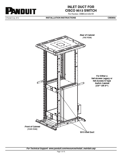
INSTALLATION INSTRUCTIONS ©Panduit Corp.2012CM589AFor Either aNet-Access Legacy or Net-Access N-Type Switch Cabinet (CN** OR N**)INLET DUCT FOR CISCO 9513SWITCHPart Number:DIBBC2314S21WCOMPONENT GUIDE(2) Upper Adjustable Brackets(2) Lower Adjustable BracketsLower InletBoxUpper InletBoxUpper Seal PlateLower Seal PlateSide DuctRear DuctNote: Upper RH Bracket Tools Needed:-Phillips Head Screwdriver -Socket Wrench-3/8” SocketHardware Supplied:INDEXRemoving Side Panel Bumpers...................................................................................................................................Determine Location of Duct..........................................................................................................................................Upper / Lower Left Hand Bracket Installation...............................................................................................................Upper / Lower Right Hand Bracket Installation.............................................................................................................Attaching Foam Seal to Side Duct (For Net-Access N-Type Cabinet)........................................................................Side Duct Installation - Day 1 (No Side Panel on Cabinet)...........................................................................................Side Duct Installation - Day 2 (With Side Panel on Cabinet)Separating Side Duct Sections................................................................................................................................. Side Duct Frame Installation.................................................................................................................................... Bump Out Installation...............................................................................................................................................Duct Seal Installation...................................................................................................................................................Upper / Lower Inlet Box Installation..............................................................................................................................Rear Duct Installation...................................................................................................................................................PAGE3456789101112131415Removing Side Panel Bumper•Unscrew and remove (4) #12-24 screws and (4) # 12 lock washers.•Remove Side Panel Bumper.Determine Location of Duct•Ducting requires (20) rack units for installation. Duct components can be installed before or after switch installation and are NOT designed to support the switch.•The front equipment rails need to be in the full forward position.•Rear equipment rails need to be located 24.25" to 26.0" from the front rails.•Due to physical constraints posed by the front-to-back frame beams on the legacy Net-Access Cabinet, the inlet duct can only be installed in one location.•For new Net-Access switch cabinets (N***), the only restriction is that 3 RU must be left open above and below the switch for inlet duct24.25"- 26.0" fromEquipment RailEquipment RailNutsNutsUpper Left Hand BracketHand BracketRear of Cabinet (Hot Aisle)•Attach upper adjustable bracket to upper left hand bracket with (2) #10-32 nuts. (Leave nuts loose.)•Attach lower adjustable bracket to lower left hand bracket with (2) #10-32 nuts. (Leave nuts loose.)•Measure distance between front and rear rails.•Adjust brackets to fit front and rear rail distance. (Tighten nuts on brackets that were left loose.)•Install (1) upper left hand bracket with (4) #12-24 screws and (4) #12 star washers. (Leave screws loose until Inlet Box is installed.)•Install (1) lower left hand bracket with (4) #12-24 screws and (4) #12 star washers. (Leave screws loose until Inlet Box is installed.)Upper Adjustable Upper Right •Attach upper adjustable bracket to upper right hand bracket with (2) #10-32 nuts. (Leave nuts loose.)•Attach lower adjustable bracket to lower right hand bracket with (2) #10-32 nuts. (Leave nuts loose.)•Measure distance between front and rear rails.•Adjust brackets to fit front and rear rail distance. (Tighten nuts on brackets that were left loose.)•Install (1) upper right hand bracket with (4) #12-24 screws and (4) #12 star washers. (Leave screws loose until Inlet Box is installed.)•Install (1) lower right hand bracket with (4) #12-24 screws and (4) #12 star washers. (Leave screws loose until Inlet Box is installed.)Attaching Foam Seal to Side Duct.(For Net-Access N-Type Only)• Attach one strip of foam seal to flange on front of side duct.Flange(No Side Panel on Cabinet) Side Duct Installation•Slide (4) studs on side duct into (4) slots on right hand side brackets.•Secure side duct to brackets with (4) #10-32 nuts.(With Side Panel on Cabinet) Separating Side Duct Sections•Remove (4) #10-32 nuts from side duct assembly.•Separate side duct frame from bump out.Side Duct Frame Installation•From the rear of the cabinet insert the side duct frame into the cabinet.•Slide (4) studs on the inside of the side duct frame into the slots on the right side brackets.•Secure side duct frame to right side brackets with (4) #10-32 nuts.Front of Cabinet(4) #10-32 Nuts(4) SlotsBump Out Installation•Insert the bump out from the rear of the cabinet.•Slide the notches on the bump out on to the studs on the top and bottom of the side duct frame.•Secure the bump out to the frame with (4) #10-32 nuts.Front of CabinetDuct Seal Plate Installation•Slide upper seal plate studs through the holes in the top of the side duct and bracket.•Secure seal plate to side duct with (2) #10-32 nuts.•Repeat process for lower seal plate.Upper SealPlate•Slide upper inlet box into rails on the upper brackets so that studs on the upper brackets pass through the holes on the inlet box flanges.•Slide lower inlet box into rails on the lower brackets so that studs on the lower brackets pass though the holes on the inlet box flanges.•Secure the inlet boxes to the brackets with (4) #10-32 nuts.Box(4) #10-32 NutsFlange.•Slide the studs on the side of the rear duct into the slots on the sides of the bottom inlet box. Make sure bottom of the rear inlet duct slides into folds on the bottom inlet duct.•Secure the rear duct in place with (2) #10-32 nuts.•Tighten all screws that were previously left loose.(Cold Aisle)Inlet Box。
DC10600M101_1111_4X(T C N)数据手册说明书

广州大彩光电科技有限公司版权所有版本记录销售与服务广州大彩光电科技有限公司电话:************-601传真:************Email:*************(咨询和支持服务)网站:地址:广州黄埔区(科学城)玉树华新园C栋3楼网络零售官方旗舰店:https://目录1.硬件介绍 (1)1.1产品外观 (1)1.2硬件配置 (2)1.3调试工具 (2)2.产品规格 (3)3.可靠性测试 (6)3.1ESD测试 (6)3.1.1执行标准 (6)3.1.2测试环境 (6)3.1.3测试数据 (6)3.2高低温老化测试 (7)3.2.1测试环境 (7)3.2.2测试数据 (7)3.3群脉冲测试 (8)3.3.1执行标准 (8)3.3.2测试环境 (8)3.3.3测试数据 (8)3.4辐射测试 (8)3.4.1执行标准 (8)3.4.2测试环境 (9)3.4.3测试数据 (9)4.产品尺寸 (11)5.型号定义 (12)6.协议配置 (13)7. LUA脚本配置 (14)8.包装与物理尺寸 (15)9.产品架构 (16)10.开发软件 (17)10.1什么是虚拟串口屏 (17)10.2Keil与虚拟串口屏绑定调试 (18)11.开发文档 (19)12.免责声明 (20)1. 硬件介绍本章节主要介绍产品的一些外观参考图、硬件配置图和调试所需工具。
1.1 产品外观以下为该尺寸不同型号的外观参考图,如图1-1、图1-2、图1-3所示。
注:未涉及关键结构工艺修改或布局大调整,仅产品工艺或可靠性方面的变更迭代,公司不予对外发起变更,具体以收到的实物为准。
图1-1 10.1寸电阻触摸参考图图1-2 10.1寸电容触摸参考图图1-3 10.1寸无触摸参考图1.2 硬件配置以下为该尺寸产品硬件配置参考图,以电容屏举例说明,如图1-4所示。
图1-4硬件配置图1.3 调试工具以下为该产品调试工具参考图,以电容屏举例说明,如图1-5所示。
DC电源系列商品说明书
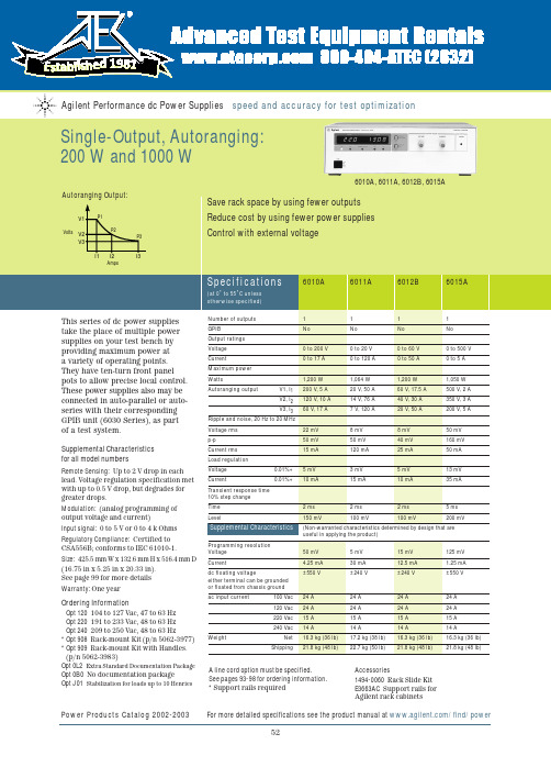
CSA556B; conforms to IEC 61010-1. Size:425.5 mm W x 132.6 mm H x 516.4 mm D (16.75 in x 5.25 in x 20.33 in). See page 99 for more details Warranty:One yearOrdering InformationOpt 120104 to 127 Vac, 47 to 63 Hz Opt 220191 to 233 Vac, 48 to 63 Hz Opt 240209 to 250 Vac, 48 to 63 Hz*Opt 908Rack-mount Kit (p/n 5062-3977)*Opt 909Rack-mount Kit with Handles.(p/n 5062-3983)Opt 0L2Extra Standard Documentation Package Opt 0B0No documentation packageOpt J01Stabilization for loads up to 10 HenriesPower Products Catalog 2002-2003 For more detailed specifications see the product manual at /find/power526010A, 6011A, 6012B, 6015AProgramming resolution Voltage 50 mV 5 mV 15 mV 125 mV Current4.25 mA 30 mA 12.5 mA 1.25 mA dc floating voltage±550 V±240 V±240 V±550 Veither terminal can be grounded or floated from chassis ground ac input current100 Vac 24 A 24 A 24 A 24 A 120 Vac 24 A 24 A 24 A 24 A 220 Vac 15 A 15 A 15 A 15 A 240 Vac14 A 14 A 14 A 14 A WeightNet 16.3 kg (36 lb) 17.2 kg (38 lb) 16.3 kg (36 lb) 16.3 kg (36 lb)Shipping21.8 kg (48 lb)22.7 kg (50 lb)21.8 kg (48 lb)21.8 kg (48 lb)A line cord option must be specified.See pages 93-98 for ordering information.*Support rails requiredAccessories1494-0060Rack Slide Kit E3663AC Support rails for Agilent rack cabinets6030A, 6031A,Power Products Catalog 2002-2003 For more detailed specifications see the product manual at /find/power5354for all model numbersRemote Sensing:Up to 2 V drop in each lead. Voltage regulation specification met with up to 0.5 V drop, but degrades for greater drops.Modulation: (analog programming of output voltage and current)Input signal:0 to 5 V or 0 to 4 k Ohms Size:6030A–32A, 6035A:425.5 mm W x 132.6 mm H x 503.7 mm D (16.75 in x 5.25 in x 19.83 in).6033A, 6038A:212.3 mm W x 177.0 mm H x 516.4 mm D (8.36 in x 6.97 in x 17.87 in).See page 99 for more details.Warranty: Three yearsOrdering InformationOpt 001 Front panel has only line switch, line indicator, and OVP adjust (6030A–33A and 6038A only)Opt 10087 to 106 Vac, 48 to 63 Hz(power supply output is derated to 75%)Opt 120 104 to 127 Vac, 47 to 63 Hz Opt 220191 to 233 Vac, 48 to 63 Hz Opt 240209 to 250 Vac, 48 to 63 Hz Opt 800Rack-mount Kit for Two Half-rack Units Side by Side. Lock link Kit p/n 5061-9694 and 7 in Rack adapter Kit 5063-9215*Opt 908Rack-mount Kit for a Single Half-rack Unit 6033A and 6038A(with blank filler panel); p/n 5062-3960, 6030A–32A and 6035A; p/n 5062-3977*Opt 909 Rack-mount Kit with Handles.For 6030A–32A, 6035A; p/n 5062-3983Power Products Catalog 2002-2003 For more detailed specifications see the product manual at /find/powerProgramming resolution Voltage50 mV 5 mV 15 mV 5 mV 125 mV 1 5 mV Current4.25 mA 30 mA 12.5 mA 7.5 mA 1.25 mA 2.5 mA dc floating voltage±550 V±240 V±240 V±240 V±550 V±240 Veither terminal can be grounded or floated from chassis ground ac input current100 Vac 24 A 24 A 24 A 6 A 24 A 6 A 120 Vac 24 A 24 A 24 A 6.5 A 24 A 6.5 A 220 Vac 15 A 15 A 15 A 3.8 A 15 A 3.8 A 240 Vac14 A 14 A 14 A 3.6 A 14 A 3.6 A WeightNet 16.3 kg 17.2 kg 16.3 kg 9.6 kg 16.3 kg 9.6 kg (36 lb) (38 lb) (36 lb) (21 lb) (36 lb) (21 lb)Shipping21.8 kg 22.7 kg 21.8 kg 11.4 kg 21.8 kg 11.4 kg (48 lb)(50 lb)(48 lb)(25 lb)(48 lb)(25 lb)Opt 0L2 Extra Standard Documentation Package Opt 0B3 Service ManualOpt 0B0 No documentation package Opt J01 Stabilization for loads up to 10 Henries (not available on 6033A)A line cord must be specified for 6030A-32A, 6035A. See pages 93-98 for ordering information.*Support rails required Accessories5080-2148Serial Link Cable, 2 m (6.6 ft)1494-0060Rack Slide KitE3663AC Support rails for Agilent rack cabinetsTo see a copy of the user’s guide, please visit our Web site at/find/manualsBy internet, phone, or fax, get assistance with all your test & measurement needs Online assistance:/find/assistPhone or FaxUnited States:(tel)180****4844Canada:(tel)187****4414(fax) (905) 282-6495China:(tel) 800-810-0189(fax) 1-0800-650-0121Europe:(tel) (31 20) 547 2323(fax) (31 20) 547 2390Japan:(tel) (81) 426 56 7832(fax) (81) 426 56 7840Korea:(tel) (82-2) 2004-5004 (fax) (82-2) 2004-5115Latin America:(tel) (305) 269 7500(fax) (305) 269 7599Taiwan:(tel) 080-004-7866 (fax) (886-2) 2545-6723Other Asia Pacific Countries:(tel) (65) 375-8100 (fax) (65) 836-0252Email:*******************Product specifications and descriptions in this document subject to change without notice.Your Requested Excerpt from the Agilent Power Products CatalogThe preceding page(s) are an excerpt from the 2002-2003 Power Products Catalog .We hope that these pages supply the information that you currently need. If you would like to have further information about the extensive selection of Agilent dc power supplies, ac sources, and dc electronic loads, please visit /find/power to print a copy of the complete Power Products catalog, or to request that a copy be sent to you. You will also find a lot of other useful information on this web site.In the full Power Products Catalog, you will find that Agilent offers much more than basic power generation. If you need basic, clean, power for your lab bench,it’s there. But in each product category, we’ve also integrated the capabilities that you need for a complete power solution, including extensive measurement and analysis capabilities.Please give us a call at your local Agilent Technologies sales office, or call a regional office listed below, for assistance in choosing or using Agilent power products.Keep up to date with Agilent’s Test and Measurement Email UpdatesAs an Email Update subscriber, you will receive periodic customized email updates that match the areas of interest that you have specified. Your update will include products and services, applications and support information, events,and promotions. Sign up today at /find/emailupdates . Check off dc power supplies, ac power sources or electronic loads on your registration form, and we will promptly let you know what’s new in power products! Our Privacy Statement at /go/privacy describes our commitment to you regarding your privacy.Agilent Technologies。
8740电子产品数据手册说明书
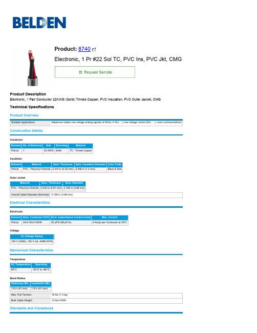
Pair(s) 20.6 Ohm/1000ft
30 pF/ft (98 pF/m)
6 Amps per Conductor at 30ºC
Voltage UL Voltage Rating
150 V (CMG), 150 V (UL AWM 2576)
Mechanical Characteristics
Indoor CA Prop 65 UL 1685 FT4 Loading, IEC 60332-1-2 CPR Euroclass: Eca Article 800, CMG AWM 2576 CMG EU CE Mark, EU Directive 2011/65/EU (RoHS 2), EU Directive 2012/19/EU (WEEE) UKCA Mark China RoHS II (GB/T 26572-2011)
16 lbs (7.3 kg) 12 lbs/1000ft
Standards and Compliance
Environmental Suitability: Sustainability: Flammability / Reaction to Fire: CPR Compliance: NEC / UL Compliance: AWM Compliance: CEC / C(UL) Compliance: European Directive Compliance: UK Regulation Compliance: APAC Compliance:
Pair(s) PVC - Polyvinyl Chloride 0.010 in (0.25 mm) 0.046 in (1.2 mm)
Black & Red
dc03材料

dc03材料DC03材料。
DC03材料是一种低碳冷轧板材,具有优良的成形性能和焊接性能,广泛应用于汽车制造、家电制造、建筑结构等领域。
本文将从材料特性、应用领域和加工工艺等方面对DC03材料进行详细介绍。
首先,DC03材料的主要特性包括低碳含量、良好的成形性能和焊接性能。
低碳含量使得该材料具有较好的冷成形性能,能够满足各种复杂零件的成形要求。
同时,DC03材料的焊接性能也非常优秀,能够满足各种焊接工艺的要求,保证焊接接头的牢固性和密封性。
因此,DC03材料在汽车制造、家电制造等领域有着广泛的应用。
其次,DC03材料在汽车制造领域的应用非常广泛。
汽车是对材料性能要求较高的行业,而DC03材料正是能够满足这一要求的理想材料。
它可以用于汽车车身、车门、车顶等部件的制造,不仅能够保证零部件的成形质量,还能够降低汽车的整体重量,提高汽车的燃油经济性。
此外,DC03材料还可以用于汽车底盘、悬挂系统等部件的制造,确保汽车在行驶过程中的稳定性和安全性。
另外,DC03材料在家电制造领域也有着重要的应用。
家电制造对材料的成形性能和表面质量要求较高,而DC03材料具有良好的成形性能和表面质量,能够满足家电制造的要求。
它可以用于制造冰箱、洗衣机、空调等家电产品的外壳和内部结构,确保产品的外观质量和使用性能。
最后,DC03材料在加工工艺方面也有其独特之处。
在冷成形加工过程中,DC03材料能够保持较好的成形性能,不易产生开裂和变形现象。
同时,它还能够通过多种焊接工艺进行连接,确保焊接接头的牢固性和密封性。
在涂装和表面处理方面,DC03材料也能够满足各种表面处理工艺的要求,保证产品的表面质量和耐腐蚀性能。
综上所述,DC03材料作为一种低碳冷轧板材,在汽车制造、家电制造等领域有着广泛的应用前景。
它的优良特性和良好加工工艺,使得它成为了许多制造行业的首选材料之一。
随着技术的不断进步和市场的不断需求,相信DC03材料将会有更广阔的发展空间,为各行业的发展贡献力量。
Recom RAC AC DC Converter 产品说明说明书

RAC AC/DC ConverterFeaturesRegulated Converter• Wide input range 85-305VAC• Standby mode optimized (eco design Lot 6)• High efficiency over the entire load range • Operating temperature range: -40°C to +90°C • Overvoltage and overcurrent protected• EMC compliant without external components • Encapsulated module with pins or wiredDescriptionThe RAC05-K/277 series are multipurpose 5 watt AC/DC power supplies for enhanced mains input conditions from 90VAC up to 305VAC with an extra wide operating temperature range from -40°C to +90°C. These modules are designed to supply worldwide applications in automation, Industry 4.0, IoT, household and smart buildings. For worldwide use they come with international safety certifications for industrial, domestic and ITE as well as household standards. With both PCB-mount and wired packages, fully protected outputs, and EMC class B emissions compliance without any external components, these are the easiest to use modular power solutions in the industry.E224736RAC05-__ SK/277/WModel NumberingOrdering Examples:RAC05-05SK/277 5 Watt 5Vout Single Output THT version RAC05-24SK/277 5 Watt 24Vout Single Output THT version RAC05-05SK/277/W 5 Watt 5Vout Single Output Wired version RAC05-12SK/277/W5 Watt 12Vout Single Output Wired versionS inglenom. Output PowerOutput Voltage5 Watt Single OutputRAC05-K/277Selection GuidePart Input Output Output Efficiency Max. CapacitiveNumber Voltage Range Voltage Current typ (1) Load (2)[VAC] [VDC] [mA] [%] [µF]RAC05-3.3SK/277 85-305 3.3 1510 77 10000RAC05-05SK/277 85-305 5 1000 80 8000RAC05-12SK/277 85-305 12 416 83 1500RAC05-15SK/277 85-305 15 330 83 1000RAC05-24SK/277 85-305 24 210 84 330Notes:Note1: Efficiency is tested at nominal input and full load at +25°C ambient Note2: Max Cap Load is tested at nominal input and full resistive loadW ired Notes:Note3: add suffix …W“ for wired versionwithout suffix, standard THT versionUL62368-1 certified EN62368-1 certified IEC/EN60335-1 certified EN62233 certifiedIEC/EN61558-1 certified IEC/EN61558-2-16 certified EN55032 compliantEN55014-1(-2) compliant CB ReportSpecifications(measured @ Ta= 25°C, nom. Vin, full load and after warm-up unless otherwise stated)Specifications (measured @ Ta= 25°C, nom. Vin, full load and after warm-up unless otherwise stated)REGULATIONSParameterConditionValueOutput Accuracy ±1.0% typ.Line Regulation low line to high line, full load±0.5% typ. Load Regulation (7)10% to 100% load 1.0% typ.Transient Response25% load step change4.0% max.recovery time500µs typ.PROTECTIONSParameterTypeValueInput Fuse (8)internal T1A, slow blowShort Circuit Protection (SCP)below 100m Whiccup, automatic restart Over Voltage Protection (OVP)125% - 195%, latch of modeOver Voltage Category OVC IIOver Current Protection (OCP)125% - 195%, hiccup modeClass of EquipmentClass IIIsolation Voltage (safety certified) (9)I/P to O/P1 minute4.2kVACIsolation Resistance Isolation Voltage 500VDC 1G W min.Isolation Capacitance 100pF max.Insulation Grade reinforced Leakage Current0.25mA max.continued on next pageDeviation vs. Load(at 115VAC, 230VAC, 277VAC)10.50-0.5-1D e v i a t i o n [%]102030405060708090100Output Load [%]10.5-0.5-1D e v i a t i o n [%]0102030405060708090100Output Load [%]RAC05-05SK/277RAC05-12SK/277Notes:Note8: Refer to local safety regulations if input over-current protection is also required Note9: For repeat Hi-Pot testing, reduce the time and/or the test voltageNotes:Note7: Operation below 10% load will not harm the converter, but specifications may not be metSpecifications(measured @ Ta= 25°C, nom. Vin, full load and after warm-up unless otherwise stated)Specifications(measured @ Ta= 25°C, nom. Vin, full load and after warm-up unless otherwise stated)SAFETY AND CERTIFICATIONSCertificate Type (Safety)Report / File Number StandardAudio/Video, information and communication technology equipment - Part 1: Safety requirements E491408-A6004-ULUL62368-1, 2nd Edition, 2014-12-01CAN/CSA-C22.2 No. 62368-1-14, 2nd Edt., 2014-12Audio/Video, information and communication technology equipment -Part 1: Safety requirements (CB Scheme)E491408-A6007-CB-1IEC62368-1:2014 2nd EditionAudio/Video, information and communication technology equipment -Part 1: Safety requirements (LVD)EN62368-1:2014 + A11:2017Household and similar electrical appliances - Safety -Part 1: General requirementsLCS190308001CS IEC60335-1:2010 + A2:2016 + C1:2016, 5th Edt.EN60335-1:2012 + A13:2017Measurement methods for electromagnetic fields of household appliances and similarapparatus with regard to human exposureEN62233:2008Safety of power transformers, power supplies, reactors and similar products for sup-ply voltages up to 1100 V (CB Scheme)50230493 001IEC61558-1:2005 2nd Edition + A1:2009Safety of power transformers, power supplies, reactors and similar products for sup-ply voltages up to 1100 V Part 2: Particular requirements (CB Scheme)IEC61558-2-16:2009 1st Edition + A1:2013 Safety of power transformers, power supplies, reactors and similar products for sup-ply voltages up to 1100 VEN61558-1:2005 + A1:2009 Safety of power transformers, power supplies, reactors and similar products for sup-ply voltages up to 1100 V Part 2: Particular requirementsEN61558-2-16:2009 + A1:2013 RoHS2RoHS-2011/65/EU + AM-2015/863 EMC Compliance Conditions Standard / Criterion Low-voltage power supplies DC output - Part 3: Electromagnetic compatibility EN61204-3: 2018, Class B Electromagnetic compatibility of multimedia equipment - Emission requirements (11)EN55032:2015, Class B Electromagnetic compatibility - Requirements for household appliances, electric toolsand similar apparatus - Part 1: EmissionEN55014-1:2006 + A2:2011 I nformation technology equipment - Immunity characteristics - Limits and methods of measurement EN55024:2010 + A1:2015 Electromagnetic compatibility - Requirements for household appliances, electric toolsand similar apparatus - Part 2: ImmunityEN55014-2:2015ESD Electrostatic discharge immunity testAir: ±2, 4, 8kVContact: ±2, 4kVEN61000-4-2: 2009, Criteria BRadiated, radio-frequency, electromagnetic field immunity test 10V/m, 80MHz-1GHz3V/m, 1.4GHz-2GHz1V/m, 2GHz-2.7GHzEN61000-4-3: 2006 + A1, 2009, Criteria AFast Transient and Burst Immunity AC and DC Port: ±2kV EN61000-4-4: 2012, Criteria BSurge Immunity AC In Port (L-N): ±1kVDC Output Port: ±0.5kVEN61000-4-5: 2014 +A1:2017, Criteria BImmunity to conducted disturbances, induced by radio-frequency fields AC and DC Port: 10V EN61000-4-6: 2014, Criteria A Power Magnetic Field Immunity50Hz, 30A/m EN61000-4-8: 2010, Criteria AVoltage Dips and InterruptionsVoltage Dips: 30%Voltage Dips: 60%Voltage Dips: 100%Interruptions: >95%EN61000-4-11:2004 + A1:2017, Criteria CEN61000-4-11:2004 + A1:2017, Criteria CEN61000-4-11:2014 + A1:2017, Criteria BEN61000-4-11: 2014 + A1:2017,Criteria CVoltage Fluctuations and Flicker in Public Low-Voltage Systems <=16A per phase EN61000-3-3: 2013 Limitations on the amount of electromagnetic interference allowed from digital and electronic devices FCC 47 CFR Part 15 Supbart B, Class B Methods of Measurement of Radio-Noise Emissions from Low-Voltage Electrical andElectronic Equipment in the Range of 9 kHz to 40 GHzANSI C63.4-2014, Class BNotes:Note11: If output is connected to GND, please contact RECOM tech support for adviceSpecifications(measured @ Ta= 25°C, nom. Vin, full load and after warm-up unless otherwise stated)Specifications (measured @ Ta= 25°C, nom. Vin, full load and after warm-up unless otherwise stated)The product information and specifications may be subject to changes even without prior written notice.The product has been designed for various applications; its suitability lies in the responsibility of each customer. The products are not authorized for use in safety-critical applications without RECOM’s explicit written consent. A safety-critical application is an application where a failure may reasonably be expected to endanger or cause loss of life, inflict bodily harm or damage property. The applicant shall indemnify and hold harmless RECOM, its affiliated companies and its representatives against any damage claims in connection with the unauthorizeduse of RECOM products in such safety-critical applications.PACKAGING INFORMATIONParameterTypeValuePackaging Dimension (LxWxH)THT wiredtube tray466.0 x 30.4 x 29.3mm 468.0 x 198.0 x 46.0mmPackaging Quantity THT wired12pcs 24pcsStorage Temperature Range -40°C to +85°C Storage Humiditynon-condensing 20% to 90% RH max.。
dc03的材料标准
dc03的材料标准DC03的材料标准。
DC03是一种冷轧低碳钢板材,具有良好的成型性能和焊接性能,广泛应用于汽车制造、家电制造、机械制造等领域。
DC03的材料标准对其化学成分、机械性能、表面质量等方面进行了详细规定,以确保产品质量和性能稳定。
下面将对DC03的材料标准进行详细介绍。
首先,DC03的化学成分主要包括碳含量、硅含量、锰含量、磷含量和硫含量。
其中,碳含量控制在0.10%以下,硅含量控制在0.03%以下,锰含量控制在0.45%以下,磷含量控制在0.035%以下,硫含量控制在0.035%以下。
这些化学成分的控制可以保证DC03钢板具有良好的成型性能和焊接性能。
其次,DC03的机械性能包括抗拉强度、屈服强度、延伸率等指标。
根据材料标准,DC03的抗拉强度范围为270-370MPa,屈服强度范围为140-270MPa,延伸率范围为38%以上。
这些机械性能指标的要求可以确保DC03钢板在加工过程中具有良好的强度和延展性,能够满足不同工艺要求的应用需求。
此外,DC03的材料标准还对其表面质量进行了严格规定。
表面质量主要包括表面处理、表面清洁度、表面平整度等方面。
根据标准规定,DC03钢板的表面应具有良好的清洁度,不得有明显的油污、锈斑和划痕;表面应平整,不得有凹凸不平和皱纹。
这些表面质量的要求可以确保DC03钢板在使用过程中具有良好的外观和加工性能。
总的来说,DC03的材料标准对其化学成分、机械性能、表面质量等方面进行了严格规定,以确保产品质量和性能稳定。
生产厂家在生产过程中应严格按照标准要求进行生产,确保产品符合标准要求。
同时,用户在选用DC03钢板时,应注意查看产品合格证书,确保产品质量可靠,符合要求。
通过对DC03的材料标准的详细介绍,相信大家对这一产品有了更深入的了解,同时也能更加准确地选择和应用这一产品,从而为相关行业的发展和应用提供更好的支持。
希望本文能对大家有所帮助,谢谢阅读。
DK106

功能描述DK106芯片是专用小功率开关电源控制芯片,广泛用于电源适配器、LED电源、电磁炉、空调、DVD等小家电产品。
一、产品特点•采用双芯片设计,高压开关管采用双极型晶体管设计,以降低产品成本;控制电路采用大规模MOS数字电路设计,并采用E极驱动方式驱动双极型晶体芯片,以提高高压开关管的安全耐压值。
内建自供电电路,不需要外部给芯片提供电源,有效的降低外部元件的数量及成本。
•芯片内集成了高压恒流启动电路,无需外部加启动电阻。
•内置过流保护电路,防过载保护电路,输出短路保护电路,温度保护电路及光藕失效保护电路。
•内置斜坡补偿电路,保证在低电压及大功率输出时的电路稳定。
•内置PWM振荡电路,并设有抖频功能,保证了良好的EMC特性。
•内置变频功能,待机时自动降低工作频率,在满足欧洲绿色能源标准(<0.3W)同时,降低了输出电压的纹波。
•内置高压保护,当输入母线电压高于保护电压时,芯片将自动关闭并进行延时重启。
•内建斜坡电流驱动电路,降低了芯片的功耗并提高了电路的效率。
•4KV防静电ESD测试。
二、功率范围输入电压(85∼264V ac)(85∼145V ac)(180∼264V ac)最大输出功率6W8W8W三、封装与引脚定义引脚符号功能描述1Gnd接地引脚。
2Gnd接地引脚。
3Fb反馈控制端。
4Vcc供电引脚。
5678Collector输出引脚,连接芯片内高压开关管Collector端,与开关变压器相连。
四、内部电路框图五、极限参数供电电压Vcc...........................................-0.3V--9V供电电流Vcc...........................................60mA引脚电压...........................................-0.3V--Vcc+0.3V 开关管耐压...........................................-0.3V--780V峰值电流...........................................400mA总耗散功率...........................................1000mW工作温度...........................................0℃--125℃储存温度...........................................-55℃--+150℃焊接温度...........................................+280℃/5S六、电气参数项目测试条件最小典型最大单位电源电压Vcc AC输入85V-----265V456V启动电压AC输入85V-----265V 4.85 5.2V关闭电压AC输入85V-----265V 3.64 4.2V电源电流Vcc=5V,Fb=2.2V102030mA 启动时间AC输入85V------500mS Collector保护电压L=2.4mH460480500V开关管耐压Ioc=1mA700------V开关管电流Vcc=5V,Fb=1.6V----3.6V320360400mA 峰值电流保护Vcc=5V,Fb=1.6V----3.6V380400420mA 振荡频率Vcc=5V,Fb=1.6V----2.8V606570KHz 变频频率Vcc=4.6V,Fb=2.8V----3.6V0.5--65KHz 抖频步进频率Vcc=4.6V,Fb=1.6V----2.8V0.81 1.2KHz 温度保护Vcc=4.6V,Fb=1.6V----3.6V120125130℃占空比Vcc=4.6V,Fb=1.6V----3.6V5---70%控制电压Fb AC输入85V-----265V 1.5--- 3.6V七、工作原理•上电启动:当外部电源上电时,直流高压经开关变压器传至芯片的COLLECTOR端(5678引脚),后经内建高压恒流启动电路将启动电流送至开关管Q1的B极,通过开关管Q1的电流放大(约为20倍放大)进入电源管理电路经D1为Vcc外部电容C1充电,同时为Fb预提供一个3.6V电压(Fb引脚对地应接入一只滤波电容),当Vcc的电压逐步上升至5V时,振荡器起振,电路开始工作,控制器为Fb开启一个约为25uA的对地电流源,电路进入正常工作。
欧诺克 直流伺服 驱动器 产品说明书

深圳市欧诺克科技有限公司Shenzhen ONKE Technology Co., Ltd.座机:*************27381841电话:邓先生135****7106陈先生139****0920邮箱:***************网 址 : 地址:广东省深圳市宝安区福海街道怀德翠湖工业园13栋稳定的质量是我们赖以生存的根本优质的服务是我们继续发展的前提客户的满意是我们唯一追求的目标产品画册Product gallery专业生产伺服驱动器、伺服电机及自动化控制系统深圳市欧诺克科技有限公司直流伺服驱动器目录匠心制造精益求精“一、公司介绍03二、直流伺服驱动器091.驱动器介绍与型号说明092.DC系列技术指标133.DE系列技术指标174.DE2系列技术指标215.BC系列技术指标256.驱动器应用领域297.驱动器外设配件31 0102C O M P A N Y PROFILE以精密制造引领未来Leading the future with precision manufacturing公司简介Company Profile深圳市欧诺克科技有限公司成立于2010年,是一家专业研发生产伺服电机和驱动器的高新技术企业,公司技术力量雄厚,检测手段先进,欧诺克人本着不求最全,只求最精的信念,为生产出各类伺服电机、各类驱动器而不懈奋斗。
欧诺克人以鹰的精神,挑战尖端,生产出性价比的各类伺服电机和驱动器,以鹰的敏锐洞察力洞察市场,随时改进、创新来满足市场的需求。
深圳市欧诺克科技有限公司产品主要有:伺服驱动器、伺服电机、直流伺服驱动器,直流伺服电机,交流伺服驱动器,交流伺服电机,低压伺服驱动器,低压伺服电机,直线电机驱动器,DDR马达驱动器,音圈电机驱动器,直流无刷驱动器,直流无刷电机,CANopen总线,EtherCAT总线,电子凸轮伺服系统,大功率伺服驱动器、大电流伺服驱动器,专用伺服驱动器和自动化控制系统,十年来凭借精湛的技术与国内国外众多知名企业公司建立了互利共赢的合作。
C106D1G中文资料
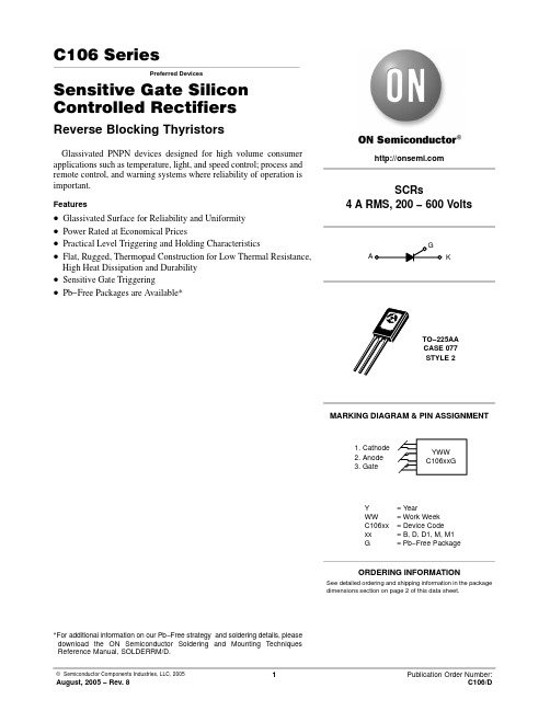
© Semiconductor Components Industries, LLC, 2005
1
August, 2005 − Rev. 8
Publication Order Number: C106/D
元器件交易网
C106 Series
MAXIMUM RATINGS (TJ = 25°C unless otherwise noted)
500 Units / Box
C106BG
TO−225AA (Pb−Free)
500 Units / Box
C106D
TO−225AA
500 Units / Box
C106DG
TO−225AA (Pb−Free)
500 Units / Box
C106D1*
TO−225AA
500 Units / Box
C106D1G*
TO−225AA (Pb−Free)
500 Units / Box
C106M
TO−225AA
500 Units / Box
C106MG
TO−225AA (Pb−Free)
500 Units / Box
C106M1*
TO−225AA
500 Units / Box
C106M1G*
TO−225AA (Pb−Free)
IGT
VGRM VGT
VGD
Latching Current (VAK = 12 V, IG = 20 mA)
Holding Current (VD = 12 Vdc) (Initiating Current = 20 mA, Gate Open)
DYNAMIC CHARACTERISTICS
Omega CDCN系列电导仪产品说明书
CDSA-1413
23
1413 µmho/cm conductivity solution, 946 mL (1 qt)
CDSA-1500
10
1500 µmho/cm conductivity solution, 946 mL (1 qt)
Comes complete with operator’s manual and 3V lithium battery. Probes sold separately.
RS232, RS485 RS232, RS485
RS232 RS232 RS232, RS485 RS232, RS485
Keypad/Display 5-button/one line 5-button/one line 5-button/one line 5-button/one line 16-button/four line 16-button/four line 16-button/four line 16-button/four line
PHA-7
5
7.00 pH buffer solution, 500 mL (1 pt) bottle
PHA-10
5
10.00 pH buffer solution, 500 mL (1 pt) bottle
CDSA-45
10
45 µmho/cm conductivity solution, 946 mL (1 qt)
ߜ Three Chemical Feed Programs (Conductivity, pH and Additive)
ߜ Langelier Saturation Index for Water Balance
DK106规格书
深圳东科半导体有限公司
离线式开关电源控制芯片
10uF/400V
C1
16电解电容Fra bibliotek22uF/10V
C4
1
470uF/25V
C5
1
2G103J
C2
1
8
瓷片电容
103瓷片
C3
1
Y电容102
C6
1
100K/0.5W
9
色环电阻
1K
R1
1
R2
1
10
IC
11
IC
12
变压器
DK106 EL817
EE13
IC1
1
IC2
工作温度 ………………………………………………………………… -25 ° C--+125 ° C
储存温度 ………………………………………………………………… -55 ° C--+150 ° C
焊接温度 ………………………………………………………………… +280 ° C/5S
DK106 Rev: V3
引脚电压 ……………………………………………………………… -0.3V--VDD+0.3V
功率管耐压 …………………………………………………………………… -0.3V--730V
峰值电流 ………………………………………………………………………… 400mA
总耗散功率 …………………………………………………………………… 1000mW
功能描述
1 HV 接外部启动电阻
2 GND 接地引脚
2
公 NC 空脚或接地
3
FB
反馈控制端引脚,接 1nF~10nF
dc03力学参数

dc03力学参数DC03是一种低碳钢,具有一些特殊的力学参数。
在本文中,我们将探讨DC03的力学参数及其在实际应用中的意义。
让我们来了解一下DC03的力学参数。
DC03的屈服强度为140-240MPa,抗拉强度为270-370MPa,延伸率为34-38%。
这些参数反映了材料在受力过程中的性能表现。
DC03的屈服强度是指在材料开始发生塑性变形之前所能承受的最大应力。
对于DC03来说,其屈服强度范围为140-240MPa,这意味着在未发生塑性变形之前,材料可以承受的最大应力在这个范围内变化。
屈服强度是衡量材料抗拉性能的重要指标之一,对于一些需要在受力情况下保持稳定形状的零件来说尤为重要。
抗拉强度是指材料在受拉破坏前所能承受的最大应力。
对于DC03来说,其抗拉强度范围为270-370MPa。
抗拉强度是衡量材料抗拉性能的重要指标,对于需要承受拉伸力的零件来说尤为重要。
抗拉强度越高,材料在受拉破坏前所能承受的应力越大,从而提高了零件的强度和可靠性。
延伸率是指材料在断裂前所能发生塑性变形的程度。
对于DC03来说,其延伸率范围为34-38%。
延伸率是衡量材料塑性变形能力的指标,对于需要承受冲击或振动载荷的零件来说尤为重要。
延伸率越高,材料在受力情况下发生塑性变形的能力越强,从而提高了零件的耐冲击性和耐振动性。
了解了DC03的力学参数,我们可以看到它具有一定的强度和塑性,适用于一些需要同时满足强度和可塑性要求的应用场景。
例如,DC03可以用于制造汽车车身零件,如车门、引擎盖等。
这些零件需要具有足够的强度以保护乘员和车辆安全,同时还需要具备一定的塑性以吸收碰撞能量。
DC03还可用于生产家电产品的外壳和结构零件。
家电产品通常需要具备一定的强度以承受正常使用过程中的载荷,同时还需要具备一定的塑性以应对异常情况下的冲击或挤压。
DC03作为一种低碳钢,具有较高的强度和塑性,非常适合用于这些应用。
DC03是一种具有特殊力学参数的低碳钢。
DC-3实样及说明书(压缩版)

DC-ⅢS型自动操舵仪使用说明书上海航海仪器责任公司2010年1月目 录1 概述------------------------------------------------------------------------------------------ 32 主要技术参数------------------------------------------------------------------------------ 33 系统组成------------------------------------------------------------------------------------ 3 3.1 配套------------------------------------------------------------------------------------------ 33.2 必需的配套仪器--------------------------------------------------------------------------- 44 仪器组成------------------------------------------------------------------------------------ 4 4.1 主操舵台------------------------------------------------------------------------------------ 4 4.1.1 泵启动和报警模块------------------------------------------------------------------------ 4 4.1.2 电源开关和电源组件--------------------------------------------------------------------- 4 4.1.3 系统选择开关------------------------------------------------------------------------------ 4 4.1.4 主/辅转换开关--------------------------------------------------------------------------- 4 4.1.5 动力定位模块------------------------------------------------------------------------------ 4 4.1.6 操舵模式选择开关------------------------------------------------------------------------ 4 4.1.7 主操舵台应急操舵开关------------------------------------------------------------------ 5 4.1.8 主操舵台随动手轮模块-------- --------------------------------------------------------- 5 4.1.9 控制器Ⅰ和控制器Ⅱ报警模块--------------------------------------------------------- 5 4.1.10 显示器模块--------------------------------------------------------------------------------- 5 4.2 辅操舵台------------------------------------------------------------------------------------ 6 4.2.1 舵角指示器--------------------------------------------------------------------------------- 6 4.2.2 辅操舵台模式选择开关------------------------------------------------------------------ 7 4.2.3 辅操随动信号发送模块------------------------------------------------------------------ 7 4.2.4 舵机应急操舵开关------------------------------------------------------------------------ 7 4.2.5 操舵地点指示灯和调光旋钮------------------------------------------------------------ 7 4.3 舵角反馈器--------------------------------------------------------------------------------- 7 4.4 操舵控制箱--------------------------------------------------------------------------------- 74.5 舵机启动箱--------------------------------------------------------------------------------- 75 操作说明------------------------------------------------------------------------------------ 7 5.1 启动与停止--------------------------------------------------------------------------------- 7 5.1.1 启动------------------------------------------------------------------------------------------ 7 5.1.2 停止------------------------------------------------------------------------------------------ 7 5.2 控制系统选择------------------------------------------------------------------------------ 8 5.3 操舵位置选择------------------------------------------------------------------------------ 8 5.4 动力定位操舵模式选择------------------------------------------------------------------ 8 5.5 主操舵台操舵------------------------------------------------------------------------------ 8 5.5.1 主操舵台自动操舵------------------------------------------------------------------------ 8 5.5.2 主操舵台随动操舵------------------------------------------------------------------------ 10 5.5.3 主操舵台应急操舵------------------------------------------------------------------------ 10 5.6 辅操舵台操舵------------------------------------------------------------------------------ 10 5.6.1 辅操舵台随动操舵------------------------------------------------------------------------ 10 5.6.2 辅操舵台应急操舵------------------------------------------------------------------------ 1015.7 舵机舱操舵--------------------------------------------------------------------------------- 10 5.8 综合状态显示------------------------------------------------------------------------------ 10 5.8.1 显示器调光--------------------------------------------------------------------------------- 10 5.8.2 语言选择------------------------------------------------------------------------------------ 11 5.9 操舵仪的报警系统------------------------------------------------------------------------ 11 5.9.1 操舵台报警--------------------------------------------------------------------------------- 11 5.9.2 舵机警报------------------------------------------------------------------------------------ 115.9.3 操舵仪控制系统失电--------------------------------------------------------------------- 116 安装------------------------------------------------------------------------------------------ 117 试验------------------------------------------------------------------------------------------ 12 7.1 系泊试验------------------------------------------------------------------------------------ 127.2 航行试验------------------------------------------------------------------------------------ 128 安全和维护保养--------------------------------------------------------------------------- 139 备品与备件--------------------------------------------------------------------------------- 1310 保证事项------------------------------------------------------------------------------------ 13 附图1-------------------------------------------------------------------------------------------------- 14 附图2-------------------------------------------------------------------------------------------------- 142DC-ⅢS型自动操舵仪使用说明书1 概述Ⅲ是一款具有高稳定性,全数字化,功能完备,可扩展性好等显著特点DC-S的新型自动操舵仪。
柯尼卡美能达bizhub C250_C252维修手册中文
柯尼卡美能达bizhub C250_C252维修手册中文2006.122006.12Ver. 3.0Ver. 3.02006.12 Ver. 3.02006.12 Ver. 3.0?? 2006 ?? 2006DD4038PC3-0800DD4038PC3-0800G4G4i现场维修总目录安全和重要警告事项 ..................................................................... ....................................S-1重要注意事项 ..................................................................... .........................................S-1危险事项、警告和注意的描述 ..................................................................... ................S-1安全警告 ..................................................................... ................................................S-2机器上的警告标识 ..................................................................... ................................S-18当发生意外时采取的措施 ..................................................................... ..........................S-20维修手册的构成 ..................................................................... ..........................................C-1维修手册的注释 ................................................................. ..............................................C-2bizhubC250/C252 主机概述.................................................................. ...............................................................1维修...................................................................... ...........................................................9调整/设置...................................................................... .............................................169故障排除...................................................................... ...............................................397附标准录...................................................................... .......................................................517控制器概述.................................................................. ...............................................................1维修...................................................................... ...........................................................3调整/设置...................................................................... ...............................................37故障排除...................................................................... .................................................39DF-601概述...................................................................... ...........................................................1维修...................................................................... ...........................................................5调整/设置.....................................................................................................................13故障排除...................................................................... .................................................29PC-103/PC-203概述.................................................................. ...............................................................1维修...................................................................... ...........................................................3调整/设置...................................................................... ...............................................13故障排除...................................................................... .................................................19PC-403概述...................................................................... ...........................................................1维修...................................................................... ...........................................................3调整/设置...................................................................... ...............................................17故障排除...................................................................... .................................................25bizhubC250_FS_Total_E TOC.fm Page i Friday January 5 2007 4:11 PMiiAD-503概述...................................................................... ..........................................................1维修...................................................................... ..........................................................3调整/设置...................................................................... ................................................7故障排除...................................................................... .................................................11FS-501概述...................................................................... ..........................................................1维修.................................................................. ..............................................................5调整/设置...................................................................... ................................................9故障排除...................................................................... .................................................19FS-514/PK-510/OT-601概述.................................................................. ..............................................................1维修...................................................................... ..........................................................7调整/设置...................................................................... ..............................................45故障排除...................................................................... .................................................59MT-501 概述...................................................................... ..........................................................1维修...................................................................... ..........................................................3调整/设置...................................................................... ................................................7故障排除...................................................................... .................................................13SD-503概述...................................................................... ..........................................................1维/修...................................................................... ..........................................................3调整设置...................................................................... ..............................................25故障排除...................................................................... .................................................37FS-603概述...................................................................... ..........................................................1维修...................................................................... ..........................................................5调整/设置...................................................................... ..............................................23故障排除...................................................................... .................................................51bizhubC250_FS_Total_E TOC.fm Page ii Friday January 5 2007 4:11 PM安全和重要警告事项S-1在进行维修工作前请仔细阅读如下所述的安全和重要警告事项并充分理解其含义。
民航百科航空器介绍 麦克唐纳.道格拉斯DC-10系列介绍

民航百科-航空器介绍麦克唐纳·道格拉斯DC-10系列介绍DC-10简介:麦克唐纳·道格拉斯公司DC-10DC-10是美国麦克唐纳·道格拉斯公司(简称麦道公司)研制的三发中远程宽机身客机。
1966年4月,美国几家主要航空公司提出70年代需要一种经济性好、航程在3000公里以上、载客量300人左右的大型客机。
麦道公司为了满足这一要求,开始DC-10方案的研究。
DC-10的最初设计方案为双发翼下吊舱、双层客舱布局,类似于今天的波音747。
后经过论证,改为三发单层客舱宽机身方案。
这种客机既可以经济地横跨美国本土,又可飞越大洋。
所以DC-10既可飞美国国内航线又可飞国际航线,载客量300~350人。
该机于1966年年中开始设计,1967年1月开始制造原型机,1970年7月第一架原型机出厂,1970年8月29日首次试飞,1971年7月29日获美国联邦航空局型号合格证,同一天交付美国航空公司,8月5日首航洛杉矶至芝加哥航线。
DC-10各型飞机,共获订货386架,最后1架已于1989年春交付完毕。
由DC-10飞机改装的空中加油机KC-10,共获美国空军订货60架,1990年4月4日交付完毕。
DC-10主要型号:DC-10-10:基本型。
最大起飞重量185970千克,装3台通用电气公司CF6-6D涡轮风扇发动机,单台推力182.4千牛(18597公斤)。
适用于中短程航线使用。
1970年8月29日首飞,1971年7月29日获美国联邦航空局型号合格证,1971年8月5日投入航线使用。
最大载客量345人。
截止1986年12月,该型共交付133架。
DC-10-15:与基本型基本相同,但换装3台通用电气公司的CF6-50C2F涡扇发动机,单台推力207千牛(21122公斤)。
该型最大起飞重量206385千克,于1981年1月8日首飞,1981年6月12日获得型号合格证。
共生产7架。
DC-10-30:远程型。
MORNSUN LS08-13BxxSS系列AC DC电源说明书
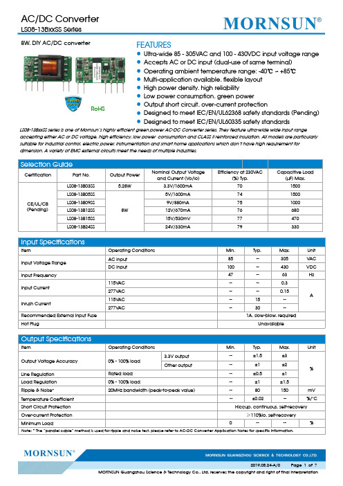
8W,DIY AC/DC converterRoHSFEATURES●Ultra-wide 85-305VAC and 100-430VDC input voltage range ●Accepts AC or DC input (dual-use of same terminal)●Operating ambient temperature range:-40℃~+85℃●Multi-application available,flexible layout ●High power density,high reliability●Low power consumption,green power●Output short circuit,over-current protection●Designed to meet IEC/EN/UL62368safety standards (Pending)●Designed to meet IEC/EN/UL60335safety standardsLS08-13BxxSS series is one of Mornsun’s highly efficient green power AC-DC Converter series.They feature ultra-wide wide input rangeaccepting either AC or DC voltage,high efficiency,low power consumption and CLASS II reinforced insulation.All models are particularly suitable for industrial control,electric power,instrumentation and smart home applications which don’t have high requirement for dimension.A variety of EMC external circuits meet the needs of multiple industries.Input SpecificationsItemOperating Conditions Min.Typ.Max.Unit Input Voltage Range AC input 85--305V AC DC input100--430VDC Input Frequency 47--63HzInput Current 115V AC ----0.3A 277V AC ----0.15Inrush Current115V AC --15--277V AC--30--Recommended External Input Fuse 1A,slow-blow,requiredHot PlugUnavailableOutput SpecificationsItemOperating Conditions Min.Typ.Max.UnitOutput Voltage Accuracy 0%-100%load 3.3V output --±1.5±3%Other output--±1±2Line Regulation Rated load --±0.5±1Load Regulation 0%-100%load--±1±1.5Ripple &Noise *20MHz bandwidth (peak-to-peak value)--80150mV Temperature Coefficient --±0.02--%/°C Short Circuit Protection Hiccup,continuous,self-recoveryOver-current Protection ≥110%Io,self-recoveryMinimum Load----%Note:*The “parallel cable”method is used for ripple and noise test,please refer to AC-DC Converter Application Notes for specific information.Selection GuideCertificationPart No.Output PowerNominal Output Voltage and Current (Vo/Io)Efficiency at 230V AC(%)Typ.Capacitive Load(µF)Max.CE/UL/CB (Pending)LS08-13B03SS 5.28W3.3V/1600mA 701500LS08-13B05SS8W 5V/1600mA 741500LS08-13B09SS 9V/880mA 751000LS08-13B12SS 12V/670mA 76680LS08-13B15SS 15V/530mV 77470LS08-13B24SS24V/330mA79330General SpecificationsItem Operating Conditions Min.Typ.Max.UnitIsolation Test Input-output Electric Strength Test for1min.,(leakage current<5mA)3000----VACOperating Temperature-40--+85℃Storage Temperature-40--+105Storage Humidity----95%RHPower Derating -40℃~-25℃ 2.67----%/℃+55℃~+85℃ 2.5----85V AC-100VAC1----277V AC-305V AC0.54----Safety Standard IEC/EN/UL62368,IEC/EN/UL60335 Safety Certification IEC/EN/UL62368(Pending) Safety CLASS CLASS IIMTBF MIL-HDBK-217F@25°C>300,000h Mechanical SpecificationsCase Material44.50x24.00x15.00mmWeight11g(Typ.)Cooling method Free air convectionElectromagnetic Compatibility(EMC)Emissions CECISPR32/EN55032CLASS A(Recommended circuit1,4)CISPR32/EN55032CLASS B(Recommended circuit2,3) RECISPR32/EN55032CLASS A(Recommended circuit1,4)CISPR32/EN55032CLASS B(Recommended circuit2,3)Immunity ESD IEC/EN61000-4-2Contact±6KV Perf.Criteria B RS IEC/EN61000-4-310V/m perf.Criteria AEFTIEC/EN61000-4-4±2KV(Recommended circuit1,2)perf.Criteria BIEC/EN61000-4-4±4KV(Recommended circuit3,4)perf.Criteria B SurgeIEC/EN61000-4-5line to line±1KV(Recommended circuit1,2)perf.Criteria BIEC/EN61000-4-5line to line±2KV(Recommended circuit3,4)IEC/EN61000-4-5line to line±4KV(Recommended circuit4)perf.Criteria B CS IEC/EN61000-4-610Vr.m.s perf.Criteria A Voltage dips,shortinterruptions and voltagevariations immunityIEC/EN61000-4-110%,70%perf.Criteria BProduct Characteristic CurveNote:①With an AC input between85-100VAC/277-305VAC and a DC input between100-120VDC/390-430VDC,the output power must be derated as per temperature derating curves;②This product is suitable for applications using natural air cooling;for applications in closed environment please consult factory or one of our FAE.Additional Circuits Design ReferenceLS series additional circuits design referenceLS08series additional components selection guidePart No.FUSE(required)C1required)C2(required)L1(required)C3(required )C4CY1(required )LS08-13B03SS 1A/300V22µF/450V470µF/16V(solid-state capacitor) 4.7µH 150µF/35V 0.1µF/50V1.0nF/400V ACLS08-13B05SS LS08-13B09SS 220µF/16V(solid-state capacitor)100µF/35V LS08-13B12SS LS08-13B15SS 470uF/35V 47µF/35VLS08-13B24SS220uF/35VNote:1.C1:input capacitors,C2:output storage capacitors,they must be connected externally.2.We recommend using an electrolytic capacitor with high frequency and low ESR rating for C3(refer to manufacture’s datasheet).Combined with C2,L1,they form a pi-type filter circuit.Choose a capacitor voltage rating with at least 20%margin,in other words not exceeding 80%.C4is a ceramic capacitor,used for filtering high frequency noise.A suppressor diode (TVS)is a recommended to protect the application in case of a converter failure and specification should be 1.2times of the output voltage.Immunity design circuits for referenceEmissions design circuits for referenceCLASS ⅢCLASS ⅣCLASS ACLASS BEnvironmental Application EMC SolutionLS series environmental application EMC solution selection tableRecommendedcircuit Application environmental Typical industryInput voltagerangeEnvironment temperature Emissions Immunity 1Basic applicationNone85~305V AC -40℃~+85℃CLASS A CLASS Ⅲ2Indoor civil environment Smart home/Home appliances(2Y)-25℃~+55℃CLASS BCLASS ⅢIndoor general environment Intelligent building/Intelligentagriculture 3Indoor industrial environment Manufacturing workshop -25℃~+55℃CLASS B CLASS Ⅳ4Outdoor general environmentITS/Video monitoring/Charging point/Communication/Securityand protection-40℃~+85℃CLASS ACLASS ⅣOutdoor harsh environmentOn-line power meter Communication base station-40℃~+85℃CLASS A>CLASS ⅣSurge:line to ground ±4KV EFT:CLASS ⅣElectromagnetic Compatibility Solution--Recommended Circuit1.Recommended circuit 1——Basic applicationrecommended circuit 1Application environmentalAmbient temperature rangeImmunity CLASSEmissions CLASSBasic application-40℃~+85℃CLASS ⅢCLASS AComponentRecommended valueR112Ω/3W LDM4.7mH2.Recommended circuit 2——Indoor civil /Universal system recommended circuits for general environmentRecommended circuit 2Application environmentalAmbient temperature rangeImmunity CLASSEmissions CLASS Indoor civil /general -25℃~+55℃CLASS ⅢCLASS BComponentRecommended valueR112Ω/3W CY1(CY2) 1.0nF/400V ACLCM 3.5mH LDM 0.33mH CX0.1µF/310VAC FUSE (required)1A/300V ,slow-blowNote:In the home appliance application environment,the two Y capacitors of the primary and secondary need to be externally connected (CY1/CY2,value at 2.2nF/400VAC),which can meet the EN60335certification.In other industries,only one Y capacitor is needed.3.Recommended circuit 3——Universal system recommended circuits for indoor industrial environmentRecommended circuit 3Application environmental Ambienttemperature rangeImmunity CLASSEmissions CLASSIndoor industrial-25℃~+55℃CLASS ⅣCLASS BComponentRecommended valueMOV S14K350C1450V/22uF CY1 2.2nF/400V AC CX 0.1µF/310V ACLCM 3.5mH LDM 0.33mH R112Ω/3WFUSE (required)2A/300V ,slow-blow4.Recommended circuit 4——Universal system recommended circuits for outdoor general/harsh environmentRecommended circuit 4Application environmental Ambienttemperature rangeImmunity CLASSEmissions CLASSOutdoor general environment-40℃~+85℃CLASS ⅣCLASS AComponentRecommended valueMOV S14K350C1450V/22uF LDM 4.7mH R112Ω/3WFUSE (required)2A/300V ,slow-blowApplication environmental Ambient temperaturerangeImmunity CLASS EmissionsCLASSOutdoor harsh environment -40℃~+85℃>CLASSⅣSurge:line to ground±4KVEFT:CLASSⅣCLASS AComponent Recommended valueMOV S20K350C1450V/33uF(Surge protection priority)LDM 4.7mHR133Ω/5WFUSE(required) 6.3A/300V,slow-blow5.For additional information please refer to application notes on . LS08-13BxxSS Dimensions and Recommended LayoutNote:1.For additional information on Product Packaging please refer to .Packaging bag number:58220032;2.External electrolytic capacitors are required to modules,more details refer to typical applications;3.This part is open frame,at least6.4mm safety distance between the primary and secondary external components of the module isneeded to meet the safety requirement;4.Unless otherwise specified,parameters in this datasheet were measured under the conditions of Ta=25℃,humidity<75%,nominal inputvoltage(115V and230V)and rated output load;5.In order to improve the efficiency at light load,there will be audible noise generated,but it does not affect product performance andreliability;6.Module required dispensing fixed after assembled;7.All index testing methods in this datasheet are based on our company corporate standards;8.We can provide product customization service,please contact our technicians directly for specific information;9.Products are related to laws and regulations:see"Features"and"EMC";10.Our products shall be classified according to ISO14001and related environmental laws and regulations,and shall be handled byqualified units.Mornsun Guangzhou Science&Technology Co.,Ltd.Address:No.5,Kehui St.1,Kehui Development Center,Science Ave.,Guangzhou Science City,Huangpu District,Guangzhou,P.R.China Tel:86-20-38601850Fax:86-20-38601272E-mail:***************。
DC03A资料
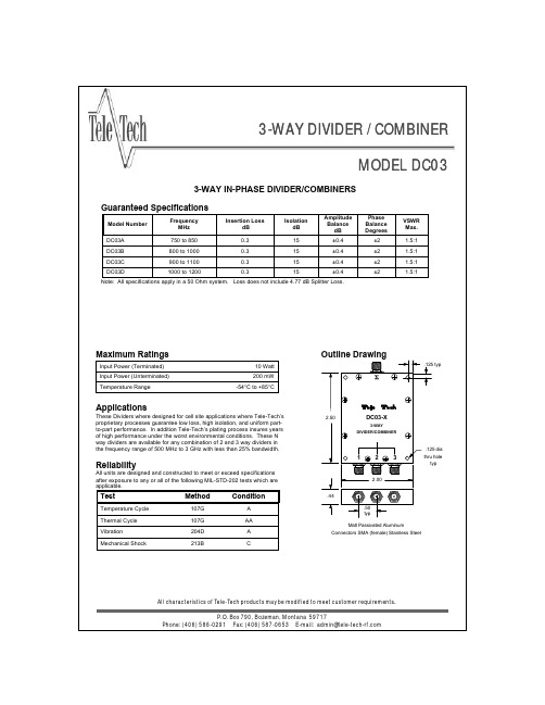
Method
107G 107G 204D 213B
Condition
A AA A C
All characteristics of Tele-Tech products may be modified to meet customer requirements. P.O. Box 790, Bozeman, Montana 59717 Phone: (406) 586-0291 Fax: (406) 587-0653 E-mail: admin@
Outline Drawing
.125 typ
Applications
These Dividers where designed for cell site applications where Tele-Tech’s proprietary processes guarantee low loss, high isolation, and uniform partto-part performance. In addition Tele-Tech’s plating process insures years of high performance under the worst environmental conditions. These N way dividers are available for any combination of 2 and 3 way dividers in the frequency range of 500 MHz to 3 GHz with less than 25% bandwidth.
Note: All specifications apply in a 50 Ohm system. Loss does not include 4.77 dB Splitter Loss.
SINOCERA称重传感器

SINOCERA称重传感器广州兰瑟电子科技有限公司
事业部内部使用资料
产品型号产品简介
CA-YD-103通用振动,冲击测量,压缩结构,~20PC/g
CA-YD-104通用,倒置压缩,~35PC/g,顶端L5 CA-YD-106通用压缩,低价,顶端L5,~25PC/g 产品型号产品简介
CL-YB-1(3-5T)用于动态轨迹衡、大吨位料斗秤等,量程3-5T,综合误差0.5% CL-YB-3(1.5-2T)用于料斗秤、吊钩秤等,量程1.5-2T,综合误差0.05%
CL-YB-3(5T)用于料斗秤、吊钩秤等,量程5T,综合误差0.05%
产品型号产品简介
CY-YB-1用于动静态气,液体的压力测量,量程0~5MPa,综合误差0.5%产品型号产品简介
CY-YD-200A发动机汽缸压力测量,水冷却管,~20PC/0.1MPa
CY-YD-201压电陶瓷敏感件,自由场冲击波测量>300PC/0.1MPa
CY-YD-202电气石敏感件,自由场冲击波测量,~30PC/0.1MPa
CY-YD-203小型石英压力传感器,F0>100KHz,~10PC/0.1MPa
CY-YD-205M10?安装螺纹,石英压力测量F0>100KHz,~10PC/0.1MPa
产品型号产品简介
CL-YD-301石英力传感器,5000N量程,~4PC/N
CL-YD-301A石英力传感器,高灵敏度,5000N量程,~8PC/N CL-YD-302拉压型,石英力传感器,~4PC/N。
- 1、下载文档前请自行甄别文档内容的完整性,平台不提供额外的编辑、内容补充、找答案等附加服务。
- 2、"仅部分预览"的文档,不可在线预览部分如存在完整性等问题,可反馈申请退款(可完整预览的文档不适用该条件!)。
- 3、如文档侵犯您的权益,请联系客服反馈,我们会尽快为您处理(人工客服工作时间:9:00-18:30)。
Notes: 1. All dimensions are in millimeters (inches), Tolerance is ±0.25(0.01")unless otherwise noted. 2. Specifications are subject to change without notice. 3.The gap between the reflector and PCB shall not exceed 0.25mm.
Typ. 610 601 29 15 2.1
Max.
Units nm nm nm pF
Test Conditions IF=20mA IF=20mA IF=20mA VF=0V;f=1MHz IFsolute Maximum Ratings at TA=25°C
Super Bright Orange 75 30 195 5 -40°C To +85°C
Units mW mA mA V
SPEC NO: DSAG1704 APPROVED: J. Lu
REV NO: V.3 CHECKED: Joe Lee
DATE: SEP/06/2006 DRAWN: Y.L.LI
元器件交易网
SURFACE MOUNT DISPLAY
Part Number: KCDC03-106 SUPER BRIGHT ORANGE
Features
0.3 INCH DIGIT HEIGHT. LOW CURRENT OPERATION. EXCELLENT CHARACTER APPEARANCE. I.C. COMPATIBLE. MECHANICALLY RUGGED. GRAY FACE,WHITE SEGMENT. PACKAGE :300PCS / REEL. MOISTURE SENSITIVITY LEVEL : LEVEL 4. RoHS COMPLIANT.
Note: 1.Luminous Intensity / Luminous Flux: +/-15%.
Electrical / Optical Characteristics at TA=25°C
Symbol λpeak λD ∆λ1/2 C VF IR
Notes: 1. Wavelength: +/-1nm. 2. Forward Voltage: +/-0.1V.
Parameter Power dissipation DC Forward Current Peak Forward Current [1] Reverse Voltage Operating/Storage Temperature
Note: 1. 1/10 Duty Cycle, 0.1ms Pulse Width.
SPEC NO: DSAG1704 APPROVED: J. Lu
REV NO: V.3 CHECKED: Joe Lee
DATE: SEP/06/2006 DRAWN: Y.L.LI
PAGE: 1 OF 4
元器件交易网
Selection Guide
Part No. Dice Lens Type Iv (ucd) [1] @ 10mA Min. KCDC03-106 SUPER BRIGHT ORANGE (InGaAlP) WHITE DIFFUSED 4700 Typ. 21371 Common Cathode, Rt. Hand Decimal. Description
REV NO: V.3 CHECKED: Joe Lee
DATE: SEP/06/2006 DRAWN: Y.L.LI
PAGE: 4 OF 4
Description
The Super Bright Orange source color devices are made with DH InGaAlP on GaAs substrate Light Emitting Diode.
Package Dimensions & Internal Circuit Diagram
PAGE: 2 OF 4
元器件交易网
Super Bright Orange
KCDC03-106
SPEC NO: DSAG1704 APPROVED: J. Lu
REV NO: V.3 CHECKED: Joe Lee
DATE: SEP/06/2006 DRAWN: Y.L.LI
PAGE: 3 OF 4
元器件交易网
KCDC03-106
Recommended Soldering Pattern (Units : mm;Tolerance:± 0.15)
Tape Specifications (Units : mm)
SPEC NO: DSAG1704 APPROVED: J. Lu
Parameter Peak Wavelength Dominant Wavelength Spectral Line Half-width Capacitance Forward Voltage Reverse Current
Device Super Bright Orange Super Bright Orange Super Bright Orange Super Bright Orange Super Bright Orange Super Bright Orange
