en61000-6-2&4 EMC%20TEST%20REPORT
(完整版)关于EMS测试项目最全的总结
EMC测试项目及仪器使用方法总结EMC包括EMI和EMS.●EMI (Electro-Magnetic Interference)电子电器产品工作时对周边外界环境的电磁干扰发放●EMS (Electro-Magnetic Susceptibility)电子电器产品在一定的电磁环境中工作时其本身对电磁干扰的敏感度●一般将环境分成两类:⏹A类(工业环境)。
例如,有工、科、医射频设备的环境;频繁切断大感性负载或大容性负载的环境;大电流并伴有强磁场环境等。
⏹B类(居民区、商业区及轻工业环境):例如:居民楼群、商业零售网点、商业大楼、公共娱乐场所、户外场所(如加油站、停车场、游乐场、公园、体育场)等EN61000-6-3 通用发射标准 B 类EN61000-6-4 通用发射标准 A 类EN61000-6-1 通用抗扰度标准 B 类EN61000-6-2 通用抗扰度标准 A 类●判断等级和试验结果的评估在EMS试验中,由于受试设备和系统的多样性和差异性,要对产品的不同测试项目评估判断等级.试验结果应该按受试设备的运行条件和功能规范进行如下分类。
a)在技术要求限值内性能正常;b)功能或性能暂时降低或丧失,但能自行恢复;C)功能或性能暂时降低或丧失,但需操作者干预或系统复位;d)因设备元件或软件损坏,或数据丢失而造成不能自行恢复至正常状态的功能降低或丧失。
EMS测试项目如下:(一)浪涌(冲击)抗扰度测试(Surge)Surge immunity test标准: GB/T17626.5IEC 61000-4-5(一)雷电产生浪涌电压的主要原理如下:A)直接雷击于外部电路,注入的大电流流过接地电阻或外部电路阻抗而产生电压B)在建筑物内,外导体上产生感应电压和电流的间接雷击C)附近直接对地放电的雷电入地电流耦合到设备组接地系统的公共接地路径(二)瞬态的模拟A)信号发生器的特性应尽可能地模拟上述现象B)如果干扰源与受试设备的端口在同一线路中,例如在电源网络中,那么信号发生器在受试设备的端口能够模拟一个低阻抗源C)如果干扰源与受试设备的端口不在同一线路中,那么信号发生器能够模拟一个高阻抗源(三)实验环境-环境温度:15℃~35℃-相对湿度:10%~75%-大气压力:86Kpa~106Kpa(四)试验等级等级开路试验电压(±10%)KV等级1 0.52 1.03 2.04 4.0(五)试验设备:组合波信号发生器●用于电源线实验的波形(1.2/50us和8/20us),开路电压波和短路电流波内阻:差模(线-线)2欧,共模(线-地)12欧输出极性:+/-试验次数:在选定点至少加五次正极性和五次负极性重复率:最快为每分钟一次当产品交流输入时:移相范围:0-270,一般为变化角度为90.直流输入时: 则不用设置相位,+/-各五次即可.●用于信号线实验的波形(10/700us)动态阻抗:40欧输出极性:+/-试验次数:在选定点至少加五次正极性和五次负极性重复率:最快为每分钟一次(二)静电放电抗扰度测试(ESD)Electrostatic discharge immunity test标准: GB/T17626.2IEC 61000-4-21.实验原理静电放电试验是模拟人体自身所带的静电在接触电子电气设备表面或周围金属物品时的放电。
半自动球泡组装机en标准

半自动球泡组装机en标准“EN标准”通常指的是欧洲标准(EuropeanNorm),是一系列由欧洲标准化委员会(CEN)和欧洲电气标准化委员会(CENELEC)制定的标准。
这些标准覆盖了各种产品、服务和流程,以确保它们的安全性、可靠性、互操作性和环境保护。
针对半自动球泡组装机,以下是适用的EN标准及其相关说明:一.设备安全标准:1.EN60204-1:这是有关机械和工业机器人的电气设备的标准。
它规定了电气设备的设计、安装和使用,以确保操作人员的安全。
2.ENISO12100:这是机械设备安全性的基本概念和一般原则的标准。
它提供了对半自动球泡组装机设计的风险评估和风险降低方法的指导。
二 .产品性能标准:1.EN12312-5:这是有关球泡机的标准,规定了球泡机的设计和性能要求,以确保其安全、可靠地运行。
2.EN13489:这是一般流体力学和流体控制装置的标准,可能适用于球泡机中的液压系统或气动系统。
三.机器操作标准:1.ENISO13857:这是机械设备上的安全距离的标准,指导设备设计者确保操作人员远离危险区域。
2.ENISO14121:这是有关机械安全风险评估的标准,对于半自动球泡组装机,它可以用来评估和减轻可能的安全风险。
四 .标识和说明标准:ENISO3864:这是安全标志和安全色彩的标准,它规定了在半自动球泡组装机上应该使用的标志和颜色,以提醒操作人员有关安全事项。
五 .环境标准:EN61000-6:这是电磁兼容性(EMC)的标准,它确保半自动球泡组装机在电磁环境中工作时不会产生干扰或受到干扰。
六 .健康和安全标准:ENISO12100-1:这是有关机械安全性的基本概念、设计原则和技术规范的标准。
它包括了半自动球泡组装机的设计和使用方面的健康和安全要求。
因此,在设计和使用半自动球泡组装机时,应该仔细研究并遵守适用的EN标准和其他相关法规。
工业环境电磁兼容性(EMC)指令:EN 61000-6-2:2005
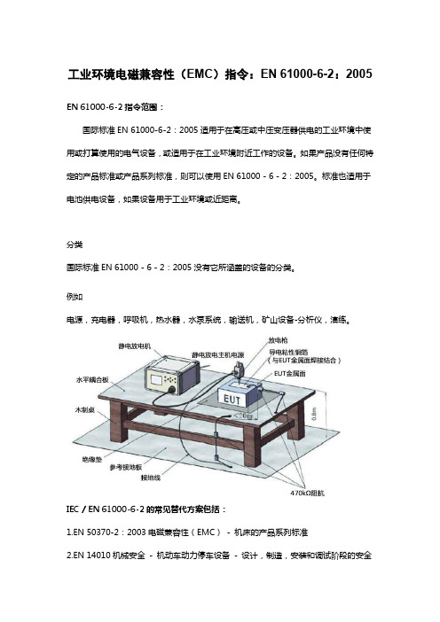
工业环境电磁兼容性(EMC)指令:EN 61000-6-2:2005 EN 61000-6-2指令范围:
国际标准EN 61000-6-2:2005适用于在高压或中压变压器供电的工业环境中使用或打算使用的电气设备,或适用于在工业环境附近工作的设备。
如果产品没有任何特定的产品标准或产品系列标准,则可以使用EN 61000 - 6 - 2:2005。
标准也适用于电池供电设备,如果设备用于工业环境或近距离。
分类
国际标准EN 61000 - 6 - 2:2005没有它所涵盖的设备的分类。
例如
电源,充电器,呼吸机,热水器,水泵系统,输送机,矿山设备-分析仪,演练。
IEC / EN 61000-6-2的常见替代方案包括:
1.EN 50370-2:2003电磁兼容性(EMC)- 机床的产品系列标准
2.EN 14010机械安全- 机动车动力停车设备- 设计,制造,安装和调试阶段的安全
和EMC要求
3.EN 61326-2-1:2013测量,控制和实验室用电气设备- EMC要求- 第2-1部分:特殊要求- EMC无保护应用的敏感测试和测量设备的测试配置,操作条件和性能标准。
常见产品EMC标准更新及到期日期一览表

EN 62233:2008 (IEC 62233:2005)
EN 60335-1:2012 (IEC 60335-1:2010, modified)
2012.12.1 2014-11-21
EN 50366:2003+ 2008.11.1 A1:2006
EN 50366:200 3
Clause 19.11.4 of EN 60335-1:2002+ A11: 2004+ A1: 2004+ A12: 2006+ A2: 2006+A13: 2008+A14:2010+ A15:2011
EN 55012:2007+A1:2009 (CISPR 12:2007+A1:2009)
2012.7.1
EN 55011: 2007+A2: 2007 (CISPR 11: 2003+A1: 2004+A2:2006)
2009.11.1
EN 55011: 1998+A1: 1999+A2: 2002
EN 55014-1:20 06 (CISPR 14-1:2005)
EN 55014-2: 1997
P 4 of 16
产品类别
标准名称
Product family standard
最新标准 =OJ 上已经列出来的标准
Dips 有60Hz需加做60Hz测试
“前一标准” 到期日期 OJ dow =最新标准必须
产品类别
标准名称
最新标准 =OJ 上已经列出来的标准
“前一标准” 到期日期 OJ dow =最新标准必须
执行的日期
“前一标准”
“旧标准” 到期日期 “旧标准” OJ dow
en55032和en61000标准线
en55032和en61000标准线
EN55032和EN61000-6-3都是电磁兼容性(EMC)标准,用于评估电子设备对电磁干扰的抗干扰能力。
以下是两者的主要区别:
1. 适用范围:
EN61000-6-3是一种通用标准,用于评估设备在现实环境中的电磁抗扰能力。
EN55032标准适用于广播通信设备和类似设备,如发射器、接收器、无线设备等。
2. 测试方法:
EN61000-6-3标准采用了多种测试方法,包括辐射和传导测试。
EN55032标准主要侧重于设备的辐射干扰测试,通过测量设备在其频率范围内的辐射电磁场来评估其抗扰能力。
3. 限值要求:
EN61000-6-3和EN55032标准都规定了设备在特定频率范围内的辐射和传导干扰限值要求。
然而,这些限值要求在两个标准中可能存在差异,因为它们适用于不同类型的设备和环境。
总的来说,EN55032和EN61000-6-3在适用范围、测试方法和限值要求等方面存在显著差异。
选择哪个标准取决于
具体的设备类型和应用场景。
en61000安规标准
en61000安规标准EN 61000安规标准是一套关于电磁兼容性的国际标准,由欧洲电工标准化委员会(CENELEC)制定并发布。
该标准旨在确保电气和电子设备在电磁环境中的正常工作,同时减少电磁干扰对其他设备的影响。
以下是对EN 61000安规标准的详细说明:一、概述EN 61000安规标准涵盖了电磁兼容性的多个方面,包括电磁干扰(EMI)和电磁抗扰度(EMS)。
这些标准适用于各种电气和电子设备,包括家用电器、工业设备、医疗设备、信息技术设备等。
通过遵循这些标准,制造商可以确保其产品在电磁环境中具有良好的性能,并满足国际市场和监管机构的要求。
二、标准分类1.EN 61000-1系列:基础标准和通用标准EN 61000-1-1和EN 61000-1-2是电磁兼容性的基础概念和定义的标准,提供了评估电气和电子设备电磁兼容性的基本方法和程序。
这些标准为后续的具体测试提供了指导和参考。
2.EN 61000-2系列:环境标准EN 61000-2系列标准主要关注电磁环境对设备的影响,包括电磁场的强度、频率等参数。
这些标准旨在确保设备在特定的电磁环境中能够正常工作,而不受干扰或损坏。
(注意:实际上,EN 61000-2系列并不存在。
可能是对标准编号的误解,通常我们讨论的是EN 61000的其他系列,如EN 61000-3、EN 61000-4等。
这里为了保持连贯性,我们假设存在一个虚拟的EN 61000-2系列,并将其解释为环境标准。
)3.EN 61000-3系列:限值标准EN 61000-3系列标准涉及到电源品质和稳定性的测量和控制。
这些标准规定了设备在电源输入端产生的电磁干扰的限值,以确保设备的正常工作不会对电网造成过大的干扰。
同时,这些标准还规定了设备对电源波动的抗扰度要求,以确保设备在电源质量较差的环境中也能正常工作。
4.EN 61000-4系列:测试方法和测量技术EN 61000-4系列标准涉及到各种类型的电磁干扰测试方法和测量技术。
欧盟的各类标准

欧美各国的安全标准和EMC标准2009-03-20 08:43欧美各国的安全标准和EMC标准一. 灯具类1. 固定在墙上或天花板上(壁灯/吊灯等)欧洲标准: EN60598-2—1美国标准: UL15982. 便携式灯具(台灯)欧洲标准: EN60598—2-4美国标准: UL1533. 灯串欧洲标准: EN60598-2—20美国标准: UL5884. 节能灯(带Ballast)欧洲标准: EN60968美国标准: UL935或UL19935. 小夜灯欧洲标准: EN60598美国标准: UL17866。
镇流器/电子变压器:欧洲标准: EN61347美国标准: UL935二. 电源产品1。
线性变压器A. 一般用途欧洲标准: EN61558美国标准: UL1310或UL1012B. 用于IT产品欧洲标准: EN60950美国标准: UL60950C. 用于AV产品欧洲标准: EN60065美国标准: UL6500 或 UL1411(电视机)2. 开关电源A. 一般用途,用于家电产品(如充电器) 欧洲标准: EN60335—2—29美国标准: UL1310或U1012B。
用于IT产品欧洲标准: EN60950美国标准: UL60950C. 用于AV产品欧洲标准: EN60065美国标准: UL6500 或UL1411(电视机)D。
用于医疗器械欧洲标准:美国标准: UL60601....三。
EMC电磁兼容检测项目:工业、医疗和科学产品电磁干扰检测 EN55011/ CISPR11音视频/广播类产品电磁干扰检测 EN55013/ CISPR13家电类产品电磁干扰检测 EN55014-1/ CISPR14家电类产品电磁抗干扰检测 EN55014—2灯具类产品电磁波干扰检测 EN55015/ CISPR15灯具类产品电磁波干扰检测 EN61547音视频/广播类产品电磁抗干扰检测 EN55020/CISPR20信息技术类产品电磁干扰检测 EN55022/ CISPR22信息技术类产品电磁抗干扰检测 EN55024/CISPR24居住、商业、轻工业环境下产品电磁抗干扰检测 EN61000-6—1 工业环境下产品电磁抗干扰检测 EN61000—6-2居住、商业、轻工业环境下产品电磁干扰检测 EN61000-6—3 工业环境下产品电磁干扰检测 EN61000-6—4电源谐波检测 EN60555-2/EN61000-3-2电压闪烁检测 EN60555-3/EN61000—3—3静电放电抗干扰检测 IEC/EN 61000-4—2射频电磁波抗干扰检测 IEC/EN 61000-4—3电性快速脉冲群抗干扰检测 IEC/EN 61000—4-4雷击抗干扰检测 IEC/EN 61000-4—5传导抗干扰检测 IEC/EN 61000—4-6电源频率磁场抗干扰检测 IEC/EN 61000—4-8电压瞬降抗干扰检测 IEC/EN 61000—4-11汽油车电磁干扰/抗干扰检测 EN55012交变湿热 Damp heat,cyclic IEC68—2—30恒定湿热Damp heat,steady state IEC68-2-67,IEC68—2—3 ◎电磁场评估(EMF): EN50366◎环境可靠性实验项目高温Dry heat IEC60068—2—2低温Cold IEC60068-2-1冲击Shock IEC68—2-27电子电气类一。
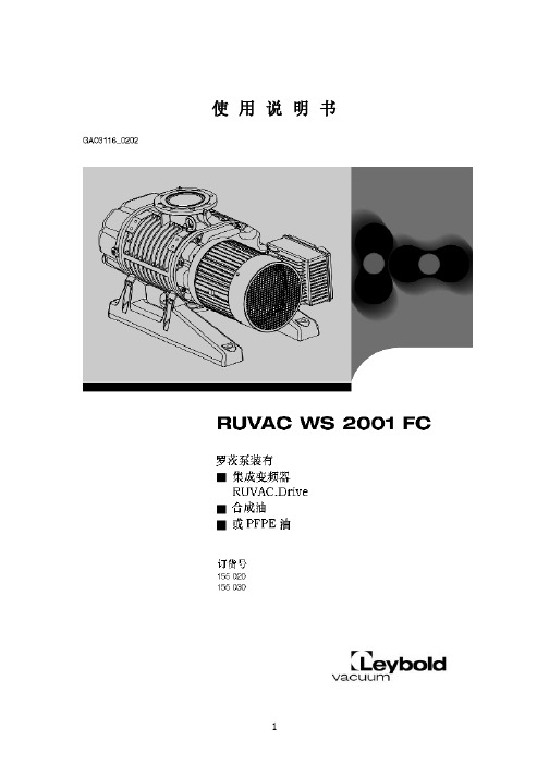
罗茨泵使用说明书
使用说明书目录章节页号重要安全考虑 (5)1. 简介 (9)1.1 设计和功能 (9)1.2 标准规格 (12)1.3 技术数据(SI单位) (13)1.4 附件 (17)2. 运输和贮存 (18)3. 安装与连接 (18)3.1 安装 (18)32 充入润滑油 (19)3.3 电气接线 (21)3.4 法兰连接 (24)4. 运行 (25)4.1 启动和用户指南(变频器) (25)4.2 启动 (33)4.3 运行 (33)4.4 停车和贮存 (34)4.5垂直抽气变为水平抽气 (34)5. 维护 (35)5.1 安全须知 (35)5.2 更换润滑油 (36)5.3 清理风扇罩和冷却翅片 (37)5.4 清洗入口保护网 (38)5.5 清洗泵腔 (38)5.6 常规维护 (39)5.7 莱宝维修 (40)6. 故障信息和故障排除 (40)6.1 变频器上的故障信息 (40)6.2 故障信息,注解 (42)6.3 泵故障排除 (44)符合EC声明 (47)图参考图-例如(1/2),依次表示图号和序号我们保留修改设计和给定数据的权利其中图例也不受限制莱宝维修如果将泵返回莱宝,必须说明泵中是否存在对人体健康有伤害的物质或是否已污染。
如果已污染还要说明危害性质。
如果没有污染声明,莱宝必然会将泵按地址返还给发货者。
废油处理在1986.11.1通过的废物处理修正法案(在德意志联系共和国内生效)中对使用过的油的处理有新条款。
按照废物处理法规,采取所谓因果律原则,因而,使用过的油的拥有者负有正确处理这些废物的责任。
来自真空泵的使用过的油不得与其它物质相混合。
来自真空泵使用过的油(莱宝矿物油),由于受到环境大气中氧气氧化、温度上升影响及机械磨损已受污染,所以必须按使用过油处理规程进行处理。
对受其它物质污染的真空泵使用过油必须做标识,按特殊废物依据污染分类贮存和处理。
如果将泵发往莱宝维修,必须注明在泵油内或在泵表面是否含有有害物质。
谈IEC 61000系列标准文件对电网谐波国标的指导作用

谈IEC 61000系列标准文件对电网谐波国标的指导作用作者:佚名文章来源:不详点击数:更新时间:2008-9-24 8:52:52摘要:国内正在采用IEC 61000系列标准文件,文中针对这套标准文件和电网谐波国标关系上的一些不同认识和理解,对照EIC 61000-3-6和《电能质量公用电网谐波》(GB/T 14549-1993)进行论述,以期达到提高认识,完善国家标准和正确执行标准的目的。
关键词:电磁兼容谐波国家标准0概述从1998年开始,我国发布的电磁兼容(EMC)标准中计有二三十项取自(等同或等效)国际电工委员会(IEC)近年来颁布的IEC 61000系列标准文件[1]。
众所周知,各种电气设备之间以电磁传导、感应和辐射3种方式彼此关联并相互影响,在一定的条件下会对设备的正常工作和人类造成干扰和危害。
20世纪80年代兴起的电磁兼容学科就是以研究和解决这方面问题为宗旨的。
该学科的着眼点是对干扰的产生、传播、接收、抑制机理以及相应的测量、计量技术进行深入的研究,在此基础上,根据经济、技术最合理的原则,对产生的干扰水平、抗干扰水平,以及抑制措施作出明确的规定,使处于同一电磁环境的设备都是"兼容"的。
也就是说,一个设备(或装置、系统)在其电磁环境中满意地执行其功能,而又不向该环境中的任何实体引入不能允许的电磁扰动。
EMC的基本任务是协调干扰发射者和承受者之间的关系,使其"兼容"。
协调的办法是制定合理且配套的规定值。
协调中所涉及的几个参数关系如图1所示。
图中横坐标为独立变量,如频率、电压偏差值、谐波含量、电压波动和闪变值、三相电压不平衡度等。
图1电磁兼容协调中的有关参数实际上EMC兼容水平是为了达到协调的目的而定出的一个参考值,有这一参考值便可以采用适当的方法和裕度,确定干扰源的发射限值以及电气设备抗干扰限值,从图1中可以一目了然。
IEC 61000系列标准包括6个部分:①总论,61000-1包括总的考虑(介绍、基本原则)、定义、术语;②环境,61000-2包括环境描述、环境的分类、兼容水平;③限值,61000-3包括发射限值、抗扰限值;④试验和测量技术,61000-4包括测量技术、试验技术;⑤安装和抑制导则,61000-5包括安装导则、抑制的方法和装置;⑥杂项,61000-6。
EN 61000-6-3_2007

EUROPEAN STANDARDEN 61000-6-3 NORME EUROPÉENNEEUROPÄISCHE NORM January 2007CENELECEuropean Committee for Electrotechnical StandardizationComité Européen de Normalisation ElectrotechniqueEuropäisches Komitee für Elektrotechnische NormungCentral Secretariat: rue de Stassart 35, B - 1050 Brussels© 2007 CENELEC -All rights of exploitation in any form and by any means reserved worldwide for CENELEC members.Ref. No. EN 61000-6-3:2007 EICS 33.100.10Supersedes EN 61000-6-3:2001 + A11:2004English versionElectromagnetic compatibility (EMC) -Part 6-3: Generic standards -Emission standard for residential, commercialand light-industrial environments(IEC 61000-6-3:2006)Compatibilité électromagnétique (CEM) - Partie 6-3: Normes génériques -Norme sur l'émissionpour les environnements résidentiels,commerciaux et de l'industrie légère(CEI 61000-6-3:2006)Elektromagnetische Verträglichkeit (EMV) - Teil 6-3: Fachgrundnormen - Störaussendung für Wohnbereich, Geschäfts- und Gewerbebereiche sowie Kleinbetriebe (IEC 61000-6-3:2006)This European Standard was approved by CENELEC on 2006-12-01. CENELEC members are bound to comply with the CEN/CENELEC Internal Regulations which stipulate the conditions for giving this European Standard the status of a national standard without any alteration.Up-to-date lists and bibliographical references concerning such national standards may be obtained on application to the Central Secretariat or to any CENELEC member.This European Standard exists in three official versions (English, French, German). A version in any other language made by translation under the responsibility of a CENELEC member into its own language and notified to the Central Secretariat has the same status as the official versions.CENELEC members are the national electrotechnical committees of Austria, Belgium, Bulgaria, Cyprus, the Czech Republic, Denmark, Estonia, Finland, France, Germany, Greece, Hungary, Iceland, Ireland, Italy, Latvia, Lithuania, Luxembourg, Malta, the Netherlands, Norway, Poland, Portugal, Romania, Slovakia, Slovenia, Spain, Sweden, Switzerland and the United Kingdom.EN 61000-6-3:2007 – 2 –ForewordThe text of document CISPR/H/121/FDIS, future edition 2 of IEC 61000-6-3, prepared by CISPR SC H, Limits for the protection of radio services, was submitted to the IEC-CENELEC parallel vote and was approved by CENELEC as EN 61000-6-3 on 2006-12-01.This European Standard supersedes EN 61000-6-3:2001 + A11:2004.The major changes in EN 61000-6-3:2007 are the inclusion of a clause on tests for equipment in series production, a new clause on measurement uncertainty and the inclusion of requirements on dc power ports and telecommunications ports. The informative annex has been deleted.The following dates were fixed:– latest date by which the EN has to be implementedat national level by publication of an identicalnational standard or by endorsement (dop) 2007-09-01– latest date by which the national standards conflictingwith the EN have to be withdrawn (dow) 2009-12-01This European Standard has been prepared under a mandate given to CENELEC by the European Commission and the European Free Trade Association and covers essential requirements of EC Directives EMC (89/336/EEC), EMC (2004/108/EC) and RTTED (1999/5/EC). See Annex ZZ.Annexes ZA and ZZ have been added by CENELEC.__________Endorsement noticeThe text of the International Standard IEC 61000-6-3:2006 was approved by CENELEC as a European Standard without any modification.__________EN 61000-6-3:20073– –CONTENTS INTRODUCTION (4)1Scope and object (5)2Normative references (6)3Terms and definitions (7)4Conditions during testing (8)5Product documentation (8)6Applicability (9)7Emission requirements (9)8Application of limits in tests for conformity of equipment in series production (9)9Measurement uncertainty (10)Annex ZA (normative) Normative references to international publications with their corresponding European publications (14)Annex ZZ (informative) Coverage of Essential Requirements of EC Directives (16)Bibliography (13)Figure 1 – Examples of ports (7)Table 1 − Emission (11)EN 61000-6-3:2007 – 4 –INTRODUCTIONIEC 61000 is published in separate parts according to the following structure:Part 1: GeneralGeneral considerations (introduction, fundamental principles)Definitions, terminologyPart 2: EnvironmentDescription of the environmentClassification of the environmentCompatibility levelsPart 3: LimitsEmission limitsImmunity limits (insofar as they do not fall under the responsibility of the product committees)Part 4: Testing and measurement techniquesMeasurement techniquesTesting techniquesPart 5: Installation and mitigation guidelinesInstallation guidelinesMitigation methods and devicesPart 6: Generic standardsPart 9: MiscellaneousEach part is further subdivided into several parts published either as International Standards or technical reports/specifications, some of which have already been published as sections. Others will be published with the part number followed by a dash and a second number identifying the subdivision (example: 61000-6-1).4EN 61000-6-3:20075– – ELECTROMAGNETIC COMPATIBILITY (EMC) –Part 6-3: Generic standards –Emission standard for residential,commercial and light-industrial environments1 Scope and objectThis part of IEC 61000 for EMC emission requirements applies to electrical and electronic apparatus intended for use in residential, commercial and light-industrial environments.Emission requirements in the frequency range 0 Hz to 400 GHz are covered. No measurement needs to be performed at frequencies where no requirement is specified.This generic EMC emission standard is applicable if no relevant dedicated product or product-family EMC emission standard exists.This standard applies to apparatus intended to be directly connected to a low-voltage public mains network or connected to a dedicated DC source, which is intended to interface between the apparatus and the low-voltage public mains network. This standard applies also to apparatus which is battery operated or is powered by a non-public, but non-industrial, low-voltage power distribution system if this apparatus is intended to be used in the locations described below.The environments encompassed by this standard are residential, commercial and light-industrial locations, both indoor and outdoor. The following list, although not comprehensive, gives an indication of locations that are included:– residential properties, for example houses, apartments;– retail outlets, for example shops, supermarkets;– business premises, for example offices, banks;– areas of public entertainment, for example cinemas, public bars, dance halls;– outdoor locations, for example petrol stations, car parks, amusement and sports centres;– light-industrial locations, for example workshops, laboratories, service centres.Locations that are characterised by being supplied directly at low voltage from the public mains network are considered to be residential, commercial or light-industrial.The object of this standard is to define the emission test requirements for apparatus defined in the scope in relation to continuous and transient, conducted and radiated disturbances.The emission requirements have been selected so as to ensure that disturbances generated by apparatus operating normally in residential, commercial and light-industrial locations do not exceed a level which could prevent other apparatus from operating as intended. Fault conditions of apparatus are not taken into account. Not all disturbance phenomena have been included for testing purposes in this standard but only those considered as relevant for the equipment covered by this standard. These requirements represent essential electromagnetic compatibility emission requirements.EN 61000-6-3:2007 – 6 –Requirements are specified for each port considered.NOTE 1 Safety considerations are not covered by this standard.NOTE 2 In special cases, situations will arise where the levels specified in this standard will not offer adequate protection; for example where a sensitive receiver is used in close proximity to an apparatus. In these instances, special mitigation measures may have to be employed.NOTE 3 As the requirements in this standard are more stringent than the requirements in IEC 61000-6-4, equipment fulfilling the requirements of this standard will also comply with the requirements of IEC 61000-6-4.2 Normative referencesThe following referenced documents are indispensable for the application of this document. For dated references, only the edition cited applies. For undated references, the latest edition of the referenced document (including any amendments) applies.IEC 61000-3-2, Electromagnetic compatibility (EMC) − Part 3-2: Limits − Limits for harmonic current emissions (equipment input current ≤16 A per phase)IEC 61000-3-3, Electromagnetic compatibility (EMC) − Part 3-3: Limits − Limitation of voltage fluctuations and flicker in low-voltage supply systems for equipment with rated current ≤16 AIEC 61000-3-11, Electromagnetic compatibility (EMC) – Part 3-11: Limits – Limitation of voltage changes, voltage fluctuations and flicker in public low-voltage supply systems – Equipment with rated current ≤75 A and subject to conditional connectionIEC 61000-3-12, Electromagnetic compatibility (EMC) – Part 3-12: Limits – Limits for harmonic currents produced by equipment connected to public low-voltage systems with input current >16 A and ≤75 A per phaseCISPR 14-1: Electromagnetic compatibility – Requirements for household appliances, electric tools and similar apparatus – Part 1: EmissionCISPR 16-1-2:2003, Specification for radio disturbance and immunity measuring apparatus and methods – Part 1-2: Radio disturbance and immunity measuring apparatus – Ancillary equipment – Conducted disturbancesCISPR 16-2-1:2003, Specification for radio disturbance and immunity measuring apparatus and methods – Part 2-1: Methods of measurement of disturbances and immunity – Conducted disturbance measurementsCISPR 16-2-3, Specification for radio disturbance and immunity measuring apparatus and methods – Part 2-3: Methods of measurement of disturbances and immunity – Radiated disturbance measurementsCISPR 16-4-2, Specification for radio disturbance and immunity measuring apparatus and methods – Part 4-2: Uncertainties, statistics and limit modelling – Uncertainty in EMC measurementsCISPR 22, Information technology equipment – Radio disturbance characteristics – Limits and methods of measurement6EN 61000-6-3:2007––73 Terms and definitionsFor the purposes of this document, the following terms and definitions apply.NOTE Definitions related to EMC and to relevant phenomena are given in IEC 60050-161 and in other IEC andCISPR publications.3.1portparticular interface of the specified apparatus with the external electromagnetic environment(see Figure 1)EnclosureportvoltageLowa.c. mains portApparatus Telecommunications/network port DC power portIEC 1091/06Figure 1 – Examples of ports3.2enclosure portphysical boundary of the apparatus which electromagnetic fields may radiate through orimpinge on3.3cable portport at which a conductor or a cable is connected to the apparatusNOTE Examples are signal, control and power ports.3.4telecommunications/network portpoint of connection for voice, data and signalling transfers intended to interconnect widelydispersed systems via such means as direct connection to multi-user telecommunicationsnetworks (e.g. public switched telecommunications networks (PSTN) integrated servicesdigital networks (ISDN), x-type digital subscriber lines (xDSL), etc.), local area networks (e.g.Ethernet, Token Ring, etc.) and similar networks)NOTE A port generally intended for interconnection of components of an ITE system under test (e.g. RS-232,RS-485, field buses in the scope of IEC 61158, IEEE Standard 1284 (parallel printer), Universal Serial Bus (USB),IEEE Standard 1394 (“Fire Wire”), etc.) and used in accordance with its functional specifications (e.g. for themaximum length of cable connected to it), is not considered to be a telecommunications port.3.5power portport at which a conductor or cable carrying the primary electrical power needed for theoperation (functioning) of an apparatus or associated apparatus is connected to the apparatusEN 61000-6-3:2007 – 8 –3.6public mains networkelectricity lines to which all categories of consumers have access and which are operated bya supply or distribution undertaking for the purpose of supplying electrical energy3.7low voltageLVlow tensionvoltage having a value below a conventionally adopted limit[IEV 601-01-26, modified]NOTE For the distribution of AC electric power, the upper limit is generally accepted to be 1 000 V.3.8d.c. power networklocal electricity supply network in the infrastructure of a certain site or building intended for flexible use by one ore more different types of equipment and guaranteeing continuous power supply independently from the conditions of the public mains networkNOTE Connection to a remote local battery is not regarded as a DC power network, if such a link comprises only power supply for a single piece of equipment.4 Conditions during testingThe equipment under test (EUT) shall be tested in the operating mode producing the largest emission in the frequency band being investigated, e.g. based on limited pre-tests and consistent with normal applications. The configuration of the test sample shall be varied to achieve maximum emission consistent with typical applications and installation practice.If the apparatus is part of a system, or can be connected to auxiliary apparatus, the apparatus shall be tested while connected to the minimum representative configuration of auxiliary apparatus necessary to exercise the ports in a similar manner to that described in CISPR 22.In cases where a manufacturer's specification requires external filtering and/or shielding devices or measures that are clearly specified in the user's manual, the measurement requirements of this standard shall be applied with the specified devices or measures in place.The configuration and mode of operation during the measurements shall be precisely noted in the test report. If the apparatus has a large number of similar ports or ports with many similar connections, a sufficient number shall be selected to simulate actual operating conditions and to ensure that all the different types of termination are covered.The measurements shall be carried out at one single set of parameters within the operating ranges of temperature, humidity and atmospheric pressure specified for the product and at the rated supply voltage, unless otherwise indicated in the basic standard.5 Product documentationThe purchaser/user shall be informed if special measures have to be taken to achieve compliance, e.g. the use of shielded or special cables.8– 9 – EN 61000-6-3:20076 ApplicabilityThe application of measurements for emission(s) depends on the particular apparatus, its configuration, its ports, its technology and its operating conditions.Measurements shall be applied to the relevant ports of the apparatus according to Table 1. Measurements shall only be carried out where the relevant ports exist.It may be determined from consideration of the electrical characteristics and usage of a particular apparatus that some of the measurements are inappropriate and therefore unnecessary. In such a case it is required that the decision and justification not to measure shall be recorded in the test report.7 Emission requirementsThe emission requirements for apparatus covered by this standard are given on a port by port basis.Measurements shall be conducted in a well-defined and reproducible manner.The measurements may be performed in any order.The description of the measurement, the measurement instrumentation, the measurement methods and the measurement set-up to be used are given in the standards, which are referred to in the Table 1.The contents of the standards referenced in the tables are not repeated here, however modifications or additional information needed for the practical application of the measurements are given in this standard.8 Application of limits in tests for conformity of equipment in series production8.1 Tests shall be made:– either on a sample of equipment of the type using the statistical method of evaluation setout in 8.2,– or, for simplicity’s sake, on one equipment only.8.2 Statistically assessed compliance with limits shall be made as follows.This test shall be performed on a sample of not less than five and not more than 12 items of the type. If, in exceptional circumstances, five items are not available, a sample of four or three shall be used. Compliance is judged from the following relationship:L kS x n ≤+ wherex is the arithmetic mean of the measured value of n items in the sample(∑=−−=ni i n n x x S 1112²x n is the value of the individual itemL is the appropriate limitEN 61000-6-3:2007 – 10 –k is the factor derived from tables of the non-central t-distribution which assures with 80 % confidence that 80 % of the type is below the limit; the value of k depends on the sample size n and is stated below.The quantities x n, x, S n and L are expressed logarithmically: dB(μV), dB(μV/m) or dB(pW).n 3 4 5 6 7 8 9 10 11 12 k 2,04 1,69 1,52 1,42 1,35 1,30 1,27 1,24 1,21 1,209 Measurement uncertaintyThe results of measurements of emissions from ITE shall reference the measurement instrumentation uncertainty considerations contained in CISPR 16-4-2.Determining compliance with the limits in this standard shall be based on the results of the compliance measurement, not taking into account measurement instrumentation uncertainty. However measurement uncertainty of the measurement instrumentation and its associated connections between the various instruments in the measurement chain shall be calculatedand both the measurement results and the calculated uncertainty shall appear in the test report.10T a b l e 1 − E m i s s i o nP o r t F r e q u e n c y r a n g eL i m i t s B a s i c s t a n d a r d A p p l i c a b i l i t y n o t e R e m a r k s1) E n c l o s u r e p o r t – O p e n a r e a t e s t s i t e o r s e m i -a n e c h o i c m e t h o d30 M H z – 230 M H z 230 M H z – 1 000 M H z30 d B (μV /m ) Q u a s i -p e a k a t 10 m 37 d B (μV /m ) Q u a s i -p e a k a t 10 mC I S P R 16-2-3 S e e N o t e s 1 a n d 4.M a y b e m e a s u r e d a t 3 m d i s t a n c e u s i n g t h e l i m i t s i n c r e a s e d b y 10 d B .2) L o w v o l t a g e A C m a i n s p o r t0 k H z – 2 k H zI E C 61000-3-2 I E C 61000-3-3I E C 61000-3-11 I E C 61000-3-12S e e N o t e s 2 a n d 3.0,15 M H z – 0,5 M H z66 d B (μV ) – 56 d B (μV ) q u a s i -p e a k 56 d B (μV ) – 46 d B (μV ) a v e r a g eC I S P R 16-2-1, 7.4.1C I S P R 16-1-2, 4.3S e e N o t e s 4 a n d 5.0,5 M H z – 5 M H z56 d B (μV ) q u a s i -p e a k 46 d B (μV ) a v e r a g e5 M H z – 30 M H z60 d B (μV ) q u a s i -p e a k 50 d B (μV ) a v e r a g e0,15 M H z – 30 M H zS e e b a s i c s t a n d a r d , c l a u s e : d i s c o n t i n u o u s d i s t u r b a n c e .C I S P R 14-1N O T E 1 I f t h e i n t e r n a l e m i s s i o n s o u r c e (s ) i s o p e r a t i n g a t a f r e q u e n c y b e l o w 9 k H z t h e n m e a s u r e m e n t s n e e d o n l y t o b e p e r f o r m e d u p t o 230 M H z .N O T E 2 A p p l i c a b l e t o a p p a r a t u s c o v e r e d w i t h i n t h e s c o p e o f I E C 61000-3-2, I E C 61000-3-3 o r I E C 61000-3-12.N O T E 3 I f t h e a p p a r a t u s i s c o v e r e d b y t h e s c o p e o f I E C 61000-3-11, t h i s m a y b e u s e d i n s t e a d o f I E C 61000-3-3.N O T E 4 A t t r a n s i t i o n a l f r e q u e n c i e s t h e l o w e r l i m i t a p p l i e s .N O T E 5 T h e l i m i t s d e c r e a s e l i n e a r l y w i t h t h e l o g a r i t h m o f t h e f r e q u e n c y i n t h e r a n g e 0,15 M H z t o 0,5 M H z .N O T E 6 T h e c u r r e n t a n d v o l t a g e d i s t u r b a n c e l i m i t s a r e d e r i v e d f o r u s e w i t h a n i m p e d a n c e s t a b i l i z a t i o n n e t w o r k (I S N ) w h i c h p r e s e n t s a c o m m o n m o d e (a s y m m e t r i c m o d e ) i m p e d a n c e o f150 Ω t o t h e t e l e c o m m u n i c a t i o n p o r t u n d e r t e s t (c o n v e r s i o n f a c t o r i s 20 l o g 10 150 / l = 44 d B ).– 11 – EN 61000-6-3:2007T a b l e 1 (c o n t i n u e d )P o r t F r e q u e n c y r a n g eL i m i t s B a s i c s t a n d a r d A p p l i c a b i l i t y n o t e R e m a r k s3) D C p o w e r p o r t0,15 M H z − 0,50 M H z 79 d B (μV ) q u a s i -p e a k 66 d B (μV ) a v e r a g eC I S P R 16-2-1, 7.4.1C I S P R 16-1-2, 4.3A p p l i c a b l e o n l y t o p o r t s i n t e n d e d f o r c o n n e c t i o n t o : - a l o c a l D C p o w e r n e t w o r k , o r- a r e m o t e l o c a l b a t t e r y b y a c o n n e c t i n g c a b l e e x c e e d i n g a l e n g t h o f 30 m .S e e n o t e 40,50 M H z − 30 M H z73 d B (μV ) q u a s i -p e a k 60 d B (μV ) a v e r a g e4) T e l e c o m m u n i c a t i o n s / n e t w o r k p o r t0,15 M H z – 0,5 M H z84 d B (μV ) – 74 d B (μV ) q u a s i -p e a k 74 d B (μV ) – 64 d B (μV ) a v e r a g e40 d B (μA ) – 30 d B (μA ) q u a s i -p e a k 30 d B (μA ) – 20 d B (μA ) a v e r a g eS e e n o t e s 4, 5 a n d 6.0,5 M H z – 30 M H z74 d B (μV ) q u a s i -p e a k 64 d B (μV ) a v e r a g e30 d B (μA ) q u a s i -p e a k 20 d B (μA ) a v e r a g eC I S P R 22 S e e n o t e s 4 a n d 6.N O T E 1 I f t h e i n t e r n a l e m i s s i o n s o u r c e (s ) i s o p e r a t i n g a t a f r e q u e n c y b e l o w 9 k H z t h e n m e a s u r e m e n t s n e e d o n l y t o b e p e r f o r m e d u p t o 230 M H z .N O T E 2 A p p l i c a b l e t o a p p a r a t u s c o v e r e d w i t h i n t h e s c o p e o f I E C 61000-3-2, I E C 61000-3-3 o r I E C 61000-3-12.N O T E 3 I f t h e a p p a r a t u s i s c o v e r e d b y t h e s c o p e o f I E C 61000-3-11 t h i s m a y b e u s e d i n s t e a d o f I E C 61000-3-3.N O T E 4 A t t r a n s i t i o n a l f r e q u e n c i e s t h e l o w e r l i m i t a p p l i e s .N O T E 5 T h e l i m i t s d e c r e a s e l i n e a r l y w i t h t h e l o g a r i t h m o f t h e f r e q u e n c y i n t h e r a n g e 0,15 M H z t o 0,5 M H z .N O T E 6 T h e c u r r e n t a n d v o l t a g e d i s t u r b a n c e l i m i t s a r e d e r i v e d f o r u s e w i t h a n i m p e d a n c e s t a b i l i z a t i o n n e t w o r k (I S N ) w h i c h p r e s e n t s a c o m m o n m o d e (a s y m m e t r i c m o d e ) i m p e d a n c e o f 150 Ω t o t h e t e l e c o m m u n i c a t i o n p o r t u n d e r t e s t (c o n v e r s i o n f a c t o r i s 20 l o g 10 150 / l = 44 d B ).EN 61000-6-3:2007– 12 –– 13 – EN 61000-6-3:2007BibliographyIEC 60050-161:1990, International Electrotechnical Vocabulary (IEV) − Chapter 161: Electro-magnetic compatibilityIEC 60050-601:1985, International Electrotechnical Vocabulary (IEV) – Chapter 601: Generation, transmission and distribution of electricity – GeneralIEC 61000-6-1, Electromagnetic compatibility (EMC) – Part 6-1: Generic standards – Immunity for residential, commercial and light-industrial environments IEC 61000-6-4, Electromagnetic compatibility (EMC) – Part 6-4: Generic standards – Emission standard for industrial environments___________NOTE Harmonized as EN 61000-6-1:2007 (not modified).NOTE Harmonized as EN 61000-6-4:2007 (not modified).Annex ZA(normative)Normative references to international publicationswith their corresponding European publicationsThe following referenced documents are indispensable for the application of this document. For dated references, only the edition cited applies. For undated references, the latest edition of the referenced document (including any amendments) applies.NOTE When an international publication has been modified by common modifications, indicated by (mod), the relevant EN/HD applies.Publication Year Title EN/HD Year IEC 61000-3-2 -1)Electromagnetic compatibility (EMC) -Part 3-2: Limits - Limits for harmonic currentemissions (equipment input current ≤16 A perphase)EN 61000-3-2 20062)IEC 61000-3-3 -1)Electromagnetic compatibility (EMC) -Part 3-3: Limits - Limitation of voltagechanges, voltage fluctuations and flicker inpublic low-voltage supply systems, forequipment with rated current ≤ 16 A perphase and not subject to conditionalconnection EN 61000-3-3+ corr. July19952)1997IEC 61000-3-11 -1)Electromagnetic compatibility (EMC) -Part 3-11: Limits - Limitation of voltagechanges, voltage fluctuations and flicker inpublic low-voltage supply systems -Equipment with rated current ≤ 75 A andsubject to conditional connectionEN 61000-3-11 20002)IEC 61000-3-12 -1)Electromagnetic compatibility (EMC) -Part 3-12: Limits -Limits for harmonic currentsproduced by equipment connected to publiclow-voltage systems with input current > 16 Aand ≤ 75 A per phaseEN 61000-3-12 20052)CISPR 14-1 -1)Electromagnetic compatibility - Requirementsfor household appliances, electric tools andsimilar apparatus -Part 1: EmissionEN 55014-1 20062)CISPR 16-1-2 2003 Specification for radio disturbance andimmunity measuring apparatus and methods -Part 1-2: Radio disturbance and immunitymeasuring apparatus - Ancillary equipment -Conducted disturbancesEN 55016-1-2 2004CISPR 16-2-1 2003 Specification for radio disturbance andimmunity measuring apparatus and methods -Part 2-1: Methods of measurement ofdisturbances and immunity - Conducteddisturbance measurementsEN 55016-2-1 20041)Undated reference.2)Valid edition at date of issue.EN 61000-6-3:2007 – 14 –1415 – EN 61000-6-3:2007 –Publication Year Title EN/HD YearEN 55016-2-3 20062) CISPR 16-2-3 -1)Specification for radio disturbance andimmunity measuring apparatus and methods -Part 2-3: Methods of measurement ofdisturbances and immunity - Radiateddisturbance measurementsEN 55016-4-2 20042) CISPR 16-4-2 -1)Specification for radio disturbance andimmunity measuring apparatus and methods -Part 4-2: Uncertainties, statistics and limitmodelling - Uncertainty in EMCmeasurementsEN 55022 20062) CISPR 22 -1)Information technology equipment - Radiodisturbance characteristics - Limits andmethods of measurementEN 61000-6-3:2007 – 16 –Annex ZZ(informative)Coverage of Essential Requirements of EC DirectivesThis European Standard has been prepared under a mandate given to CENELEC by the European Commission and the European Free Trade Association and within its scope the standard covers the essential requirements as given in Article 4(a) of the EC Directive 89/336/EEC and Annex I Article 1(a) of the EC Directive 2004/108/EC, and the essential requirements of Article 3.1(b) (emission only) of the EC Directive 1999/5/EC.Compliance with this standard provides one means of conformity with the specified essential requirements of the Directives concerned.WARNING: Other requirements and other EC Directives may be applicable to the products falling within the scope of this standard.__________。
倍福PLC卡件介绍
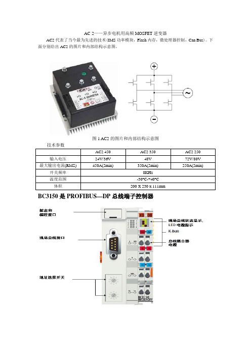
AC-2——异步电机用高频MOSFET逆变器AC2代表了当今最为先进的技术(IMS功率模块,Flash内存,微处理器控制,Can Bus)。
下面分别给出AC2的图片和内部结构示意图。
图1 AC2的图片和内部结构示意图BC3150是PROFIBUS—DP总线端子控制器总线端子控制器是带 PLC 控制功能的总线耦合器。
控制器有一个 PROFIBUS-DP 现场总线接口,可在 PROFIBUS-DP 系统中作为智能从站使用。
“紧凑型”总线端子控制器 BC3150 比较小巧而且经济。
BC3150 通过 K-BUS 总线扩展技术,可连接多达 255 个总线端子。
PROFIBUS 控制器自动检测波特率,最大可至 12 M波特率,使用两个地址选择开关分配地址。
总线端子控制器使用符合 IEC 61131-3 标准的 TwinCAT 进行编程。
组态和编程接口用于装载 PLC 程序,如果使用软件 PLC TwinCAT,则其 PLC 程序也可通过现场总线装载。
所连接的总线端子的输入/输出在 PLC 的缺省设置中被赋值。
可对每个总线端子进行配置,使其直接通过现场总线实现与上层控制单元的数据交换。
同样,预处理的数据也可通过现场总线实现总线端子控制器和上层控制器之间的数据交换。
BK3150是PRORIBUS—DP总线端子耦合器PROFIBUS-DP “紧凑型”总线耦合器 BK3150 扩展了 Beckhoff 总线端子系统,比较小巧而经济。
可以连接多达 64 个总线端子;若采用端子总线扩展技术,则可连接多达 255 个总线端子。
PROFIBUS 总线耦合器具有自动波特率检测功能,速率最大可以达到 12 Mbaud ,2 个地址选择开关用作地址分配。
对于现场总线连接,有提供 1 个 D-sub9 针接口,用于订货号为 ZS1031-3000 或 ZB3100 的 PROFIBUS 接头。
CX1020-0xxx 基本 CPU 模块CX1020 基本 CPU 模块通过一个功能更为强大的 1GHz Intel® M CPU 对现有CX1000 系列产品进行了扩展。
欧洲标准及其与IEC/CISPR标准对照一览表

1992
IEC 60601-1-2
医疗设备的EMC要求
EMC requirementsfor medical devices
[77A(See)134]
EN 60684,1991
IEC 60684,1992
有功交流静电电度表的EMC要求
EMC requirements 10r alternating current
EN 55011,1989
CISPR11,1990
工、科、医设备的发射要求
Emission requirements of ISM equipment [Withdrawn]
EN 55013,1993
CISPR13,1990
广播设备发射要求
Emission requirements for broadcast
欧洲标准及其与IEC/CISPR标准对照一览表
CENELEC编号
EC编号
CISPR编号
简略名称(Description)
EN 50065-l,1992
低压网络信号传输的发射要求(3kHz~148.5kHz)
EN 50081-l,1991
IEC 61000-6-3,1996
居民区、商业区和轻工业区发射,通用标准
EN 61000-2—9
IEC 61000-2-9,1996
HEMP的辐射骚扰
HEMP,radiated disturbance[77B(See)187]
EN 61000-3一2, 1995
IEC 61000-3一2,1995
谐波电流发射的限值
Limits for harmonic current emission
EMC测试项目详述

产品---系列标准概述Harmonic Flicker Radiated Emission (RE) Conducted Emission (CE) Electrostatic Discharge (ESD) RF electromagnetic field (RS) Fast transients (Burst/EFT) Surge Injected currents (CS) Power frequency magnetic field Voltage Dip and Interruptions EN 61000-3-2 (≤16A) EN 61000-3-3 (≤16A) EN 61000-6-4 EN 61000-6-4 IEC 61000-4-2 IEC 61000-4-3 IEC 61000-4-4 IEC 61000-4-5 IEC 61000-4-6 IEC 61000-4-8 IEC 61000-4-111. Emission1.谐波测试 Harmonic Standard:EN61000-3-2Scope规定向公共电网发射的谐波电流的限值。
指定由在特定环境下被测设备产生的输入电流的谐波成分的限值。
适用于输入电流小于或等于16A的接入公共低电压网络的电子电气设备。
Classification of equipmentClass A: -平衡的三相设备; - 家用电器; - 除手持工具外的工具; - 白炽灯调光器; - 音频设备; - 其他设备. Class B: - 手持工具; Class C: - 照明设备. Class D: - 个人电脑及监视器; - 电视接收机.1. Emission谐波测试主要是检验低压供电网络中的谐波可能对这些频率敏感 的设备所产生的影响。
谐波实验原理:由于电子设备的工作模式、非线性元件和各种干 扰噪声等原因,导致其输入电流不是完全的正炫波,往往含有丰 富的高次谐波成分对电网造成污染。
en 61000-6-2 对应安规的标准
EN 61000-6-2 对应安规的标准
EN 61000-6-2是欧洲电工和电子工程师协会(IEC) 发布的一项关于电磁兼容性的标准,主要适用于工业环境下的电器和电子设备。
该标准旨在保证在I业环境中使用的电气与电子设备,包括工业自动化和控制系统等,不会相互干扰,也不会对周围的环境和人员造成危害。
对于安规方面,EN 61000-6-2标准没有直接对应的安规要求。
但是,该标准中的电磁兼容性要求对于工业设备的安全性具有重要的指导意义。
在工业环境下,各种各样的设备和设施相互交织,电磁干扰比较严重,因此EN61000-6-2标准的出现对于工业设备的设计和生产具有重要的指导意义。
需要注意的是。
不同的国家和地区对于电磁兼容性和安规要求的具体标准可能存在差异。
因此,在出口或使用符合EN 61000-6-2标准的工业设备时,还需要了解目标市场的安规要求,以确保产品符合当地的法规和标准。
制表:审核:批准:。
en61000辐射限值
en61000辐射限值EN61000辐射限值引言:EN61000是欧洲标准化委员会制定的一系列电磁兼容性(EMC)标准,旨在确保电子设备在电磁环境中能够正常工作并且不会对其他设备和系统造成干扰。
其中,EN61000-6-3规定了家用电器的辐射电磁场限值,而EN61000-6-2规定了工业领域的辐射电磁场限值。
一、EN61000-6-3标准下的辐射电磁场限值EN61000-6-3标准适用于家用电器和类似用途的设备。
该标准规定了设备在特定频率范围内产生的辐射电磁场的限值。
这些限值旨在确保设备在正常使用过程中不会对人体健康造成危害,并且不会对其他设备和系统造成干扰。
根据EN61000-6-3标准,设备在特定频率范围内产生的辐射电磁场限值应满足以下要求:1. 对于频率范围在30MHz至300MHz的设备,辐射电磁场的限值应小于30MHz至300MHz频段的特定电场强度值;2. 对于频率范围在300MHz至3000MHz的设备,辐射电磁场的限值应小于300MHz至3000MHz频段的特定电场强度值;3. 对于频率范围在3000MHz至30GHz的设备,辐射电磁场的限值应小于3000MHz至30GHz频段的特定电场强度值。
二、EN61000-6-2标准下的辐射电磁场限值EN61000-6-2标准适用于工业领域的设备。
与EN61000-6-3标准类似,EN61000-6-2标准也规定了设备在特定频率范围内产生的辐射电磁场的限值。
这些限值旨在确保设备在正常使用过程中不会对人体健康造成危害,并且不会对其他设备和系统造成干扰。
根据EN61000-6-2标准,设备在特定频率范围内产生的辐射电磁场限值应满足以下要求:1. 对于频率范围在0.15MHz至1GHz的设备,辐射电磁场的限值应小于0.15MHz至1GHz频段的特定电场强度值;2. 对于频率范围在1GHz至18GHz的设备,辐射电磁场的限值应小于1GHz至18GHz频段的特定电场强度值;3. 对于频率范围在18GHz至40GHz的设备,辐射电磁场的限值应小于18GHz至40GHz频段的特定电场强度值。
最新30kW组串式逆变器设备招标技术规范书

30kW组串式逆变器设备招标技术规范书招标方:2017年10月目录目录 (i)第1章总则 (1)1一般规定 (1)2标准和规范 (2)第2章供货范围 (4)第3章技术规范 (5)1智能逆变器技术要求 (5)1.1技术要求 (5)1.2技术参数 (5)1.3关键器件清单 (7)1.4结构要求 (8)1.5环境条件 (9)2技术服务 (10)2.1 一般要求 (10)2.2 安装、调试、试运行 (10)3人员培训 (13)4无害化处理 (14)5设计联络 (14)6包装、装卸、运输与储存 (14)7文件资料和图纸 (14)7.1 一般要求 (14)7.2 资料的提交和认可 (16)7.3资料移交注意事项 (20)8现场调试和现场验收试验 (20)9质量保证和技术性能考核 (22)9.1 质量保证 (22)9.2技术性能考核 (22)10技术差异表 (25)11投标文件技术部分组成 (26)12招标方提出的其他资料 (26)第1章总则1一般规定(1)本技术规范书适用于9MW分布式光伏发电项目的智能光伏电站解决方案,它对智能光伏电站解决方案关键组成及其附属设备的功能设计、结构、性能安装和试验等方面提出了技术要求。
(2)本技术规范书提出的是最低限度的技术要求,并未对一切技术细节做出规定,也未充分引述有关标准和规范的条文,乙方应保证提供符合本规范书和有关国家标准,并且功能完整、性能优良的优质产品及其相应服务。
同时必须满足国家有关安全、环保等强制性标准和规范的要求。
(3)乙方在设备设计和制造中应执行规范书所列的各项现行(国内、国际)标准。
规范书中未提及的内容均满足或优于所列的国家标准、电力行业标准、通信行业标准和有关国际标准。
有矛盾时,按较高标准执行。
(4)乙方具有良好的财务状况和商业信誉;具备相关的公司体系认证书ISO9001,ISO14001,OHSAS18001。
1)本招标标技术规范书规定了合同的供货范围。
失压保护继电器
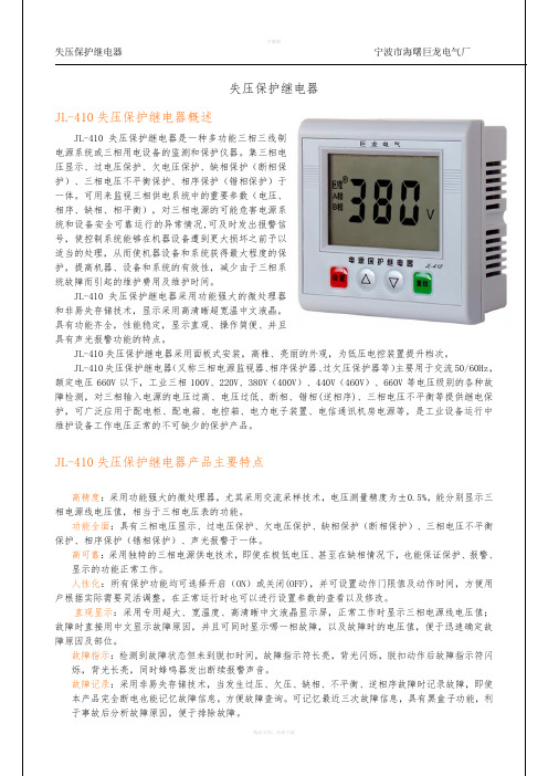
安装方式:采用96×96标准尺寸面板,方便用户施工安装。
复位方式:相序、缺相故障手动复位;不平衡、过欠压故障自动复位,也可按复位键手动复位。
断电后故障锁存功能。
JL-410失压保护继电器功能选型失压保护继电器按功能的组合分以下四个系列,每个系列都有不同电压等级的产品。
失压保护继电器不同电压等级的产品选型产品选型举例1.如用户需要全部保护功能(过电压保护、欠电压保护、缺相保护、三相电压不平衡保护、相序保护),使用于380V电压,那所选择的失压保护继电器产品型号,应该为JL-410。
2.如用户只需要相序保护,缺相保护两种功能,使用于煤矿660V的电压,那所选的失压保护继电器产品型号应该为JL-411-60。
JL-410失压保护继电器功能描述:1、过压保护:当电网电压大于设定值时启动该项保护功能,动作门限值设定范围OFF-390-490V,动作方式为定时限,动作时间设置范围0.1-25s。
保护动作后电网电压恢复到小于设定值10V以上时,保护器自动复位,也可按复位键手动复位。
用户可选择是否启用该项保护功能。
2、欠压保护:当电网电压小于设定值时启动该项保护功能,动作门限值设定范围300-370V-OFF,动作方式为定时限,动作时间设置范围0.1-25s。
保护动作后电网电压恢复到大于设定值10V以上时,保护器自动复位,也可按复位键手动复位。
用户可选择是否启用该项保护功能。
3、三相电压不平衡保护:当电网电压三相不平衡度大于设定值时启动该项保护功能,不平衡度动作门限值设定范围OFF-5-30%,动作方式为定时限,动作时间设置范围1-25s。
当电网电压三相不平衡度恢复到小于设定门限值2%以上时,保护器自动复位,也可按复位键手动复位。
用户可选择是否启用该项保护功能。
三相电压不平衡度计算公式:A ——电压不平衡度%100maxminmax⨯-=U UU Amax U ——三相线电压中最大线电压值min U ——三相线电压中最小线电压值4、缺相保护:当电网电压三相不平衡度大于30%时启动该项保护功能,动作时间1s 。
OLM技术参数
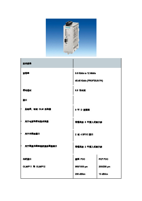
6GK1503-2CA00 SIMATIC NET, PB OLM/P11 V4.0 带有1 个RS485 和的光纤链路模块和1 塑料光纤接口(2 BFOC 插座),带信号接点和测量输出,包括2 个BFOC 连接器6GK1503-2CB00 SIMATIC NET, PB OLM/G11 V4.0 带有1 个RS485 和的光纤链路模块和1 玻璃光纤接口(2 BFOC 插座),带信号接点和测量输出6GK1503-2CC00 SIMATIC NET, PB OLM/G11-1300V4.0 带有1 个RS485 和的光纤链路模块和1 玻璃光纤接口(2 BFOC 插座),远距离时波长1300nm,带信号接点和测量输出6GK1503-3CA00SIMATIC NET, PB OLM/P12 V4.0 带有1 个RS485 和的光纤链路模块和2 塑料光纤接口(4 BFOC 插座),带信号接点和测量输出,包括4 个BFOC 连接器6GK1503-3CB00SIMATIC NET, PB OLM/G12 V4.0 带有1 个RS485 和的光纤链路模块和2 玻璃光纤接口(4 BFOC 插座),标准距离时达2850m,带信号接点和测量输出6GK1503-3CC00SIMATIC NET, PB OLM/G12-1300V4.0 带有1 个RS485 和的光纤链路模块和2 玻璃光纤接口(4 BFOC 插座),远距离时波长1300nm,带信号接点和测量输出6GK1503-3CD00 SIMATIC NET, PB OLM/G12-EEC V4.0 带有1 个RS485 和的光纤链路模块和2 玻璃光纤接口(4 BFOC 插座),扩展温度范围-20..+60 ℃6GK1503-2CA00 SIMATIC NET, PB OLM/P11 V4.0 带有1 个RS485 和的光纤链路模块和1 塑料光纤接口(2 BFOC 插座),带信号接点和测量输出,包括2 个BFOC 连接器。
电源设备的电磁兼容执行标准

电源设备的电磁兼容执行标准
电源设备的电磁兼容执行标准有以下几个:
1. IEC 61000系列:国际电工委员会(IEC)制定的一系列标准,包括IEC 61000-3-2(电源电流谐波)、IEC 61000-3-3(电源电压变化、波动和闪烁)、IEC 61000-6-1(一般环境)、IEC 61000-6-2(工业环境)等。
2. FCC Part 15:美国联邦通讯委员会(FCC)发布的关于电磁兼容的标准,主要适用于美国市场。
其中FCC Part 15B适用于家用电子设备,FCC Part 15C适用于无线电发射设备。
3. CISPR 22:国际特种委员会电磁兼容标准,主要适用于信息技术设备。
CISPR 22的电磁辐射和抗扰度要求与FCC Part 15B类似。
4. EN 55032:欧洲标准化组织(CENELEC)发布的电磁兼容标准,适用于信息技术设备。
EN 55032的电磁辐射和抗扰度要求与CISPR 22类似。
5. GB/T 17626系列:中国国家标准化管理委员会发布的电磁兼容标准,包括GB/T 1762
6.2(工业、科学和医疗设备)、GB/T 17626.3(信息技术设备)等。
需要注意的是,电源设备可能还需要符合其他特定的标准,如安全标准(如IEC 60950-1)等。
具体的执行标准要根据具体的电源设备和市场要求来确定。
- 1、下载文档前请自行甄别文档内容的完整性,平台不提供额外的编辑、内容补充、找答案等附加服务。
- 2、"仅部分预览"的文档,不可在线预览部分如存在完整性等问题,可反馈申请退款(可完整预览的文档不适用该条件!)。
- 3、如文档侵犯您的权益,请联系客服反馈,我们会尽快为您处理(人工客服工作时间:9:00-18:30)。
EMC TEST REPORTEMC TEST REPORTSBC83810.A2TEST RESULT : PASSDATE OF TEST: 20,Nov,2004PREPARE BY:AXIOMTEK CO., LTD.9F, NO.2, LANE 235, PAO CHIAO ROADHSIN TIEN, TAIPEI HSIEN, TAIWAN, R.O.C.TEL : 886-2-2917-4550FAX : 886-2-2917-3200Approved : Edison Tested : YiyingEMC TEST REPORTCONTENTSDECLARATION OF CONFORMITY (1)CONTENTS (2)LIST OF TABLE (3)1.GENERAL INFORMATION (4)1.1D ESCRIPTION OF THE TESTED SAMPLES (4)1.1.1Rating and Physical Characteristics (4)1.1.2Sources of interference (4)1.2TEST FACTILITY (5)1.2.1 1. ( EMI SITE) (5)1.2.2 1. ( EMS SITE) (5)1.3DESCRIPTION OF THE SUPPORT EQUIPMENTS (5)2.MEASUREMENT CONDITIONS (7)2.1M ODES OF O PERATION (7)2.2L IST OF T EST AND M EASUREMENT I NSTRUMENTS (7)3.TEST RESULTS (8)3.1C ONTINUOUS I NTERFERENCES (8)3.1.1Conducted Emission ( AC Power line) (8)3.1.2Disturbances in telecommunication (9)3.1.3Radiated Emission (10)3.1.4Harmonics (11)3.1.5Voltage fluctuations (12)3.1.6Electrostatic Discharge (12)3.1.7Radio-frequency electromagnetic field (14)3.1.8Electrical Fast transients common mode (15)3.1.9Surge immunity test (16)3.1.10Conducted disturbances Induced by Radio-frequency Field immunity (17)3.1.11Power Frequency Magnetic Field immunity (18)3.1.12Voltage Dips and Voltage Interruption Immunity (19)Page: 2 of 19EMC TEST REPORTPage: 3 of 19LIST OF TABLETABLE 1 LIST OF TEST AND MEASUREMENT EQUIPMENT .....................................................................................................7 TABLE 2 TEST RESULT OF CONDUCTED EMISSION , AC POWERLINE............................................................................8 TABLE 3 CONDUCTED EMMISSION , AC MAINS ; 0.15 - 30 MH Z.............................................................................................9 T ABLE 4 DISTUBANCES IN TELECOMMUNICATION ; 0.15 - 30 MH Z; LAN .............................................................................9 TABLE 5 TEST RESULT OF RADIATED EMMISSION .........................................................................................................10 TABLE 6 RADIATED EMMISSION , MAINS ; 30 - 1000 MH Z...................................................................................................11 TABEL 7 DIRECT APPLICATION OF DISCHARGE ..................................................................................................................13 TABLE 8 RADIO – FREQUENCY ELECTROMAGNETIC FILED ; 80 –1000 MH Z.......................................................................14 TABLE 9 FAST TRANSIENTS COMMON MODE ......................................................................................................................15 TABLE 10 TEST RECORD OF SURGE IMMUNITY ...................................................................................................................16 TABLE 11 TEST RECORD OF POWER FREQENCY MAGNETIC FIRELD IMMUNITY ..................................................................18 TABLE 12 TEST RECORD OF VOLTAGE INTERRUPTION .......................................................................................................19 TABLE 13 TEST RECORD OF VOLTAGE DIPS (19)EMC TEST REPORTPage: 4 of 191. GENERAL INFORMATION1.1 DESCRIPTION OF THE TESTED SAMPLESThe tested sample is an Industrial PC for general use in Light Industry Environment. Thesamples was tested with the following configuration:Component:Manufacturer: Model No.: ChassisAXIOMTEK EM60320A Single Board ComputerAXIOMTEKSBC83810VGA-A2 SBC83810VEA-A1CPU INTEL P-M-1.3GHz(100*13) RAM DDR-RAM 256MByteSlot PlaneAXIOMTEK N/ASwitching Power SupplyFSPFSP180-50PLA1(180W)1.1.1 Rating and Physical CharacteristicsInput Voltage: 115/230VACFrequency: 50/60Hz Rated Power: 10.0/5.0A Protection Class: Class I1.1.2 Sources of interference1. Switching frequency of Power Supply:2. Pulses on clock or other lines of CPU card or peripheral cards (access. Equip During testing)EMC TEST REPORT 1.2 TEST FACTILITY1.2.1 1. ( EMI SITE)SPORTON International Inc.No. 3, Lane 238, Kang Lo Street, Nei Hwu District,Taipei 11424, Taiwan, R.O.C.Test Site No : C001-NH, OS01-NH1.2.2 1. ( EMS SITE)SPORTON International Inc.No. 52, Hwa Ya 1st Rd., Hwa Ya Technology Park,Kwei-Shan Hsiag, Tao Yuan Hsien, Taiwan, R.O.C.1.3 DESCRIPTION OF THE SUPPORT EQUIPMENTSSUPPORT UNIT 1. ---PS/2 KEYBOARD( HP)Model No .: KB-0133Data Cable: Shielded, 360 degree via metal backshells, 1.9mFCC ID : DOCSUPPORT UNIT 2. ---MONITOR (SONY)Model No.: GDM-17SE2TPower Supply Type: SwitchingPower Cord: Non-ShieldedData Cable: Shielded,360 degree via metal backshells,1.7mFCC ID : AK8GDM17SE2TSUPPORT UNIT 3. ---MODEM (ACCEEX)Model No.: DM1414Power Supply Type: Linear, AC AdapterPower Cord: Non-shieldedData Cable: Shielded, 360 degree via metal backshells, 1.15mFCC ID : IFAXDM1414SUPPORT UNIT 4. ---PS/2 MOUSE (HP)Model No. : M-S69Data Cable: Non-shielded,1.7 mFCC ID : JNZ211443SUPPORT UNIT 5. ---Printer (HEWLETT PACKARD)Model No.: DESK JET 400Power Supply Type: LinearPower Cord: Non-shieldedData Cable: Shielded, 360 degree via metal backshells, 1.35mFCC ID : B94C2462XPage: 5 of 19EMC TEST REPORT SUPPORT UNIT 6. ---USB KEYBOARD (BTC)Model No. : 7932Data Cable: Non-shielded,1.6 mFCC ID : E5XKBUCP10410SUPPORT UNIT 7. ---Personal Computer - for remote workstationPower Supply TYPE: SwitchingPower Cord : Non ShieldedT/P Cable: Non shielded 10 mRemark : This support device was tested to comply with FCC standards andAuthorized under a declaration of conformityPage: 6 of 19EMC TEST REPORTPage: 7 of 192. MEASUREMENT CONDITIONS 2.1 MODES OF OPERATIONIndependent modes of operation are:Operating the Industrial PC with monitor & modem & keyboard & mouse. The Industrial PC run EMI test program under Windows 2000 The VGA Card display output 1600x1200 94K/75Hz resolutionAt same time "TP TEST.BAT" was executed to link with remote workstation to receive and transmit data by T/P line.2.2 LIST OF TEST AND MEASUREMENT INSTRUMENTSTABLE 1 LIST OF TEST AND MEASUREMENT EQUIPMENTFor EMI Test:InstrumentManufacturerModel No.Serial No.CharacteristicsCalibration DateRemarkTest ReceiverHP 8591EM 3801A013259 KHz-30MHz Mar.27.2003 Conduction LISN EMCO 3810/2 9703-183850uH / 50 ohm May.05.2003 Conduction LISN KYORITSU KNW – 4078-1010-15 50uH / 50 ohmDec.03.2002Conduction Power FilterCORCOM MR12030N/A 30Ax2 N/A Conduction ImpedanceStabilization Network SCHAFFNERISNT40016849150KHz – 230KHzJun.20.2003ConductionTelecommunication PortSpectrum AnalyzerADVANTESTR3261C 71720471 9KHz-2.6 GHz Jan.16.2003Radiation Amplifier HP 8447D 2944A062920.1 MHz-1.3 GHz Mar.03.2003 Radiation Bilog Antenna CHASE CBL6112A 2118 30 MHz-2 GHz Jun.25.2003 Radiation Half-wave dipoleAntenna EMCO3121C8912-128520 MHz -1 GHzMay.15.2003RadiationTurn tableEMCO 2080 9508-18050~360 degree N/A Radiation Antenna MastEMCO20759804-21511MHz-4MHzN/ARadiationController EMCO 2090 9804-1328N/A N/ARadiationCalibration interval of instruments listed above is one yearEMC TEST REPORT3. TEST RESULTSResult: PASS3.1 CONTINUOUS INTERFERENCES3.1.1 Conducted Emission ( AC Power line)Port : AC MainsBasic Standard : EN 55 022:1998Frequency Range : 0.15-30MHzLimits : Clause 9, Table 2 (Class A)Result: PASSTest SetupInput Voltage: 230VAC/50HzOperational mode: ONEarthling:If the result of the measurement with the Quasi Peak detector is below theAverage limit the measurement with Average detector can be omitted.Disturbances other than those mentioned are small or not detectable.TABLE 2 TEST RESULT OF CONDUCTED EMISSION, AC POWERLINESettingsFrequency Setting Start Stop Step Size IF Bandwidth Detector Meas. Time0.15MHz 30MHz 9KHz Peak 20msFerquency LINE / Level Over Line Limit Line Read Level Insertion Cable Detect Mode (MHz) NEUTRAL (dBmV)(dB) (dBuV) (dBmV)Loss (dB) Loss (dB)( QP or AV )Corrected Reading : Insertion Loss + Cable Loss + Read Level = LevelLimit Line – Level =Over LinePage: 8 of 19EMC TEST REPORT TABLE 3 CONDUCTED EMMISSION, AC MAINS ; 0.15 - 30 MHZ3.1.2 Disturbances in telecommunicationTABLE 4 DISTUBANCES IN TELECOMMUNICATION ; 0.15 - 30 MHZ; LANCorrected Reading : Limits – Meter Reading = MarginPage: 9 of 19EMC TEST REPORT3.1.3 Radiated EmissionPort : AC MainsBasic Standard : EN 55 022:1998Frequency Range : 30-1000MHzLimits : Clause 10,Table 4 ( Class A )Result: PASSTest SetupInput Voltage: AC 230V/50HzOperational mode: ONMeasurement Delay : 10.0 secondsPst Integration Time : 10 minutesPst Integration Periods : 1Earthling:If the result of the measurement with the Quasi Peak detector is below theAverage limit themeasurement with Average detector can be omitted.Disturbances other than those mentioned are small or not detectable.TABLE 5 TEST RESULT OF RADIATED EMMISSIONSettingsFrequency Setting Start Stop Step Size IF Bandwidth Detector Meas. Time30MHz 1GHz 120KHz Peak 20msFrequency Polarity Over Limit Reading Antenna Cable PreampLevel Limit Line Level Factor Loss Factor(MHz) (dBuV/m)(dB)(dBuV/m)(dB/uV)(dB/m) (dB) (dB)Corrected Reading :Antenna Factor + Cable Loss + Read Level – Preamp Factor = LevelLimits Line – Level = Over LimitPage: 10 of 19EMC TEST REPORTTABLE 6 RADIATED EMMISSION, MAINS; 30 - 1000 MHZ1280*1024 80K 75HZ3.1.4 HarmonicsPort : MainsBasic Standard IEC 61 000-3-2:1995/A12: 1996/A13:1997/A1:1998/A2:1998/A14:2000Product Standard: EN61000-6-2:2001Limits : EN 61 000-3-2Result: PASSTest SetupInput Voltage : 230VAC/50HzOperational mode : ONDevice Class : DCurrent Measurement Range : HighMeasurement Delay : 10.0 secondsTest Duration : 2.0 minutesClass Determination : 10.0 secondsFundamental Current : 0.226 AReal Power : 57.6WPower Factor : 0.486Percent in Envelope : 100.0%Page: 11 of 19EMC TEST REPORTPage: 12 of 193.1.5 Voltage fluctuationsPort : MainsBasic Standard : IEC 61 000-3-3: 1995/A1:2001 Product Standard: EN61000-6-2:2001 Limits : EN 61 000-3-3Result: PASSThe power consumption of the PC is continuous, therefore no voltage fluctuations are generated.Pst Pst Dc (%) Dmax (%) Dt (%) Reading 0.070 0.00 0.00 0.00 0.00 Limit 0.65 1.0 3.0 4.0 3.03.1.6 Electrostatic DischargePort : EnclosureBasic Standard : IEC 61 000-4-2: 1995/A1:1998 Product Standard: EN61000-6-2:2001 Performance Criteria: ATest Specification: EN 50 024: 1998Voltage: ±2 / ±4 / ±8KV (For Air Discharge) ±2 / ±4KV (For Contact Discharge) Result: PASSTest SetupInput Voltage: 230VAC/50Hz Operational mode: ONEarthling: Through Power Cord Temperature: 29 Relative Humidity: 55%EMC TEST REPORTPage: 13 of 19TABEL 7 DIRECT APPLICATION OF DISCHARGETESTPOINT VOLTAGE TEST NO. OBSERVATION RESULTSCREW ±2 / ±4 / ±8By Air 10 / By Con.25Normal PASS LAN CONNECTOR ±2 / ±4 / ±8By Air 10 / By Con.25Normal PASS VGA CONNECTOR ±2 / ±4 / ±8By Air 10 / By Con.25Normal PASS COM PORT ±2 / ±4 / ±8By Air 10 / By Con.25Normal PASS AC SOCKETS ±2 / ±4 / ±8By Air 10 / By Con.25Normal PASS PRINT PORT ±2 / ±4 / ±8By Air 10 / By Con.25Normal PASS PS/2 KEYBOARD PORT ±2 / ±4 / ±8By Air 10 / By Con.25Normal PASS PS/2 MOUSE PORT ±2 / ±4 / ±8By Air 10 / By Con.25Normal PASS USB PORT ±2 / ±4 / ±8By Air 10 / By Con.25Normal PASS AUDIO PORT ±2 / ±4 / ±8By Air 10 / By Con.25Normal PASS POWER SWITCH ±2 / ±4 / ±8By Air 10 / By Con.25Normal PASSEMC TEST REPORTPage: 14 of 193.1.7 Radio-frequency electromagnetic fieldPort : EnclosureBasic Standard : IEC 61 000-4-3: 1995/A1:1998 Product Standard: EN61000-6-2:2001 Performance Criteria: ATest Specification: EN 50 024: 1998 Frequency. Range.: 80 - 1000MHZField Strength 3 V/m (Modulated 80% AM)Result:PASSTest SetupInput Voltage: 230VAC/50Hz Operational mode: ONEarthling: through power cordTABLE 8 RADIO – FREQUENCY ELECTROMAGNETIC FILED; 80 –1000 MHZ SettingsFrequency Setting Start Stop Field Strength Sweep ModeMeas. Time80MHz 1000MHz 3V/m Auto 200msNo abnormalities observed.EMC TEST REPORTPage: 15 of 193.1.8 Electrical Fast transients common modePort : Mains PlugBasic Standard : IEC 61 000-4-4: 1995 Product Standard: EN61000-6-2:2001 Performance Criteria: ATest Specification: EN 50 024:1998TEST Voltage: On Power Supply — ±0,5 / ±1.0KVOn I/O Signal, data and control line ±0.25 / ±0.5KVRep. frequency : 5kHzResult: PASSTest SetupInput Voltage: 230VAC/50Hz Operational mode: ONEarthling: through power cord Temperature: 29 Relative Humidity: 55%Coupling : Coupling NetworkTABLE 9 FAST TRANSIENTS COMMON MODETESTPOINT PolarityOBSERVATION RESULT L1 ± Normal Function PASS L2 ± Normal Function PASSL3 ± Normal FunctionPASSEMC TEST REPORT3.1.9 Surge immunity testBasic Standard : IEC 61 000-4-5: 1995Product Standard: EN61000-6-2:2001Performance Criteria: BTest Specification: EN 50 024:1998TEST Voltage: On I/O Signal, data and control line - ± 1.0 KVOn Power Supply - ±1.0KV / ±2.0KVResult: PASSTest SetupInput Voltage: 230VAC/50HzOperational mode: ONEarthling: through power cordTemperature: 29Relative Humidity: 55%Remark : The test on I/O Signal, data and control line is not required due toNormal functioning cannot be achieved because of the impact of the CDN onThe EUTTABLE 10 TEST RECORD OF SURGE IMMUNITYPhase Angle Test Voltage (KV) Test Location Polarity 0 90 180 270 Result1 KV L – N B B B B PASSB B B BL – PE B B B B PASS 2 KV B B B BN - PE B B B B PASSB B B BRemark : PE = DC output GNDPage: 16 of 19EMC TEST REPORT 3.1.10 Conducted disturbances Induced by Radio-frequency Field immunityBasic Standard : IEC 61 000-4-6: 1996Product Standard: EN61000-6-2:2001Performance Criteria: ATest Specification: EN 50 024:1998TEST Voltage: 3 V/rms (Modulated 1KV 80% AM)TEST Port: on Input AC power port and signalFrequency Rang: 0.15 MHz to 80 MHzResult: PASSTest SetupInput Voltage: 230VAC/50HzOperational mode: ONEarthling: through power cordTemperature: 29Relative Humidity: 55%Test Mode LAN : 1000M / 100MCoupling : Coupling NetworkPage: 17 of 19EMC TEST REPORTPage: 18 of 193.1.11 Power Frequency Magnetic Field immunityBasic Standard : IEC 61 000-4-8: 1993 Product Standard: EN61000-6-2:2001 Performance Criteria: ATest Specification: EN 50 024:1998Result:PASSTest SetupInput Voltage: 230VAC/50Hz Operational mode: ONEarthling: through power cord Temperature: 29 Relative Humidity: 55%Test Mode LAN : 1000M / 100M Coupling : Coupling NetworkTABLE 11 TEST RECORD OF POWER FREQENCY MAGNETIC FIRELD IMMUNITYPower Frequency Testing duration Coil Results Remark Magnetic Field Orientation 50Hz,1A/m 1.0min X-axis PASS Normal 50Hz,1A/m 1.0min Y-axis PASS Normal 50Hz,1A/m 1.0min Z-axis PASS NormalEMC TEST REPORTPage: 19 of 193.1.12 Voltage Dips and Voltage Interruption ImmunityBasic Standard : IEC 61 000-4-11: 1994 Product Standard: EN61000-6-2:2001Pass Performance Criteria: C for voltage interrupt, A for voltage dips Test Specification: EN 50 024:1998Result: PASSTest SetupInput Voltage: 230VAC/50Hz Operational mode: ON Temperature: 25 Relative Humidity: 55%Test Mode LAN : 1000M / 100M Coupling : Coupling Network TEST of interval: 10secLevel and duration : Sequency of 3 dips/interrupt Voltage rise (and fail) time 1 ~ 5 usTABLE 12 TEST RECORD OF VOLTAGE INTERRUPTIONVoltage Phase Angle %Reduction Periods (s)Observation (v) 0 180 230 C C >95% 250 When testing, the power of theEUT must be reset by the operatorTABLE 13 TEST RECORD OF VOLTAGE DIPSVoltage Phase Angle %Reduction Periods (s) Observation(v) 0 180 230 C C 30 25 Normal 230 A A >95% 0.5Normal。
