BTRS-9780-1590-SPG中文资料
1590A中文资料

1590A Paired - Category 5e Unbonded-Pair CableFor more information pleasecall1-800-Belden1See Put-ups and ColorsRelated Documents : No. 8 forDataTwist Cables (ModifiedWestern Electric).pdf Description:24 AWG solid bare copper conductors, plenum, FEP Teflon® insulation, twisted pairs, rip cord, see color code chart (below), Flamarrest®jacket (natural or blue).SUITABLE APPLICATIONS:Suitable Applications Premise Horizontal Cable, Gigabit Ethernet, 100BaseTX, 100BaseVG ANYLAN,155ATM, 622ATM, NTSC/PAL Component or Composite Video, AES/EBU,Digital Video, RS-422PHYSICAL CHARACTERISTICS:CONDUCTOR:Number of Pairs 2Total Number of Conductors 4AWG24Stranding SolidConductor Material BC - Bare CopperINSULATION:Insulation Material FEP - Fluorinated Ethylene PropylenePair Color Code Chart :Number Color1White/Blue Stripe & Blue Number Color2White/Orange Stripe & OrangeOUTER SHIELD:Outer Shield Material UnshieldedOUTER JACKET:Outer Jacket Material Trade Name Flamarrest®Outer Jacket Material LS PVC - Low Smoke Polyvinyl Chloride Outer Jacket Ripcord YesOVERALL NOMINAL DIAMETER:Overall Nominal Diameter.165 in.1590A Paired - Category 5e Unbonded-Pair CableMECHANICAL CHARACTERISTICS:Operating Temperature Range-20°C To +75°CBulk Cable Weight21 lbs/1000 ft.Max. Recommended Pulling Tension13 lbs.Min. Bend Radius (Install)0.7 in.APPLICABLE SPECIFICATIONS AND AGENCY COMPLIANCE:APPLICABLE STANDARDS:NEC/(UL) Specification CMP, UL444CEC/C(UL) Specification CMPEU CE Mark (Y/N)YesEU RoHS Compliant (Y/N)YesEU RoHS Compliance Date (mm/dd/yyyy):01/01/2005TIA/EIA Specification568-B.2 Category 5eOther Specification NEMA WC-63.1 Category 5e, UL verified to Category 5eFLAME TEST:UL Flame Test NFPA 262CSA Flame Test FT4, FT6PLENUM/NON-PLENUM:Plenum (Y/N)YNon-Plenum Number1588A, 1588RELECTRICAL CHARACTERISTICS:Nom. Mutual Capacitance @ 1 KHz14 pF/ftMaximum Capacitance Unbalance (pF/100 m)330 pF/100 mNominal Velocity of Propagation72 %Maximum Delay (ns/100 m)538 @ 100MHz ns/100 mMaximum Delay Skew (ns/100m)45 ns/100 mMaximum Conductor DC Resistance @ 20 Deg. C9.38 Ohms/100 mMaximum DCR Unbalance @ 20 Deg. C 5 %Max. Operating Voltage - UL300 V RMSELECTRICAL CHARACTERISTICS - PREMISE:Premise Cable Electricals Table 1 :1590A Paired - Category 5e Unbonded-Pair CableFrequency (MHz)Max.Attenuation(dB/100 m)Min. NEXT(dB)Min. PSNEXT(dB)Min. ACR (dB)Min. PSACR(dB)Min. ReturnLoss (dB)Min.StructuralReturn Loss(dB)1 2.065.362.363.060.320.023.0 4 4.156.353.351.049.223.023.0 8 5.851.848.846.043.024.524.5 10 6.550.347.343.040.825.025.0 168.247.344.339.036.025.025.0 209.345.842.836.533.525.025.0 2510.444.341.333.930.924.324.3 31.2511.742.939.931.028.223.623.6 62.517.038.435.422.019.021.521.5 10022.035.332.314.010.320.120.1 15528.132.529.5 4.4 1.415.820032.030.827.8 4.0 1.015.0Premise Cable Electricals Table 2 :Frequency (MHz)Input (Unfitted)Impedance (Ohms)Fitted Impedance(Ohms)Min. ELFEXT (dB)Min. PSELFEXT (dB)1100 ± 15100 ± 1563.860.84100 ± 15100 ± 1551.748.78100 ± 15100 ± 1545.742.710100 ± 15100 ± 1543.840.816100 ± 15100 ± 1539.736.720100 ± 15100 ± 1537.734.725100 ± 15100 ± 1535.832.831.25100 ± 15100 ± 1533.930.962.5100 ± 15100 ± 1527.824.9100100 ± 15100 ± 1523.820.8155100 ± 25100 ± 1519.916.9200100 ± 25100 ± 1517.714.7NOTES:Notes Jacket sequentially marked at 2 ft. intervals. Third party verified to TIA/EIA-568-B.2, Category 5e.PUT-UPS AND COLORS:Item Description Put-Up (ft.)Ship Weight (lbs.)Jacket Color Notes1590A 8771000 2 PR #24 FEPFLMRST1000 16NATURAL C1590A D151000 2 PR #24 FEPFLMRST1000 16BLUEC = CRATE REEL PUT-UP.Revision Number: 2 Revision Date: 04-18-20061590A Paired - Category 5e Unbonded-Pair Cable© Copyright 2006 Belden, IncAll Rights Reserved.Although Belden ("Belden") makes every reasonable effort to ensure their accuracy at the time of this publication, information and specifications described herein are subject to error or omission and to change without notice, and the listing of such information and specifications does not ensure product availability.Belden provides the information and specifications herein on an "AS IS" basis, with no representations or warranties, whether express, statutory or implied. In no event will Belden be liable for any damages (including consequential, indirect, incidental, special, punitive, or exemplary damages) whatsoever, even if Belden has been advised of the possibility of such damages, whether in an action under contract, negligence or any other theory, arising out of or in connection with the use, or inability to use, the information or specifications described herein.All sales of Belden products are subject to Belden's standard terms and conditions of sale.Belden believes this product to be in compliance with the following environmental regulations: California Proposition 65 Consent Judgment For Wire & Cable Mfgs.(San Francisco Superior Court Nos. 312962 And 320342); EU RoHS (Directive 2002/95/EC, 27-Jan-2003);Material manufactured prior to the compliance date may still be in stock at Belden facilities and in our Distributor's inventory. EUELV (Directive 2000/53/EC, 18-Sept-2000); EU WEEE (Directive 2002/96/EC, 27-Jan-2003); And EU BFR (Directive 2003/11/EC, 6-Feb-2003). The information provided in this Product Disclosure, and the identification of materials listed as reportable or restricted within the Product Disclosure, is correct to the best of Belden's knowledge, information and belief at the date of its publication. The information provided in the Product Disclosure is designed only as a general guide for the safe handling, storage, and any other operation of the product itself or the one that it becomes a part of. This Product Disclosure is not to be considered a warranty or quality specification. Regulatory information is for guidance purposes only. Product users are responsible for determining the applicability of legislation and regulationsbased on their individual usage of the product.Belden declares this product to be in compliance with EU LVD (Low Voltage Directive 73/23/EEC), as amended by directive 93/68/EEC.。
高隔离电压的大功率IGBT驱动芯片TX-KE106产品手册

高隔离电压的大功率IGBT驱动芯片TX-KE106产品手册目录一、概述 (3)二、原理框图 (3)三、电气参数 (3)3.1 极限参数 (3)3.2 驱动特性 (4)3.3 工作条件 (5)3.4 短路保护特性 (5)3.5 对驱动电源Vp要求 (6)四、波形图 (6)4.1 正常驱动波形图 (6)4.2 保护波形图 (6)4.3 说明 (6)五、尺寸结构 (7)5.1 外形尺寸 (7)5.2 管脚说明 (7)六、应用电路说明 (7)6.1 驱动器低压信号侧的连接说明 (7)6.1.1 逻辑电路输入电源Vdd (8)6.1.2 输入信号PWM (8)6.1.3 报警信号/Fault (8)6.1.4 复位信号Reset (8)6.2 与外部驱动电源的连接 (8)6.3 驱动器高压侧的输出连接 (8)6.3.1 驱动器输出功率的计算 (8)6.3.2 与IGBT的连接 (8)6.4 保护参数的设置 (9)6.4.1 短路保护阈值Vn的设置 (9)6.4.2 保护盲区Tblind的设置 (9)6.4.3 软关断时间Tsoft的设置 (9)6.5 驱动芯片测试方法 (10)6.6 典型应用连接图 (10)七、相关产品信息 (10)7.1 TX-PD106(DC-DC高隔离模块电源) (10)7.2 TX-DE106D2 IGBT驱动板 (10)八、常见问题 (11)九、其它说明 (11)TX-KE106 高隔离电压、大电流IGBT驱动器一、概述∙高隔离电压IGBT驱动器,可驱动电压≤4500V的全系列IGBT。
∙输出电流40A,输出电荷40μC,输出功率4.5W。
∙变压器调制模式传递PWM信号。
∙短脉冲抑制功能。
∙工作占空比0-100%。
∙关断时输出为负电平。
∙IGBT的栅极充电和放电速度可分别调节。
∙短路软关断保护,并报警输出。
∙绝缘电压7000V。
二、原理框图三、电气参数3.2 驱动特性除另有指定外,均为在以下条件时测得:Ta=25℃,Vdd=5V,Vp=24V,Fop=30KHz四、波形图4.1 正常驱动波形图4.2 保护波形图4.3 说明工作时,由输入端串入的很窄的正负脉冲均被抑制,提高抗干扰性。
BT-SGMWJ 06139-2016 旧标准收集 保存

车门外水切技术要求Technical requirements for Side Door Outer Belt Weatherstrip2016-05-19发布2016-05-19实施上汽通用五菱汽车股份有限公司发布前言本标准由上汽通用五菱汽车股份有限公司技术中心提出并负责起草。
本标准由上汽通用五菱汽车股份有限公司技术中心归口。
本标准主要起草人:谭柳、余辉、莫记燕、柯娟、成淑仪、韦思意、王丽敏、曹德乐、何丹丹本标准为首次发布。
车门外水切技术要求1 范围本标准规定了汽车车门外水切的技术要求及测试方法。
本标准适用于SGMW生产车辆的车门外水切。
2 规范性引用文件下列文件对于本文件的应用是必不可少的。
凡是注日期的引用文件,仅所注日期的版本适用于本文件。
凡是不注日期的引用文件,其最新版本(包括所有的修改单)适用于本文件。
GB/T 223.72-2008 钢铁及合金硫含量的测定重量法GB/T 228.1-2010 金属材料拉伸试验第1部分:室温试验方法GB/T 528-2009硫化橡胶或热塑性橡胶拉伸应力应变性能的测定GB/T 529-2008硫化橡胶或热塑性橡胶撕裂强度的测定(裤形、直角形和新月形试样)GB/T 531.1-2008 硫化橡胶或热塑性橡胶压入硬度试验方法第1部分:邵氏硬度计法(邵尔硬度)GB/T 1033.1-2008塑料.非泡沫塑料密度的测定.第1部分:浸渍法、液体比重瓶法和滴定法GB/T 1040.1-2006塑料拉伸性能的测定第1部分:总则GB/T 2411-2008 塑料和硬橡胶使用硬度计测定压痕硬度(邵氏硬度)GB/T 2917.1-2002 以氯乙烯均聚和共聚物为主的共混物及制品在高温时放出氯化氢和任何其它酸性产物的测定刚果红法GB/T 2941-2006橡胶物理试验方法试样制备和调节通用程序GB/T 3512-2014硫化橡胶或热塑性橡胶热空气加速老化和耐热试验GB/T 4340.1-2009金属材料维氏硬度试验第1部分: 试验方法GB/T 5470-2008塑料冲击法脆化温度的测定GB/T 7141-2008塑料热老化试验方法GB/T 7759.1-2015 硫化橡胶或热塑性橡胶压缩永久变形的测定第1部分:在常温及高温条件下GB/T 7762-2014 硫化橡胶或热塑性橡胶耐臭氧龟裂静态拉伸试验GB/T 9286-1998色漆和清漆漆膜的划格试验GB/T 15256-2014 硫化橡胶或热塑性橡胶低温脆性的测定(多试样法)GB/T 16422.2-2014塑料实验室光源暴露试验方法第2部分:氙弧灯GB/T 19243-2003 硫化橡胶或热塑性橡胶与有机材料接触污染的试验方法GB/T 21282-2007乘用车用橡塑密封条QC/T 639-2004 汽车用橡胶密封条QC/T 709-2004汽车密封条压缩永久变形试验方法QC/T 716-2004汽车密封条保持力和插入力试验方法GMW 14650-2015 外饰塑料件的性能要求(Performance Requirements for Exterior Plastic Parts - Issue 12)GMW 15726-2015 密封条涂层厚度测量(Coating Thickness Measurements for Weatherstrips -Issue 3)GMW 16774-2012 密封条植绒附着测试(Flock Adhesion Tests for Weatherstrips Issue 1) SAE J 2527 用受辐射氙弧装置加速照射汽车外部材料的性能标准(Performance Based Standard for Accelerated Exposure of Automotive Exterior Materials Using A Controlled Irradiance Xenon~Arc Apparatus)3 术语及定义下列术语和定义适用于本文件。
Sprecher + Schuh 联系器产品目录说明书

C on t a c t o r sContactors – General Purpose and Definite PurposeA rugged andcomprehensive range of contactors from 5 to 900 HPSprecher + Schuh’s broad line of general purpose contactors combine perfor-mance and reliability in space saving designs that are well proven and used the world over. Sprecher + Schuh’s IEC design is dimensionally among the smallest devices in the industry. A range of definite purpose contactors is also available, providing reliable and economic performance in commercial applications.Economy and selectionFour different contactor families provide a wide variety of contactor sizes, one for practically every horsepower increment! The ability to select intermediate sizes assures a closer match for your motor and provides economy not found with traditionally sized devices. Definite pur-pose contactors are available in one, two, three and four pole, up to 90A.Precisely match thecontactor to the applicationUnique to IEC-style contactors is the ability to select the exact device required for a specific application. By identify-ing the conditions under which the contactor will be used, i.e., resistive loads, reversing, inching and plugging, etc., published “life-curve” data predicts contact life in millions of operations. This information enables you to select the precise contactor for your applica-tion… without buying too much or too little.Designed for long lifeDestructive electrical arcs are com-mon when opening or “breaking” the contacts of larger contactors. Sprecher + Schuh general purpose contactors are designed to dramatically reduce electri-cal arcing by quickly guiding the arc off of the contacts and into specially de-signed “arc chutes.” This special design divides and eliminates the electrical arcs quickly, significantly increasing contact life and assuring reliable operation.Limitless choicesA comprehensive selection of modular accessories is available for all contactor families, which allows infinite contactor and starter combinations, both open and enclosed.Safety in mind…Virtually all Sprecher + Schuhcontactors are designed to be safe from accidental contact with the finger or back-of-hand. On the smaller contactors, terminals and set screws are recessed, while larger devices (up to Series CA9) accept terminal covers that provideprotection according to VDE 0106, Part 100.Manufactured to rigorous quality standardsSprecher + Schuh contactors are de-signed and manufactured in plants that maintain quality certification to the rigorous international standards, ISO 9001. Sprecher + Schuh manufacturing facilities renew ISO certification every three years by passing an exacting qual-ity assurance audit.International standards and approvalsAll Sprecher+Schuh IEC contactors are cULus CSA Approved, along with sev-eral other certifications. They also carry the CE Mark and meet IEC 60947-1 requirements. They are approved in virtually every international market.Sprecher+Schuh IEC contactors are designed and manufactured in plants that are quality certified to international standard ISO 9001AC o n t a c t o r sC o n t a c t o r sThe information in this chart was derived from Table 50.1 of UL standard 508A. The voltages listed are rated motor voltages. The currents listed shall be permitted for system voltage ranges of 110-120, 220-240, 380-415, 440-480 and 550-600 volts.The full-load current values are for motors running at usual speeds and motors with normal torque characteristics. Motors built for especially low speeds or high torques may have higher full-load currents, andmulti-speed motors will have full-load currents varying with speed. In these cases, the nameplate current ratings shall be used.Caution: The actual motor amps may be higher or lower than theaverage values listed above. For more reliable motor protection, usethe actual motor current as listed on the motor nameplate. Use thistable as a guide only.AC o n t a c t o r s➊“EI” designation indicates coil has electronic interface capability with a PLC.C o n t a c t o r sAC o n t a c t o r sTable 139.1 – Rating Codes for AC Control-Circuit Contacts at 50 and 60 Hz ➍Table 139.2 – Rating Codes for DC Control-Circuit Contacts ➍Contact RatingCode Designation ➊Thermalcontinuous test current AmperesMaximum current, amperes ➋Maximum volt-Amperes120 Volt240 Volt480 Volt600 VoltMake Break Make Break Make Break Make Break Make Break A1501060 6.00~~~~~~7200720A3001060 6.0030 3.00~~~~7200720A6001060 6.0030 3.0015 1.5012 1.207200720B150530 3.00~~~~~~3600360B300530 3.0015 1.50~~~~3600360B600530 3.0015 1.507.500.7560.603600360C150 2.515 1.5~~~~~~1800180C300 2.515 1.57.50.75~~~~1800180C600 2.515 1.57.50.75 3.750.375 3.000.301800180D150 1.0 3.600.60~~~~~~43272D300 1.0 3.600.60 1.800.30~~~~43272E1500.51.800.30~~~~~~21636Contact RatingCode Designation ➊Thermal continuous test current AamperesMaximum make or break current, Amperes ➌Maximum make or break volt-Amperes at 300 volts or less125 Volt 250 Volt 301 to 600 VoltN15010 2.2~~275N30010 2.2 1.1~275N60010 2.2 1.10.40275P150 5.0 1.1~~138P300 5.0 1.10.55~138P600 5.0 1.10.550.20138Q150 2.50.55~~69Q300 2.50.550.27~69Q600 2.50.550.270.1069R150 1.00.22~~28R3001.00.220.11~28➊ The numerical suffix designates the maximum voltage design values, which are to be 600, 300, and 150 volts for suffixes 600, 300, and 150 respectively. Test voltage shall be 600, 250, or 125 volts.➋ For maximum ratings at voltages between the maximum design value and 120 volts, the maximum make and break ratings are to be obtained by dividing the volt-amperes rating by the application voltage. For voltages below 120 volts, the maximum make current is to be the same as for 120 volts, and the maximum break current is to be obtained by dividing the break volt-amperes by the application voltage, but these currents are not to exceed the thermal continuous test current.➌ For maximum ratings at 300 volts or less, the maximum make and break ratings are to be obtained by dividing the volt-ampere rating by the application voltage, but the current values are not to exceed the thermal continuous test current.➍ Data tables extracted from UL508 Standards for Industrial Control Equipment.C o n t a c t o r sSprecher + Schuh contactors are designed for superior per-formance in a wide variety of applications, by giving consid-eration to the specific load, utilization category and required electrical life, you can purchase exactly the type and size ofcontactor required. This assures reliable operation and high value the ability to very closely match the contactor to the ap-plication.Predicting Electrical Life➊ A comprehensive list of Utilization Categories can be found in each contactor section, however, these are the primary categories used in most industrial motor applications.➋ The life-load curves shown here are based on Sprecher+Schuh tests according to the requirements defined in IEC 60947-4-1. Since contact life in a given application is dependent on environmental conditions and duty cycle, actual application contact life may vary from that indicated by the curves shown here.➁➂➃➀Squirrel-cage motors: starting, plugging, inching Ue = 230…460 VAC.010.1110C o n t a c t L i f e (M i l l i o n s o f O p e r a t i o n s )-437-37-30Rated Operating Current Ie AC-4 [A]➂➃➀Utilization CategoryDefinitionAC-1Resistance Furnaces Non inductive or slightly inductive loads, Resistive FurnacesAC-2Slip-ring motors Starting and stopping of running motors AC-3Squirrel-cage motors Starting and stopping of running motors AC-4Squirrel-cage motorsStarting, plugging, and inching(Plugging is understood as stopping or reversing the motor rapidly by reversing the motor primary connec-tions while the motor is running. Inching [or jogging] is understood as energizing a motor once or repeatedly for short periods to obtain small movements of the driven mechanism.)AC-15ElectromagnetsElectromagnets for contactors, valves, solenoid actua-torsIdentify the appropriate utilizationcategory. For this example, we willdetermine CA7 contact life for inching and plugging squirrel-cage motors. ➊Choose the graph for the utilizationcategory selected. (a graph pertaining to most Utilization Categories can be found in each contactor section.)Locate the Rated Operational Current (Ie) along the bottom of the chart and follow the graph lines up to the inter-section of the appropriate contactor’s life-load curve.Read the estimated contact life alongthe vertical axis. ➋AC o n t a c t o r sDetermining Contact LifeTable A – IEC Special Utilization Categories, AC Ratings ➊➊ Utilization categories and test conditions for AC & DC. For contactors according to IEC 158-1, starters according to IEC 292-1 ... 4 and control switches according to IEC 337-1 and IEC 337-1A.➋ With a minimum value of 1000A for I or Ic.➌ With a minimum value of 800A for Ic. ➍ With a minimum value of 1200A for I.➎ Plugging is understood as stopping or reversing the motor rapidly byreversing the motor primary connections while the motor is running. Inching [or jogging] is understood as energizing a motor once or repeatedly for short periods to obtain small movements of the driven mechanism.LegendUe Rated operational voltage U Voltage before make Ur Recovery voltageIe Rated operational current I Making current Ic Breaking currentL Inductance of test circuit RResistance of test circuitTo determine the contactor’s estimated electrical life, follow these guidelines:1. Identify the appropriate Utilization Category from Table A.2. In the technical pages for each contactor size, choose the graph for the Utilization Category selected.3. Locate the Rated Operational Current (l e ) along the bottom of the chart and follow the graph lines up to the intersection of the appro-priate contactor’s life-load curve.4. Read the estimated contact life along the vertical axis.C o n t a c t o r s➊ Utilization categories and test conditions for AC & DC. For contactors according to IEC 158-1, starters according to IEC 292-1 ... 4 and control switches according to IEC 337-1 and IEC 337-1A.➋ Only according to VDE.➌ P = Ue x Ie rated power [W]. The value “6 x P” has been derived from an empiric relationship which covers most magnetic loads for DC up to an upper limit of P = 50W.➍ Life data shown are the minimum test requirements per UL/CSA. Actual life in application may exceed these values.➎ Value pending on 55A and 97A contactors at time of this printing.Determining Contact LifeTo determine the contactor’s estimated electrical life, follow these guidelines:1. Identify the appropriate Utilization Category from Table A.2. In the technical pages for each contactor size, choose the graph for the Utilization Category selected.3. Locate the Rated Operational Current (l e ) along the bottom of the chart and follow the graph lines up to the intersection of the appro-priate contactor’s life-load curve.4. Read the estimated contact life along the vertical axis.LegendUe Rated operational voltage U Voltage before make Ur Recovery voltageIe Rated operational current I Making current Ic Breaking currentL Inductance of test circuit R Resistance of test circuitCA7 Contactors for Elevator Duty Minimum Operational LifeContactor CyclesCA7-9500,000 ➍➎CA7-12CA7-16CA7-23CA7-30CA7-37CA7-43CA7-55CA7-60CA7-72CA7-85CA7-97CNX Special Purpose ContactorMinimum Operational Life in Resistive ApplicationsContactor CyclesCNX-205250,000 ➍CNX-205CNX-206CNX-207CNX-208CNX-209100,000 ➍CNX-212CNX-218AC o n t a c t o r sCA 7-12 - 10 - 120➊ (D) and (E) suffix designates DC contactors.➋ (-EI) suffix indicates electronic coil. Optional on CA9-116…365, standard on CA9-400…2650.➌ On four pole contactors, this number designates main power pole configuration.Coil CodeAC 24Z 120220W 277415480600DC 12E24E, 24DD 24W 36E 48E110E, 110DD 220E AC/DC 24W 48W 120W 480WContactor Catalog NumbersSprecher+Schuh employs a catalog number coding systemfor contactors (and many other devices) that follows a logicalpattern, where every digit signifies a specific device attribute.Where indicated, the use of dashes (–) serves to separate device characteristics and should always be used when ordering.The following example illustrates all of the possible combina-tions when specifying contactors and reversing contactors (open type only). See Section C for an explanation of the cata-log number coding system for enclosed contactors and starters.This illustration is for reference only. Turn to the appropriate page to determinespecific catalog number.ConfigurationCA Contactor CAUReversing ContactorCAN NEMA LabeledContactorCA(V)L Lighting Contactor CNX Special PurposeContactorCA_Y2Elevator Wye-DeltaContactor SeriesSeries CA8 8-09(C)8-12(C)Series CA7 ➊7-9(E)7-12(E)7-16(E)7-23(E)7-30(E)7-37(E)7-40(E)7-43(E)7-55(E)7-60(D)7-72(D)7-85(D)7-90(D)7-97(D)Series CA9 ➋9-116(-EI)9-146(-EI)9-190(-EI)9-205(-EI)9-265(-EI)9-305(-EI)9-365(-EI)9-400-EI 9-460-EI 9-580-EI 9-750-EI 9-860-EI 9-1060-EI 9-1260-EI 9-2050-EI 9-2650-EIAuxiliary Contacts-10N.O. Auxiliary -01N.C. Auxiliary -11N.O. & N.C. Auxiliary -02 2 N.C. Auxiliaries -22 2 N.O. & 2 N.C. Aux.-00No Auxiliaries4-pole CA7 & CA8 Contactors ➌-M40 4 N.O. Power Poles -M31 3 N.O. Power Poles/ 1 N.C. Power Pole -M222 N.O. Power Poles/2 N.C. Power PolesA12visit /ecatalog for pricing and the most up to date information C o n t a c t o r s /ecatalog - All pricing shown in US dollars - FY20Notes。
BTRS-5940A-SPG中文资料

***********************************************************************************************************************************************************************OPTOWAY TECHNOLOGY INC. No .38, Kuang Fu S. Road, Hu Kou, Hsin Chu Industrial Park, Hsin Chu, Taiwan 303BTRS-5940G / BTRS-5940-SPG / BTRS-5940AG / BTRS-5940A-SPG1490 nm TX / 1310 nm RX , 3.3V / 155 Mbps RoHS Compliant Single-Fiber Transceiver*********************************************************************************************************************************************************************FEATURESl Single Fiber Bi-Directional Transceiver l 1490 nm DFB LD Transmitter l 1310 nm Receiver l Distance Up to 40 kml Single +3.3 V Power Supply l RoHS Compliantl LVPECL Differential Inputs and Outputs l 0 to 70o C Operating : BTRS-5940G l -20 to 85o C Operating : BTRS-5940AG l Wave Solderable and Aqueous Washablel Class 1 Laser International Safety Standard IEC-60825 CompliantAPPLICATIONSl WDM 622/155 Mb/s Linksl SONET/SDH Equipment Interconnect l Fiber Channel 532 Mb/s LinksDESCRIPTIONThe BTRS-5940G series is high performance module for single fiber communications by using 1490 nm transmitter and 1310 nm receiver. The transmitter section uses a multiple quantum well 1490 nm DFB laser and is a class 1 laser compliant according to International Safety Standard IEC-825. The receiver section uses an integrated 1310 nm detector preamplifier (IDP) mounted in an optical header and a limiting post-amplifier IC. A PECL logic interface simplifies interface to external circuitry.LASER SAFETYThis single mode transceiver is a Class 1 laser product. It complies with IEC 825 and FDA 21 CFR 1040.10 and 1040.11. The transceiver must be operated within the specified temperature and voltage limits. The optical ports of the module shall be terminated with an optical connector or with a dust plug.ORDER INFORMATIONP/No.Bit Rate (Mb/s) Distance (km) TX (nm) RX (nm) Voltage (V) Package Temp (o C)TX Power (dBm) RX Sens. (dBm) RoHS Compliant BTRS-5940G 622 40 1490 DFB 1310 3.3 2X5 SC 0 to 70 0 to -5 -28 Yes BTRS-5940AG622401490 DFB13103.32X5 SC -20 to 850 to -5-28YesNote: 1. BTRS-XXXXX: 2X5 SC receptacle type package. BTRL-XXXXX: 2X5 LC receptacle type package.2. BTRX-XXXXX-APBBB is 2X5 pigtail type package with different connector, A=S is SC connector, A=F is FC connector, A=T is ST connector, A=L is LC connector, A=M is MU connector; BBB is the length of fiber in cm.Absolute Maximum RatingsParameterSymbol Min Max Units NotesStorage Temperature Tstg -40 85 o COperating Temperature Topr 0 -20 70 85 o CBTRS-5940G BTRS-5940AGSoldering Temperature --- 260 oC 10 seconds on leads only Power Supply Voltage Vcc 0 4.5 V Input Voltage --- GND Vcc VOutput CurrentIout30mARecommended Operating ConditionsParameterSymbol Min Typ Max Units / NotesPower Supply Voltage Vcc 3.13 3.3 3.47 VOperating Temperature Topr 0 -20 70 85 oC / BTRS-5940G oC / BTRS-5940AGData Rate50 622 650 Mb/s Power Supply CurrentIcc260mATransmitter Specifications (0o C < Topr < 70o C, 3.13V < Vcc < 3. 47V)Parameter Symbol Min Typ Max Units NotesOpticalOptical Transmit Power Po -5 0 dBm 1Output Center Wavelength λ1480 1500 nmOutput Spectrum Width σλ 1 nm -20 dB Width Extinction Ratio E R10 dBOutput Eye Compliant with Bellcore TR-NWT-000253 and ITU recommendation G.957Optical Rise Time t r 1.2 ns 10% to 90% Values Optical Fall Time t f 1.2 ns 10% to 90% Values Relative Intensity Noise RIN -116 dB/HzTotal Jitter TJ 0.55 ns 2ElectricalData Input Current – Low I IL-350 µAData Input Current – High I IH350 µADifferential Input Voltage V IH - V IL300 1600 mVData Input Voltage – Low V IL - V CC-2.0 -1.58 V 3Data Input Voltage -- High V IH - V CC-1.1 -0.74 V 3Disable Input Voltage -- Low V TDIS,L0 0.8 V TX Output Enabled Disable Input Voltage -- High V TDIS,H Vcc – 1.3 Vcc V TX Ouput DisabledShut Off Time for TxDis t DIS 1 msNotes: 1. Output power is power coupled into a 9/125 µm single mode fiber.2. Measured with a 223-1 PRBS with 72 ones and 72 zeros.3. These inputs are compatible with 10K, 10KH and 100K ECL and LVPECL inputs.Receiver Specifications(0o C < Topr < 70o C, 3.13 V < Vcc < 3. 47V)Parameter Symbol Min Typ Max Units NotesOpticalSensitivity--- --- --- -28 dBm 1Maximum Input Power Pin -5 --- --- dBmSignal Detect -- Asserted Pa --- --- -28 dBm Transition: low to high Signal Detect -- Deasserted Pd -42 --- --- dBm Transition: high to low Signal detect -- Hysteresis 1.0 --- 4.0 dBWavelength of Operation 1260 1360 nm 2Optical Return Loss ORL 14 dBElectricalData Output Voltage – Low V OL - V CC-2.0 -1.58 V 3Data Output Voltage – High V OH - V CC-1.1 -0.74 V 3SD Output Voltage -- Low V OL - V CC-2.0 -1.58 V 3SD Output Voltage -- High V OH - V CC-1.1 -0.74 V 3Signal Detect Assert Time AS MAX100 µs OFF to ONSignal Detect Deassert Time ANS MAX300 µs ON to OFF Notes: 1. Minimum sensitivity and saturation levels at BER 1E-10 for a 223-1 PRBS with 72 ones and 72 zeros.2. At least 30 dB optical isolation for the wavelength 1480 to 1580 nm.3. These outputs are compatible with 10K, 10KH and 100K ECL and LVPECL outputs.********************************************************************************************************************************************************************* OPTOWAY TECHNOLOGY INC. No.38, Kuang Fu S. Road, Hu Kou, Hsin Chu Industrial Park, Hsin Chu, Taiwan 303 Tel: 886-3-5979798 Fax: 886-3-5979737********************************************************************************************************************************************************************* OPTOWAY TECHNOLOGY INC. No.38, Kuang Fu S. Road, Hu Kou, Hsin Chu Industrial Park, Hsin Chu, Taiwan 303 Tel: 886-3-5979798 Fax: 886-3-5979737RECOMMENDED CIRCUIT SCHEMATIC1)Recommended DC Coupled Interface Circuit2)Recommended AC Coupled Interface Circuit********************************************************************************************************************************************************************* OPTOWAY TECHNOLOGY INC. No.38, Kuang Fu S. Road, Hu Kou, Hsin Chu Industrial Park, Hsin Chu, Taiwan 303 Tel: 886-3-5979798 Fax: 886-3-5979737。
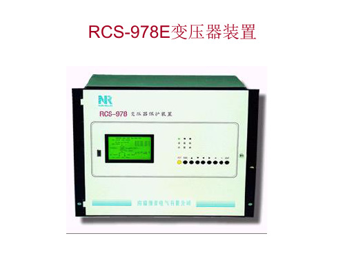
rcs-978运行说明_演示文稿
退出
220kV变压器主保护定值单 I侧后备保护定值单 II侧后备保护定值单 III侧后备保护定值单 IV侧后备保护定值单
液晶对比度 退出
差动电流 I侧电流电压 II侧电流电压 III侧电流电压 IV侧电流电压 零差电流 公共绕组电流 退出
III、IV侧和电流保护定值单
公共绕组后备保护定值单
参见培训资料第六章
1.52A
装置编号
TRA001
0.93A
57.7V
U/F: 1.000
各侧电 流,电压采 样平均值
0.29A 57.7V
00.29A 57.7V
F: 50.00Hz
过激磁测量倍数 频率
动作时保护液晶显示说明
报告序号 保护起动时间
No.008
保护动作报告
2000-01-19 10:28:03:0273 0023 工频变化量差动动作 A
间隙零序过流 零序过压
◎过负荷 ◎启动冷却器 ◎闭锁有载调压 过流
一 一
二 二 一 五
2 2
1 1 1 1
I-V 可经复合电压闭锁,I-III 可经方向闭 锁
零序过压
◎过负荷 ◎零序过压 过流 ◎过负荷 过流
一
一 一 一 一 一 一 一 一 一
1
1 1 2 1 1 1 1 1 1
可经复合电压闭锁
零序过流
压板 其他 退出
交流量采样 开入量状态 计算差电流 相角 退出
同保护板交流量采样 同保护板开入量状态
各侧电流相位夹角 各侧电压相位夹角 各侧电压与电流相位夹角 各侧调整后电流相位夹角 各侧零序电流相位夹角
定值 正常波形 故障波形 异常事件报 开入变位报告 退出
装置参数定值 系统参数定值 变压器保护定值 退出 同故障波形
北京落木源 IGBT驱动电源TX-PD107手册说明书

BEIJI NG L MY ELECTRO NIC S CO.,LTD TX-PD107大功率IGBT驱动电源TX-PD107产品手册BEIJI NG L MY ELECTRO NIC S CO.,LTD TX-PD107目录一.概述 (3)二、电气参数 (3)2.1 极限参数 (3)2.2 电性能参数 (3)2.3 工作条件 (3)三、尺寸结构 (4)3.1 外形尺寸 (4)3.2 引脚说明 (4)四、典型应用图 (5)五、相关产品信息 (5)5.1 TX- KA105特大功率IGBT驱动器 (5)5.2 TX- PD106高隔离电压DC-DC模块电源 (5)5.3 TX-PD220高隔离电压DC-DC模块电源 (5)5.4 TX-PA202 AC/DC IGBT驱动电源 (5)六、常见问题 (6)七、其它说明 (6)BEIJI NG L MY ELECTRO NIC S CO.,LTDTX-PD107TX-PD107 大功率 DC/DC 驱动电源一.概述• 专为特大功率输出的IGBT 驱动器KA105、KB304设计,最大输出功率15W 。
• 输入输出耦合电容小。
•输入电源极性保护。
二、电气参数 2.1 极限参数2.2 电性能参数除另有指定外,均为在以下条件时测得:Ta=25℃,Vi=15Vdc,负载均RL=60Ω2.3 工作条件BEIJI NG L MY ELECTRO NIC S CO.,LTDTX-PD107三、尺寸结构 3.1 外形尺寸3.2 引脚说明BEIJI NG L MY ELECTRO NIC S CO.,LTDTX-PD107四、典型应用图1. C1应靠近PD107管脚。
2. 如果驱动不需要正负电源,或驱动芯片内部已有分压电路,虚线框内可以取消。
3. 不允许输出短路。
4. 用户需注意,输入电源极性接反将被内部的二极管短路,短时间不会造成本电源损坏。
5. 电源输出可以空载,但空载电压稍微高些。
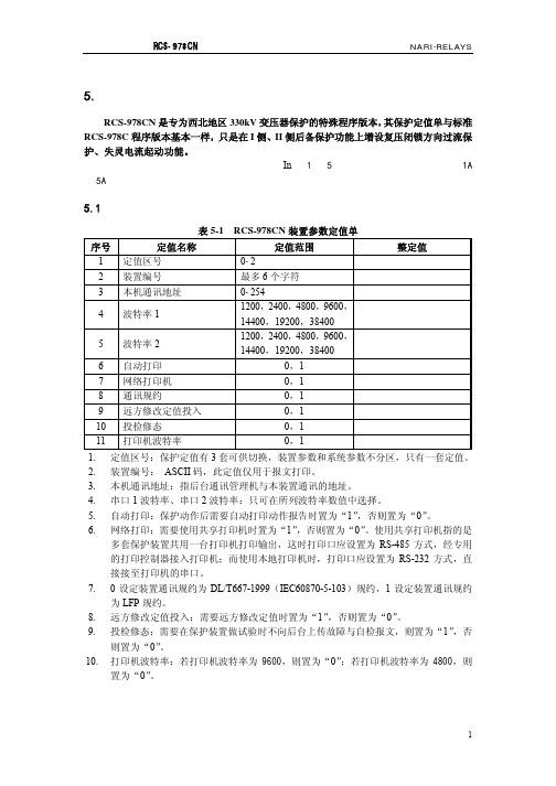
RCS978CN定值说明
序号
定值名称
定值范围
1 定时限过激磁 I 段 2 定时限过激磁 I 段时限 3 定时限过激磁 II 段
1.0—1.5 0—6000S 1.0—1.5
整定步长 0.001 0.1S 0.001
4
定值及说明——RCS-978CN
NARI-RELAYS
4 定时限过激磁 II 段时限
0—6000S
0.1S
0-10A 0-10A
0.01A 0.01A
7 低压绕组过流 TA10 副边 8 I 侧零序 TA7 原边 9 II 侧零序 TA8 原边 10 公共绕组零序 TA9 原边
0-10A 0-65535A 0-65535A 0-65535A
0.01A 1A 1A 1A
11 低压绕组过流 TA10 原边 12 TV 二次额定电压
5.1 装置参数定值单
表 5-1 RCS-978CN 装置参数定值单
序号
定值名称
定值范围
整定值
1 定值区号
0-2
2 装置编号
最多 6 个字符
3 本机通讯地址
0-254
4 波特率 1
1200,2400,4800,9600, 14400,19200,38400
5 波特率 2
1200,2400,4800,9600, 14400,19200,38400
6 自动打印
0,1
7 网络打印机
0,1
8 通讯规约
0,1
9 远方修改定值投入
0,1
10 投检修态
0,1
11 打印机波特率
0,1
1. 定值区号:保护定值有 3 套可供切换,装置参数和系统参数不分区,只有一套定值。
2. 装置编号: ASCII 码,此定值仅用于报文打印。
Stryker Power-PRO IT 6516 零件手册说明书

SOUTH AFRICA Stryker Osteonis PTY. LTD. 3 Susan Street Strydom Park Johannesburg, 2194 - South Africa Mailing Address:
PORTUGAL Stryker Portugal Produtos Medicos, LTDA. Avenida Marechal Gomes da Costa, 35 1800-255 Lisboa Portugal Phone: 011-35-1-21-839-49-10 Fax: 011-35-1-21-839-49-19
P.O. Box 48039 2129 Roosevelt Park Johannesburg, South Africa Phone: 011-27-11-791-4644 Fax: 011-27-11-791-4696
SPAIN Stryker Iberia SL c/Sepulveda n17 28108 Alcobendas Madrid Spain Phone: 011-34-91-728-35-00 Phone: 011-34-91-358-20-44 Fax: 011-34-91-358-07-48
NEDERLANDS Stryker Nederlands BV (P.O. Box 13, 4180 BA Waardenburg) 4181 CD Waardenburg The Nederlands Phone: 011-31-418-569-700 Fax: 011-31-418-569-777
RCS-978系列500KV变压器保护说明书
业务联系 技术支持 工程服务 质量保证
电话:(025)3406078 3439746 传真:(025)3438965
电话:(025)3429900-2091/2093 传真:(025)3429900-2091
电话:(025)2107703 传真:(025)2100770
电话:(025)2100660
5.定值内容及整定说明.................................................................................................................. 29
5.1 装置参数定值单................................................................................................................29 5.2 RCS-978A 定值单 .............................................................................................................29 5.3 RCS-978B 定值单 .............................................................................................................38 5.4 RCS-978C 定值单 .............................................................................................................43
RCS-978的变压器保护说明及特点
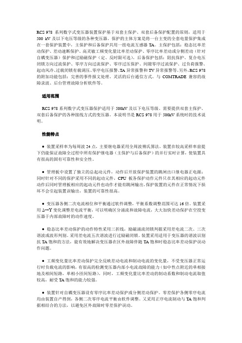
RCS-978系列数字式变压器装置保护基于双套主保护、双套后备保护配置的原则,适用于500 kV及以下电压等级的各种变压器。
保护的主体方案是将一台主变的全套电量保护集成在一套保护装置中,主保护和后备保护共用一组电流互感器TA。
主保护包括:稳态比率差动保护、差动速断保护、高灵敏工频变化量比率差动保护、零序比率差动或分侧差动(针对自耦变压器)保护和过励磁保护(定、反时限可选)。
后备保护包括:阻抗保护、复合电压闭锁方向过流保护、零序方向过流保护、零序过压保护、间隙零序过流保护、过负荷报警、起动风冷、过载闭锁有载调压、零序电压报警、TA异常报警和TV异常报警等。
另外,RCS-978的附加功能包括:完善的事件报文处理、灵活的后台通信方式、与COMTRADE兼容的故障录波、后台管理故障分析软件等。
适用范围RCS-978系列数字式变压器保护适用于500kV及以下电压等级、需要提供双套主保护、双套后备保护的各种接线方式的变压器。
本说明书是RCS-978用于500kV系统时的技术说明。
性能特点● 装置采样率为每周波24点,主要继电器采用全周波傅氏算法。
装置在较高采样率前提下仍能保证故障全过程中所有保护继电器(主保护与后备保护)的并行实时计算,使装置具有很高的固有可靠性和安全性。
● 管理板中设置了独立的总起动元件,动作后开放保护装置的跳闸出口继电器正电源;同时针对不同的保护采用不同的起动元件,CPU板各保护动作元件只在其相应的起动元件动作后同时管理板相应的起动元件也动作才能有跳闸输出。
保护装置的元件在正常情况下损坏不会引起装置误输出,装置的可靠性很高。
● 变压器各侧二次电流相位和平衡通过软件调整,平衡系数调整范围可达16倍。
装置采用Δ→Y变化调整差电流平衡,可以明确区分涌流和故障电流,大大加快差动保护在空投变压器于内部故障时的动作速度。
● 稳态比率差动保护的动作特性采用三折线,励磁涌流闭锁判据采用差电流二次、三次谐波或波形判别。
RCS-978

i1
φ
e=
e2 = − N 2
dφ dt
e
e2 i2) (
1234
可由磁通φ画出e 可由磁通φ画出e2波形。 3)由于电流互感器二次 侧相当于一个纯电阻回路, 侧相当于一个纯电阻回路, 由:e2=R2i2 可得二次电流i 波形。 可得二次电流i2波形。
TA
t
TA饱和时波形 饱和时波形
100 A 相(A) 0
变压器辅助保护
非全相保护 起动断路器失灵保护
2、典型配置方案
典型方案
两柜制 柜1:第一套主后备保护+高压侧操作箱+PRT
柜2:第二套主后备保护+中、低压侧操作箱+非电量及 辅助保护 三柜制 柜1:第一套主后备保护+PRT 柜2:第二套主后备保护+PRT(可选) 柜3:高压侧操作箱+中、低压侧操作箱+非电量及辅助 保护 500kV主变配置中操作箱由主接线决定其位置
非电量保护: 非电量保护:
通常变压器内部故障直接反映于变压器内部瓦 斯、压力、温度等非电量特征的变化,特别是轻微 故障(如少许的匝间故障)时往往这些非电量特征 的变化比常规的稳态比率差动保护更加灵敏。非电 量保护主要是重动主变本体来的信号 。 非电量保护动作通常跳主变各侧,在有备投的 情况下有可能需考虑闭锁备投。
220KV
I1
110KV
I d = I1 + I 2 + I 3 = 0
差动保护不会误动。 差动保护不会误动。 但是由于低压侧 饱和, 由于低压侧TA饱和 但是由于低压侧 饱和,测到 的电流I3很小,假设为0,则保护计 的电流 很小,假设为 , 算的差动和制动电流为: 算的差动和制动电流为:
日本罗宾汉RUBICON型号汇总--华南区总代理
NO.160 NO.170 NO.180 NO.232 NO.1900 NO.18
NO.261 NO.262 NO.263 NO.650
NO.670 NO.5400 NO.5500 NO.950B NO.970B
NO.RES-910 NO.920 NO.RES-102 NO.103 NO.104 NO.105 NO.RSD-903
套装扳手系列
NO.RCW-307 NO.RCW-309 NO.RCW-311 NO.RCW-314
NO.RCW-317 NO.RCW-320
气动系列
NO.RDG-220 NO.RDG-250A NO.RD-100R NO.RD-130RJ
NO.RR-127 NO.RR-127J NO.RR-950T NO.RAH-220QC
NO.REA-S05~S35 NO.REA-P0000~P1 NO.REA-T3~T10 NO.REA-H07~H32
NO.REA-N18~N25 NO.RU-900 NO.901
六边星批系列
NO.181 NO.191
NO.161 NO.161-4
NO.161-6
钳子系列
NO.RS-150 NO.RS-170 NO.RS-200 NO.RML150 NO.RD-125
NO.RCA-150 NO.RCA-200 NO.RCA-250 NO.RJP-528 NO.RWC-100
NO.RGL-006 NO.RGL-010 NO.RGL-012 NO.RMC-008
NO.207 NO.204-W NO.205-W
彩条两用批系列
NO.50 NO.88 NO.624 NO.627 NO.637
PCS-978变压器保护

零序[方向]过
流
间隙零序过 流
*2 TA5
TA9
1
* (低压侧)
35 kV
TA8
零序过 流
零序过 压
2
2
TA2
1
1
复合电压过流
[复合电压]过 流
TV2-1
TV2-2
[复合电压]过流
[复合电压]过流
I 母 II母
*2
TA3 1
*
TV3
I 母
(低压侧1支路)
*2
TA4 1
*
TV4
II母
另外还包括以下异常告警功能: 过激磁报警 过负荷报警 起动冷却器 过载闭锁有载调压 差流异常报警 差动回路TA断线 TA异常报警和TV异常报警 图中表示的是此型保护所能够适应的最大的接线方式,但其接线
方式并不一定符合实际应用。
PCS-978GE 典型应用配置(三圈变)
PCS-978系列变压器保护在现场已经成功应用近十年时间,积累 了丰富的实际应用经验,我公司在此基础上,结合最新的计算机技 术和用户日益复杂的应用需求,研发出了全新一代的PCS-978变压 器保护,它继承了PCS-978系列变压器保护的所有优点,并在保护 原理方面有了进一步的创新和改进,同时人机接口方面更加友好, 全面支持新一代的数字化变电站的应用要求。
NR1151 DSP插件分别完成保护计算和保护起动的功能以及测控的 测量与控制功能。
NR1152型DSP插件支持60044-8的FT数据接收功能。 NR1137型DSP插件支持GOOSE与SMV采样功能。
四. PCS978差动保护
4.1 差动保护基本原理
PCS-978GE调试手册

第一章回路检查1.1试验准备1.1.1试验仪器(1)经检验合格的继电保护测试仪、万用表、螺丝刀等常用工具(2)屏柜白图、技术说明书、调试大纲(3)设计蓝图1.1.2试验注意事项(1)实验前检查装置有无明显的损伤或螺丝松动。
(2)试验中不可带电插拔装置插件。
(3)注意直流回路不得短路;试验仪交流电压回路不得短路,交流电流不得开路。
(4)调试大纲与说明书不符的之处,以说明书为准。
(5)试验过程中防止人身触电伤害,避免带电接线、拆线1.2装置开入检查1.2.1注意事项#12板卡为开入板,当配置为NR1502D时为弱电光耦,配置为NR1502A时为强电光耦。
有压板、把手、复归按钮的开入量通过实际操作检查,其他开入量可通过短接的方式检查。
!检查过程中要注意防止直流短路。
1.2.2开入检查依次投入硬压板或点光耦开入方式完成试验,光耦导通开入为1,断开后开入为0。
操作菜单进入“主菜单”→“状态量”→“输入量”中查看。
1.3模拟量检查退出功能和出口硬压板,通过试验仪输入各侧电流电压模拟量,操作菜单进入“主菜单”→“模拟量”→“保护测量”和“启动测量”中查看装置交流采样。
(1)零漂检查不加入任何模拟量,查看装置电流电压的零漂值(2)采样精度检查为防止查看模拟量过程中保护长期动作,应退出所有保护功能。
在各侧各相电压电流中加入额定电压、电流,查看装置采样;在各侧各相加入不平衡的电压、电流,查看装置采样;1.4开关量输出检查(1)跳闸矩阵整定装置各元件的跳闸矩阵如下:假设差动保护整定为跳三侧(低压侧两分支),则对应位置为1,其它位为0,则二进制为0000 0000 0101 0101,转换为16进制为0055。
(2)跳闸出口检查 为方便检查全部跳闸出口,将差动保护的跳闸矩阵整定为FFFF ,即跳所有出口。
模拟故障使差动保护动作,使用万用表通断档依次检查出口是否闭合,出口经压板控制时,应验证压板能够起到断开动作回路的作用。
R-19组合式PET塑钢带捆扎机适合哪些环境用户
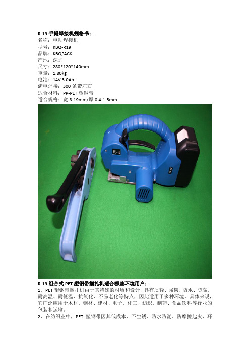
R-19手提焊接机规格书:
名称:电动焊接机
型号:KBQ-R19
品牌:KBQPACK
产地:深圳
尺寸:280*120*140mm
重量:1.80kg
电池:14V 3.0Ah
满电焊接:300条带左右
适合材料:PP-PET塑钢带
适合规格:宽8-19mm/厚0.4-1.5mm
R-19组合式PET塑钢带捆扎机适合哪些环境用户:
1、PET塑钢带捆扎机由于其特殊的材质和设计,具有质轻、强韧、防水、防腐、耐高温、耐低温、抗氧化、不易老化等特点,因此适用于多种环境。
具体来说,它广泛应用于木材、钢材、建材、电子、化工、纺织、制药、食品饮料等行业的包装和运输。
2、在纺织业中,PET塑钢带因其低成本、不生锈、防水防潮、防摩擦起火、环
保美观、易用耐用、高强度和高拉力等优势,成为替代钢带、钢丝及PP打包带的新型捆扎包装材料。
特别是对于棉花等原材料的包装,PET塑钢带能有效避免在运输过程中因摩擦产生火花而引发的安全风险。
3、此外,手动式打包机和铁扣捆扎机等配套工具的使用,使得PET塑钢带的打包过程更加快速、高效和可靠。
这些工具适用于各种规模的包装需求,从小型包装到大型货物的固定和封口,都能提供强力的紧固效果和稳定的性能。
- 1、下载文档前请自行甄别文档内容的完整性,平台不提供额外的编辑、内容补充、找答案等附加服务。
- 2、"仅部分预览"的文档,不可在线预览部分如存在完整性等问题,可反馈申请退款(可完整预览的文档不适用该条件!)。
- 3、如文档侵犯您的权益,请联系客服反馈,我们会尽快为您处理(人工客服工作时间:9:00-18:30)。
**********************************************************************************************************************************************************************OPTOWAY TECHNOLOGY INC. No .38, Kuang Fu S. Road, Hu Kou, Hsin Chu Industrial Park, Hsin Chu, Taiwan 303Tel: 886-3-5979798 Fax: 886-3-5979737BTRS-9780-1590G / BTRS-9780-1590-SPG1590 nm TX / 1510 nm RX , 3.3V / 2.5 Gbps RoHS Compliant Single-Fiber WDM Transceiver*********************************************************************************************************************************************************************FEATURESl Single Fiber WDM Transceiver l Speed up to 2.67 Gbpsl 1590 nm DFB LD Transmitterl High Sensitivity 1510 nm APD Receiver l Distance Up to 40 kml Single +3.3 V Power Supply l RoHS Compliantl PECL Differential Inputs and Outputs l LVTTL Signal Detect Outputl Wave Solderable and Aqueous Washablel Class 1 Laser International Safety Standard IEC 60825 CompliantAPPLICATIONSl WDM OC-48 / STM-16 Linksl SONET/SDH Equipment Interconnect l Fiber Channel LinksDESCRIPTIONThe BTRS-9780-1590G series is high performance module for single fiber communications by using 1590 nm transmitter and 1510 nm receiver. The transmitter section uses a multiple quantum well 1590 nm DFB laser and is a class 1 laser compliant according to International Safety Standard IEC 60825. The receiver section uses an integrated 1510 nm detector preamplifier (IDP) mounted in an optical header and a limiting post-amplifier IC. A PECL logic interface simplifies interface to external circuitry. LV-TTL Signal Detect is used.LASER SAFETYThis single mode transceiver is a Class 1 laser product. It complies with IEC 60825 and FDA 21 CFR 1040.10 and 1040.11. The transceiver must be operated within the specified temperature and voltage limits. The optical ports of the module shall be terminated with an optical connector or with a dust plug.ORDER INFORMATIONP/No.Speed (Gb/s)Distance (km)TX (nm)RX (nm)Voltage (V)PackageTemp (o C)TX Power (dBm) RX Sens. (dBm)BTRS-9780-1590G 2.5 / 1.25 80 1590 DFB 1510 3.3 2X5 SC 0 to 70 3 to -2 -28Absolute Maximum RatingsParameterSymbol Min Max Units NotesStorage Temperature Tstg -40 85 o COperating Temperature Topr 0 70 o C Air flow 1m/secSoldering Temperature --- 260 o C 10 seconds on leads only Power Supply Voltage Vcc 0 3.6 V Input Voltage --- GND Vcc V Output CurrentIout30mARecommended Operating ConditionsParameterSymbol Min Typ Max Units / NotesPower Supply Voltage Vcc 3.13 3.3 3.47 V Power supply Current Icc,TX +Icc,RX220 280 mAOperating Temperature Topr 0 70 oC / air flow 1m/secData Rate0.6222.4882.67Gb/sTransmitter Specifications (0o C < Topr < 70o C, 3.13V < Vcc < 3. 47V)Parameter Symbol Min Typ Max Units NotesOpticalOptical Transmit Power Po -2 3 dBm 1Output Center Wavelength λ1580 1620 nmOutput Spectrum Width σλ 1 nm RMS (σ)Side Mode Suppression Ratio SMSR 30 dBExtinction Ratio E R8.2 dBOutput Eye Compliant with IEEE 802.3zOptical Rise Time t r150 ps 20% to 80% Values Optical Fall Time t f150 ps 20% to 80% Values Relative Intensity Noise RIN -120 dB/HzTotal Jitter TJ 0.227 ns 2ElectricalData Input Current – Low I IL-350 µAData Input Current – High I IH350 µADifferential Input Voltage V IH - V IL300 1600 mVData Input Voltage – Low V IL - V CC-2.0 -1.58 V 3Data Input Voltage -- High V IH - V CC-1.1 -0.74 V 3Disable Input Voltage -- Low V TDIS,L0 0.8 V TX Output Enabled Disable Input Voltage -- High V TDIS,H Vcc – 1.3 Vcc V TX Ouput DisabledShut Off Time for TxDis t DIS 1 msNotes: 1. Output power is power coupled into a 9/125 µm single mode fiber.2. Measured with a 27-1 PRBS.3. These inputs are compatible with 10K, 10KH and 100K ECL and LVPECL inputs.Receiver Specifications(0o C < Topr < 70o C, 3.13 V < Vcc < 3. 47V)Parameter Symbol Min Typ Max Units NotesOpticalSensitivity--- --- --- -28 dBm 1Maximum Input Power Pin -9 --- --- dBmSignal Detect -- Asserted Pa --- --- -28 dBm Transition: low to high Signal Detect -- Deasserted Pd -45 --- --- dBm Transition: high to low Signal detect -- Hysteresis 1.0 --- dBWavelength of Operation 1480 1520 nm 2Optical Return Loss ORL 20 dBElectricalData Output Voltage Swing V OH– V OL0.575 0.930 VSD Output Voltage -- Low V OL0 0.8 VSD Output Voltage -- High V OH 2.0 Vcc+0.3 VSignal Detect Assert Time AS MAX100 µs OFF to ONSignal Detect Deassert Time ANS MAX300 µs ON to OFF Notes: 1. Minimum sensitivity and saturation levels at BER 1E-10 for a 223-1 PRBS.2. At least 30 dB optical isolation for the wavelength 1580 to 1620 nm.********************************************************************************************************************************************************************** OPTOWAY TECHNOLOGY INC. No.38, Kuang Fu S. Road, Hu Kou, Hsin Chu Industrial Park, Hsin Chu, Taiwan 303********************************************************************************************************************************************************************** OPTOWAY TECHNOLOGY INC. No.38, Kuang Fu S. Road, Hu Kou, Hsin Chu Industrial Park, Hsin Chu, Taiwan 303********************************************************************************************************************************************************************** OPTOWAY TECHNOLOGY INC. No.38, Kuang Fu S. Road, Hu Kou, Hsin Chu Industrial Park, Hsin Chu, Taiwan 303。
