DL-5335-1650-VSAS中文资料
单板

OptiX OSN 3500/2500/1500 智能光传输系统 设备手册
目录Biblioteka 5.6 STM-1 电接口单元 SEP/SEP1/EU08/EU04/OU08/TSB8/TSB4 ...................................... 5-31 5.6.1 功能 ....................................................................................................................... 5-32 5.6.2 原理 ....................................................................................................................... 5-33 5.6.3 面板说明 ................................................................................................................ 5-34 5.6.4 单板保护配置......................................................................................................... 5-35 5.6.5 单板参数配置......................................................................................................... 5-39 5.6.6 版本说明 ................................................................................................................ 5-40 5.6.7 技术参数 ................................................................................................................ 5-40
移动集团用户常用设备简介-代维学习资料

集团客户专线专网业务常用设备简介(第一版)编制:工维部Mlqing目录第1章瑞斯康达系列 (3)1.1 光纤收发器RC512(10/100M自适应以太光-电转换设备) (3)1.2 光纤收发器RC511(10/100M自适应以太光-电转换设备) (3)1.3 协议转换器RC952(10/100Base-T快速以太网电口至单路E1接口转换器) (4)1.4 协议转换器RC905(10/100Base-T快速以太网电口至单路E1接口转换器) (4)1.5 多路协议转换器RC953&RC954 (5)1.6 E1接口阻抗转换器RC909 (5)1.7 以太网复用器RCMA2201-60/30(2路E1和1路10/100M自适应以太网复用器) (6)1.8 V.35光端机RC831-30-FV35(2M-PDH光转V.35接口) (6)1.9 V.35至E1协议转换器 (7)第2章华为IAD系列 (7)2.1 IAD101H、102H、104H (7)2.2 IAD208H (8)2.3 IAD132E(T) (9)第3章烽火系列 (10)3.1 烽火PDH (10)3.2 烽火光纤收发器 (11)3.3 烽火协议转换器 (11)第4章PBX系列 (12)4.1 佳和PBX (12)4.2 希华HC4800 PBX (13)第5章华为交换机 (14)5.1 华为交换机S2000系列 (14)5.2 华为交换机S3500系列 (14)第6章EPON设备 (14)6.1 ONU:用户端使用设备 (14)6.2 OLT:局端机房设备 (15)第7章连接线类 (16)7.1 网线 (16)7.2 光连接器 (17)7.3 法兰盘 (17)7.4 跳纤 (18)7.5 2M头 (18)7.6 同轴电缆 (19)第8章综合布线中常用工具及材料 (19)第1章瑞斯康达系列1.1 光纤收发器RC512(10/100M自适应以太光-电转换设备)光纤收发器RC512主要用于企事业单位集团互联网或集团语音(IAD方式)接入。
中兴电源培训资料

中兴通讯电源产品技术经理培训教材本部事业部电源系统部二00二年四月目录第一章中兴电源产品部简介 (1)一、中兴通讯电源产品部发展概括 (1)二、中兴通信电源产品种类 (2)第二章通信电源基础知识 (6)第一讲通信电源发展概况 (6)一、通信电源的现状和发展趋势 (6)二、通信设备对电源系统的一般要求 (9)第二讲组合通信电源系统结构及功能 (10)第三章中兴通信电源产品特色 (15)第一讲中兴整流器技术 (15)一、工作基本原理 (15)二、中兴整流器技术特点 (16)第二讲中兴组合电源系统特点 (18)可靠的三级防雷网络 (19)自下而上全分布式的三级监控网络 (20)完善的蓄电池管理 (22)灵活多样的组网方式 (22)第三讲组网方式 (23)第四章中兴组合通信电源产品系列介绍 (27)第一讲ZXD5000 100A整流模块及其组成的电源系统 (27)一、ZXD5000 100A整流模块介绍 (27)二、ZXDU3000、ZXDU1500通讯电源系统简介 (29)第二讲ZXD2400 50A整流模块及其组成的电源系统 (32)一、ZXD2400 50A整流模块介绍 (33)二、ZXDU600E、ZXDU400通讯电源系统简介 (34)第三讲ZXD1500 30A整流模块及其组成的电源系统 (37)一、ZXD1500 30A整流模块介绍 (37)二、ZXDU300(2米高机柜)ZXDU300(1.6米高机柜) 通讯电源系统简介 (39)第四讲ZXD800E 15A整流模块及其组成的电源系统 (41)一、ZXD800E 15A整流模块介绍 (41)二、ZXDU150、ZXDU75、ZXDU45通讯电源系统简介 (43)第五讲+24V组合通信电源系统 (46)第五章中兴UPS产品介绍 (47)ZXUPS S501 (47)ZXUPS S502 (48)ZXUPS S503 (48)ZXUPS S506 (48)ZXUPS S510 (49)ZXUPS M510 (49)ZXUPS M515 (49)ZXUPS M520 (50)ZXUPS M530 (50)ZXUPS L005 (50)ZXUPS L006 (50)第六章通信电源计算配置方法 (52)第七章通信电源市场概述 (55)第一讲国内主要通信电源厂家及其产品特色 (55)一、华为公司 (55)公司背景 (55)产品系列 (56)产品技术特点 (56)我司对策 (57)二、武汉洲际通信电源集团有限公司 (57)公司背景 (57)产品特点 (57)我司对策 (58)三、中达-斯米克电器电子有限公司 (58)公司背景 (58)产品系列 (58)与我司技术优、劣势对比 (59)我司对策 (59)四、珠江电信设备制造有限公司 (59)公司背景 (59)产品系列 (59)产品技术特点 (60)五、新西兰SWITCHTEC公司 (60)公司简介 (60)产品介绍 (60)我司对策 (61)六、亚澳通信电源有限公司 (61)公司概况 (61)产品技术特点简介 (62)我司对策 (62)七、动力源责任有限公司 (63)公司背景 (63)产品介绍 (63)产品优、劣势分析 (64)我司对策 (64)八、通力环电气有限公司 (65)公司背景 (65)产品系列 (65)产品特点 (66)九、意达公司 (67)产品系列 (67)产品技术特点 (68)第二讲我司电源产品市场拓展策略 (68)一、市场分类 (68)二、不同市场拓展策略 (69)三、2002年我司电源产品市场拓展策略 (70)第八章推荐参考书籍清单 (75)第一章中兴电源产品部简介导读:这一章主要介绍了中兴电源产品部的发展概况和现有的产品系列,是本教材的入门篇,各产品系列是本章掌握重点,同时关于产品部的发展、近几年的销售业绩等情况也经常用于客户交流中。
瑞斯康达光端机

瑞斯康达光端机LEKIBM standardization office【IBM5AB- LEKIBMK08- LEKIBM2C】光端机光端机 (1)1.标准型PDH光端机 (2)1.1 E1光端机 (2)2.1 V.35光端机 (4)2.扩展型PDH光端机 (6)2.1 双扩展插槽光端机 (6)3.扩展子卡 (8)3.1 四路E1接口扩展子卡 (8)3.2 V.35接口扩展子卡 (8)3.3 以太网接口扩展子卡 (9)3.对通列表 (10)3.1 PDH光端机 (10)1.标准型PDH光端机1.1 E1光端机单路E1光端机双路E1光端机四路E1光端机四路E1光端机四路E1光端机八路E1光端机八路E1光端机八路E1光端机八路E1光端机产品简述:标准型PDH光端机系列产品是通过光纤来远距离传送单路或多路E1业务,它采用了业内领先的技术及专用的超大规模集成电路,并结合专用数字复接芯片开发而成的光传输产品。
该类设备支持点到点组网,易于安装维护,配合机箱可实现局端、远端统一网管,可以迅速实现故障定位,在加快故障响应速度的同时,节省了运维成本。
标准型PDH光端机是北京瑞斯康科技发展有限公司根据市场需求,以超大规模集成电路为核心,采用业界功能完善的数字集成芯片,通过强大的研发团队相互配合研制生产的光传输设备。
该设备通过光来延伸现有的传输网络,支持一路或多路E1传输,适应于传统的PDH网络、SDH网络、DDN网、专网等,是一款性价比很高的光传输产品。
光端机分为台式设备和集中式机框设备,都具备高度集中的网络管理功能。
解决方案:功能特性:➢E1接口符合ITU-T G.703标准,支持2048Kbps±50 PPM透明传输。
➢采用超大规模ASIC芯片,功耗低,四层电路板设计,可靠性高。
➢支持SNMP本地和远端网管,提供强大的网管功能。
➢提供完备的告警与指示,可显示本端、远端设备的告警信息。
➢具备对远端设备掉电检测功能,用于监测远端设备实际工作状态。
DL-5105-1650中文资料
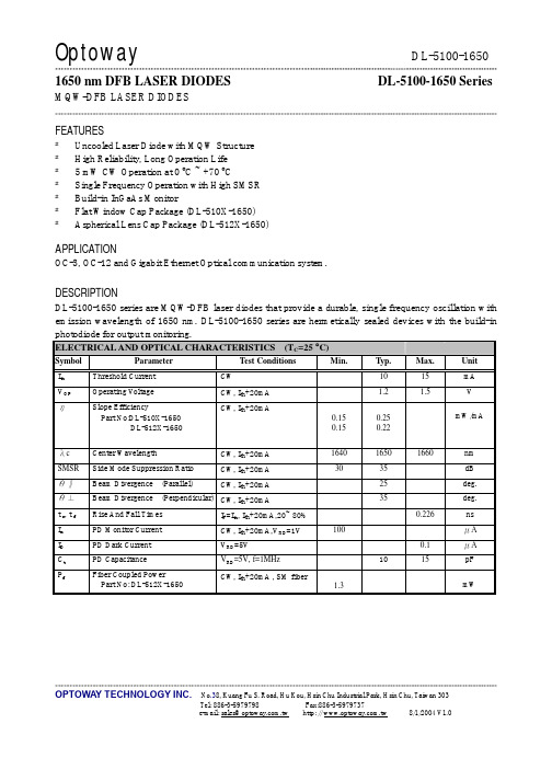
**************************************************************************************************************************************************************OPTOWA Y TECHNOLOGY INC. No .38, Kuang Fu S. Road, Hu Kou, Hsin Chu Industrial Park, Hsin Chu, Taiwan 303Tel: 886-3-5979798 Fax:886-3-59797371650 nm DFB LASER DIODES DL-5100-1650 SeriesMQW-DFB LASER DIODES**************************************************************************************************************************************************************FEATURES² Uncooled Laser Diode with MQW Structure ² High Reliability, Long Operation Life ² 5 mW CW Operation at 0 ºC ~ +70 ºC² Single Frequency Operation with High SMSR ² Build-in InGaAs Monitor² Flat Window Cap Package (DL-510X-1650) ² Aspherical Lens Cap Package (DL-512X-1650)APPLICATIONOC-3, OC-12 and Gigabit Ethernet Optical communication system.DESCRIPTIONDL-5100-1650 series are MQW-DFB laser diodes that provide a durable, single frequency oscillation with emission wavelength of 1650 nm. DL-5100-1650 series are hermetically sealed devices with the build-in photodiode for output monitoring.ELECTRICAL AND OPTICAL CHARACTERISTICS (T C =25 °C)Symbol ParameterTest ConditionsMin. Typ. Max. Unit I th Threshold Current CW10 15 mA V OPOperating V oltage CW, I th +20mA 1.2 1.5 V ηSlope EfficiencyPart No:DL-510X-1650 DL-512X-1650 CW, I th +20mA0.15 0.15 0.25 0.22mW/mAλc Center WavelengthCW, I th +20mA 1640 1650 1660 nm SMSR Side Mode Suppression Ratio CW, I th +20mA 30 35 dB θ‖ Beam Divergence (Parallel)CW, I th +20mA25 deg. θ⊥Beam Divergence (Perpendicular) CW, I th +20mA 35 deg. t r , t f Rise And Fall Times I F =I th , I th +20mA,20~ 80% 0.226 ns I m PD Monitor Current CW, I th +20mA,V RD =1V 100 μA I D PD Dark Current V RD =5V 0.1 μA C t PD CapacitanceV RD =5V, f=1MHz 10 15 pF P f Fiber Coupled PowerPart No: DL-512X-1650CW, I th +20mA , SM fiber1.3mW**************************************************************************************************************************************************************OPTOWA Y TECHNOLOGY INC. No .38, Kuang Fu S. Road, Hu Kou, Hsin Chu Industrial Park, Hsin Chu, Taiwan 303Tel: 886-3-5979798 Fax:886-3-5979737Note: Specifications subject to change without notice.ORDER INFORMATIONPart No.: D L − 5 1 □ □ □ − 1 6 5 0。
南通河海动力设备 DLM1650河海柴油发电机 说明书

河海柴油发电机组技术参数表机组型号DLM1650/1875 kV A主用功率 1500 kWkV A/2062.5备用功率 1650 kW标准配置z MITSUBISHI日本三菱发动机,型号:S16R-PTA2z MEGATON 麦格特交流发电机,型号:MWL 48OGz标准槽钢底座,集成高效减震装置z直流高能启动型铅酸蓄电池z输出断路器z手动控制屏z工业型消声器、波纹避震节z安装及操作指导手册z标准输出频率/电压:(额定功率因数 0.8滞后):50Hz: AC 230/400V (三相四线)标准机组尺寸及重量机组尺寸 (L×W×H)--(mm) 5311×2580×3000净重(kg,不含冷却液及机油)12060噪音值(dB(A),机组旁1m)<105dB发动机参数型号:S16R-PTA2 额定转速(RPM):1500气缸数:16 最大输出功率(kW):1760气缸排列方式:V 燃油规格、等级:中国0#(轻柴油)缸径/行程(mm):170.0/180 燃油消耗量(L/h):432气缸总容积(L):65.37 润滑油规格、等级:API-CD级以上压缩比:13.5:1 润滑油总容量(L):230进气方式:涡轮增压润滑油消耗量(L/h):3.46调速方式:电子调速润滑油正常工作温度(℃):110允许最大背压(kPa):5.9 排烟最高温度(℃):520冷却方式:闭式循环水冷燃气量(m3/min):143冷却水总容量(L) :445 排烟量(m3/min):379节温器调节温度(℃) :71-85排风量(m 3/min ):2040发电机设计标准满足GB755, BS EN60034, BS5000, VDE0530, NEMA MG1-32, IEC34等标准MEGATON 麦格特发电机参数励磁方式 自励磁 励磁控制方式 AVR 绝缘等级 H 防护等级 IP 22 温升等级 H 额定功率因数 0.8 绕组节距 2/3 电压调整率 ≤±1.0%电压调整范围≥±10%轴承数1标定环境z 环境温度 : ≤40℃ z 相对湿度 : ≤60%z海拔高度 : ≤1000m符合 ISO3046 及 ISO8528的要求。
DL-5335S-1650-XFAS中文资料
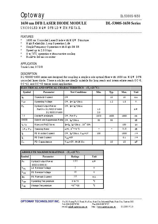
*******************************************************************************************************************************************************OPTOWA Y TECHNOLOGY INC. No .38, Kuang Fu S. Road, Hu Kou, Hsin Chu Industrial Park, Hsin Chu, Taiwan 3031650 nm DFB LASER DIODE MODULE DL-5300S-1650 SeriesUNCOOLED MQW DFB LD WITH PIGTAIL*******************************************************************************************************************************************************FEATURES² 1650 nm Uncooled Laser Diode with MQW Structure ² High Reliability, Long Operation Life² Single Frequency Operation with High SMSR ² Speed up to 2.5 Gbps² 0 to 70o C operation without active cooling ² Build-in InGaAs monitorAPPLICATIONTrunk Line, OTDRDESCRIPTIONDL-5300S-1650 series are designed for coupling a single mode optical fiber with 1650 nm MQW DFB uncooled laser diode. These modules are ideally suitable for long reach and intermediate reach OC-3, OC-12, and OC-48 transmission application.ELECTRICAL AND OPTICAL CHARACTERISTICS (T C =25 °C)Symbol ParameterTest ConditionsMin. Typ. Max. Unit I th Threshold Current CW10 15 mA V OP Operating V oltageCW, I F = I th +25mA1.2 1.5 V P fOptical Output Power Part No: DL-532XS-1650 DL-533XS-1650 CW, I F = I th +25mA 1.0 2.0mW λc Center Wavelength CW, Po= P f 1640 1650 1660 nm SMSR Side Mode Suppression Ratio CW, I th +25mA 30 35 dB t r , t f Rise And Fall Times I F =I th , I th +25mA , 20~ 80% 150 ps ΔP f / P f Tracking Error APC, 0~+70 ºC - - ±1.5 dB I m PD Monitor Current CW, I th +25mA ,V RD =1V 100 1500 μA I DPD Dark CurrentV RD =5V0.1μAC tPD CapacitanceV RD =5V , f=1MHz10 15 pFABSOLUTE MAXIMUM RATINGS (T C =25 ºC)Symbol ParameterRatings Unit P o Optical Output Power (532XS/533XS) 1.5/3 mW V RL LD Reverse V oltage 2 V V RD PD Reverse V oltage 10 V I FD PD Forward Current 1.0 mA T opr Operating Temperature 0 to 70 ºC T stgStorage Temperature-40~+85ºC*******************************************************************************************************************************************************OPTOWA Y TECHNOLOGY INC. No .38, Kuang Fu S. Road, Hu Kou, Hsin Chu Industrial Park, Hsin Chu, Taiwan 303ORDER INFORMATIONPart No.: D L − 5 3 □ □ □ − 1 6 5 0 − □ □ □ □。
MBRS1650中文资料

- 118 -
元器件交易网
RATINGS AND CHARACTERISTIC CURVES (MBRS1635 THRU MBRS1660)
FIG.1- FORWARD CURRENT DERATING CURVE
20 150
FIG.2- MAXIMUM NON-REPETITIVE FORWARD SURGE CURRENT
- 119 -
D2PAK
Hale Waihona Puke Mechanical Data
Cases: JEDEC D2PAK molded plastic body Terminals: Lead solderable per MIL-STD-750, Method 2026 Polarity: As marked Mounting position: Any Mounting torque: 5 in. - lbs. max Weight: 0.08 ounce, 2.24 grams
MCP1650
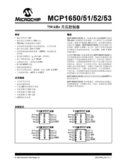
90.9 kΩ
COUT 10 µF 陶瓷电容
10 kΩ
DS21876A_CN 第 4 页
2004 Microchip Technology Inc.
MCP1650/51/52/53
1.0 电气特性
最大额定值 †
VIN 对 GND ........................................................... 6.0V CS,FB,LB,LBO,SHDN,PG,EXT............ GND – 0.3V 至
Q
EXT
DS21876A_CN 第 2 页
2004 Microchip Technology Inc.
MCP1650/51/52/53
MCP1651/2/3 结构框图
MCP1650/51/52/53
0&3᮴⡍ᗻ 0&3⬉∴Ԣ⬉य़Ẕ⌟ 0&3⬉⑤ℷᐌ⢊ᗕẔ⌟˄3*˅ 0&3⬉∴Ԣ⬉य़Ẕ⌟3*
中列出的数据可能超出确定的工作范围 (如:超出了正常的工作电压范围),因此不在担保范围。
注:除另有说明外, VIN = 3.3V, VOUT = 12V, CIN = 10 µF (X5R 或 X7R 陶瓷电容), COUT = 10 µF (X5R 或 X7R 电容), IOUT = 10 mA, L = 3.3 µH, SHDN > VIH, TA = +25°C。
参数
符号 最小值 典型值 最大值 单位
条件
关断时输入
逻辑高电平输入
VIN-HIGH
逻辑低电平输入ຫໍສະໝຸດ VIN-Low输入泄漏电流
ISHDN
电池低电压检测 (仅 MCP1652/MCP1653)
ALCATEL传输设备简明维护手册

2X140M/155M 电支路盘前面板图
--A绿灯—机盘投入使用指示 红灯---机盘内部故障指示
时钟盘前面板图
--Alcatel--
13/76
1 红灯—机盘内部故障指示 注意:一个子架上至少需要一块时钟盘,设备才能正常工作。
公务盘前面板图
--Alcatel--
14/76
中国联通全国干线网
ALCATEL设备日常维护建议
阿尔卡特传输设备简明维护手册 (Alcatel)
阿尔卡特传输系统部
目录
阿尔卡特设备简介…………………………………………………………………………………5 1664SM……………………………………………………………………………………5 设备简介………………………………………………………………………….5 设备面板图……………………………………………………………………….5 机盘示意图……………………………………………………………………….9 设备部分指标……………………………………………………………………21 1666SR…………………………………………………………………………………...26 设备简介………………………………………………………………………….26 设备面板图……………………………………………………………………….27 机盘示意图……………………………………………………………………….30 设备部分指标…………………………………………………………………….37 1650SMC………………………………………………………………………………….41 设备简介………………………………………………………………………….41 设备面板图……………………………………………………………………….44 机盘示意图……………………………………………………………………….45 日常维护注意事项………………………………………………………………………………….55 一些基本维护操作………………………………………………………………………………….56 机盘的插拔…………………………………………………………………………………56 公务话机的使用……………………………………………………………………………57 机盘的复位…………………………………………………………………………………57 硬件告警信号的处理………………………………………………………………………58 故障处理的基本方法………………………………………………………………………59 故障处理流程………………………………………………………………………………60 售后服务联系………………………………………………………………………………61
DLSeries 辅助设备简介说明书

2For use with the Power Supply Analysis option■See the bulletin 7019-30E for detailed specifications.■When using the DL to power the current probes, make sure that the total current consumption of the probes does not exceed the DL’s probe power rating. See the following web site for details./tm/probe/Number of power supply connectors: 40.5 VRated output current: +12 V: 2.5 A, -12 V: 2.5 ABandwidth: DC to 100 MHz(-3dB)Maximum continuous input range: 30 ArmsAmplitude accuracyBandwidth: DC to 10 MHz(-3dB)Bandwidth: DC to 50 MHz(-3dB)Maximum continuous current input range: 30 ArmsAmplitude accuracy(0 to 30 Arms): ±1.0% of rdg ±1 mV3* Cable only works with newer 700924, 700925 and 701921 probes that indicate "6 VDC or 9 VDC"at the probe input power connector.Differential Probe Selection GuideThe B9852MJ cable supplies power to the 700924,700925 and 701921 differential probes* from the DL probe power connectors. (The probe power option is Used to connect an oscilloscope having a 1 M to a probe with a 50 Ω output. It is required when using the 701920 and 701922 probes with the DL1600 se-Bandwidth: DC to 100 MHz(-3dB)Input attenuation ratio:Switch between 1/100 and 1/1000Bandwidth: DC to 100 MHz(-3dB)Input attenuation ratio: Switch between 1/10 and 1/100Maximum allowed differential voltageBandwidth: DC to 15 MHz(-3dB)Input attenuation ratio: Switch between 1/10, 1/100Maximum allowed differential voltage 500 V(DC+ACpeak) or 350 Vrms (1/100)Bandwidth: DC to 200 MHz(-3dB)Input attenuation ratio: 1/10(fixed)Maximum allowed differential voltage: ±20 V(DC+ACpeak)Bandwidth: DC to 500 MHz(-3dB)Input attenuation ratio: 1/10(fixed)Input impedance: 100 K Ω /2.5 pF4For DL1700E, 7400 series 1.2 m long (701941), 3.0 m long (701942)Bandwidth: 500 MHz (701941), 350 MHz (701942)Connecfor type: SMABandwidth: 1.0 GHz (701912)1.5 GHz (701914)For the DL1600 series For the DL1700E, 7400 series For the DL750/P and SL1400 isolation modulesisolated input modules)5*1: The B9852HF contains the following eleven(11) kinds of accessories.(Insulation cap, IC cap, BNC adapter, Rigid tip, Spring tip (Ø: 0.80 mm), Spring tip (Ø: 0.38 mm), Ground spring, Adjustment tool, Pincher tip, Standard ground lead, Color coding rings)*2: Input Capacitance: Capacitance at the tip of the probeCompensation Range: Compensation Range for the input capacitance of the oscilloscopeSee the following web site for details of these passive probes./tm/probe/For 701943 (PBA500) and 700939For 701943 (PB500) and 700939Standard accessories include: Adapter, red wire (3),black wire (3)For 701943 (PB500) and 700939Order Q’ty: 10 (1 set)A clip set designed for the 700988,11 accessories have been included in this set (See below *1).6■ See the following web site for details./tm/probe/Maximum toggle frequency: 100 MHzInput impedance (typical value): 1 M⍀/10 pFMaximum toggle frequency: 250 MHzInput impedance (typical value): 10 k⍀/9 pFNon-isolated inputTwo Measurement leads(B9879PX and B9879KX) Use with measurement lead 758917 and 758922,Attached to the tips of logic probe (701980 or 701981)or mini-clips ( B9852CR ), the IC clips can be used toclip contiguous 0.5-mm pitch terminals. A total of 10A set of 0.8 m long red and black test leads, used incombination with a pair of optional 758922 or 758929Rated at 300 V. Attaches to the 758917 test leads.7589297See the following web site for detailed dimensions./tm/img/Bu/701965/tm-701965_01.gif NDIS cable(5 m) included D-sub cable(5 m) included Supports Shunt-Cal A 1.5 m long connector-to-connector adapter cable complying with NDIS-MIL An NDIS connector for direct connec-For the DC power supply model (/DC).Cigarette lighter plug type Powers instrument for approx. 2 hours For connection between DL1640 Series and es standard with the 701680 battery box.For the DC power supply model (-DC).8Use with DL750/P and SL1400 isolation modulesFor High-voltage measurements1000 Vrms-CAT2,1.8 m longSafety BNC(male) to safety banana(female) use incombination with 701959, 701954, 758921, 7589221000 Vrms-CAT2(BNC-BNC), 1 mSet contains one black and one red clip.Set contains one black and one red clip.2A 1 m long (366924) and 2 m long(366925) BNC-BNC cables.A 1 m long BNC-alligator clip cable.Use only for circuits having voltageDo not use this cable for purposes otherthan DL750/1600/1700/7400A subassembly of 1.2 m long test leadswith alligator-clip adapters.9Three pockets are provided for storing accessories.Three pockets are provided for storing accessories and the user’s manual.Can store the DC power supply model and the BatterySoft type carrying case.Hard type carrying case.Three pockets are provided for storing accessories and the user’s manual.Banana-plug (male)-BNC e for circuits having voltage levels no T-adapter for BNC e for circuits having voltage levels no Safety-terminal-binding-post e for circuits having voltage levels no Used to connect an oscilloscope hav- A BNC (jack)-RCA (plug) adapter.An adapter for fitting a 4 mm widebanana plug to a BNC connector (male).10HandleKeyboard trayMouse standattachmentscrewMousestand, SL1400Paper width: 210 mm Cable holderPowerStrip (/B option)BraceCompact Instrument Cart500 mm (W) ϫ 560 mm (D) ϫ 705 mm (H)/A option: keyboard, mouse tableFor the DL1600, DL1700E, DL7400 seriesPaper width: 112 mmFor the DL750, DL9000 seriesPaper width: 112 mm11 1. 701992 XViewer/tm/701992/2. 700919 Waveform Viewer for DL series/tm/700919/a aModel Numbers and Suffix CodesVisit the following web sites for details about this software:3. Wirepuller/tm/wirepuller/4. MATLAB tool kit/tm/701991/Xviewer allows you to view andanalyze waveform data that has beenobtained and saved using either theDL series.Wirepuller displays an image of thefront panel DL Series on your PC formonitoring waveform signals.You control the DL Series by simplyThe MATLAB tool kit for DL series is aWaveform Viewer lets you viewwaveforms on your PC, just as youview them on the DL Seriesinstrument.Subject to change without notice.[Ed : 05/b] Copyright ©2004Printed in Japan, 707(KP)YOKOGAWA ELECTRIC CORPORATIONCommunication & Measurement Business Headquarters /Phone: (81)-422-52-6768, Fax: (81)-422-52-6624E-mail:********YOKOGAWA CORPORATION OF AMERICA Phone: (1)-770-253-7000, Fax: (1)-770-251-6427YOKOGAWA EUROPE B.V.Phone: (31)-33-4641858, Fax: (31)-33-4641859YOKOGAWA ENGINEERING ASIA PTE. LTD.Phone: (65)-62419933, Fax: (65)-62412606MS-16Ea a a a *Microsoft, Windows are trademarks or registered trademarks of Microsoft Corporation in the US and other countries.*MATLAB is a registered trademark of the Math Works, Inc in the US.。
神州数码D-Link系列产品

DES-6000 可网管机箱式千兆以太网交换机
技术指标 §支持的网线类型: - 10Base-T: 3,4或5类非屏蔽双绞线(UTP)(≤100m) EIA/TIA-568 100 欧 屏 蔽 双 绞 线 ( STP ) (≤100m) - 100Base-TX: 2对或4对5类非屏蔽双绞线(UTP)(≤100m) EIA/TIA-568 100 欧 屏 蔽 双 绞 线 ( STP ) (≤100m) - 100Base-FX: 62.5 μm多模光纤(≤2km)
DGS-3204、DGS-3208F和DGS-3208TG 可网管千兆以太网主干交换机
技术指标
§IEEE 802.1Q VLAN
DGS3204
2048组
§IEEE 802.1d生成树(Spanning Tree)
√
§IEEE 802.3x流量控制(全双工)
√
§Internet 工作组管理协议(IGMP)
•接入 层
•接入 层
•接入 层
网络设计是否成功,直接影响整个网络的正常运营 和经济效益
•用户 •用户 •用户 •用户
PPT文档演模板
神州数码D-Link系列产品
目录
核心层交换机
§DES-6000——可网管机箱式千兆以太网交换机 §DGS-3208F、DGS3208TG——可网管千兆以太网主干交换机 §DES-5220TF——可网管机箱式百兆以太网主干交换机
1000Base-SX:
•62.5μm多模光纤(≤275m) •50μm多模光纤(≤550m)
PPT文档演模板
神州数码D-Link系列产品
•核心层主干交换机
DGS-3204、DGS-3208F和DGS-3208TG 可网管千兆以太网主干交换机
1650 操作与维护手册说明书

LIFT CORP.11921 Slauson Avenue.Santa Fe Springs, CA. 90670(800) 227-4116MM-1650OPERATION &MAINTENANCEMANUALCMAXON Lift Corp. 2000M-00-34APRIL 2000LIFT CORP .11921 Slauson Ave.Santa Fe Springs, CA. 90670CUSTOMER SERVICE:(562) 464-0099(800) 227-4116FAX: (888) 771-7713TECHNICAL SERVICE:(800) 8-MAXTEK (862-9835)WARRANTY POLICY & PROCEDURENEW LIFTGATE WARRANTYTerm of Warranty: 2 Years from Date of In-ServiceType of Warranty: Full Parts and LaborMAXON agrees to replace any components which are found to be defective during the first2 years of service, and will reimburse for labor based on MAXON’s Liftgate Warranty Flat Rate Labor Schedule. (Call MAXON Customer Service for a copy).All claims for warranty must be received within 30 Days of the repair date, and include thefollowing information:1. Liftgate Model Number2. Liftgate Serial Number3. Description of Problem4. Corrective Action Taken, and Date of Repair.5. Parts used for Repair, Including MAXON Part Number(s).6. MAXON R.G.A. # and/or Authorization # if applicable (see below).7. Person contacted at MAXON if applicable.PURCHASE PART WARRANTYTerm of Warranty: 1 Year from Date of Purchase Type of Warranty: Part Replacement and Replacement Labor.MAXON will guarantee all returned genuine replacement parts upon receipt, and inspectionof parts and invoice. All Warranty repairs must be performed by an authorized MAXON warranty station.For major repairs, MAXON’s Warranty Department must be notified, and an “AuthorizationNumber” received. Major repairs would generally be considered repairs made to the structural assembly of the liftgate and/or repairs not outlined in the MAXON Liftgate Waranty Flat Rate Schedule.Major components (i.e. hydraulic pumps, cylinders, valves, or failed structural parts) mustbe returned, freight pre-paid, prior to the claim being processed. To ensure timely processing of these warranty claims, an R.G.A. (Returned Goods Authorization) number must be obtained from MAXON’s Warranty Department prior to the return of any defective part. Defective Parts must be returned within 60 days of the claim date for consideration to:Warranty Dapartment, MAXON Lift Corp.5920 Alameda St., Huntington Park, CA. 90255MAXON’s warranty policy does not include the reimbursement for travel time; towing;vehicle rental; service calls; fabrication of parts which are available from MAXON; oil; defects due to misuse or abuse; loss of income due to downtime.MAXON’s Flat Rate Labor Schedule times takes into consideration time required fordiagnosis of problem.Warranty and Technical Information is available by calling MAXON’s Customer ServiceDepartment.NOTE: Check with Customer Service Department for updated versions of Manuals on an annual basis.Table of ContentsWARNING...................................................................................................................PAGE 4 OPERATION SECTION...........................................................PAGE 5 DECALS AND DECAL PLACEMENT........................................................................PAGE 6 LIFTGATE TERMINOLOGY.........................................................................................PAGE 8 OPERATING INSTRUCTIONS.....................................................................................PAGE 9 POSITION OF LOAD.................................................................................................PAGE 10 MAINTENANCE SECTION....................................................PAGE 11 SPECIFICATIONS....................................................................................................PAGE 12 PERIODIC MAINTENANCE CHECKLIST.................................................................PAGE 13 PARTS BREAKDOWN DRAWINGS.....................................PAGE 14 PARTS DRAWINGS (PAGE 1)..................................................................................PAGE 15 PARTS DRAWINGS (PAGE 2)..................................................................................PAGE 16 PARTS DRAWINGS (PAGE 3)..................................................................................PAGE 18 HYD. COMPONENTS, GRAVITY DOWN...................................................................PAGE 20 ELECTRICAL COMPONENTS.................................................................................PAGE 21 ELECTRICAL AND HYDRAULIC SCHEMATIC.........................................................PAGE 2211921 Slauson Ave. Santa Fe Springs, CA. 90670 (800) 227-4116 FAX (888) 771-7713PAGE 41.Read the Maintenance Manual and understand it thoroughly before any maintenance of this unit is done.2.Read the YELLOW urgent warning decal on the side of the vehicle close to the unit before operating.3.If decals are dirty, clean them. If decals are defaced or missing, replace them. Free replace-ments are available from the manufacturer. See information at the end of the Warnings 4.Be aware that the safety and location of other people or objects should be considered before operation of this unit. Stand to one side of platform while operating this unit.5.Do not stand under, or have any foreign object under the Platform when lowering. Be sure that the lowering of the Platform and/or Flipover will miss your feet!6.Keep fingers, hands, arms, legs, and feet clear of moving parts when operating this unit.7.If during your maintenance procedure, it becomes necessary to ride the platform, keep your feet and any foreign objects clear of the rear edge of the platform. Otherwise your feet or the foreign objects could become trapped between the edge of the platform and the vehicle bed.8.Inspect all Roll Pins monthly, to insure that they are not broken. Replace if broken.9.Inspect all hydraulic hoses and fittings annually. Check for cracks and deterioration, and replace if necessary.10.Disconnect battery when replacing parts or servicing.11.Do not allow children to ride, play with, or operate this unit.12.In the event of an emergency while operating the unit, release the toggle switch and the unit will stop immediately.13.A properly installed Lift should operate smoothly and the only noise during the operation of this unit should be from the Pump Unit during the raising of the Platform. Any scraping,grating or audible indications of rough operation will need investigating. The cause will need resolving before any further deterioration of performance occurs.14.Use only Maxon Authorized Parts for replacement. Replacement parts should be ordered from:MAXON LIFT CORP . Parts Department11921 Slauson Ave., Santa Fe Springs, Ca. 90670Phone: (800) 227-4116WARNING11921 S l a u s o n A v e . S a n t a F e S p r i n g s , C A . 90670 (800) 227-4116 F A X (888) 771-7713PAGE 5OPERATION SECTION11921 Slauson Ave. Santa Fe Springs, CA. 90670 (800) 227-4116 FAX (888) 771-7713PAGE 6DECALS AND DECAL PLACEMENTThe Maxon liftgate must have all warning and caution decals attached in readable condition. If decals are defaced or missing, replace them. Freereplacements are available from Maxon. Contact:DecalDecal “C”“D”DecalDecal Maxon Lift Corp., Parts Department11921 Slauson Ave., Santa Fe Springs, Ca.90670Phone: (800) 227-4116FAX: (888) 771-7713Decal Decal “C”Decal11921S la u s o n Av e .S a n t a F e Sp r i n g s , C A . 9067(800) 227-4116 F A X (888) 771-7713PAGE 7DECALS AND DECAL PLACEMENTWARNINGSTAND CLEAR WHENRELEASING PLATFORM STORAGE LATCHESP/N 263188WARNINGKEEP CLEAR OF THIS AREAP/N 263187Decal “A” P/N 264081Decal “B” P/N 280005Decal “C” P/N 263187Decal “E” P/N 263184Decal “D” P/N 280006Decal “F” P/N 26318811921 Slauson Ave. Santa Fe Springs, CA. 90670 (800) 227-4116 FAX (888) 771-7713PAGE 8LIFTGATE TERMINOLOGY1. Toggle Switch2. Main Frame3. Arm, Lower4. Link Support Assembly5. Lock Handle6. Platform7. Pin Mount Assembly8. Hydraulic Cylinder Assembly 9. Main Frame Cover68911921 S l a u s o n A v e . S a n t a F e S p r i n g s , CA . 90670 (800) 227-4116 F A X (888) 771-7713PAGE 9OPERATING INSTRUCTIONSFully read and understand this manual and all decals prior to the operation of the liftgate.1. Release lock by rotatinghandle to horizontal position.Manually unfold the platform to the horizontal position.2. To lower platform: Press down on the toggle switch. The plat-form may be stopped at any height by releasing the toggle switch.3. To raise platform: Lift up on the toggle switch until platform is level with the bed, then release the switch. Continuing to run the motor after reaching bed height can cause motor failure.4. To store the liftgate: Raise the platform until it is level with truck bed. Lift the platform to the vertical, closed position.Engage the right Lock Handle with the right Lock Plate.LOCK PLATES11921 Slauson Ave. Santa Fe Springs, CA. 90670 (800) 227-4116 FAX (888) 771-7713PAGE 10POSITION OF LOADAll loads must be placed as close to the edge of the Platform nearest to the vehicle floor as possible, with the heaviest part of the load toward the vehicle. No part of any load should be allowed to extend over the edges of the Platform. Do not place unstable loads on the Plat-form. Do not allow any load to exceed the rated capacity for the unit. If standing on the Platform, do not allow your feet to protrude beyond the edges.LOAD11921 S l a u s o n A v e . S a n t a F e S p r i n g s , C A . 90670 (800) 227-4116 F A X (888) 771-7713MAINTENANCE SECTIONGENERAL SPECIFICATIONS AND CAPACITIES Overall Bed Height.......................................................................................50”Overall Width:Model -01............................................................................85.75”Model -02............................................................................91.25”Rated Load Capacity..........................................................................1650 lbs.Hydraulic Cylinder Size......................................2-1/2” Dia Bore x 18.25” Stroke Pump/Motor Reservoir Capacity...............................................................228 in.3 Pump Operating Pressure...........................................................1250 psi max.Electrical System.................................12 volt, 180 amp max draw @ 1250 psiSPECIFICATIONS11921 Slauson Ave. Santa Fe Springs, CA. 90670 (800) 227-4116 FAX (888) 771-771311921 S l a u s o n A v e . S a n t a F e S p r i n g s , C A . 90670 (800) 227-4116 F A X (888) 771-7713* COLD WEATHER OPERATION OIL SPECIFICATIONS:Grade ISO-(32)Gravity, API - 29.5 Degrees Pour Point, F- (-54 Degrees)VISCOSITY:@ 40 Degrees C - 31.2 cSt @100 Degrees C - 6.2 cSt VISCOSITY INDEX - 154 VI Flash Point, F - 325 DegreesVisually check the complete unit for excessive wear, worn parts or broken welds. Check all Hinge Pins for excessive wear or broken welds. For parts replacement, see the Assembly Breakdown Drawings.PERIODIC MAINTENANCE CHECKLISTCheck the oil in the Pump Reservoir. The oil should be Grade ISO-(32) Hydraulic Fluid.*See below for Cold Weather operation.Check Hoses and Fittings for scuffing and leaks. Replace if necessary.Check the electrical wiring for worn insulation, and the terminals for corrosion and secure fit.Check all bolts for tightness.Check that all Warning Decals are in place and readable.Check that all roll pins are properly installed. Replace if necessary.AnnuallyQuarterlySix MonthsVisually check the Platform Hinge Pins for excessive wear or broken welds. For parts replacement, see the Assembly Breakdown Drawings.11921 Slauson Ave. Santa Fe Springs, CA. 90670 (800) 227-4116 FAX (888) 771-7713PARTS BREAKDOWN DRAWINGS11921 S l a u s o n A v e . S a n t a F e S p r i n g s , C A . 90670 (800) 227-4116 F A X (888) 771-7713PARTS DRAWINGS (PAGE 1)SEE PARTS DRAWINGS SEE PARTS DRAWINGS (PAGE 3)3456ITEM QTY .PART NO.DESCRIPTION110900004-2CAP SCREW, 1/4-20 x 3/4" LG .22264348FLAT BAR BRACE 32264347WEAR STRIP 48901011-1NUT, 1/4-20 UNC 513904005-1RIVET , 3/16"61050175MAXON PLATE 76905138-11E-RING , 7/8"82263574PIN, LOWER ARM11921 Slauson Ave. Santa Fe Springs, CA. 90670 (800) 227-4116 FAX (888) 771-7713PARTS DRAWINGS (PAGE 2)119017111516131407121222654S E E H Y D . C O M P O N E N T S ,G R A V I T Y D O W N17, 272811921 S l a u s o n A v e . S a n t a F e S p r i n g s , C A . 90670 (800) 227-4116 F A X (888) 771-7713ITEM QTY .PART NO.DESCRIPTION91263700-01MAINFRAME ASSEMBLY 91" WIDE 263700-02MAINFRAME ASSEMBLY 80" WIDE 108905138-13E-RING , 1"112263580PIN, UPPER CYLINDER121264343-01COVER CENTRAL HOUSING , 91" WIDE 264343-02COVER CENTRAL HOUSING , 80" WIDE 132264442CYLINDER ASSEMBLY142263559UPPER PARALLEL ARM ASSEMBLY 152263578PIN, UPPER PARALLEL ARM 163203216RUBBER GROMMET, 1-3/4"175901011-5NUT, 3/8-16182900014-6CAP SCREW, 3/8-16 x 1.5 LG . ZINC 194905146-01FIBERGLIDE THRUST BEARING 202264351PIN, CYLINDER BOTTOM214900014-4CAP SCREW, 3/8-16 x 1" LG . ZINC 221263695-01HOLDER, TRUCK REAR LIGHTS 263695-02HOLDER, TRUCK REAR LIGHTS 231226598PLATE, RECESSED SWITCH241264443ELECTRICAL CABLE & SWITCH ASSEMBLY 251250876BOOT, RUBBER SEAL SWITCH 261050178PLATE, MAXON SERIAL 273902011-4LOCK WASHER 3/8"282901018U-NUTPARTS DRAWINGS (PAGE 2)11921 Slauson Ave. Santa Fe Springs, CA. 90670 (800) 227-4116 FAX (888) 771-7713PARTS DRAWINGS (PAGE 3)20332333333872394111921 S l a u s o n A v e . S a n t a F e S p r i n g s , C A . 90670 (800) 227-4116 F A X (888) 771-7713PARTS DRAWINGS (PAGE 3)ITEM QTY .PART NO.DESCRIPTION291263565-01PLATFORM WELDMENT 304901001NUT, NYLON 5/16-18 ZINC 314902011-3LOCK WASHER 5/16" ZINC 324253516RUBBER BUMPER 2"334900001-3BUTTON SCREW, 5/16-18 x 1" ALLOY 342263560LINK ASSEMBLY351264339-01TORSION BAR WELDMENT 362905138-08E-RING , 5/8"372263579PIN, UPPER LINK 381263571-01PIN MOUNT ASSEMBLY 391902001-1WASHER 3/8"402901002NUT, NYLON 3/8-16 ZINC 411264340PIN WELDMENT11921 Slauson Ave. Santa Fe Springs, CA. 90670 (800) 227-4116 FAX (888) 771-7713HYD. COMPONENTS, GRAVITY DOWN2S E E P U M P C O M P O N E N T S95RETURN LINELH CYLINDERLH LIFTING HOSERETURN LINERH CYLINDERRH LIFTING HOSE11921 S l a u s o n A v e . S a n t a F e S p r i n g s , C A . 90670 (800) 227-4116 F A X (888) 771-7713PAGE 21ITEM QTY .PART NO.DESCRIPTION11224370-11HOSE, 87" LG .21224370-13HOSE , 75" LG 32264349ELBOW, 90º, 1/4" NPT 42264440HOSE, LIFTING 52264442CYLINDER ASSEMBLY61905193TEE BRANCH NUT, SWIVEL,SAE 37º, 3/8" MF 71905188TEE BRANCH, 1/8" NPT, 1/4" HOSE 83900014-04CAP SCREW, 3/8-16 x 1" LG . ZINC 92902011-4LOCK WASHER, 3/8"HYD. COMPONENTS, GRAVITY DOWNELECTRICAL COMPONENTS1ITEM QTY .PART NO.DESCRIPTION11264443ELECTRICAL CABLE & SWITCH ASSEMBLY 21263551-02CABLE ASSEMBLY 4 GA, 29 FT11921 Slauson Ave. Santa Fe Springs, CA. 90670 (800) 227-4116 FAX (888) 771-7713PAGE 22PUMP COMPONENTS84537101111921 S l a u s o n A v e . S a n t a F e S p r i n g s , C A . 90670 (800) 227-4116 F A X (888) 771-7713PAGE 23PUMP COMPONENTSITEM QTY .PART NO.DESCRIPTION11280178ADJUSTABLE RELIEF VALVE 21280177BUSHING 31280452PLUG 41280171STRAP51280172STARTER SOLENOID 61280170MOTOR 71280165PUMP 81280175PLUG 91280176RESERVOIR 101280173FILTER ASSEMBLY 111280168FILTER121280167VALVE ASSEMBLY11921 Slauson Ave. Santa Fe Springs, CA. 90670 (800) 227-4116 FAX (888) 771-7713PAGE 24ELECTRICAL AND HYDRAULIC SCHEMATICG r o u n d t o T r u c k F r a m eT r u c k B a t t e r y12 V#4 C a b l eF l u s h 30A M P1323 P o s i t i o n T o g g l e S w i t c hW i t e B l a c kG r e e n S o l e n o i dG r o u n d t o P u m p /M o t o r A s s e m b l y G r o u n dF i l t e rP U M PV a l v e sV a l v e sC y l i n d e rP r e s s u r e F l o w C o n t r o l V a l v e R .V . 1500 P S IG r o u n d t o P u m p /M o t o r A s s e m b l yF i l t e rC y l i n d e rP r e s s u r e F l o w C o n t r o l V a l v eLIQUID SEALANT APPLICATIONClean all threads with a soft brush and a suitable cleaning solvent.Dry threads thoroughly with compressed air or shop towel.Apply the Liquid Sealant (Compound PLS 2), to the external threads of the Male Connector.Assemble the fitting and torque it to the prescribed value.Check for leakage. If leakage exists, remove the fitting and return to Step # 1.If fitting is loosened or removed, return to Step # 1.1.2.3.4.5. 6.P/N 260798-02。
FURUNO GP-1650系列高精度GPS DGPS WAAS收音机与显示器说明书
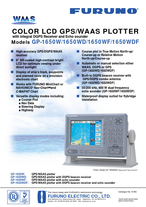
s High-accuracy GPS/DGPS/WAASreceivers 6" AR-coated high-contrast brightLCD for optimum viewing under direct sunlights Display of ship's track, waypointsand planned route on a precision electronic charts Works with FURUNO MiniChart orNAVIONICS ®Nav-Chart and C-MAP NT Charts Versatile display modes including:qCourse Plot q Nav Dataq Steering Display q Highways Course plot in True Motion North-up/Course-up or Relative Motion North-up/Course-ups Automatic or manual selection eitherWAAS, DGPS or GPS (GP-1650WD/1650WDF)s Built-in DGPS beacon receiver withGPS/DGPS combo antenna (GP-1650WD/1650WDF)s 50/200 kHz, 600 W dual-frequencyecho sounder (GP-1650WF/1650WDF)s Waterproof display suited for flybridgeinstallationModels GP-1650W/1650WD/1650WF/1650WDFTRADE MARK REGISTERED MARCA REGISTRADACatalogue No. N-852COLOR LCD GPS/WAAS PLOTTERThe future today with FURUNO's electronics technology.FURUNO ELECTRIC CO., LTD.9-52 Ashihara-cho, Nishinomiya City, Japan Telephone: +81 (0)798 65-2111Telefax: +81 (0)798 65-4200, 66-4622 URL: www.furuno.co.jpGP-1650W:GPS/WAAS plotterGP-1650WD:GPS/WAAS plotter with DGPS beacon receiver GP-1650WF:GPS/WAAS plotter with echo sounderGP-1650WDF:GPS/WAAS plotter with DGPS beacon receiver and echo sounderPhoto: Model GP-1650WDF (Navionics ®Nav-Chart )with integral DGPS Receiver and Echo sounderOwn shipPlanned routeOwn ship's trackCursorNavionics ®Nav-ChartCompact sensitive GPS/DGPS antennaGPS/DGPS /WAAS combo antennaFor all boaters...FURUNO GP-1650 series offerAccurate Positioning with WAAS,High Contrast Bright LCD for optimum viewing under the direct sun lightThe GP-1650W series are GPS/DGPS/WAAS plotters with video plotting and echo sounding capabilitydesigned for pleasure craft and coastal fishing boats.This compact and cost-effective series offersextremely accurate position fixes - 10 m for the basic GPS, 3 m where WAAS service is available and 5 m with DGPS (DGPS version).The Display modes include Course Plot, Nav Data,Steering and Highway. The Steering mode provides an intuitive indication of course to steer and cross-track-error. The Highway mode is useful when you are following a series of waypoints along a planned route.The GP-1650WF and GP-1850WDF with the 50/200kHz echo sounder module present detailedinformation on fish and bottom. The echo sounder data can be displayed jointly with course plot or alone on the full size screen.The useable chart cards are Furuno MiniChart/Navionics ®Nav-Chart or C-MAP NT Chart cards.Chart cards contain accurate spot sounding,coastlines, depth contours, buoys, lighthouses and other navigational features.Navionics ®Nav-ChartC-MAP NT ChartC-MAP NT ChartC-MAP NT ChartC-MAP NT ChartGPS RECEIVER CHARACTERISTICS1.Receiver Type Twelve discrete channels, C/A code, all-in-viewintegral WAAS processor2.Receive Frequency L1 (1575.42 MHz)3.Accuracy GPS: 10 m (95%)DGPS: 5 m (95%)WAAS: 3 m (95%)4.Time to First Fix12 seconds typical (Warm start)5.Tracking velocity999 knots6.Geodetic System WGS-84, NAD-27, and others7.DGPS CapabilityGP-1650WD/1650WDF:DGPS beacon receiver built inGP-1650W/1650WF:External DGPS beacon receiver transmittingdata in RTCM SC104 v.2.1 format throughRS-232C interface or optional internal DGPS4.Rectifier PR-62 for 115/230 VAC mains5.Temperature Sensor T-02MTB/T-02MSB/T-03MSB (GP-1650WF/GP-1650WDF)6.Speed/Temperature Sensor ST-02MSB/ST-02PSB (GP-1650WF/GP-1650WDF)7.Internal DGPS beacon receiver kit for GP-1650W/GP-1650WF8.Connector kit for connecting temp or speed/temp sensor9.RAM cardTransducers(Specify when ordering GP-1650WF/1650WDF.)1.520-5PSD (Plastic thru-hull)2.520-5MSD (Bronze thru-hull)3.520-5PWD (Plastic transom)4.525ST-MSD (Bronze thru-hull with speed/temp sensor)5.525ST-PWD (Plastic transom with speed/temp sensor)。
推荐-运维事故报告模板 精品

运维事故报告模板篇一:运维报告XXXXX项目项目名称:(转载于:XltkWJ 小龙文档网:运维事故报告模板)建设单位:维保单位:XXX运行报告目录一、维护目的 (1)1.系统功能、性能与稳定性考核 (1)2.系统在各种环境和工况条件下的工作稳定性和可靠性 (1)3.健全系统运维管理体制,完善运行操作、系统维护规范 (1)二、运维的准备 (2)1.完成系统操作、维护人员的培训 (2)2.建立系统运行所需的各项规章制度 (2)三、运维时间范围 (2)四、运维制度 (2)1.职责划分................................................................................................. .. (3)2.规章制度................................................................................................. .. (3)3.内容记录................................................................................................. .. (3)4.问题处理方式................................................................................................. (3)五、运行情况记录表 (5)六、维护期运行情况总结.........................................................6一、维护目的运维期间通过既定时间段的运行,全面考察项目建设成果。
并通过运行发现项目存在的问题,从而进一步完善项目建设内容,确保项目顺利平稳地移交给运行管理单位。
柯尼卡美能达bizhub C250_C252维修手册中文
柯尼卡美能达bizhub C250_C252维修手册中文2006.122006.12Ver. 3.0Ver. 3.02006.12 Ver. 3.02006.12 Ver. 3.0?? 2006 ?? 2006DD4038PC3-0800DD4038PC3-0800G4G4i现场维修总目录安全和重要警告事项 ..................................................................... ....................................S-1重要注意事项 ..................................................................... .........................................S-1危险事项、警告和注意的描述 ..................................................................... ................S-1安全警告 ..................................................................... ................................................S-2机器上的警告标识 ..................................................................... ................................S-18当发生意外时采取的措施 ..................................................................... ..........................S-20维修手册的构成 ..................................................................... ..........................................C-1维修手册的注释 ................................................................. ..............................................C-2bizhubC250/C252 主机概述.................................................................. ...............................................................1维修...................................................................... ...........................................................9调整/设置...................................................................... .............................................169故障排除...................................................................... ...............................................397附标准录...................................................................... .......................................................517控制器概述.................................................................. ...............................................................1维修...................................................................... ...........................................................3调整/设置...................................................................... ...............................................37故障排除...................................................................... .................................................39DF-601概述...................................................................... ...........................................................1维修...................................................................... ...........................................................5调整/设置.....................................................................................................................13故障排除...................................................................... .................................................29PC-103/PC-203概述.................................................................. ...............................................................1维修...................................................................... ...........................................................3调整/设置...................................................................... ...............................................13故障排除...................................................................... .................................................19PC-403概述...................................................................... ...........................................................1维修...................................................................... ...........................................................3调整/设置...................................................................... ...............................................17故障排除...................................................................... .................................................25bizhubC250_FS_Total_E TOC.fm Page i Friday January 5 2007 4:11 PMiiAD-503概述...................................................................... ..........................................................1维修...................................................................... ..........................................................3调整/设置...................................................................... ................................................7故障排除...................................................................... .................................................11FS-501概述...................................................................... ..........................................................1维修.................................................................. ..............................................................5调整/设置...................................................................... ................................................9故障排除...................................................................... .................................................19FS-514/PK-510/OT-601概述.................................................................. ..............................................................1维修...................................................................... ..........................................................7调整/设置...................................................................... ..............................................45故障排除...................................................................... .................................................59MT-501 概述...................................................................... ..........................................................1维修...................................................................... ..........................................................3调整/设置...................................................................... ................................................7故障排除...................................................................... .................................................13SD-503概述...................................................................... ..........................................................1维/修...................................................................... ..........................................................3调整设置...................................................................... ..............................................25故障排除...................................................................... .................................................37FS-603概述...................................................................... ..........................................................1维修...................................................................... ..........................................................5调整/设置...................................................................... ..............................................23故障排除...................................................................... .................................................51bizhubC250_FS_Total_E TOC.fm Page ii Friday January 5 2007 4:11 PM安全和重要警告事项S-1在进行维修工作前请仔细阅读如下所述的安全和重要警告事项并充分理解其含义。
IS1650资料
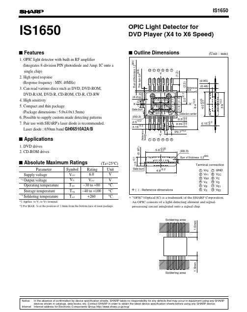
IS16501. OPIC light detector with built-in RF amplifier(Integrates 8-division PIN photodiode and Amp. IC onto a single chip)2. High speed response(Response frequency : MIN. 40MHz)3. Can read various discs such as DVD, DVD-ROM, DVD-RAM, DVD-R, CD-ROM, CD-R, CD-RW4. High s ensitivity5. Compact and thin package(Package dimensions : 5.0x4.0x1.5mm)6. Possible to supply custom-made detecting patterns7. Pair use with SHARP's laser diode is ser diode : 650nm band GH06510A2A/BOPIC Light Detector forDVD Player (X4 to X6 Speed)s Features1. DVD drives2. CD-ROM drivess Applicationss Outline Dimensionss Absolute Maximum Ratings*1 Applies to V A to V F2 terminal.*2 For MAX. 3s at the position of 1.0mm from the bottom face of resin package.ParameterSymbol RatingUnit Supply voltage V CC*1Output voltageV O V V Operating temperature T opr −30 to +80°C Storage temperature T stg −40 to +1006.0V CC °C *2Soldering temperatureT sol +260°C(Ta =25°C)∗“OPIC”(Optical IC) is a trademark of the SHARP Corporation.An OPIC consists of a light-detecting element and signal-processing circuit integrated onto a signal chip.NoticeIn the absence of confirmation by device specification sheets, SHARP takes no responsibility for any defects that may occur in equipment using any SHARP devices shown in catalogs, data books, etc. Contact SHARP in order to obtain the latest device specification sheets before using any SHARP device.Internet Internet address for Electronic Components Group http://www.sharp.co.jp/ecg/s Electro-optical Characteristics 1s Electro-optical Characteristics 2Parameter Symbol MIN.TYP.MAX.Unit Application Supply current I CC20V od1V od2V od3Conditions−A−BC−D(A+C)−(B+D)(A+D)−(B+C)(A+B)−(C+D)(E1+E2)−(F1+F2)Specified by voltage difference from VsSpecified by voltage difference from VsGND reference+25+151.55VccV A to V DV A to V DV A to V DV A to V DV A to V DV E1 to V F2V E1 to V F2V E1 to V F2V RF Output off-set voltage 1Output off-set voltage 3Output off-set voltage 28.8−15−25−20−20−20−20−201.2514.81.4mAmVVmV∆V od(E1+F2)−(E2+F1)A+B+C+DV A, V BV C, V D Extremes of off-set voltage−15−100−15−20−20−20−20−20−15−100−15mV(Ta=25°C, Vcc=5V, V S=2.1V, R L=10kΩ [V RF : Open], C L=10pF)−f=23.1MHz, BW=30kHzf=23.1MHz, BW=30kHzOutput noise level 1Output noise level 2V RFV A to V D−−70−61V n1V n2−81−72dBmdBmV RFV RFV RFV A to V DV A to V DV E1 to V F2V E1 to V F2 Parameter Symbol MIN.TYP.MAX.Unit Application Sensitivity 1R p1−−−−−−−−−−−−−−−32.3R p2R p3∆R p1R p2/R p1R p3/R p1V OH1V OH2Conditions−−−−−−f=1 to 23.1MHzf=1 to 23.1MHz, Average of V A to V D−3dB−3dB−3dB58.139.710%VV1.053436218.631.221.325.544.730.51.811.18 1.3050604mV/µWmV/µWmV/µW(Ta=25°C, Vcc=5V, V S=2.1V, R L=10kΩ [V RF : Open], C L=10pF)*3, *4Sensitivity 2Sensitivity ratio 1Sensitivity ratio 2*3, *4Sensitivity 3*3, *4Extreme of sensitivity 1*5High level output voltage 1High level output voltage 2*4*4V A to V DV RFV A to V D−−−f c1f c2f c3tgd1tgd2−−3.83.82.52.566nsnsMHzMHzMHz Response frequency 1*4, *6Group delay deviation 1*4, *7Group delay deviation 2*4, *7Response frequency 2*4, *6Response frequency 3*4, *6Input light source wavelength λp=780nms Recommended Operating ConditionsParameter MIN.TYP.MAX.UnitSupply voltage 1Supply voltage 25.25SymbolV ccV S VV5.02.1 2.24.752.0(Ta=25°C)s Electro-optical Characteristics 3*3 5µW, φ30µm of DC light is applied to the center of each photodiode.Under that condition, sensitivity R p is shown by following formula.R p =(V p −V od )/10µWV p : Output voltage when DC light is applid.V od : Output voltage when DC light is not applied.*4 Light source : laser diode of λ=650nm or 780nm.*5 Extreme of sensitivity is shown by following formula.2 x (R p1max.−R p1min.) / (R p1max.+R p1min.) x 1002 x (R p2max.−R p2min.) / (R p2max.+R p2min.) x 1002 x (R p4max.−R p4min.) / (R p4max.+R p4min.) x 1002 x (R p5max.−R p5min.) / (R p5max.+R p5min.) x 100*6 Frequency sensitivity is −3dB. (reference sensitivity : value at f =1MHz)*7 In addition to 10µW, φ30µm DC light, 4µWp-p AC light is applied to the center of each photodiode. BW =10kHz *8 For Frequency Charactoristics refer to Fig.1.*9 As the temperature characteristics of the peaking rate A, the peaking rate at Ta=65˚C against the peaking rate at Ta=25˚C shall be satisfied with the change rate Max. 2.5dB.(Application terminal : VA to VD, VRF)V RF V RF V RF V A to V D V A to V D V E1 to V F2V E1 to V F2Parameter Symbol MIN.TYP.MAX.Unit Application Sensitivity 4R p4−−−−−−−−−−−−−−−27.0R p5R p6∆R p2R p5/R p4R p6/R p4V OH3V OH4Conditions −−−−−−f =1 to 23.1MHz f =1 to 23.1MHz, Average of V A to V D −3dB −3dB −3dB 47.437.210%V V1.054040215.525.420.021.336.425.01.811.18 1.3055654mV/µW mV/µW mV/µW (Ta =25°C, Vcc =5V, V S =2.1V, R L =10k Ω [V RF : Open], C L =10pF)*3, *4Sensitivity 5Sensitivity ratio 3Sensitivity ratio 4*3, *4Sensitivity 6*3, *4Extreme of sensitivity 2*5High level output voltage 3High level output voltage 4*4*4V A to V D V RF V A to V D −−−f c4f c5f c6t gd3t gd4−− 3.83.83377ns ns MHz MHz MHz Response frequency 4*4, *6Group delay deviation 3*4, *7Group delay deviation 4*4, *7Response frequency 5*4, *6Response frequency 6*4, *6Input light source wavelength λp =650nm Fig.1 Frequency CharacteristicsFig.2 Detecting Pattern of Photodiode−3dBThe following 3 points shall be satisfied as frequency characteristics. (Application : fc1, fc2, fc4, fc5) (Ta =25°C, V CC =5V, V S =2.1V, R L =10k Ω [V RF : Open], C L =10pF) (Reference frequency 1MHz)No oscillation at the load condition of R L =10k Ω, C L =30pF.S e n s i t i v i t y (d B )780nm Peaking rate A MAX. 2.5dB Bottom rate B MAX. 0.5dB Change rate CMAX. 2.5dB 650nm MAX. 4.5dB MAX. 0.5dB MAX. 4.5dB(Unit : µm)Fig.6 Output Offset Voltage vs. AmbientTemperature (E, F)Fig.4 Supply Current vs. AmbientTemperatureFig.5 Output Offset Voltage vs. AmbientTemperature (A to D)Fig.7 Output Offset Voltage vs. AmbientTemperature (RF)Fig.3 Block DiagramS V CCGNDABCDE1F2RFE2F1S u p p l y c u r r e n t I C C (m A )17.016.516.015.515.014.514.013.513.012.5Ambient temperature Ta (°C)12.0O u t p u t o f f s e t v o l t a g e V o d (m V )15Ambient temperature Ta (°C)−151050−5−10O u t p u t o f f s e t v o l t a g e V o d (m V )15Ambient temperature Ta (°C)−151050−5−10O u t p u t o f f s e t v o l t a g e V o d (V )2.0Ambient temperature Ta (°C)1.91.81.71.61.51.41.31.21.11.0Fig.10 Sensitivity vs. Ambient Temperature(A to D)Fig.9 Response Frequency vs. AmbientTemperature (RF)Fig.11 Sensitivity vs. Ambient Temperature(RF)Fig.8 Response Frequency vs. AmbientTemperature (A to D)R e s p o n s e f r e q u e n c y f c (M H z )3080757065605550454035Ambient temperature Ta (°C)R e s p o n s e f r e q u e n c y f c (M H z )3080757065605550454035Ambient temperature Ta (°C)S e n s i t i v i t y R p (m V /µW )2030292827262524232221Ambient temperature Ta (°C)S e n s i t i v i t y R p (m V /µW )2535343332313029282726Ambient temperature Ta (°C)Application CircuitsNOTICEq The circuit application examples in this publication are provided to explain representative applications of SHARP devices and are not intended to guarantee any circuit design or license any intellectual property rights. SHARP takes no responsibility for any problems related to any intellectual property right of a third party resulting from the use of SHARP's devices.q Contact SHARP in order to obtain the latest device specification sheets before using any SHARP device.SHARP reserves the right to make changes in the specifications, characteristics, data, materials, structure, and other contents described herein at any time without notice in order to improve design or reliability. Manufacturing locations are also subject to change without notice.q Observe the following points when using any devices in this publication. SHARP takes no responsibility for damage caused by improper use of the devices which does not meet the conditions and absolute maximum ratings to be used specified in the relevant specification sheet nor meet the following conditions:(i) The devices in this publication are designed for use in general electronic equipment designs such as:--- Personal computers--- Office automation equipment--- Telecommunication equipment [terminal]--- Test and measurement equipment--- Industrial control--- Audio visual equipment--- Consumer electronics(ii)Measures such as fail-safe function and redundant design should be taken to ensure reliability and safety when SHARP devices are used for or in connection with equipment that requires higher reliability such as:--- Transportation control and safety equipment (i.e., aircraft, trains, automobiles, etc.)--- Traffic signals--- Gas leakage sensor breakers--- Alarm equipment--- Various safety devices, etc.(iii)SHARP devices shall not be used for or in connection with equipment that requires an extremely high level of reliability and safety such as:--- Space applications--- Telecommunication equipment [trunk lines]--- Nuclear power control equipment--- Medical and other life support equipment (e.g., scuba).q Contact a SHARP representative in advance when intending to use SHARP devices for any "specific"applications other than those recommended by SHARP or when it is unclear which category mentioned above controls the intended use.q If the SHARP devices listed in this publication fall within the scope of strategic products described in the Foreign Exchange and Foreign Trade Control Law of Japan, it is necessary to obtain approval to export such SHARP devices.q This publication is the proprietary product of SHARP and is copyrighted, with all rights reserved. Under the copyright laws, no part of this publication may be reproduced or transmitted in any form or by any means, electronic or mechanical, for any purpose, in whole or in part, without the express written permission of SHARP. Express written permission is also required before any use of this publication may be made by a third party.q Contact and consult with a SHARP representative if there are any questions about the contents of this publication.。
EMC产品介绍

Direct Attached Storage (DAS)
Host
H B A H B A H B A H B A
SP A LUN 0 LUN 1 LUN 2 LUN 3 LUN 4 LUN 5 LUN 6 LUN 7
SP B
CX400 Hardware & Software Overview 20
(3) Power Supply Fault LED (5) Enclosure Addressing Switch (1) Power Connector & Switch Power Supply A
Power Supply B
(4) Power OK LED
(2) Blower Fault LED
©版权所有 2007 EMC 公司。保留所有权利。
5
CX400 Array Backend Configurations
15 drives (12 volt only) maximum per enclosure – Minimum 4 drives per array, 5 for write caching 60 drives maximum per array 60 RAID groups per array – RAID types of 0, 1, 1/0, 3, 5, single disk and global hot spare. 32 LUNs per RAID group/512 LUNs per array – Minimum LUN size 1 MB – Maximum LUN size 2 TB – 256 Luns per initiator
CX400 is to CX600 as FC5300 was to FC5700
05-风机数据通信基础知识
孙伟
1
风机数据通信基础知识
主要学习内容 :
1. 数据通信的物理介质 2. 计算机数据通信网络拓扑结构及SCADA系统 3. 1500kw风机的通信网络结构 4. 光纤通信及相关知识
1.数据通信的物理介质
有线 同轴电缆 双绞线 光纤
无线 卫星 无线电波 红外通信 激光通信 微波
双绞线:
(a) Category 3 UTP. (b) Category 5 UTP.
双绞线
同轴电缆
光缆
电信号传输和光信号传输的差别
电信号 1.传输距离有限 2.易受干扰,雷击。 3.通讯网络成本相对较低。 光信号 1.传输距离远 2.抗干扰性强,不会被雷击。 3.组网成本相对较高
风机通讯中常用的光缆是: GYTA53-4B GYTA53表示: 金属加强构件、带铠装、通信 用室外光缆。 4B表示: 单模4芯光纤。 将B换为A则为多模。
第七步:包装工作 熔接完的光纤玻璃丝还露在外头,很容易折断。这时候就可以使用
刚刚套上的光纤热缩套管进行固定了。将套好光纤热缩套管的光纤放到 加热器中按 “HEAT” 键开始加热,(如下图)过 10 秒钟后就可以拿出 来了,至此完成了一个线芯的熔接工作。最后还需要把熔接好的光纤放 置固定在光纤收容箱中。
交换机
光纤
风 机
交换机
光纤
光纤
交换机
网线
服务器
LM系列交换机是菲尼克斯电气最新推出的宽温网管型交换机。它 的工作温度适用范围极宽,可用于国内各地区、各种恶劣环境。 这种交换机还具备网管功能,可以方便的对网络进行设置、调试 和检测。同时这款交换机还具备升级功能,可方便的从菲尼克斯 电气网站上免费下载相应的升级包。
- 1、下载文档前请自行甄别文档内容的完整性,平台不提供额外的编辑、内容补充、找答案等附加服务。
- 2、"仅部分预览"的文档,不可在线预览部分如存在完整性等问题,可反馈申请退款(可完整预览的文档不适用该条件!)。
- 3、如文档侵犯您的权益,请联系客服反馈,我们会尽快为您处理(人工客服工作时间:9:00-18:30)。
*******************************************************************************************************************************************************
OPTOWA Y TECHNOLOGY INC. No .38, Kuang Fu S. Road, Hu Kou, Hsin Chu Industrial Park, Hsin Chu, Taiwan 303
1650 nm DFB LASER DIODE MODULE DL-5300S-1650 Series
UNCOOLED MQW DFB LD WITH PIGTAIL
*******************************************************************************************************************************************************
FEATURES
² 1650 nm Uncooled Laser Diode with MQW Structure ² High Reliability, Long Operation Life
² Single Frequency Operation with High SMSR ² Speed up to 2.5 Gbps
² 0 to 70o C operation without active cooling ² Build-in InGaAs monitor
APPLICATION
Trunk Line, OTDR
DESCRIPTION
DL-5300S-1650 series are designed for coupling a single mode optical fiber with 1650 nm MQW DFB uncooled laser diode. These modules are ideally suitable for long reach and intermediate reach OC-3, OC-12, and OC-48 transmission application.
ELECTRICAL AND OPTICAL CHARACTERISTICS (T C =25 °C)
Symbol Parameter
Test Conditions
Min. Typ. Max. Unit I th Threshold Current CW
10 15 mA V OP Operating V oltage
CW, I F = I th +25mA
1.2 1.5 V P f
Optical Output Power Part No: DL-532XS-1650 DL-533XS-1650 CW, I F = I th +25mA 1.0 2.0
mW λc Center Wavelength CW, Po= P f 1640 1650 1660 nm SMSR Side Mode Suppression Ratio CW, I th +25mA 30 35 dB t r , t f Rise And Fall Times I F =I th , I th +25mA , 20~ 80% 150 ps ΔP f / P f Tracking Error APC, 0~+70 ºC - - ±1.5 dB I m PD Monitor Current CW, I th +25mA ,V RD =1V 100 1500 μA I D
PD Dark Current
V RD =5V
0.1
μA
C t
PD Capacitance
V RD =5V , f=1MHz
10 15 pF
ABSOLUTE MAXIMUM RATINGS (T C =25 ºC)
Symbol Parameter
Ratings Unit P o Optical Output Power (532XS/533XS) 1.5/3 mW V RL LD Reverse V oltage 2 V V RD PD Reverse V oltage 10 V I FD PD Forward Current 1.0 mA T opr Operating Temperature 0 to 70 ºC T stg
Storage Temperature
-40~+85
ºC
*******************************************************************************************************************************************************
OPTOWA Y TECHNOLOGY INC. No .38, Kuang Fu S. Road, Hu Kou, Hsin Chu Industrial Park, Hsin Chu, Taiwan 303
ORDER INFORMATION
Part No.: D L − 5 3 □ □ □ − 1 6 5 0 − □ □ □ □。
