GM55_材质性能说明
五金材质对照表
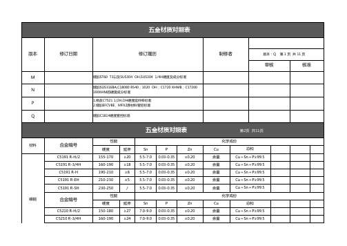
不锈钢
SUS305 1/2H 合金编号
SUS316L (美标ATSM)
SUS316L (日标JIS)
SUS316L(Apple 文件0881970-04-Type A)
SUS316L(Apple 文件0881970-04-Type B)
SUS316L OH SUS316L BA SUS316L 1/2H SUS316L 3/4H
五金材质对照表
性能
硬度
延伸
< 90
≥40
100-150
≥28
75-110
≥35
140-180
≥13
170-190
≥4
170-190
≥4
性能
硬度
延伸
250-300 10-30
270-320
8-25
280-300
8-25
300-350
5-20
310-360
3-10
320-370
/
Cu 63.5-68 63.5-68 63.5-68 63.5-68 63.5-68 63.5-68
五金材质对照表
性能 硬度 150-180 150-180 160-180 150-180 250-280 310-340 370-400 430-460 490-510
性能 硬度
延伸 ≥40 ≥40 ≥40 ≥22 ≥18 ≥12
/ / /
延伸
Si ≤1.0 ≤1.0 ≤1.0 ≤1.0 ≤1.0 ≤1.0 ≤1.0 ≤1.0 ≤1.0
300-330
≥2 0.15 max 0.15 max 13.00-15.00
化学成份
Mn
S
≤2
≤0.03
钢钣材质说明

熱軋(HR)鋼板代用原則:
圖 面 材 質 SAPH45 SAPH440 JSH440W JSH440J JSH440A JSH440B JSH440R SAPH440 P&O
1.酸洗塗油板,代用黑皮或無塗 油之酸洗板,並不影響材料性質。 2.JSH440J、JSH440R為高降伏比 板,需依SPEC要求之降伏比特別 訂購。 3.JSH440A、JSH440B為高擴孔性 板,需依SPEC要求之擴孔率特別 訂購。
SAPH32
SAPH310 JSH310W SAPH38 SAPH370 JSH370W SAPH370 P&O
SAPH310 P&O
1.酸洗塗油板,代用黑皮或無 塗油之酸洗板,並不影響材料 性質。
JSH370J
JSH370A SAPH41 SAPH400 JSH400W JSH400J SAPH400 P&O
圖面材質 SPHC SPHC-P JSH270C SPHD SPHD-P JSH270D SPHE SPHE-P SPCE-SD
SPHD P&O (1.6t(含)以上) SPCD-SD (1.5t(含)以下) SPHC P&O (1.6t(含)以上) SPCC-SD (1.5t(含)以下)
可 代 用 材 質
鋼板材質說明
一、前言
汽車所使用之鋼鐵材料包含薄鋼
板、鋼管、條鋼及鑄鐵等,佔整 車重量的70~80%,而一部汽車共 需約3萬多個零件組裝而成,根據 日本自動工程組織(JASO)的調查, 小型車所使用材料中,鋼材佔 72.3%。
由於世界各先進國家於汽車相關環保
與安全法規要求不同,導致各國在汽 車設計理念與用料規範有差異,而自 成獨立的供料體系。日本各大車廠與 各大高爐於1990年起開始進行共通性 汽車用薄鋼板規範之規劃,於1996年 完成全系列汽車用薄鋼板之“日本鐵 鋼聯盟規範(JFS)”而中鋼亦自2003年 起逐步推行,亦保留JIS規範(日本工業 標準)。
模具中的常用材料

Si 0.85~1.15
铸1.2333(锻 1.2358)
0.57~0. 61
铸1.2370(YBD-3) 0.9~1.0
(锻1.2363)
5
Cr12MoV锻
1.451. 70
铸1.2382(锻 1.2379)
1.5-1.6
0.25~0.45 0.20~0.40 ≤0.4
0.5-0.8
Mn 0.65~1.05 0.70~0.90 0.40~0.70 ≤0.35
表面淬火 HRC56以上 整体,表面 感应HRC58-
62
《模具中的常用材料及设计中应注意的一些加工问题》
材料
税前价 格/ 公斤
Cr12Mo1V1( 类 似于SKD11) 德国牌号1.2379 (相应铸态牌
号1.2382)
SKD11 :59.83
Cr12MoV
14.96
DC53
70
7CrSiMnMoV (相应铸态牌
1.2333
铸态材料对照表
热处理
用途
底板、压料板、压料圈基体、驱 动块、带导板的CAM滑块
退火硬度
FH/IH 50-54 IH 54-58
拉延凸模、压料圈
驱动块、不带导板的CAM滑块\单 薄底板、压料板
耐磨损的拉延凸模、压料圈、凹 模
FH/IH 50-54 IH/H 58-62 FH/IH 54-56 IH 56-60
单薄压料板
滑块等
整形大凸模、凹模
料厚超过1.5或翻边高度超过25的 翻边凹模,拉延模镶块
供货状态 硬度(HBS)
灰铸铁
HT250 /HT300
球墨铸铁
QT400(不常用, 可用
QT500代 替)
GPI GM系列说明书

!-
#43;
2
+
R
+
4
+
1
+
1
(
!)
*
!" PPS
BUY SMART.BUY VALUE.BUY
ML-1800-3 09/04
25
SECTION 3: GM SERIES - OVAL GEAR METERS
!"#$%&
➤
➤
➤
➤
➤
➤
➤
!"#GM
GM
!"#$
!"#$%&'()*$+,-./0123456789:;<=>?@ABCD !"#$%&'()*+,-./0 123456GM !"#$%&GM !"#$%&'()*+,-./0123456
!
2 = PPS 3 4 5
( GM002*, GM003*, GM005, GM007*, GM010, GM015, GM020, GM505, GM510, GM515 & GM520) = PPS (GM005, GM010, GM015, GM020, GM505, GM510, GM515 & GM520) = (GM001, GM002, GM003, GM005, GM010, GM015, GM020, GM510, GM515 & GM520) = S.S. (GM003, GM005, GM010, GM015, GM020, GM510, GM515 & GM520)
GM
!
GM55_材质性能说明
1.80
230
127
銅 Cupper 鋼 Steel ステンレス Stainless Steel SUS304½ H
8.90 7.85 7.90
343 412 834
39 52 106
チタン Titanium
4.5
392
9 87 8
◆Comparisons
1. Weight (g)
Material
4
Confidential and Proprietary Information
GM55 Replace the SUS:
<1>SHARP
SH907(D) JA-03(S) EB-4045 SUS304 800MPa 625MPa
MP
<2>Panasonic
GM55-H38 410MPa 310 M Pa <3>NEC CYCLONE
●卯釘 : 扭力& 拉力 SUS >GM 55
11
Confidential and Proprietary Information
5. Reliability Test
●Salt Test : 48 HR pass
12
Confidential and Proprietary Information
( as .Page 2 )
Material SUS-3D GM55-H38
平面度(0.2/0.3 mm)
扭力(3KG)
拉力(10KG)
0.25
3 kg
15 kg
0.25
2 kg
13 kg
●Flatness : Under <=0.3 mm (P1,P2,P3,P4,P5,P6)
冷冲压模具材料的化学成分及机械性能

冷冲压模具材料的化学成分及机械性能模具焊接用焊条情况焊条各种模具使用TIG焊丝铸铁用焊条铸铁型面用及堆焊焊条DMA-100 铸铁修补接合使用铜合金硬面堆焊焊条2模具在汽车、运输、机械、电器产品、家庭用品、办公用品、光学器材、玩具、建材、航空等几乎所有行业中都有应用,做为产品大量生产的母体手段,日益发挥着重要作用,为保证工厂的生产效率和产品质量方面的要求,对各种模具在经久耐用、生产精度上的要求更加严格。
但是由于磨损、尺寸变更、加工错误、缺损等原因,而在模具生产上产生的高成本,往往令企业难以接受。
而采用焊接修补方式可以使成本大大降低,同时又不影响生产。
即使是造价便宜的模具,采用修补方式,也会将原来的使用寿命提高1—2倍。
而模具修补往往需要高级技术、高档材料且工艺复杂,不是一般企业都能够掌握的。
本公司已多年修补模具的经验为后盾,可根据客户的要求、母材材质、使用条件及形状等复杂条件,为客户选用经济实用、材质匹配的模具专用焊接材料,并长期提供技术支持,我们的焊接材料适用于冲压模、拔丝模、连铸模、塑胶模、锻造模等冷热作模具刃口工具等。
冷作冲压模具使用焊接材料应用规范及注意事项专用焊条冲压模具母材,由于现在的主流为合金工具钢或铸铁,施焊相对于碳钢来讲,非常的困难,会出现各种问题。
合金工具钢含碳量和其它元素较多,为较易淬火材料,焊接时多发生裂纹。
这是模具钢本身所要求的材料特性所决定的。
另一方面,铸铁自身的延伸率较差,焊接时热输入容易引淬硬和开裂,同时易产生气孔,为较难焊接材料。
鉴于上述原因,模具钢的焊接非常困难,我们应该注意如下事项:1.1.为防止开裂,应依据模具钢母材或焊接材料,进行预热并控制层间温度。
必要时进行后热并缓冷。
2.2.预热尽可能将温度控制在均一的水平,只能进行局部预热的情况下,在焊接部周围50mm的范围内均一加热;加热时使用长而弱的火焰,在大面积范围内缓慢地加热到100℃左右。
3.3.为了防止气孔的发生,要完全清除焊接部的锈迹、油污,使用焊条要烘干。
55nm ic wat 参数说明
55nm ic wat 参数说明55nm IC是一种制造工艺,指的是将集成电路上的元件和线路的尺寸缩小到55纳米的尺度。
本文将从工艺参数的角度来说明55nm IC的特点和优势。
55nm IC制造工艺的一项重要参数是晶体管的尺寸。
晶体管是集成电路的基本构建单元,其尺寸的缩小可以提高集成度和性能。
在55nm工艺下,晶体管的尺寸可以实现大幅度的缩小,从而使更多的晶体管可以集成到同一块芯片上。
这不仅提高了集成电路的功能,还减小了芯片的体积,使得电子设备可以更加小型化。
55nm IC的另一个重要参数是工作电压。
随着工艺的进一步缩小,集成电路的工作电压也可以相应地降低。
较低的工作电压可以降低功耗,提高电池续航时间,减少电子设备的发热量。
同时,较低的工作电压还可以提高集成电路的抗干扰能力,提高系统的稳定性和可靠性。
55nm IC的制造工艺还可以实现更高的集成度和更高的频率。
通过缩小晶体管和线路的尺寸,可以在同一块芯片上集成更多的功能单元。
这使得集成电路的功能更加丰富,可以实现更多的应用。
同时,缩小尺寸还可以提高信号传输速度,使得集成电路可以工作在更高的频率下。
这对于需要高速数据处理的应用来说非常重要,如通信设备、计算机处理器等。
55nm IC的制造工艺还可以提供更好的功耗和性能平衡。
随着工艺的进一步缩小,晶体管的漏电流也会增加,导致功耗的增加。
然而,在55nm工艺下,制造工程师采取了一系列的优化措施,如引入高介电常数材料、改进晶体管结构等,以降低漏电流和功耗。
这使得55nm IC可以在较低功耗的同时保持良好的性能,满足不同应用的需求。
55nm IC的制造工艺还具有良好的可靠性和稳定性。
制造工程师对制程参数进行了精确控制,确保了芯片的质量和可靠性。
同时,55nm工艺还引入了一些新的材料和工艺步骤,提高了集成电路的稳定性和抗干扰能力。
这使得55nm IC可以在复杂的电磁环境和恶劣的工作条件下正常工作。
55nm IC制造工艺具有晶体管尺寸缩小、工作电压降低、集成度和频率提高、功耗和性能平衡、可靠性和稳定性优良等特点和优势。
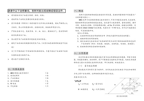
GM55数字高斯计使用说明书
产生的磁场(例如:除铁器、磁选机、永磁吸盘、电磁铁、退磁器); 4、铁磁物质的剩余弱磁场环境磁场。
二、工作原理
本系列仪器采用的传感器是基于霍尔效应原理制成的传感器,即霍尔传感 器。传感器有横向、轴向两种,用户可根据需求选择或另外配置。电路采用低漂 移的放大器以及高稳定度的供电电源、单片机控制、4½液晶显示。
图1 图2
图3
三、主要技术指标
量程范围 不确定度 灵敏度 被测磁场
应用举例
磁场频率 环境温度 相对湿度 供电电源 外型尺寸 仪器重量 显示方法
0~200~2000mT ±5%,±5 个字 0.01mT、0.1mT 交流、直流磁场 永磁材料表面磁场、铁磁物质表面剩余磁场、直流电机、扬声器、 磁选机、永磁除铁器的工作磁场、交流中频磁场、电磁炉工作磁场 DC~200Hz(参考值)
使用或保存本产品。 Ø 务必遵守本产品的使用环境温度及相对湿度。 Ø 避免产品表面出现凝露时使用本产品。(从寒冷地急速转移到温室中易出
现) Ø 为了尽可能的减少外部磁场对机器的影响,尽量不要在产生磁场干扰的
仪器附近进行检测产品。 Ø 建议客户定期进行校准。
六、仪器成套性
1、GM55 便携式数字高斯计
仪器功能键说明
ON/OFF: 电源开关 ZERO/RESET:置零开关 REAL/HOLD:锁定切换 RANGE:量程切换 AC/DC:直流/交流转换 mT/Gs:单位转换转换
8、选择峰值保持测量 当重复按峰值保持测量按键○3 时,可选择普通测量或峰值保持测量。
9、将霍尔传感器保护套旋开(见上图),然后使霍尔传感器有效位置○10(横 向传感器)或者○11 (纵向传感器)紧密接触被测材料表面(直流磁场)或被测 的磁场位置(空间交直流磁场)进行测量,液晶显示○2 即为被测磁场的大小。
模具用非标零件材质

模具用非标准零件材质2013‐03‐05模具用铸件材质铸件材质:一般分为:灰口铸铁、球墨铸铁、合金铸铁铸件材质般分为灰铸铁球墨铸铁合金铸铁、铸钢常见灰铁:HT250(FC250)、HT300(FC300/GM238)常灰铁)常见球铁:FCD550、QT600(FCD600)QT700(FCD700/GM338)常见合金铸铁:GM241(MTMoCr/FC25MoCr),GM246常见铸钢)常见铸钢:ICD5、GM190(G50CrMo4)、G20Mn5中国材质日本材质北美材质欧洲材质铸件用途:模具用铸件材质铸件用途灰铁:FC250、FC300,模具基本材料,一般用于模架,支撑垫块等球铁:FCD550、FCD600,主要用于普通薄钣材的成型,整形钢块;FCD700主要用于中强薄钣材钢的拉伸模(凸模/凹模/压边圈)合金铸铁:GM241、GM246主要用于普通薄钣材的拉伸模(凸模/凹模/压边圈)铸钢:ICD5、GM190(G50CrMo4)主要用于一般钣材的翻边刃及切边刃也可用于中强薄钣材钢的成型整形块边刃及切边刃,也可用于中强薄钣材钢的成型,整形块;G20Mn5一般用作压料板模具用铸件材质铸件热处理硬度:FC250 HRC32~42FC300 HRC40~45FCD550 HRC46~50FCD600 HRC47~53FCD700 HRC54~57GM241 HRC46~50GM246 HRC48~52ICD5 HRC 54~57GM190 HRC55~60热处理方式:火焰热处理模具用钢料材质常用钢料材质:常用钢料材质A3(SS400)、45#(S45C/1045)、1050P20(4140PH)()7CrSiMnMoV(SX105V)、HMD5Cr12、Cr12MoV(SKD11/D2/1.2379)、S7(1.2358)、O1(SKS3)、A2(1.2363/SKD12)、M2(1.3343/SKH51)中国材质日本材质北美材质欧洲材质模具用钢料材质常用钢料用途常用钢料用途:A3(SS400)、45#(S45C/1045)、1050这3种材料是钢板模具基本材料(模板,压料板,肋条,这种材料是钢板模具基本材料模板压料板肋条停止块,普通垫块等)P20(4140PH)此材料一般用于压料板窗口,导正销()此材料般用于压料板窗导销固定板,有的客户要求刀块固定块,顶料块也用此材料,材料本身经预硬化过)材料本身已经预硬化过(HRC26-30).7CrSiMnMoV(SX105V)、HMD5种材料要用切可用作成块此2种材料主要用于切刃,也可用作成型整型翻边块,此两材料均为火焰热处理材质.模具用钢料材质常用钢料用途常用钢料用途:Cr12此材料一般用于需要有硬度的垫板(如刀块垫板)板Cr12MoV(SKD11/D2/1.2379)、S7(1.2358)这2种材料主要用于成型,翻边,整型,切边块,均为真空热处理材料O1SKS3此材料一般用于需要有硬度的垫板(如刀()块垫板)和需要带硬度的耐磨钢块,为真空热处理材料()()A21.2363/SKD12、M21.3343/SKH51此2种材料一般用于标准件材质(如标准冲头,凹模套,导正销等)等模具用钢料材质钢料热处理硬度:7CrSiMnMoV HRC50~55HMD5HRC52~61Cr12HRC50~55SKD11HRC55~63S7HRC53~57O1HRC54~58A2HRC55~63M2HRC61~64热处理方式:7CrSiMnMoV,HMD5火焰热处理其余为真空热处理。
AICA 微球体粉末学习报告2016.7
AICA 微球体原料学习报告 --王海文
一. GANZPEARL主要介绍四大类微球体粉末原料
1. GM 系列 (PMMA类)
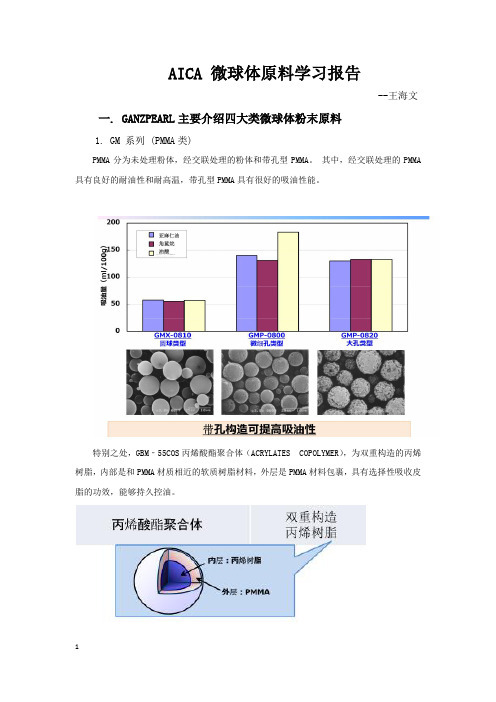
PMMA分为未处理粉体,经交联处理的粉体和带孔型PMMA。
其中,经交联处理的PMMA 具有良好的耐油性和耐高温,带孔型PMMA具有很好的吸油性能。
特别之处,GBM‐55COS丙烯酸酯聚合体(ACRYLATES COPOLYMER),为双重构造的丙烯树脂,内部是和PMMA材质相近的软质树脂材料,外层是PMMA材料包裹,具有选择性吸收皮脂的功效,能够持久控油。
2. GS 系列(聚苯⼄烯类)
聚苯乙烯具有良好的耐油性,有良好的遮盖效果,能够持久保持自然妆效。
3. SI 系列(有机硅类)
有机硅类微球体包含硬质有机硅粉和硅弹性体。
其中,硅弹性体质地柔软,分散性好,高吸油性能,消除成分油产⽣的过油现象,达到⼲爽效果。
4. GPA系列 ( 尼龙类 )
尼龙-12,柔软的微球体粉末,有很好的吸油性能。
二. 产品使用感比较
三. 化妆品推荐应用。
模具中的常用材料

模具中的常用材料及设计中 应注意的一些加工问题
技术研发部 邓燕 2011-4-10
《模具中的常用材料及设计中应注意的一些加工问题》
模具中的常用材料
材料
税前价 格/公斤
HT250 HT300
ZG45
5.73 5.73
6.41
球铁QT500 球铁QT600、
表面火焰 HRC55以
上
整体 HRC58-62
《模具中的常用材料及设计中应注意的一些加工问题》
材料
税前价 格/ 公 斤
T8A
20钢
4.70
45钢
4.02
A3(另名 Q235A)
3.85
特性 低耐磨
选用范围 常规结构件选材
主要用于垫片。
渗碳钢 主要用于导柱、大型导正销、浮动楔套筒等。
主要用于压料板,小模架、冲头固定板等。 下料后需退火,
淬火后变形较大,高精件需火后型面加工,刀 具损耗较大。用于镶块时要按项目要求选 用,现主要用于垫片、导向块等。
空冷 水冷
热处理
备注
长与宽或 高的最小 值比例
整体 HRC58-62
整体 HRC58-62
整体 HRC58-62
表面火焰 HRC55以
上
最小值 =60mm;
L:
60≤2.5 最小值 =80mm; L:80≤3 最小值 =100mm; L:100≤4
焊接性能不如A3。 主要用于不需要一定硬度和耐磨的地方,如
压料板、垫片、安装板。 焊接性能良好,因此一般焊接合件均为A3。
淬火 介 质
水冷
水冷
热处理
整体 HR C58 -62
GM55系列规格书
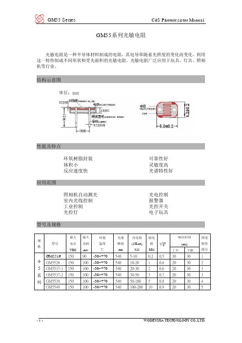
GM55系列光敏电阻光敏电阻是一种半导体材料制成的电阻,其电导率随着光照度的变化而变化。
利用这一特性制成不同形状和受光面积的光敏电阻。
光敏电阻广泛应用于玩具、灯具、照相机等行业。
结构示意图单位:mm性能及特点环氧树脂封装可靠性好体积小灵敏度高反应速度快光谱特性好应用范围照相机自动测光光电控制室内光线控制报警器工业控制光控开关光控灯电子玩具型号及规格规格型号最大电压VDC最大功耗mw环境温度℃光谱峰值nm亮电阻(10Lux)KΩ暗电阻MΩ响应时间(ms)照度特性图号上升下降φ5系列GM5516150 90 -30~+70540 5-10 0.2 0.5 30 30 1 GM5528 150 100 -30~+70540 10-20 1 0.6 20 30 2 GM5537-1 150 100 -30~+70540 20-30 2 0.6 20 30 3 GM5537-2 150 100 -30~+70540 30-50 3 0.7 20 30 3 GM5539 150 100 -30~+70540 50-100 5 0.8 20 30 4 GM5549 150 100 -30~+70540 100-200 10 0.9 20 30 5测试条件最大外加电压:在黑暗中可连续施加给元件的最大电压; 暗电阻: 关闭10Lux 光照后第10秒的阻值; 最大功耗: 环境温度为25℃时的最大功耗;亮电阻: 用400-600Lux 光照射2小时后,在标准光源(色温2854K )10Lux 光下的测试值; γ值: 10Lux 照度和 100Lux 照度下的标准电阻值之比的对数。
Lg (R10/R100)γ= =Lg(R10/R100)Lg (100/10)R10、R100 分別为10Lux 、100Lux 照度下的电阻值(γ的公差为±0.1)主要特性曲线光照度-电阻特性曲线图1 图2温度(℃) 温度特性曲线 光谱响应特性曲线相对灵敏度(%)波长λ(nm )电阻变化率(%)图3 图4图5 图6 注意事项本产品采用环保材料包装,小包装200支,大包装2000支;避免将本产品放在潮湿、高温环境下保存;焊接时间尽可能短;注意引线焊接位置应距陶瓷基座4mm以上。
全套机械密封件说明

GM37G系列机械密封件本系列属单端面密封,非平衡型符合DIN24960标准适用于水泵、污水泵、油泵、化工泵及潜水泵等。
一、概述:本系列属单端面密封,非平衡型符合DIN24960标准适用于水泵、污水泵、油泵、化工泵及潜水泵等。
二、主要技术参数压力:≤1.2MPa温度:-30℃~200℃转速:≤3000R/min密封介质:水、污水、油及一般腐蚀性液体中使用GM121系列机械密封件本系列适用于污水、油类及一般弱腐蚀介质,静环有石墨环、硬质环、碳化硅环。
概述:本系列适用于污水、油类及一般弱腐蚀介质,静环有石墨环、硬质环、碳化硅环。
如果使用在较强的腐蚀性介质,可以改O型圈为F4V型圈。
本系列机械密封系YM120型改进型,改动环为O型圈调节型,利用弹簧座上的二只肖钉套在叶轮上的传动,使密封的左右旋得已控制,可以任意旋向,可以采用左图中的静环尺寸,安装更简单。
注:静环可以采用左边总图中的形式,且安装长度应为L尺寸减L2尺寸加起H尺寸等于总长。
1.静环O型圈2.静环座3.静环4.动环5.动环O型圈6.动环座7.传动座8.弹簧9.石墨静环或碳化硅静环 10.静环橡胶座主要技术参数适用压力:≤1 Mpa适用温度:-20℃~180℃电机转速:轴径≤45≤3000转/分轴径≥50≤1450转/分GM122系列机械密封件M122系列机械密封件是一种内装内流单端面单弹簧非平衡型结构,符合ISO-3069、JB1472-75。
标准。
广泛应用于各种离心泵、化工泵、管道泵、及各种耐腐蚀泵。
一、概述:M122系列机械密封件是一种内装内流单端面单弹簧非平衡型结构,符合ISO-3069、JB1472-75。
标准。
广泛应用于各种离心泵、化工泵、管道泵、及各种耐腐蚀泵。
本系列机械密封件O型圈分丁腈橡胶、氟橡胶二种。
如果在强腐蚀性介质中使用,可以用四氟V型圈来代替橡胶O型圈,使用V型圈时,先将V型圈放在90。
C 热水中浸泡10分钟。
安装时使V型紧贴密封件内壁和泵轴,以防满泄漏。
柯尼卡美能达bizhub C250_C252维修手册中文
柯尼卡美能达bizhub C250_C252维修手册中文2006.122006.12Ver. 3.0Ver. 3.02006.12 Ver. 3.02006.12 Ver. 3.0?? 2006 ?? 2006DD4038PC3-0800DD4038PC3-0800G4G4i现场维修总目录安全和重要警告事项 ..................................................................... ....................................S-1重要注意事项 ..................................................................... .........................................S-1危险事项、警告和注意的描述 ..................................................................... ................S-1安全警告 ..................................................................... ................................................S-2机器上的警告标识 ..................................................................... ................................S-18当发生意外时采取的措施 ..................................................................... ..........................S-20维修手册的构成 ..................................................................... ..........................................C-1维修手册的注释 ................................................................. ..............................................C-2bizhubC250/C252 主机概述.................................................................. ...............................................................1维修...................................................................... ...........................................................9调整/设置...................................................................... .............................................169故障排除...................................................................... ...............................................397附标准录...................................................................... .......................................................517控制器概述.................................................................. ...............................................................1维修...................................................................... ...........................................................3调整/设置...................................................................... ...............................................37故障排除...................................................................... .................................................39DF-601概述...................................................................... ...........................................................1维修...................................................................... ...........................................................5调整/设置.....................................................................................................................13故障排除...................................................................... .................................................29PC-103/PC-203概述.................................................................. ...............................................................1维修...................................................................... ...........................................................3调整/设置...................................................................... ...............................................13故障排除...................................................................... .................................................19PC-403概述...................................................................... ...........................................................1维修...................................................................... ...........................................................3调整/设置...................................................................... ...............................................17故障排除...................................................................... .................................................25bizhubC250_FS_Total_E TOC.fm Page i Friday January 5 2007 4:11 PMiiAD-503概述...................................................................... ..........................................................1维修...................................................................... ..........................................................3调整/设置...................................................................... ................................................7故障排除...................................................................... .................................................11FS-501概述...................................................................... ..........................................................1维修.................................................................. ..............................................................5调整/设置...................................................................... ................................................9故障排除...................................................................... .................................................19FS-514/PK-510/OT-601概述.................................................................. ..............................................................1维修...................................................................... ..........................................................7调整/设置...................................................................... ..............................................45故障排除...................................................................... .................................................59MT-501 概述...................................................................... ..........................................................1维修...................................................................... ..........................................................3调整/设置...................................................................... ................................................7故障排除...................................................................... .................................................13SD-503概述...................................................................... ..........................................................1维/修...................................................................... ..........................................................3调整设置...................................................................... ..............................................25故障排除...................................................................... .................................................37FS-603概述...................................................................... ..........................................................1维修...................................................................... ..........................................................5调整/设置...................................................................... ..............................................23故障排除...................................................................... .................................................51bizhubC250_FS_Total_E TOC.fm Page ii Friday January 5 2007 4:11 PM安全和重要警告事项S-1在进行维修工作前请仔细阅读如下所述的安全和重要警告事项并充分理解其含义。
Moog System 55模块及其原始“功能描述”说明书

Moog System 55: Modules And Their Original “Functional Descriptions”.902 Voltage Controlled Amplifier: The 902 voltage Controlled Amplifier is a differential input and output circuit which gives an overall voltage gain of 2 {6dB} when the manual control potentiometer is at maximum {6}, or when a control voltage of 6 volts is applied to the control input. Maximum sum of control voltage {fixed control voltage and input jacks} is approximately 7.5 control volts, producing +4.7dB or gain of 3. Two modes of gain response are available: linear and exponential. 903A Random Signal Generator: The Random Signal Generator produces continuous bursts of random frequencies and waveshape from approximately 25Hz to 20kHz. Two types of energy distribution are provided: white noise and pink noise. The former distributes amplitude evenly throughout the indicated audio spectrum- The latter reduces the amplitude of each frequency increment proportionally to produce equal energy per octave. Pink noise, thus, sounds "lower" in pitch to the ear.904A Voltage Controlled Low Pass Filter: The 904A Low Pass Filter attenuates frequencies above the fixed control voltage cutoff point at a rate of 24dB per octave. The cutoff point {cutoff frequency} is voltage controlled through the control input jacks. The sum of the applied control voltages doubles the frequency of the cutoff point for each one-volt increase {volt per octave standardization}. The regeneration potentiometer {variable Q} varies the amount of internal feedback, creating a resonant peak at the cutoff frequency. This resonant peak will break into oscillation at clockwise settings of the regeneration pot, creating a voltage controlled sine wave generator. The fixed control voltage pot covers a 12-volt {octave} range. The overall range of the FCV pot is determined by the Frequency Range switch, which moves the frequency cutoff range in two-octave steps.The basic cutoff frequency of the Low Pass Filter is determined by the combination of fixed control voltage and frequency range in addition to the control input signals. An increase in regeneration narrows and increases the strength of the cutoff frequency peak, while decreasing the amplitude of the lower frequencies.904B Voltage Controlled High Pass Filter: The 904B Voltage Controlled High Pass Filter attenuates input signal frequencies below its nominal cutoff frequency setting. The attenuation below FCV cutoff setting is 24dB/oct. As the fundamental is generally the loudest frequency component of a complex tone, deletion of the lowest frequency range can radically alter the timbre. The FCV cutoff point is raised or lowered in octave per volt control inputs.The Frequency Range switch sets the overall range of frequencies covered by the Fixed Control Voltage potentiometer. The Low range encompasses 4hz to 20kHz, while the High range shifts 1 1/2 octaves up to 10Hz through 50kHz.911 Envelope Generators: At the introduction of a switch-to-ground {S-trigger} trigger signal from an external source, the 911 Envelope Generator produces a single voltage contour whose time/voltage variation is determined by potentiometers T1, T2, T3 and a time constant sustaining level pot {Esus}. Closure of the input trigger switch directs the voltage contour to T3 {final decay} regardless of what stage { T1, T2 or E} was in current operation. The Envelope Generator requires an S-trigger to operate. External sources must be converted to the S-trigger format via the 961 Interface.911A Dual Trigger Delay: The 911A Dual Trigger Delay is designed to be used with 2 or more 911 Envelope Generators. It provides one or two time delays on an input trigger voltage - bound for the activation of an envelope switch trigger. Three different modes of operation are available via coupling mode switch:OFF: Delays are activated independently through individual trigger inputs.PARALLEL: Trigger input to top 911A activates timing circuit on both simultaneously.SERIES: Trigger input to top 911A activates top timing circuit then triggers second upon activation of first.914 Fixed Filter Bank: Similar in function to the Moog 907A Fixed Filter Bank, the 914 Extended Range Fixed Filter Bank is a non-voltage controlled modifier with 14 separate passband controls: high pass, low pass and 12 center frequency knobs. Each passband range has an attenuation slope of 12dB per octave above or below the center frequency indicated921 Voltage Controlled Oscillator: The 921 Voltage Controlled Oscillator is a variable waveform generator, which produces frequencies ranging from .01Hz to 40kHz. Four waveforms are available: Sine, Triangular, Sawtooth, and Rectangular {with variable duty cycle}. Both fixed and variable levels can be obtained from front panel output jacks. Nominal frequency is set manually by the scale, coarse range, frequency and {octave} range controls found at the top of the module. Voltage controlled rectangular width is set by the knob in the upper center {left}, with accompanying voltage input jacks. Clamping point {waveform reset control} may be set with the lower left knob and accompanying trigger inputs to the left. Multiple frequency control inputs can be plugged into this module in parallel. All waveform outputs can be used concurrently if desired.All manual controls on this module can be moved or switched during operation. This module functions as both an audio or control voltage generator.921A Oscillator Drivers: The 921A Oscillator Driver is a control voltage processor, which drives associated 921B oscillators through internally wired connections {via edge connectors}. Two voltages are generated: one for frequency control and one for rectangular wave duty cycle. Control inputs to this module change the frequency of its associated oscillators in volt/octave increments. Manual adjustment to the Frequency and Width Of Rectangular Wave pots changes the nominal frequency and duty cycle of all connected 921B's in parallel. Two ranges are provided on the Frequency potentiometer: semitone {two octaves compass} and octave {12 octaves compass} These ranges are selected by the white switch below the Frequency potentiometer. Control inputs for frequency and rectangular width are summing.921B Oscillators:The 921B Oscillator generates frequencies from 1Hz to 40kHz minimum. They are wired in groups to a common 921A Oscillator Driver, which provides both exponential frequency control and rectangular width voltage control.Like the 921 Oscillator, this is one of the building blocks of analog synthesis. This oscillator generates both sub-audio and audio frequencies for control and audio signal use. The Frequency pot at the top of the module has a two-octave range for fine-tuning, while the Range switch shifts the frequency of the oscillator in octaves, up or down. Number indications on the Range switch correspond to traditional organ pipe range notations. Fixed level outputs for Sine, Triangle, Sawtooth and Rectangular waveforms are found at the right of the modules. DC Modulate is a linear frequency control input {does not conform to 1 volt/octave control voltage format}. AC Modulate input is a capacitor-coupled circuit like the DC Modulate input, however, blocking constant DC voltages.921B Oscillators may be phase locked together via the Synch input jack and the associated three position Synch Switch. Phase locking capability is generally limited to the first six harmonics of the input signal. A sawtooth waveform is recommended for best synchronization results.960 Sequential Controller: The 960 Sequential Controller has a wide variation of functions, both as an independent module and in combination with the 961Interface and 962 Sequential Switch.The sequencer module consists of a voltage controlled clock oscillator, which drives three rows of eight steps each. Indicatorlights show sequence and step position status. A separate potentiometer for each step permits up to eight different voltage settings to be selected for each row. The DC voltage output corresponds to the column of pots below the lighted stage. Voltagerange switches for each row determine the DC voltage range ofeach pot with two volts {X1}, four volts {X2}, or eight volts{X4} maximum extent. Two parallel outputs are provided for eachrow. Jacks for trigger inputs and outputs appear below each column. Trigger inputs activate that stage independently of theclock oscillator trigger. Trigger outputs are available for anyother V-trigger activated input. Manual trigger buttons as well,are included for each of the eight stages {found below the V-trigger jacks}. Switches found immediately below each step position permit normal, skip or stop functions. A ninth positionproviding skip {continuous progression through the eight steps}or stop {one progression to closure} functions is included at theend of the row. Timing control for the eight steps is accomplished via the Third Row Control of Timing switch. This switchconnects the third row of the sequencer into the control input ofthe clock speed for each stage according to the settings on thethird row potentiometers. The Shift input admits an externalclock input to the sequencing circuit. This input may be used inaddition to or exclusive of the internal clock oscillator trigger. Manual shift from step to step is accomplished with the button next to the shift input jack, as well as individual manual trigger buttons for each step found under each step column.Manual buttons or external v-trigger sources initiate the clock oscillator start and stop functions. The clock oscillator is capable of producing frequencies from .1Hz to 1kHz. It has both octave {range} and vernier {fine adjust} controls. One control input jack is available, as well as one rectangular wave output {approximately 90/10% duty cycle}. The clock oscillator, like other Moog oscillators, is standardized to one volt per octave.961 Interface: Four independent circuits are found on the 961 Interface: one Audio-In to V-trigger Out circuit, one S-trigger In to V-Trigger Out circuit, and two V-trigger In to S-trigger Out circuits. All interface circuits may be used simultaneously, in combination, or separately.The Audio to V-trigger circuit generates V-triggers when the audio input level rises above the threshold set on the Sensitivity potentiometer. This V-trigger sensitivity varies with the frequency band of the audio signal and with the frequency of its amplitude peaks. V-trigger duration is commensurate with the length of time the audio signal remains above the sensitivity threshold. Two parallel V-trigger outputs are included.The S-trigger to V-trigger circuits converts any Short-to-ground trigger input to a v-trigger output.Each V-trigger In to S-trigger Out circuit has two columns of six jacks each for input triggers and one S-trigger output. Column A of the V-trigger inputs will convert V-trigger signals to S-triggers with duration equal to the input. Column B determines S-trigger duration by the Switch-on-time knob ONLY. B Column S-triggers will block, extend or fore-shorten Column B V-trigger inputs to conform to whatever duration is indicated on the B-column potentiometer. A minimum switch-on-time of 40 milliseconds and maximum time of 4 seconds duration is available. Simultaneous inputs to both A and B columns may be made. Simultaneous inputs to two parallel jacks will result in the longer of the two trigger signals being accepted.962 Sequential Switch: The 962 Sequential Switch selects between two or three signal inputs, coupling one signal to the output jack at a time. A V-trigger pulse introduced to the Shift Inputinitiates the sequence. The Sequential Switch will alternate between stages One and Two, disregarding stage three until a standard {tip-sleeve} phone plug is patched into Signal Input Three. A connection to Input Three will cause the Sequential Switch to alternate between the three stages {in order) when triggered. Separate V-trigger input and output jacks are provided far each of the three stages, as well as buttons for manual switching. A small light for each stage indicates its status, on {coupled to the output} or off.992 Control Voltage Panel: The 992 Control Voltage Panel is used for routing up to four control voltage signals to the 904B Low Pass Filter. The fourth input on the panel contains a signal inverting attenuator circuit.993 Trigger and Envelope Voltages Panel: The Trigger and Envelope Voltages Panel is a signal routing module for S-triggers coming from one or two controllers. Lighted switches labeled "FROM 1" and "FROM 2" at the top of the panel connect the controller trigger outputs (when lighted) to the 911A Dual Trigger Delay. The lower three left hand column switches route the trigger signal as follows: top switch - to left 911 with no delay, center switch - to center 911 with delay set by top 911A delay unit, bottom switch - to the right 911 with delay set by the bottom 911A. The right hand green switches connect the DC control voltages from the 911's to their respective 902 Voltage Controlled Amplifiers: Left to left, center to center, right to right.994 Dual Multiples Panel: The multiple is a device, which permits multiple distribution of one signal to several different places. This process is often called signal splitting. Multiples are used for many purposes; from linking two patch cords together, sending a single signal to several different modules at the same time, to doubling or trebling the amplitude of a signal by sending it X3 to a particular source.995 Attenuator: Attenuators reduce the gain or amplitude of any applied input signal, control or audio. Moving clockwise from zero gain to unity with input, these attenuators can be used for reducing the effect of a control upon a voltage controlled module, providing up to three variable outputs from a single source input or reducing the gain of an entire signal complex.CP3A Console Panels:The CP3A module has four varied functions. The primary circuit is a 4x1 mixer with positive and negative outputs and a maximum gain of 2x. This mixer can combine both ACand/or DC voltages. The second series of functions are four signal routing switches, which connect the incoming control voltages from keyboard, ribbon or other controller units to the frequency control input of associated oscillator drivers found directly above the switching panel. The fourth input switch has both an external input jack and attenuator {found directly below}. This input jack is connected to the Oscillator Driver when the associated switch is on and the attenuator set above zero. At "10" a signal introduced here will be equal to one which is introduced directly into the frequency control inputs found on the Oscillator Driver itself. The two final elements found on the CP3A are a multiple {signal splitting - one input becomes three} and trunk line jacks, which carry a signal to the rear of the synthesizer.。
京瓷刀片涂层材质介绍

CA5515加工实例①
CA5515 300個/角
200~250個/角
其他公司涂层G
CA5515
其他公司涂层D
和现在的其他公司涂层D相比、 CA5515有高出1.5倍的加工可能
和现在的其他公司涂层D相比,不易崩损,安定性好.
中国TC
R
2005/4/27 23
京瓷最新材质 CVD涂层图片
CA4010
P05
タキノール
① 刀片紧固方式是从上面使用扳手 锁紧的 ② 2刀头样式刀片 ③ 3坐标断屑槽 ④ 最大切削径32mm ① ② ③ ④ 自锁式紧固方式 1刀头样式刀片 3坐标断屑槽 最大切削径120mm
① 切断 ・开溝用 ② 小径~大径用
ツッキール
中国TC
R
2005/4/27 32
切断工具的選択基準(小径样式)
以前的CVD涂层
采用特殊表面处理的PICA技术(Physical Innovation for Coating Advantage)实现表面超平滑。 1、除去陶瓷薄膜的损伤因素,大幅度提高刀片的安定性. 2、刃先光洁度的向上,大幅度提高刀片的耐溶着性. 3、切削抵抗降低,大幅度提高了刀片的耐摩耗性和寿命
FC
CA55 05
New Ne w CA5535
FCD350 ~FCD500
P25
CA4115
CA4120
连续 轻连续 重连续
削 材
削
P15
CA55 15 CA55 25
连续
被
材
FCD550 ~FCD700
被
P35
轻连续
重连续
加工形态
加工形态
铸铁加工用
中国TC
钢加工用
- 1、下载文档前请自行甄别文档内容的完整性,平台不提供额外的编辑、内容补充、找答案等附加服务。
- 2、"仅部分预览"的文档,不可在线预览部分如存在完整性等问题,可反馈申请退款(可完整预览的文档不适用该条件!)。
- 3、如文档侵犯您的权益,请联系客服反馈,我们会尽快为您处理(人工客服工作时间:9:00-18:30)。
●Thermal Shock Test:
12 Days Pass
13
Confidential and Proprietary Information
6. Conductivity Issue
● Measure method:最大施力Contact force至50±10g,阻抗值必須要1Ω以下 (A,B,C,D)
* 1 pcs
●CNC :0.4 t to 0.2 t ,Cycle time :60 sec ●卯釘 : GM55 easy to do than SUS
0.2mm
3.0
2.1mm
UPDATE
2.6
1.9mm
10
Confidential and Proprietary Information
4. SPEC
(1) Electrical resistivity (2) Thermal conductivity (3) Modulus of elasticity (4) Melting point (5) Density 27.2 (%IACS) 110(w/mK,@25 deg.C) 70 (KN) 575 (deg.C) 2.64 (g/cm3)
D C
A
B
14
Confidential and Proprietary Information
◆Conclusion
1. Drop Test :heigh is 110 meter . Pass 2.Bending Test : 28 kg .Pass
3.Conductivity : <1 Ω . Pass
◆化学成分 Chemical Composition
6
◆金属工業の電子產品用途 鋁合金 Aluminum Alloy for IT field
8 7
◆金属素材 (比強度)
Material 素材 Gravity 比重
PS.:單位比重的強度比較
Strength/Gravity比強度 (強度/比重)
( as .Page 2 )
Material SUS-3D GM55-H38
平面度(0.2/0.3 mm)
扭力(3KG)
拉力(10KG)
0.25
3 kg
15 kg
0.25
2 kg
13 kg
●Flatness : Under <=0.3 mm (P1,P2,P3,P4,P5,P6)
After insert mold
高強度的GM55-H38用來代替、取代SUS t0.3mm是最合適的。
手機外框、液晶部品等已有很多運用實例。 鋁材是無磁性。 對GPS是毫無任何影響。
Good for changing from SUS304-0.3t mm , for cost-down, light-weight. Very high strength 5 Aluminum GM55-H38. Aluminum never magnetized, no-effect for GPS. 5
Strength 強度 (N/㎜2)
アルミニウム Aluminum (1050-H24)
2.7
125
46
アルミニウムAluminum (5052-H34)
2.7
240
89
アルミニウムAluminum (GM55-H38)
2.7
400
148
マグネシウムMagnesium (AZ91 Die-cast)
1.80
230
127
銅 Cupper 鋼 Steel ステンレス Stainless Steel SUS304½ H
8.90 7.85 7.90
343 412 834
39 52 106
チタン Titanium
4.5
392
9 87 8
◆Comparisons
1. Weight (g)
Material
●卯釘 : 扭力& 拉力 SUS >GM 55
11
Confidential and Proprietary Information
5. Reliability Test
●Salt Test : 48 HR pass
12
Confidential and Proprietary Information
Dimension (mm) 137 *73*0.4t 137 *73*0.4t
Gravity
Weight (Kg) 0.010 0.031
Weight(g)
GM55 SUS 304
2.64 7.85
10g 31g
2. Material cost ($ )
Material SUS-3D GM55-H38 $USD $6.89 $8.5 PCS/ Cost ($ ) $0.214 $0.085
4
Confidential and Proprietary Information
GM55 Replace the SUS:
<1>SHARP
SH907(D) JA-03(S) EB-4045 SUS304 800MPa 625MPa
MP
<2>Panasonic
GM55-H38 410MPa 310 M Pa <3>NEC CYCLONE
GM55 Mobile Insert Metal
1
Confidential and Proprietary Information
2
Confidential and Proprietary Information
Rivet ●Process:連續模沖壓--->卯釘(rivet)--->清洗-->皮膜(導電) ●Capacity:40k 1 day/ 1 tooling
4.Flatness : 0.25 mm ,after insert mold .Pass
5.Salt Test :48 hour .Pass
6.Reduced the extra 2nd process.(used the Rivet to replace the laser spot)
15
Confidential and Proprietary Information
*no Ni Plate
差異:0.129
9
Confidential and Proprietary Information
3. Process cost ( as .Page 2 )
Material
SUS-3D GM55-H38 Nhomakorabea卯釘$0.0
CNC
$0.2
雷焊
$0.3
$0.03
$0.15
$0.0 3.0 mm
●Tooling L/T :15 days ,For T0 ●T2 ,we can lock down if no ECN 3 Confidential and Proprietary Information
Mechanical Properties
Typical physical properties:
