使用串口更新image
谱泰通信科技PTC08串口摄像头使用说明书
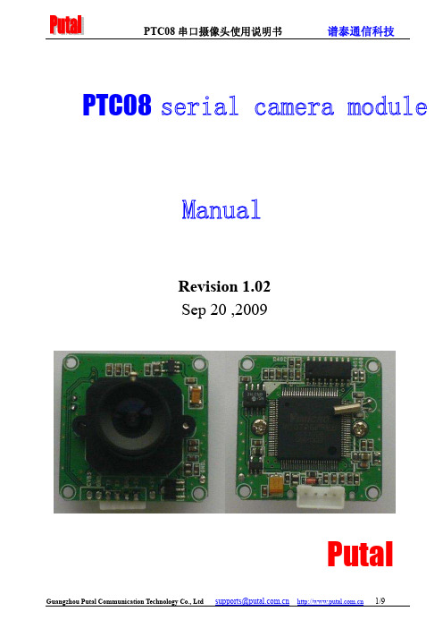
PTC08Revision 1.02Sep 20 ,2009Putal目录1 PTC08PTC08 Serial Camera Introduction (3) (3)2.Key performance indicators (4)3.camera interface description4.Camera protocol (7) (7)4.1Reset Command (7)4.2Camera instruction4.3Reading the film images length instruction (7) (7)4.4Reading the film images data instructions (7)4.5Stop taking commands4.6Instruction Set camera picture compression (7) (7)4.7Set the camera image size command (7)4.8Power down state command (7)4.9Modify the serial port speed command (8)4.10 PTC08camera power initialization process (8)5.Field of application1 PTC08串口摄像头简介This product's default baud rate is 38400, and other optional Baud rate 9600, 19200, 57600,1152002.主要性能指标FeatureParameter32mm x 32mm CMOS 1/4i n c h 30万 5.6um*5.6um Standard JPEG/M-JPEG Automatic Automatic Automatic Electronic rolling shutter 45DB 60DB 16DB640*480 30fps Progressive scan 120 degrees 10meters, maximum 15meters (adjustable)VGA(640*480),QVGA(320*240), QQVGA(160*120) Optional Default 38400 ,Maximum 115200 75mA DC +5VRS232 (Three wire TX ,RX,GND)PTC08 is the design of Guangzhou Communications Technology Co., Ltd. Thai design and produc-tion. It is a camera module that can perform image capture, capture control, data compression, serial transmission used for industrial image capture. It has a built-in high-performance digitalsignal processing chip that can perform a high proportion of the original image compression. Prod-uct image output uses the standard JPEG format, and is easily compatible with various image processing management software. Standard three-wire RS-232 communication interface and a simple image transmission protocol enables the camera can be easily implemented.Optionally, the camera can be fitted with infrared lights and filters so that it can be used in any lighting conditionModule sizeImage sensorMegapixelsPixel sizeOutput formatWhite balanceExposureGainShutterSNRDynamic rangeMax Analog gain Frame speedScan modeViewing angleMonitoring distanceImage sizeNight vision (IR)Baud rate Current draw Operating voltage Communication3. 摄像头接口说明PTC08串口摄像头模块分为模块本体和串口连接线两部分。
DS-7804H-S用户手册中文中性版 v2.0

c语言image用法 -回复

c语言image用法-回复C语言image用法C语言是一种通用的编程语言,广泛应用于各种领域,包括图像处理。
在C语言中,image用法非常重要,它可以帮助我们处理图像数据,并对其进行各种操作。
本文将会详细介绍C语言中image的用法,从图像的读取到图像的处理,帮助读者了解如何使用image来处理图像数据。
首先,我们需要了解如何读取图像。
在C语言中,读取图像通常需要借助第三方库,最常用的是OpenCV库。
OpenCV是一种开源的计算机视觉库,提供了很多图像处理的功能,并支持多种图像格式。
要使用OpenCV 库,我们需要在程序中包含相应的头文件,并链接相应的库文件。
下面是一个简单的例子:c#include <opencv2/opencv.hpp>#include <iostream>using namespace cv;using namespace std;int main() {Mat image;image = imread("image.jpg", IMREAD_COLOR);if (image.empty()) {cout << "Could not open or find the image" << endl;return -1;}namedWindow("Display window", WINDOW_AUTOSIZE);imshow("Display window", image);waitKey(0);return 0;}在这个例子中,我们首先包含了OpenCV的头文件,并使用`using namespace`语句简化了对OpenCV的使用。
然后我们定义了一个`Mat`类型的变量`image`,用来存储图像数据。
通过`imread`函数读取了一张名为"image.jpg"的图像,并将图像数据保存到`image`中。
ATTO 6500 微码升级文档
ATTO6500 微码升级文档ATTO升级微码可通过三种方式:1.图形界面网页方式、2. FTP方式、3. 串口方式。
操作前需要进行初始配置步骤,通过QuickNAV软件完成。
默认的管理账户为root/Password(大小写敏感)。
0.配置步骤通过网线直连工作电脑和桥设备的“management 1”管理端口。
QuickNAV软件无需安装,点击直接运行。
程序通过广播包找到ATTO 桥设备:此时即可配置其管理IP:重启后,即可启动浏览器,通过管理IP 访问ExpressNAV GUI :默认的管理账户为root/Password(大小写敏感):设备的状态信息展示:1.通过图形界面网页方式通过图形化界面方式升级微码较为简单,步骤如下:1.网页登录ATTO配好的IP。
2.点击“Firmware Update”选项卡。
3.点击“浏览”,选择微码文件。
4.点击Upload按钮。
5.等待系统自动完成文件上传和更新。
6.点击“Restart”选项卡,重启设备。
系统固件升级界面如下:原版文档中的描述如下:Using ExpressNAV1 If you are not already in the ExpressNAV interface, type the IP address of your FibreBridge, type in your user name and password, and click OK.2 Click on the Firmware Update menu item on the left-hand side of the page.3 The Firmware Update page appears. Click Browse to locate the firmware you downloaded earlier.4 Highlight the file.5 Click Upload.6 Wait until a new page is displayed that shows the status of each step of the download. Result: Upon successful completion of the Flashing Firmware process, a notice will appear at the bottom of the page along with a 'Restart' button.7 Click the Restart button to load and execute the firmware flashed in step 6 above. Result: Restarting Firmware page will appear and count down, returning you to the Status page.8 It is highly recommended that you repeat the firmware update processso that the backup image is replaced with up-to-date firmware.2.通过FTP方式通过FTP方式升级微码时,需要预先配置好ATTO的IP,并连接网线至“management 1”管理端口。
主板一键刷机使用说明书

操作步骤
1.将刷机文件拷贝到SD卡(根目录下)
包含的文件为:embv210_root.img ,u-boot.bin ,zImage
2.将SD卡插入主板(确保SD卡位置插放正确)
3.打开主板一键刷机工具,首次会弹出端口设置界面。
4.端口号根据自己机子的实际串口来设置,波特率必须为
115200,其他设置默认。
5.接上主板电源,用串口线将主板与pc连接。
主板开机
6.主板刚开机时迅速按软件上的“回车”按钮(并非pc键盘的
回车)直到出现SMDKV210 #
7.接着点击“文件检测”。
出现如下画面为检测完成:
8.下载需要的文件
a:更新uboot:
b:更新zimage
C:更新ststem
完成。
注意事项:
1.建议使用台式机使用更新工具来完成。
2.如果主板开机会重启,建议全部格式化之后,然后必须接着步骤6到结束。
(如果格式化
之后,不接着文档中步骤6开始执行,否则后面主板烧写工作要跳线为usb模式进行操作,步骤比较烦琐。
)
3.如果格式化主板,文件里面一定要存在uboot.Bin 。
文件检测也会检测这些文件的存在。
4.更新过程中,请勿将SD卡拔下来。
Matlab串口函数
2009-09-25 21:22Matlab是数学计算的强大工具,它以矩阵作为数据操作的基本单位,广泛应用在以矩阵运算为主要工作方式的数理统计、自动控制、数字信号处理、动态系统仿真等领域。
Matlab 便捷灵活、操作简单、处理功能强大,因而利用Matlab对采集到的ABS试验数据进行分析处理是非常合适的,关键问题是如何将数据从ECU传到计算机。
Matlab支持面向对象技术,用一个对象将计算机串口封装起来,只要创建串口对象,对串口对象操作就是对串口操作,非常方便。
使用serial函数就可创建串口对象,串口对象有很多属性[4],通过定义串口对象的属性,能定义串口的通信模式,从串口对象属性也能了解串口的状态。
要想通过串口传输数据,必须先用fopen函数打开串口;数据传输结束后要用fclose。
函数关闭串口。
表1列出了常用的与串口操作有关的函数。
表1 Matlab串口函数介绍_____________________________________________________函数说明_____________________________________________________serial 创建一个串口对象,格式:s = serial('coml' )fopen 打开串口对象,格式:fope n( s)fread 读取串口数据,格式: fread(s)fclose 关闭串口对象,格式:fclose(s)free 解除Matlab对串口对象的控制,使serial 其他程序能对该串口进行读写操作delete 删除对象s,格式:delete( s)clear 从工作空间中删除对象s,格式:clear(s)___________________________________________________当建立了一个串口对象后,可以利用Matlab对其参数进行设置,包括对波特率、同步或异步读取方式、读取或写数据的等待时间等。
qemu用法范文
qemu用法范文QEMU是一种开源的硬件仿真器和虚拟机监视器,可以模拟多个硬件平台上的计算机系统。
它被广泛用于开发和测试操作系统、调试硬件和软件,以及虚拟化环境。
以下是关于QEMU的用法的详细介绍。
一、安装QEMU要使用QEMU,首先需要安装它。
QEMU可以在各种不同的平台上安装,包括Linux、Windows和Mac。
在不同的平台上,安装步骤可能会有些区别,但是基本原理是相同的。
下面以Linux平台为例进行说明。
1. 在Linux上,可以使用包管理器来安装QEMU。
对于Debian/Ubuntu等基于Debian的发行版,可以使用apt-get命令安装:```sudo apt-get install qemu```2.安装完成后,可以使用以下命令检查QEMU是否安装成功:```qemu-system-x86_64 --version```如果显示QEMU的版本号,则说明安装成功。
二、QEMU的基本用法1.启动一个虚拟机使用QEMU可以启动一个虚拟机,并在其中运行一个操作系统。
要启动一个虚拟机,需要提供一个硬盘映像文件和一些其他配置参数。
以下是一个示例命令:```qemu-system-x86_64 -hda my_image.img -m 512```上述命令中,`-hda`参数指定了虚拟机所使用的硬盘映像文件,`-m`参数指定了分配给虚拟机的内存大小。
2.启动一个ISO镜像除了使用硬盘映像文件启动虚拟机外,还可以使用ISO镜像文件启动。
以下是一个示例命令:```qemu-system-x86_64 -cdrom my_image.iso```上述命令中,`-cdrom`参数指定了虚拟机所使用的ISO镜像文件。
3.使用图形界面默认情况下,QEMU使用命令行界面来操作虚拟机。
但是,可以通过添加`-nographic`参数来禁用图形界面。
另外,也可以使用`-vnc`参数来启用远程VNC连接。
三、QEMU的高级用法1.使用虚拟网络QEMU可以模拟虚拟网络,并允许虚拟机之间进行通信。
FPGA基于NIOS的串口远程升级
FPGA基于NIOS的串口远程升级--By 骏龙Ted.Gao 本文介绍一种基于串口远程升级FPGA的方法,FPGA运行NIOS,上位机通过串口连接NIOS对FLASH进行操作,上传用户的新FPGA设计,通过擦除重写FLASH,来达到更新FPGA程序的目的。
有需要请联系:QQ:765517041tedgao@;765517041@;1. 实验要求以及方案信息 (2)2. 参考例程文件 (2)3. 框图 (3)4. 例程设置 (3)4.1下载文件生成 (3)4.2下载文件合成 (4)4.3下载FPGA镜像和nios ii 软件镜像 (6)4.4生成升级RPD文件 (7)5. 运行 (8)6. 实际应用 (11)6.1 修改例程 (11)6.2 实际应用操作 (13)6.3 实际应用容易出现的问题以及避免 (14)7. 常见错误/问题 (15)7.1 新建NIOS II 软件程序 (15)7.2 Scanf函数 (16)7.3 UART指向 (17)7.4 写保护开关 (18)7.5 Remote Update IP (19)7.6 数据截取文件从RPD而非JIC (20)7.7 SOF、JIC、ELF、HEX (20)7.8 NIOS调试以及下载 (21)1.实验要求以及方案信息实现本文实验的要求:➢Cyclone IV EP4CE10E22C8 开发板➢Intel Quartus Prime 17.1➢USB转RS232 串口线➢二进制/十六进制文本编辑器方案信息:➢占用资源:LE≤3610、PLL 1个、Memory 87056bits➢Flash型号:MT25QL128ABA1ESE-0SIT 128MB SOP-82.参考例程文件参考例程包含一个原厂镜像(Factory Image),两个应用镜像(Application Image),以及各自对应的NIOS软件程序(NIOS II Software)。
通过串口通讯实现TMS320F2812的软件更新

第31卷第4期 2008年4月合肥工业大学学报(自然科学版)J OU RNAL OF H EFEI UN IV ERSIT Y OF TECHNOLO GYVol.31No.4 Apr.2008 收稿日期:2007204212作者简介:陶维青(1964-),男,安徽霍山人,合肥工业大学副教授,硕士生导师.通过串口通讯实现TMS320F2812的软件更新陶维青, 任 谦(合肥工业大学电气与自动化工程学院,安徽合肥 230009)摘 要:馈线自动化终端单元是配网自动化的重要设备,基于32位DSP (TMS320F2812)开发的馈线自动化终端单元,由于其大多安装在野外,程序维护困难。
已安装的设备若出现程序缺陷,或者用户提出新的需求,需要对内部程序进行更新。
该文利用TMS320F2812的内部丰富资源和支持在线编程的特点,实现了片内Flash 擦写过程和上位机通讯程序。
文章详细分析了升级操作步骤。
远程更新功能已经通过实践运用,程序功能稳定可靠。
关键词:数字处理芯片;闪存;在线编程;馈线监控单元中图分类号:TP393104 文献标识码:A 文章编号:100325060(2008)0420569204Design and implementation of the remote updatingprogram for FTU based on TMS 320F 2812TAO Wei 2qing , REN Qian(School of Electric Engineering and Automation ,Hefei University of Technology ,Hefei 230009,China )Abstract :Feeder terminal unit s are important equip ment for Power Distribution Automation.The feeder terminal unit based on t he DSP chip TMS320F2812is commonly installed out side and t he main 2tenance of t he software is very difficult.If t he installed device has t he software bug or t he user de 2mands new f unctions ,it is necessary to up date t he software of t he device.In t his paper ,by taking ad 2vantage of t he internal abundant resources of TMS320F2812and it s In 2Application Program capabili 2ty ,t he erasure and writing of t he internal Flash is realized.The met hod of p rogramming for commu 2nication wit h t he PC is also provided.The remote up dating system has been applied to practical p ro 2ject s ,and t he up dating f unction is stable and reliable.K ey w ords :Ti DSP TMS320F2812;Flash ;In 2Application Programming (IA P );feeder terminal unit (F TU )0 引 言由于配网自动化设备大多安装在野外,给程序维护工作带来了极大的困难[1]。
串口升级步骤

大华NVS串口升级步骤NVS IP地址和电脑IP地址需在同一网段。
设置TFTP文件夹路径“在查看---选项”,需注D系列和C系列不能搞错;设置迷你终端的串口“文件----系统设置----通讯设置”,端口和电脑的端口号一致,波特率为:115200。
设置好后点“建立连接”设置好TFTP和迷你终端后,开启NVS的同时,按三次“*”键Hit any key to stop autoboot: 1 0s3c2510 # setenv ipaddr 192.168.1.108 //IP地址为NVS地址s3c2510 # setenv serverip 192.168.1.100 //IP为电脑的地址s3c2510 # saveenv //保存Un-Protected 1 sectorsErasing sector 1 ...Saving environment to flash ...done.Protected 1 sectorss3c2510 # run da //清空存储器中数据Un-Protect Flash Bank # 1BootFile [armboot-x.bin.img], Load addr [0x100000]ARP broadcast 1eth addr: 00:1c:25:b6:53:0aGot good ARP - start TFTPServer ethernet address 00:1c:25:b6:53:0aTFTP from server 192.168.1.100; our IP address is 192.168.1.108Filename 'armboot-x.bin.img'.Load address: 0x100000Loading: ###################doneBytes transferred = 97230 (17bce hex)## Checking Image at 0x100000 ...Header CRC Checking ... OKImage Name: uClinuxImage Type: ARM Linux Firmware (gzip compressed)Data Size: 97166 Bytes = 94 kB = 0 MBLoad Address: 80000000Entry Point: 80020000Data CRC Checking ... OKErasing sector 0 ...Erasing sector 1 ...Erasing sector 2 ...Erasing sector 3 ...Erasing sector 4 ...Erasing sector 5 ...Erasing sector 6 ...Erasing sector 7 ...Erasing sector 8 ...done.Erased 9 sectors.Saving Image to Flash ...done.s3c2510 #Armboot version: 2.4.17 -- Mar 18 2008 //重启NVS Code range : 0x00000000 -> 0x0001c1a0DRAM Configuration:Bank #0: 00000000 64 MBFlash: 8 MB*** Using default environmentdo_saveenv ...Un-Protected 1 sectorsErasing sector 1 ...Saving environment to flash ...done.Protected 1 sectorscp15 register r1: 0xC000107DInstruction Cache is ONcp15 register r1: 0xC000107DData (writethrough) Cache is ONWrite Buffer Control register: 0x0000000CWrite Buffer is ONSerial: 000000000000000000HW ADDR0: 00:09:30:28:12:22DVRID: 0x0005Chan = 16; Product = 5; Func = 0; Ver = 0Alarm-mode: V2.0Hit any key to stop autoboot: 0s3c2510 # sensetenv ipaddr 192.168.1.108 //重新输入s3c2510 # setenv serverip 192.168.1.100 //重新输入s3c2510 # saveenv //保存Un-Protected 1 sectorsErasing sector 1 ...Saving environment to flash ...done.Protected 1 sectorss3c2510 # run up //升级BootFile [update.img], Load addr [0xa00000]ARP broadcast 1eth addr: 00:1c:25:b6:53:0aGot good ARP - start TFTPServer ethernet address 00:1c:25:b6:53:0aTFTP from server 192.168.1.100; our IP address is 192.168.1.108Filename 'update.img'.Load address: 0xa00000Loading:############################################################################### ############################################################################### ############################################################################### ############################################################################### ############################################################################### ############################################################################### ############################################################################### ############################################################################### ############################################################################### ############################################################################### ############################################################################### ############################################################################### ############################################################################### ############################################################################### ############################################################################### ############################################################################### ############################################################################### ######################################################################doneBytes transferred = 7233856 (6e6140 hex)## Checking Image at 0xa00040 ...Header CRC Checking ... OKImage Name: uClinuxImage Type: ARM Linux Standalone Program (gzip compressed)Data Size: 24576 Bytes = 24 kB = 0 MBLoad Address: 80020000Entry Point: 80030000Data CRC Checking ... OKPrograming start at: 0x80020000Erasing sector 9 ...done.Erased 1 sectors.Saving Image to Flash ...done.## Checking Image at 0xa06080 ...Header CRC Checking ... OKImage Name: uClinuxImage Type: ARM Linux Kernel Image (gzip compressed) Data Size: 6045696 Bytes = 5904 kB = 5 MBLoad Address: 80030000Entry Point: 80630000Data CRC Checking ... OKPrograming start at: 0x80030000Erasing sector 10 ...Erasing sector 11 ...Erasing sector 12 ...Erasing sector 13 ...Erasing sector 14 ...Erasing sector 15 ...Erasing sector 16 ...Erasing sector 17 ...Erasing sector 18 ...Erasing sector 19 ...Erasing sector 20 ...Erasing sector 21 ...Erasing sector 22 ...Erasing sector 23 ...Erasing sector 24 ...Erasing sector 25 ...Erasing sector 26 ...Erasing sector 27 ...Erasing sector 28 ...Erasing sector 29 ...Erasing sector 30 ...Erasing sector 31 ...Erasing sector 32 ...Erasing sector 33 ...Erasing sector 35 ... Erasing sector 36 ... Erasing sector 37 ... Erasing sector 38 ... Erasing sector 39 ... Erasing sector 40 ... Erasing sector 41 ... Erasing sector 42 ... Erasing sector 43 ... Erasing sector 44 ... Erasing sector 45 ... Erasing sector 46 ... Erasing sector 47 ... Erasing sector 48 ... Erasing sector 49 ... Erasing sector 50 ... Erasing sector 51 ... Erasing sector 52 ... Erasing sector 53 ... Erasing sector 54 ... Erasing sector 55 ... Erasing sector 56 ... Erasing sector 57 ... Erasing sector 58 ... Erasing sector 59 ... Erasing sector 60 ... Erasing sector 61 ... Erasing sector 62 ... Erasing sector 63 ... Erasing sector 64 ... Erasing sector 65 ... Erasing sector 66 ... Erasing sector 67 ... Erasing sector 68 ... Erasing sector 69 ... Erasing sector 70 ... Erasing sector 71 ... Erasing sector 72 ... Erasing sector 73 ... Erasing sector 74 ... Erasing sector 75 ... Erasing sector 76 ... Erasing sector 77 ...Erasing sector 79 ...Erasing sector 80 ...Erasing sector 81 ...Erasing sector 82 ...Erasing sector 83 ...Erasing sector 84 ...Erasing sector 85 ...Erasing sector 86 ...Erasing sector 87 ...Erasing sector 88 ...Erasing sector 89 ...Erasing sector 90 ...Erasing sector 91 ...Erasing sector 92 ...Erasing sector 93 ...Erasing sector 94 ...Erasing sector 95 ...Erasing sector 96 ...Erasing sector 97 ...Erasing sector 98 ...Erasing sector 99 ...Erasing sector 100 ...Erasing sector 101 ...Erasing sector 102 ...done.Erased 93 sectors.Saving Image to Flash ...done.## Checking Image at 0xfca0c0 ...Header CRC Checking ... OKImage Name: uClinuxImage Type: ARM Linux Standalone Program (gzip compressed) Data Size: 1159168 Bytes = 1132 kB = 1 MBLoad Address: 80630000Entry Point: 80780000Data CRC Checking ... OKPrograming start at: 0x80630000Erasing sector 106 ...Erasing sector 107 ...Erasing sector 108 ...Erasing sector 109 ...Erasing sector 110 ...Erasing sector 112 ...Erasing sector 113 ...Erasing sector 114 ...Erasing sector 115 ...Erasing sector 116 ...Erasing sector 117 ...Erasing sector 118 ...Erasing sector 119 ...Erasing sector 120 ...Erasing sector 121 ...Erasing sector 122 ...Erasing sector 123 ...done.Erased 18 sectors.Saving Image to Flash ...done.## Checking Image at 0x10e5100 ...Header CRC Checking ... OKImage Name: uClinuxImage Type: ARM Linux Standalone Program (gzip compressed)Data Size: 4096 Bytes = 4 kB = 0 MBLoad Address: 807c0000Entry Point: 80800000Data CRC Checking ... OKPrograming start at: 0x807c0000Erasing sector 131 ...done.Erased 1 sectors.Saving Image to Flash ...done. //升级成功s3c2510 # printenv //查看MAC地址bootcmd=fsload; go 40000bootdelay=1baudrate=115200icache="on"dcache="on"wbuffer="on"ethaddr=00:09:30:28:12:22netmask=255.255.0.0bootfile="image.cramfs.img"HW ADDR0=00:09:30:28:12:22 //该地址为升级后MAC地址,需和主板上的MAC地址一致,若不一致,按下步红色标记操作HW ADDR1=00:09:30:28:12:24dh_keyboard=1appauto=1reserved_mem_version=1da=protect off all; tftp 100000 armboot-x.bin.img; flwrite 80000000dc=tftp A00000 custom-x.cramfs.img; flwritedr=tftp A00000 romfs-x.cramfs.img; flwritedw=tftp A00000 web-x.cramfs.img; flwritedl=tftp A00000 logo-x.cramfs.img; flwritetk=tftp 40000 linux.bin; go 40000up=tftp A00000 update.img; flwriteclean=erase 1:9-134ID=000000000000000000filesize=6e6140ipaddr=192.168.1.108serverip=192.168.1.100Environment size: 682/8188 bytess3c2510 # setenv HWADDR 00:05:DA:00:39da:00:39:63 //设置机器主板上的MAC地址到NVS中s3c2510 # save //保存。
Amlogic ImageBurnTool 升级操作说明

EMMC中uboot损坏情况下升级uboot1.简介本说明应用在Aml-7366m6tv空片的烧写,以及uboot损坏时烧写,用usb线与PC 电脑相连接。
板子的usb设成device mode,用usb线与PC连接启动,进入usb boot模式与PC机工具连接烧写。
PC机上的工具:USB-Burning-tool-v1.6.21\ImageBurnTool.exe空片或者uboot损坏的时候串口打印:EEEE I3000000032940xf1001103;77500EEEE I400000004294_M6_BL1_1483<253?333?一直打印EEEE开头的信息,如果一直打印这一句,芯片上电了在跑Rom code但是没有检测到启动的设备(EMMC,SPI,SD.......)2.烧录准备工作:A.AM6C机芯板USB A口(主板丝印P900)B.驱动安装。
C.烧写文件以及两端都是公头的USB连接线2.1AM6C板子USB A口A.AM6C板子,用两端为USB公头的USB线连接A口,另一端接PC机USB 口2.2驱动安装A.打开PC机工具USB-Burning-tool-v1.6.21/ImageBurnTool.exe(附件上的压缩包),用两端公头的USB线把AM6C板子A口与PC机USB口连接。
B.打开设备管理器,然后给板子上电,设备管理器里会检测到有设备。
例下面的M6TV-CHIP(有些不一定就是这个设备名).用右键点击,更新设备驱动,选择路径如下图\USB-Burning-tool-v1.6.21\AmlogicusbBurningdriver\win7\(驱动有win7跟xp),是什么系统就先什么驱动.安装成功之后,重新上电会能看到下面的设备,安装完驱动之后:并且ImageBurnTool上能显示已经跟板子连接上能正确显示的时候,下面会有显示驱动安装完成.2.3烧写文件准备现在要烧写uboot.bin让板子能启动,只需要准备usb boot启动相关以及u-boot.bin文件,可以将下载下来的uboot-f2600-v021.bin改名为u-boot.bin,并将下面文件夹中的u-boot.bin替换保存即可3烧写文件制作完成xxx.zip之后,用AmlogicBurningTool烧写文件。
Nandflash 串口升级指引

通过USB升级主程序(适用于电视可正常开机)方法1:将电视软件MST_IMAGE.bin文件转成Target文件夹(具体方法见后文所述),复制到U盘根目录下,保持名字不变,插在电视机上,进入工厂菜单,选择软件升级,按确定键,按照提示菜单操作即可,升级完成后电视自动重起。升级过程大约需要4分钟;方法2:直接将MST_IMAGE.bin文件复制到U盘根目录下,保持名字不变。在电视开机状态下(不要进入网络功能)插入U盘。电视检测到有不同版本的升级软件,会弹出升级确认菜单,按提示操作即可。升级完成后电视自动重起。升级过程大约需要6分钟。注意:如软件版本相同,则不能使用此方法。电视在升级期间如断电,会在上电后重新升级。6i78平台串口升级指引(可适用于电视无法正常开机)此方法用于电视屏幕无显示,无法直接用U盘升级的情况,电视机正常情况下不必用此方法。关于SecureCRT工具一. 在SecureCRT工具中新建串口连接。1. SecureCRT无需安装,双击文件夹里SecureCRT.exe文件启动。2. 点击图一红圈中的按钮,打开连接菜单。图13. 点击图二红圈中的按钮新建连接,选择“Serial”协议(串口),然后“下一步”。图24. 在弹出菜单中设置串口协议,端口选择调试小板所使用的com口,其他选项按图3设置。然后“下一步”。图35.给这个连接起个名,然后完成。6.到这里就建立了一个串口连接,以后每次点开连接菜单都会看到这个连接。(前面图1所示)二. 使用SecureCRT中的串口连接。1.先确认调试小板已连接好。启动SecureCRT后,打开连接菜单,选择之前建好的连接,点“连接”(前面图1所示)。2.此时如果显示图4所示窗口,表示升级小板连接有问题,或者com口选择错误,请检查确认。图43.如果连接成功,主窗口上方的按钮状态会变为如图5红圈中所示;同时在主窗口内按“回车”键会有提示符显示。4.主窗口既是显示打印信息的窗口,也是输入窗口,功能互相不影响。关于MST_IMAGE_Tool工具MST_IMAGE_Tool工具(文件名为MST_IMAGE_Tool.exe)用于将电视软件MST_IMAGE.bin文件转成Target文件夹(用于串口工具升级的软件格式)。具体使用方法如下:将MST_IMAGE_Tool.exe工具和MST_IMAGE.bin文件放在同一目录下,双击MST_IMAGE_Tool.exe工具。此时会弹出信息窗口,开始校验软件的CRC码,正确则显示CRC is OK ,错误则显示 CRC is error。如果CRC正确则开始转化,如果CRC错误则中断退出。转化完成后会在同一目录下生成Target文件夹。使用升级小板升级将数据库中电视软件包解压,得到MST_IMAGE.bin文件,使用MST_IMAGE_Tool工具生成Target文件夹(方法如前面所述),将此文件夹放在U盘的根目录(注意U盘中不能同时存在MST_IMAGE.bin文件)。将此U盘插到电视机上,连接好升级小板,打开SecureCRT工具并建立连接。重新启动电视,并按住“回车”键不放。当看到SecureCRT窗口中连续打印出“《 MStar 》#”时再松手。用键盘在SecureCRT窗口中输入英文“cl”(“l”是“L”的小写字母,不是数字“1”),按“回车”键,再输入英文“reset”,按“回车”键。电视将重新启动,并开始升级。升级过程中可以在SecureCRT工具的窗口中看到升级打印信息(会有一排排的……显示)。升级完成后电视会自动重起,拔除升级工具即可。通过USB烧录MAC地址先去除电路板上MAC地址E2P写保护,具体做法如下:将插座XS503的Pin4和Pin5短接,可采用图中所示的方法(将5Pin线的一头插在XS503上,另一头对应Pin4和Pin5的线用焊锡短接,并用绒纸包住,以免接触板上其他元件造成短路)。拷贝完成后一定记得恢复写保护。在U盘根目录创建文件mac_addr.txt,在其中写入起始MAC地址,如AA:BB:CC:DD:EE:00;将U盘插入电视USB口,进入电视部分工厂菜单,选择菜单下方的“MAC address setting”项按“确认”键,在弹出的菜单中选择“是”进行烧录。烧录失败会显示“FAIL”,成功后会显示“SUCCESS”U盘里的MAC地址会自动加1,可依次烧录下一台电视。使用升级小板升级HDCP KEY先去除电路板上KEY地址E2P写保护(方法同烧录通烧录MAC)1)升级小板如下图所示2)检查以下连接是否正确连接时请注意4pin线的线序,连接小板的4pin线的中间两根需要和连接主板的中间两根线互相颠倒下图中的USB线一端接升级小板,另一端接电脑;4 PIN 线一端接升级小板,另一端接主板上位号XS503烧录接口,并用跳线帽短接其跳线。3)打开MSTAR TV SYSTEM TOOL,选择HDCP KEY MANAGEMENT ,如图所示4)打开后界面如图,选择FILE LOAD ,如图所示,选择FILE LOAD ,然后选择key文件,最后点击BURN KEY . 在线烧录BOOTLOADER1)在线烧录BOOTLOADER时请按照如下小板连接部分请参考升级HDCP KEY2)打开ISP_TOOL, 点Config,烧录工具设置如图所示3)点Read, 选择要烧录的BIN文件.烧录BOOTLOADER请选择MBOOT.BIN文件4) 在启动机瞬间,点Connect,如果连接上会显示相关信息 5)点Auto,设置如图所示,再点Run即可,烧录后校验码将出现在Checksum之后,假如烧录出现Error则再点Run重新烧录,无需断开。
UserGuide

6. 插入网线
7. 在PC端开启tftp服务器, 并且将MLO, u-boot.img, uImage, ubi.img拷贝到tftp根目录下
8. 在u-boot中运行以下命令:
-----
MLO:|
-----
nandecc hw 2
mw.b 0x82000000 0xff 0x20000 # 用0xff填充从0x82000000开始的0x20000个字节, 内存的物理启始地址为0x80000000
dhcp 0x82000000 192.168.16.188:MLO # 将192.168.1.102这个tftp服务器上的MLO文件下载到0x82000000其实的内存空间
nand write 0x82000000 0x280000 0x500000
mw.b 0x82000000 0xff 0x2800000
dhcp 0x82000000 192.168.16.188:ubi.img
nand write 0x82000000 0x780000 0x2800000
mw.b 0x82000000 0xff 0x2800000
nand erase 0x2f80000 0x2800000
dhcp 0x82000000 192.168.16.188:ubi.img
nand write 0x82000000 0x2f80000 0x2800000
-----
nand write 0x82000000 0x00000 0x20000
超级终端是windows自带的一个串口调试工具
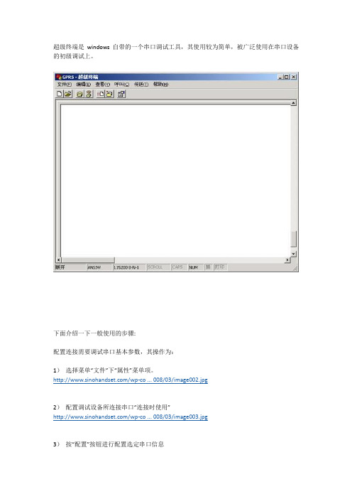
超级终端是windows自带的一个串口调试工具,其使用较为简单,被广泛使用在串口设备的初级调试上。
下面介绍一下一般使用的步骤:配置连接需要调试串口基本参数,其操作为:1)选择菜单“文件”下“属性”菜单项。
/wp-co ... 008/03/image002.jpg2)配置调试设备所连接串口“连接时使用”/wp-co ... 008/03/image003.jpg3)按“配置”按钮进行配置选定串口信息/wp-co ... 008/03/image004.jpg4)依次选定每秒位数(波特率)等参数,一般情况下MODEM设置波特率后即可,其它位取默认设置。
5)确定退出配置6)按工具条上“呼叫”按钮连接所调试设备/wp-co ... 008/03/image005.jpg7)输入英文字母AT然后回车,此时如果设置正确,则会返回英文字母OK/wp-co ... 008/03/image006.jpg8)如果参数设置不正确,则提示无法连接,或者连接后无法输入AT字母,此时,请确认步骤2)中串口选择正确、请确认波特率设置正确。
9)大部分GPRS MODEM出厂的时候其波特率已经设置为115200,但是也可能部分设置为9600或者其它。
在MODEM支持的范围内,越高的波特率代表了越高的计算机传输数据到MODEM的能力。
常用的几个AT命令1)AT测试指令,返回OK表示串口设备正常2)AT+CGMM显示MODEM型号3)AT+CGMR显示MODEM软件版本号4)AT+CGMI显示MODEM生产厂家5)AT+IPR=?/AT+IPR?/ AT+IPR=115200前者查询MODEM支持的所有波特率,后者显示当前设定波特率,最后一条是设置MODEM 波特率为115200。
串口升级操作步骤

通过串口连接升级操作步骤通过串口连接进行系统软件升级,即通过串口连接的方式登录设备,通过TFTP协议传输,进行的系统软件升级操作。
特别注意:1. 执行步骤6过程中如果升级u-boot不成功请保证设备持续运行,在此过程中不断电并且不重启,并请继续重新升级u-boot直到升级成功。
如果传输过程无法继续,可以使用Ctrl + c 退出升级,检查网络后请继续升级。
u-boot损坏会造成系统无法启动,需要回厂处理;2. 执行步骤6过程中,如果u-boot的版本是1.02(包括1.02)之前的版本,升级过程中会提示“Override Env parameters? (y/n)”,此时按N键,会保留环境变量和Mac地址,如果不慎按了Y键,环境变量和Mac地址会被恢复成初始值,需要重新设置设备的环境变量和Mac地址才能正常使用。
升级过程中失败的几种处理方式常见远程升级问题●上传文件时网络传输中断在上传升级文件到DC1001-FF的过程中,中断升级文件的传输,并在重传时间内无法恢复,则将导致此次升级失败并恢复到升级操作前状态。
常见通过串口连接升级问题●升级u-boot失败并已擦除原镜像如果FLASH已被擦除,则必须保持设备不断电不重启并立即重新升级u-boot,如果此时设备断电或重启将造成设备无法引导,需要回厂处理,使用JTAG重新升级u-boot 。
●升级uImage失败并已擦除原镜像升级uImage过程中失败则需要重新通过串口连接进行升级,否则无法启动设备。
●升级program失败并已擦除原镜像升级program过程中失败仍可启动系统,但需要重新通过串口连接进行升级或远程升级修复系统后才能恢复正常业务。
●升级config失败并已擦除原镜像升级config过程中失败仍可启动系统,但需要重新通过串口连接进行升级或远程升级修复系统后才能恢复正常业务。
DC1001-FF升级步骤升级u-boot 前请确保先断电重启,如果无法确保升级之前断电重启,请启动后在串口下进行如下设置:mw.b 0x04000008 0x01 此命令输入之后请确保1分钟之内系统没有自动重启再进行升级操作步骤如下:1、连接好串口和电口,给设备上电,通过串口连接进行如下操作。
单片机串口升级方法
单片机串口升级方法## Firmware Upgrade for Microcontroller Serial Interface (UART)。
### Overview.Firmware upgrades are crucial for enhancing the functionality, reliability, and security of embedded systems. The serial interface (UART) is a commonly used communication channel for firmware upgrades in microcontrollers. This article provides a comprehensive guide to firmware upgrades via UART, covering various techniques and best practices.### Methods for Firmware Upgrade through UART.There are several methods for upgrading firmware through UART:1. XMODEM Protocol: This protocol is widely used forreliable file transfer over serial connections. It utilizes error detection and retransmission mechanisms to ensure data integrity during transmission.2. YMODEM Protocol: This enhanced version of XMODEM offers faster transmission speeds and handles larger files more efficiently. It also supports batch file transfer and automatic file handling.3. Bootloader Method: This approach involves using a dedicated bootloader program stored in themicrocontroller's flash memory. The bootloader is responsible for receiving and programming the new firmware image into the microcontroller.4. UART Bootloader: This method leverages a bootloader that communicates directly over UART. It enables the transmission of firmware images without requiringadditional hardware or software.### Steps for Firmware Upgrade via UART.The general steps for firmware upgrade via UART are as follows:1. Prepare the Host Computer: Install the necessary software and drivers on the host computer to communicate with the microcontroller over UART.2. Configure the Microcontroller: Set up the microcontroller's UART settings (e.g., baud rate, parity) to match the host computer's configuration.3. Select the Firmware Upgrade Method: Choose the appropriate firmware upgrade method based on the microcontroller's capabilities and system requirements.4. Transfer Firmware Image: Use a terminal emulator or dedicated firmware upgrade software to transfer the firmware image to the microcontroller.5. Verify Firmware Update: After the transmission is complete, verify the firmware update by checking the microcontroller's operation or using checksums.6. Handle Errors: In case of errors during transmission or upgrade process, troubleshoot the issues and retry the firmware update.### Best Practices for Firmware Upgrades via UART.To ensure successful firmware upgrades via UART, follow these best practices:1. Use Error Detection Protocols: Employ error detection and correction mechanisms (e.g., XMODEM, checksums) to minimize data corruption during transmission.2. Test and Verify Firmware: Thoroughly test the new firmware image before deployment to avoid potential issues.3. Document Firmware Upgrades: Maintain detailed documentation of firmware upgrades, including the version, date, and any modifications made.4. Secure Firmware Updates: Implement robust securitymeasures to prevent unauthorized firmware updates and protect the system from malicious attacks.### 中文回答:## 单片机串口固件升级方法。
串口升级步骤

大华NVS串口升级步骤NVS IP地址和电脑IP地址需在同一网段。
设置TFTP文件夹路径“在查看---选项”,需注D系列和C系列不能搞错;设置迷你终端的串口“文件----系统设置----通讯设置”,端口和电脑的端口号一致,波特率为:115200。
设置好后点“建立连接”设置好TFTP和迷你终端后,开启NVS的同时,按三次“*”键Hit any key to stop autoboot: 1 0s3c2510 # setenv ipaddr 192.168.1.108 //IP地址为NVS地址s3c2510 # setenv serverip 192.168.1.100 //IP为电脑的地址s3c2510 # saveenv //保存Un-Protected 1 sectorsErasing sector 1 ...Saving environment to flash ...done.Protected 1 sectorss3c2510 # run da //清空存储器中数据Un-Protect Flash Bank # 1BootFile [armboot-x.bin.img], Load addr [0x100000]ARP broadcast 1eth addr: 00:1c:25:b6:53:0aGot good ARP - start TFTPServer ethernet address 00:1c:25:b6:53:0aTFTP from server 192.168.1.100; our IP address is 192.168.1.108Filename 'armboot-x.bin.img'.Load address: 0x100000Loading: ###################doneBytes transferred = 97230 (17bce hex)## Checking Image at 0x100000 ...Header CRC Checking ... OKImage Name: uClinuxImage Type: ARM Linux Firmware (gzip compressed)Data Size: 97166 Bytes = 94 kB = 0 MBLoad Address: 80000000Entry Point: 80020000Data CRC Checking ... OKErasing sector 0 ...Erasing sector 1 ...Erasing sector 2 ...Erasing sector 3 ...Erasing sector 4 ...Erasing sector 5 ...Erasing sector 6 ...Erasing sector 7 ...Erasing sector 8 ...done.Erased 9 sectors.Saving Image to Flash ...done.s3c2510 #Armboot version: 2.4.17 -- Mar 18 2008 //重启NVS Code range : 0x00000000 -> 0x0001c1a0DRAM Configuration:Bank #0: 00000000 64 MBFlash: 8 MB*** Using default environmentdo_saveenv ...Un-Protected 1 sectorsErasing sector 1 ...Saving environment to flash ...done.Protected 1 sectorscp15 register r1: 0xC000107DInstruction Cache is ONcp15 register r1: 0xC000107DData (writethrough) Cache is ONWrite Buffer Control register: 0x0000000CWrite Buffer is ONSerial: 000000000000000000HW ADDR0: 00:09:30:28:12:22DVRID: 0x0005Chan = 16; Product = 5; Func = 0; Ver = 0Alarm-mode: V2.0Hit any key to stop autoboot: 0s3c2510 # sensetenv ipaddr 192.168.1.108 //重新输入s3c2510 # setenv serverip 192.168.1.100 //重新输入s3c2510 # saveenv //保存Un-Protected 1 sectorsErasing sector 1 ...Saving environment to flash ...done.Protected 1 sectorss3c2510 # run up //升级BootFile [update.img], Load addr [0xa00000]ARP broadcast 1eth addr: 00:1c:25:b6:53:0aGot good ARP - start TFTPServer ethernet address 00:1c:25:b6:53:0aTFTP from server 192.168.1.100; our IP address is 192.168.1.108Filename 'update.img'.Load address: 0xa00000Loading:############################################################################### ############################################################################### ############################################################################### ############################################################################### ############################################################################### ############################################################################### ############################################################################### ############################################################################### ############################################################################### ############################################################################### ############################################################################### ############################################################################### ############################################################################### ############################################################################### ############################################################################### ############################################################################### ############################################################################### ######################################################################doneBytes transferred = 7233856 (6e6140 hex)## Checking Image at 0xa00040 ...Header CRC Checking ... OKImage Name: uClinuxImage Type: ARM Linux Standalone Program (gzip compressed)Data Size: 24576 Bytes = 24 kB = 0 MBLoad Address: 80020000Entry Point: 80030000Data CRC Checking ... OKPrograming start at: 0x80020000Erasing sector 9 ...done.Erased 1 sectors.Saving Image to Flash ...done.## Checking Image at 0xa06080 ...Header CRC Checking ... OKImage Name: uClinuxImage Type: ARM Linux Kernel Image (gzip compressed) Data Size: 6045696 Bytes = 5904 kB = 5 MBLoad Address: 80030000Entry Point: 80630000Data CRC Checking ... OKPrograming start at: 0x80030000Erasing sector 10 ...Erasing sector 11 ...Erasing sector 12 ...Erasing sector 13 ...Erasing sector 14 ...Erasing sector 15 ...Erasing sector 16 ...Erasing sector 17 ...Erasing sector 18 ...Erasing sector 19 ...Erasing sector 20 ...Erasing sector 21 ...Erasing sector 22 ...Erasing sector 23 ...Erasing sector 24 ...Erasing sector 25 ...Erasing sector 26 ...Erasing sector 27 ...Erasing sector 28 ...Erasing sector 29 ...Erasing sector 30 ...Erasing sector 31 ...Erasing sector 32 ...Erasing sector 33 ...Erasing sector 35 ... Erasing sector 36 ... Erasing sector 37 ... Erasing sector 38 ... Erasing sector 39 ... Erasing sector 40 ... Erasing sector 41 ... Erasing sector 42 ... Erasing sector 43 ... Erasing sector 44 ... Erasing sector 45 ... Erasing sector 46 ... Erasing sector 47 ... Erasing sector 48 ... Erasing sector 49 ... Erasing sector 50 ... Erasing sector 51 ... Erasing sector 52 ... Erasing sector 53 ... Erasing sector 54 ... Erasing sector 55 ... Erasing sector 56 ... Erasing sector 57 ... Erasing sector 58 ... Erasing sector 59 ... Erasing sector 60 ... Erasing sector 61 ... Erasing sector 62 ... Erasing sector 63 ... Erasing sector 64 ... Erasing sector 65 ... Erasing sector 66 ... Erasing sector 67 ... Erasing sector 68 ... Erasing sector 69 ... Erasing sector 70 ... Erasing sector 71 ... Erasing sector 72 ... Erasing sector 73 ... Erasing sector 74 ... Erasing sector 75 ... Erasing sector 76 ... Erasing sector 77 ...Erasing sector 79 ...Erasing sector 80 ...Erasing sector 81 ...Erasing sector 82 ...Erasing sector 83 ...Erasing sector 84 ...Erasing sector 85 ...Erasing sector 86 ...Erasing sector 87 ...Erasing sector 88 ...Erasing sector 89 ...Erasing sector 90 ...Erasing sector 91 ...Erasing sector 92 ...Erasing sector 93 ...Erasing sector 94 ...Erasing sector 95 ...Erasing sector 96 ...Erasing sector 97 ...Erasing sector 98 ...Erasing sector 99 ...Erasing sector 100 ...Erasing sector 101 ...Erasing sector 102 ...done.Erased 93 sectors.Saving Image to Flash ...done.## Checking Image at 0xfca0c0 ...Header CRC Checking ... OKImage Name: uClinuxImage Type: ARM Linux Standalone Program (gzip compressed) Data Size: 1159168 Bytes = 1132 kB = 1 MBLoad Address: 80630000Entry Point: 80780000Data CRC Checking ... OKPrograming start at: 0x80630000Erasing sector 106 ...Erasing sector 107 ...Erasing sector 108 ...Erasing sector 109 ...Erasing sector 110 ...Erasing sector 112 ...Erasing sector 113 ...Erasing sector 114 ...Erasing sector 115 ...Erasing sector 116 ...Erasing sector 117 ...Erasing sector 118 ...Erasing sector 119 ...Erasing sector 120 ...Erasing sector 121 ...Erasing sector 122 ...Erasing sector 123 ...done.Erased 18 sectors.Saving Image to Flash ...done.## Checking Image at 0x10e5100 ...Header CRC Checking ... OKImage Name: uClinuxImage Type: ARM Linux Standalone Program (gzip compressed)Data Size: 4096 Bytes = 4 kB = 0 MBLoad Address: 807c0000Entry Point: 80800000Data CRC Checking ... OKPrograming start at: 0x807c0000Erasing sector 131 ...done.Erased 1 sectors.Saving Image to Flash ...done. //升级成功s3c2510 # printenv //查看MAC地址bootcmd=fsload; go 40000bootdelay=1baudrate=115200icache="on"dcache="on"wbuffer="on"ethaddr=00:09:30:28:12:22netmask=255.255.0.0bootfile="image.cramfs.img"HW ADDR0=00:09:30:28:12:22 //该地址为升级后MAC地址,需和主板上的MAC地址一致,若不一致,按下步红色标记操作HW ADDR1=00:09:30:28:12:24dh_keyboard=1appauto=1reserved_mem_version=1da=protect off all; tftp 100000 armboot-x.bin.img; flwrite 80000000dc=tftp A00000 custom-x.cramfs.img; flwritedr=tftp A00000 romfs-x.cramfs.img; flwritedw=tftp A00000 web-x.cramfs.img; flwritedl=tftp A00000 logo-x.cramfs.img; flwritetk=tftp 40000 linux.bin; go 40000up=tftp A00000 update.img; flwriteclean=erase 1:9-134ID=000000000000000000filesize=6e6140ipaddr=192.168.1.108serverip=192.168.1.100Environment size: 682/8188 bytess3c2510 # setenv HWADDR 00:05:DA:00:39da:00:39:63 //设置机器主板上的MAC地址到NVS中s3c2510 # save //保存。
通过串口,修改开机LOGO
通过串口,修改开机LOGO步骤当没有SD卡,或者SD卡不可用时,可以临时通过串口来修改开机LOGO。
1. 把准备好的图片保存文件名为logo.bmp。
2. 把eWin系列产品上标有“SW1”的位置用跳线冒短接起来。
3. 打开DNW,配置串口波特率115200,串口号为电脑使用的串口“Configuration”-“options”配置串口波特率115200,串口号为计算机的串口号,连接串口出现以下信息4. 通过串口线把eWin产品的com1与计算机相连5. eWin产品上电,串口出现调试信息,当出现Initiating image launch in 2seconds信息时马上按空格键,出现以下信息0) USB DOWNLOAD image now(file:xip.bin)1) UART DOWNLOAD file now(file:eboot.nb0,logo.bmp,id.dat)2) Save logo.bmp to nand flash3) Save id.dat to nand flash4) Save eboot.nb0 to nand flash5) Update form SD card(file:eboot.nb0,id.dat,xip.bin,logo.bmp)6) LAUNCH existing Boot Media image6.选择1) UART DOWNLOAD file now(file:eboot.nb0,logo.bmp,id.dat),出现Now download file from UART...STATUS:7.打开dnw菜单Serial Port -> Transmit,选择文件logo.bmp8.下载结束后DNW上显示Download O.K.并重新进入主菜单,选择2) Save logo.bmp to nand flash,设备上显示Update logo.bmp OK!。
研发课堂丨iMXRT1052开发板在线升级操作方法
研发课堂丨iMXRT1052开发板在线升级操作方法飞凌 OK1052- C 开发板烧写方式及工具多种多样,现在我们先来总结一下:1、 SWD 方式烧写,使用 DAP 仿真器,上位机使用 keil MDK 点击 download 下载。
2、 USB 方式烧写,使用 USB 数据线连接板子和 PC 机,上位机有三个烧写工具:1)NXP MCU Boot Utility 工具。
2) RT-flash 工具。
3) MfgTool2工具。
3、 SD 方式卡烧写,将要烧写的镜像放入 SD 卡,从 SD 卡启动烧写程序进行烧写。
当然除了以上我们总结的几点,OK1052-C 还有其他烧写方式,这里不再一一列举。
这几种方式各有千秋也各有不便,具体优缺点需要根据大家的应用环境决定。
一、简单介绍一下 IAP今天给大家介绍一下,如何通过IAP 方式进行程序烧写。
目前OK1052-C IAP 功能,在设计在设计固件程序时编写两个项目代码,第一个项目程序( bootloder )不执行正常的功能操作,而只是通过UART 接收镜像数据,执行对第二部分代码的更新;第二个项目代码(app )才是真正的功能代码。
这两部分项目代码都同时烧录在User Flash 中,当芯片上电后,首先是第一个项目代码 bootloder 开始运行,它作如下操作:1)串口等待输入“ space ”键,等待超时时间 1000ms ;2)如果没有接收到“ space ”字符,则跳转到第二部分代码执行 app3)如果接收到该字符,进入选择菜单。
4)选择 2 执行更新操作5)选择镜像,并更新完成之后,再次进入菜单,可选择1 运行新的 app ,也可选择 3 重新启动系统:使用IAP 方式进行程序烧写,就省去了频繁使用仿真器连接烧写的麻烦,也不用像 USB 烧写那么繁琐。
不管是开发阶段还是维护阶段,都能轻松升级。
二、具体操作,实现 APP 升级OK1052-C IAP 主要使用串口通过 Ymodem 协议进行镜像数据传输,因为secureCRT 工具有Ymodem 传输功能,所以我们使用secureCRT 工具作为串口终端。
- 1、下载文档前请自行甄别文档内容的完整性,平台不提供额外的编辑、内容补充、找答案等附加服务。
- 2、"仅部分预览"的文档,不可在线预览部分如存在完整性等问题,可反馈申请退款(可完整预览的文档不适用该条件!)。
- 3、如文档侵犯您的权益,请联系客服反馈,我们会尽快为您处理(人工客服工作时间:9:00-18:30)。
串口更新image方法
1.设置TFTP服务器
1.1 在PC端打开tftp服务器
1.2 把image 文件放在tftp服务器设置的路径位置
或是把tftp服务器目录设置为image所在的文件夹,这样客户端就可以通过tftp协议下载服务器目录中的文件。
默认的,tftp服务器的目录为tftpd32.exe所在目录。
通过串口更新image,通常有两个文件
Kernel: vmlinux.lzma.uImage
Rootfs: ap99-2.6.31-jffs2
2.连接串口转接板到目标板上串口转接板排针线序:
7240/9342 排针线序
9342 排针线序(与7240/9342正好相反)
7240连接串口转接板
3.设置串口工具
打开串口工具,如超级终端,选择正确的COM口,配置为
●波特率115200
●数据为8
●奇偶校验无
●停止位 1
●数据流控制无
4.更新7240 image
4.1进入uboot
给目标板上电,此时串口工具会有大量的输出信息。
在串口输出到Hit any key to stop autoboot: 信息时,马上按回车或空格键
这样就进入到了uboot
4.2设置目标板IP地址和TFTP服务器地址
把目标板的网口连接到你的电脑上,或把目标板和你的电脑都连在同一个交换机上。
Tftp服务器的地址即你电脑的IP地址。
在uboot中输入以下命令设置目标板IP地址和tftp服务器地址
# setenv ipaddr [目标板ip地址如192.168.1.32]
# setenv serverip [你的tftp服务器的ip地址,即你PC的ip地址]
4.3 更新7240 kernel和rootfs命令
更新kernel:
# tftp 0x80060000 vmlinux.lzma.uImage && erase 0x9f660000 +0x120000 && cp.b 0x80060000
0x9f660000 0x120000
更新rootfs:
# tftp 0x80060000 ap99-2.6.31-jffs2 && erase 0x9f050000 +0x610000 && cp.b 0x80060000 0x9f050000 0x610000
更新过程如图所示:
4.4 擦除7240配置区域(可选)
网桥的配置参数保存在FLASH的固定区域,更新image并不会擦除这块区域,擦除了这块区域就相当于恢复了出厂设置。
# erase 0x9f780000 +0x70000
4.5 重启设备
# reset
4.6 进入系统
重启系统时还是会先进入到Uboot,这次不要按回车,等待几秒钟后会自动启动系统,在串口输出到login提示登录时,
输入用户名root,password为5up
5.更新其他方案image命令
注意进入uboot后设置tftp服务器的ip地址
5.1 9342_f2e
9342_f2e方案包括的设备有9342_5C, 9342_2C, 9342_3380 命令:
# set bc mi124_f2e && run lk && run lf
5.2 9344_s27
9344_s27方案包括的设备有9344_5E
# run lk && run lf。
