Ultrasonic weld properties of heterogeneous polymers Polylactide and poly
冶金专业英语词汇(U-Z)
unit cell 单位晶胞
unit cell vector 点阵矢
unit dislocation 单位位错
unit load 单位负载
unit metal consumption 金属单位消耗
unit power 动力单位
unitary system 一元系
vacuum arc remelting 真空电弧重熔
vacuum arc remelting process 真空电弧重熔法
vacuum carbonitriding 真空碳氮化
vacuum casting 真空铸造
vacuum chamber 真空室
vacuum converter 真空转炉
v notch v 形缺口
vacancy 空位
vacancy cluster 空位团
vacancy condensation 空位凝聚
vacancy diffusion 空位扩散
vacancy loop 空位环
vacancy ring 空位环
vacancy source 空位源
vacuometer 真空计
unitemper mill 双二辊式平整机
universal beam mill 万能式钢梁轧机
universal coiler 通用卷取机
universal coupling 万向联轴节
universal indicator 通用指示剂
universal mill 万能轧机
universal plate 齐边中厚板
ullmannite 锑硫镍矿
螺母与螺栓凸焊(翻译)

I. GENERAL 概述………………………………………………………………..………..Scope of Engineering Specification, General Statement ………….……….….总体说明,本规范适用范围Process Description ……………………………………………….………..…….焊接过程描述Design Guidelines 设计准则……………………………………………………………..….Size Relative to Base Sheet Metal Thickness 紧固件对板材厚度的相对尺寸 Size in Base Sheet Metal 板材上孔的尺寸Strength 紧固件强度of Base Sheet Metal 板材的平面度of Fastener 紧固件的位置Applicable Materials 适用材料………………………………………………………Joint Identification Symbols 焊接接头识……………………………………………………II. SUMMARY OF PRODUCTION VALIDATION AND IN-PROCESS TESTS ……..生产验证及过程测试总述III. TEST PROCEDURES AND REQUIREMENTS ………………………………试验过程及要求Applicability of Test Procedures for PV- and IP-Test Phases …………………. PV试验阶段及IP试验阶段的适用性Weld Parameter Monitoring 焊接参数监控……………………..…...………………… Introduction 简介Welding Current over Time [A] 焊接电流Electrode Force [N] 电极力Dimensional and Visual Inspection of the Welded Fastener ……………………被焊紧固件的尺寸校核及目视检查Introduction 简介Gap between Fastener and Base Sheet Metal 紧固件与板材的间隙Burn Through into Base Sheet Metal 板材的烧穿Deformation of Fastener Body 紧固件的变形Cracks 破裂Flash on Threads 螺纹上的毛刺Metal spatter 金属飞溅Position of Nut on Component 螺母在部件中的位置Perpendicularity of Bolt 螺栓的垂直度Inspection of Section Cuts 剖面切割检查……………………………………………Introduction 简介Gap between Fastener and Base Sheet Metal 紧固件与板材之间的间隙Penetration into Base Sheet Metal 板材的焊透率Porosity 气孔Cracks 破裂Inclusions 夹杂Hardness 硬度Destructive, Non-Destructive, and Functional Testing ………………………….有损检测,无损检测及功能检测Introduction 简介Static Tensile Test 静态拉伸试验Torque Test 扭矩试验III.5.3.1 Torque Test (Destructive) 扭矩试验(有损)III.5.3.2 Torque Test (Non-Destructive) 扭矩试验(无损)Push Out / Pull Out Test (Destructive)推出/剥落试验(有损)Hammer/Chisel Test 榔头/凿子试验Thread Test 螺纹测试Leakage Test 密封性试验Durability / Fatigue Test 寿命/疲劳测试Permissible Repair Methods ……………………………………………...…...…允许的返修方法IV. REVALIDATION REQ UIREMENTS ……………………………………再验证要求V. INSTRUCTIONS AND NOTES …………………………………………说明及注意事项VI. COMPILATION OF RE FERENCE DOCUMENTS ……………………参考文件I. GENERAL 综述Scope of Engineering Specification, General Statement 总体说明,本规范适用范围This Engineering Specification is issued to define design factors and performance requirements applicable to the joining of nuts and bolts using the projection welding process. It covers manual and automated projection welding on sheet steel having a minimum of 0.5 mm and a maximum of 3.0 mm thickness. It covers metric dimensions up to M16 and property class and fasteners, but not fasteners of the property class .本规范用于规定螺母及螺栓凸焊的设计要素和焊接过程要求,它涉及厚度从~3.0mm的钢板的手工凸焊和自动凸焊。
超声波技术在肉品加工中的应用研究进展

黄荣秋,臧明伍,李海花,等. 超声波技术在肉品加工中的应用研究进展[J]. 食品工业科技,2023,44(20):431−439. doi:10.13386/j.issn1002-0306.2022100228HUANG Rongqiu, ZANG Mingwu, LI Haihua, et al. Research Advance of Application of Ultrasonic Treatment in Meat Processing[J].Science and Technology of Food Industry, 2023, 44(20): 431−439. (in Chinese with English abstract). doi: 10.13386/j.issn1002-0306.2022100228· 专题综述 ·超声波技术在肉品加工中的应用研究进展黄荣秋1,2,臧明伍1, *,李海花2,柴 悦1,2,赵 冰1,张顺亮1,张哲奇1,张凯华1,李 素1,吴倩蓉1,李 丹1(1.中国肉类食品综合研究中心北京食品科学研究院,北京 100068;2.天津农学院动物科学与动物医学院天津市农业动物繁育与健康养殖重点实验室,天津 300384)摘 要:目前,超声波处理在肉品加工前处理及热加工中得到广泛的研究和应用,研究普遍认为超声波的空化效应、机械效应和热效应是引起肉品品质改变的主要原因。
本文综述了超声波技术在肉品加工中的技术原理及其在肉品加工前处理和热加工过程中的应用进展,阐述了超声波辅助加工过程中对肉类嫩度、色泽、保水性及脂质、蛋白质氧化的改善效果,并对其应用前景进行展望。
总体而言,超声波技术在辅助冻结、解冻、腌制、热加工中对肉类理化性质及感官品质具有显著改善作用。
本文为超声波技术在肉品加工中的应用提供了理论参考。
关键词:超声波,原理,应用,前处理,热加工,肉类品质本文网刊:中图分类号:TS251.4 文献标识码:A 文章编号:1002−0306(2023)20−0431−09DOI: 10.13386/j.issn1002-0306.2022100228Research Advance of Application of Ultrasonic Treatment in MeatProcessingHUANG Rongqiu 1,2,ZANG Mingwu 1, *,LI Haihua 2,CHAI Yue 1,2,ZHAO Bing 1,ZHANG Shunliang 1,ZHANG Zheqi 1,ZHANG Kaihua 1,LI Su 1,WU Qianrong 1,LI Dan 1(1.China Meat Research Center, Beijing Academy of Food Science Center for Food Evaluation, Beijing 100068, China ;2.Tianjin Key Laboratory of Agricultural Animal Breeding and Healthy Husbandry, College of Animal Science andVeterinary Medicine, Tianjin Agricultural University, Tianjin 300384, China )Abstract :Ultrasonic treatment has been widely researched and applied in the pre-processing and thermal processing of meat and meat processed products at present. The cavitation effect, mechanical effect, and thermal effect of ultrasonic wave are considered to be the main reasons for the changes of meat quality. In this paper, the basic principle of ultrasound and the application progress in pre-treatment and thermal processing in meat processing are reviewed. The effects of ultrasonic treatment on meat tenderness, color, water holding capacity, and lipid and protein oxidation are summarized. The future prospect of its application is also proposed. In general, the physicochemical property and sensory quality of meat and meat processed products are significantly improved during ultrasound-assisted freezing, thawing, curing, and thermal processing.The paper provides a theoretical reference for the application of ultrasonic treatment in meat processing.Key words :ultrasonic wave ;principle ;application ;pre-treatment ;thermal processing ;meat quality超声波是由声波传播过程中介质分子运动产生的机械波组成,传播频率高,不能被人耳察觉[1],广泛应用于化工、医药、农业等领域[2−5]。
超声波对石英晶体微天平响应性能的影响

0引言超声波是指频率在20kHz~106Hz 的机械波,是一种波动形式,又是一种能量形式。
超声波在空气中衰减较快,而在固体、液体中的衰减却很小,由于频率高、波长短,具有方向性好、功率大、穿透力强的特点,在传播过程中与媒介相互作用产生超声效应。
超声波与媒介的相互作用可分为机械作用、空化作用和热作用。
近年来,随着超声波技术的日益发展与成熟,其在新材料合成、化学反应、传递过程的强化以及废水处理等领域得到了广泛的应用[1~3]。
此外,超声清洗也是常见的清洗方法,其原理是利用超声波在清洗液中疏密相间的向前辐射,使液体流动而产生数以万计的微小气泡,存在于液体中的微小气泡在声场的作用下振动,当声压达到一定值时,气泡迅超声波对石英晶体微天平响应性能的影响盛睿,庄建梅,李栋栋,刘金枝,申大忠*(山东师范大学化学化工与材料科学学院,山东济南250014)摘要:该文以阻抗分析法研究了超声波对石英晶体微天平(QCM)响应特性的影响,结果表明,在超声波存在时QCM 的纵波传播与反射受到干扰,QCM 的阻抗-频率曲线上出现很多的毛刺干扰波,使QCM 的信噪比下降。
当采取消除纵波干扰的措施后,毛刺干扰波消失,实验测试了QCM 的谐振频率及动态电阻对表面质量负载变化及液体粘度、密度改变的响应,证实超声波对QCM 的厚度剪切模式无影响。
QCM 应用于监测表面活性剂去除油污膜的过程,结果表明在超声波作用下油污膜的去除速率大幅度提高。
关键词:石英晶体微天平;阻抗分析;超声波;油污去除Influence of ultrasonic wave on the response of a quartz crystalmicrobalance in impedance analysis methodSheng Rui,Zhuang Jian -mei,Li Dong -dong,Liu Jin -zhi,Shen Da -zhong *(School of Chemistry ,Chemical Engineering and Material Science ,Shandong Normal University ,Jinan 250014,China )Abstract:The effect of ultrasonic wave on the response of a quartz crystal microbalance (QCM)was investigated by an impedance analysis method.In the presence of ultrasonic wave,the signal-to-noise of QCM in a liquid phase is reduced as burrs are added on its impedance-frequency spectrum.This kind of effect is ascribed to the fact that the reflection condition for the longitudinal wave from QCM is disturbed by ultrasonic wave.The burr noise on the resonant peak of QCM disappears when the longitudinal wave effect is eliminated.The changes in the resonant frequency and motional resistance of QCM were measured under different viscosity and density of liquid phase and the surface mass loading.It is shown that the thickness-shear model of QCM is not influenced by ultrasonic wave effect.The removal of hydrophobic film by non-ionic surfactant were monitored by QCM.The removal is greatly speeded under ultrasonic conditions.Key words:quartz crystal microbalance ;impedance analysis ;ultrasonic wave ;hydrophobic film removal基金项目:国家自然科学基金资助项目(No.20775045)和化学生物传感与计量学国家重点实验室开放课题(No.2008012)*通讯联系人,E-mail :dzshen@Vol.29,No.4D ec .2009化学传感器CHEMICALSENSORS第29卷第4期2009年12月速增长,然后突然闭合,在气泡闭合时产生冲击波,在其周围产生上千个大气压的压力,破坏不溶性污物而使它们分散乳化于清洗液中,从而达到清洗件表面净化的目的。
超声波无损探伤技术中文翻译稿模板
Nondestructive MaterialT esting withUltraso ni c s 使用超声波对材料进行的非破坏性检测Introduction to the Basic Principles基本原理介绍UNION ELECTRIC STEEL CORPORATION美国联合电钢( 戴维) 轧辊公司安多利国际有限公司翻译3月06日Contents 内容安多利国际有限公司Introduction介绍 . . . . . . . . . . . . . . . . . . . . . . . . . . . . . . . . . . . . . . . . . . . .41.Why use ultrasonics for nondestructive material testing?为什么使用超声波进行非破坏性材料检测? . . . . . . . . . . .52.Ultrasonic testing tasks 超声波检测任务 . . . . . . . . . . . . . . . . . . . . . . .53.Detection of discontinuities 不连续的发现 . . . . . . . . . . . . . . . . . . . . . .64.Method of testing and instrument technology 检测方法和仪器技术. . .104.1The ultrasonic flaw detector 超声波裂纹检测仪 . . . . . . . . . . . . . . . . . . . .104.2Near r esolution . 近场的处理 . . . . . . . . . . . . . . . . . . . . . . . . . . . . . . . . . .154.3The pr obe 探头. . . . . . . . . . . . . . . . . . . . . . . . . . . . . . . . . .. . . . . . . . . . .164.4Refraction and mode conversion 折射和模式的转变. . . . . . . .174.5Characteristics of angle-beam probes角度探头的特性. . . . . . . . . . . . . . . . . .194.6The TR pr obe TR探头 . . . . . . . . . . . . . . . . . . . . . . . . . . . . . . . . . . . . . . . . .205.Locating discontinuities 断裂的定位. . . . . . . . . . . . . . . . . . . . . . . . . . 225.1Calibration of the instrument 仪器校准 . . . . . . . . . . . . . . . . . . . . . . .225.1.1Calibration with a straight-beam probe平行光束探头的校准 . . . . . . . . . . . . . . . . . . .225.1.2Calibration with a TR pr obe TR探头的校准 . . . . . . . . . . . . . . . .. . . . . . . .245.1.3Calibration with an angel-beam probe 角度探头的校准 . . . .. . . . . . . .. . .265.1.4Locating reflectors with an angle-beam probe 使用角度探头对反射器进行定位 . .286.Evaluation of discontinuities 断裂的评估 .. . . . . . . . . . . . . . . . . . . . . .296.1Scanning method 扫描方法 . . . . . . . . . . . . . . . . . . . . . . . . . . . . . . . . . . .296.2Evaluation of small discontinuities: The DGS method对小断裂的评估: DGS方法. . . . .306.3Sound attenuation 消音. . . . . . . . . . . . . . . . . . . . . . . . . . . . . . . . . . . . . .346.4The refer ence block method 叁考程序块方法. . . . . . . . . . . . . . . . . . . . . .346.4.1Comparison of echo amplitudes 回声振幅的比较 . . . . . . . . . . . . . . . . . . . .346.4.2Distance amplitude curve 振幅曲线的距离. . . . . . . . . . . . . . . . . . . . . . . . ..357.Documentation 文件. . . . . . . . . . . . . . . . . . . . . . . . . . . . . . . . . . . . . . .378.Diagnosis of indications (outlook)指示的分析诊断. . . . . . . . . . . . . . . . . . . . . .40Refer ence list 参考清单. . . . . . . . . . . . . . . . . . . . . . . . . . . . . . . . . . . . . . . . . .41前言因时间仓促, 加之专业技术欠缺, 本译文一定会有很多不准确的地方。
美标超声波无损探伤UTII级考试习题翻译
4.1 The size of a penetrant indication depends on:渗透剂的显示大小取决于:A.the size of the discontinuity. 不连续的大小B.the discontinuity entrapment efficiency.C.the technique of penetrant testing. 渗透检测技术D.all of the above. 上面全部E.only a and c above. 只有上面的a和b4.2 The most sensitive application technique for dry developer is:对干燥显像剂最为敏感的应用技术是:A.Immersion. 浸入B.a dust cloud. 粉尘云C.A fluidized bed. 流化床D.A dust cloud —electrostatic gun. 粉尘云—静电抢4.3 one advantage of having a little background fluorescence is that it:小背景荧光的一个优点是它:A.reduces the contrast of the indication. 减少现象的对比度B.Indicates that the part was not overwashed. 显示不被清洗的部分C.Reveals an excessive emulsification time. 显示过度乳化时间D.Is hard to remove when a highly sensitive penetrant is applied to rough or porous surfaces.很难去除用在粗糙或多孔表面的高灵敏度渗透剂4.4 the water wash test is used to evaluate the washing properties of penetrant and emulsifiers. The spray nozzle is held 30 cm(12 in.) from the wash surface. The water pressure must not exceed:水洗涤实验用于评估渗透剂和乳化剂的洗涤性能。
超声波焊接 ultrasonic welding

超声波焊接ultrasonic welding
热塑性塑料在超声波振动作用下,由于表面分子间摩擦生热而使两块塑料熔接在一起的焊接方法。
超声波金属焊接
超声波金属焊接是利用高频振动波传递到两个需焊接的金属表面,在加压的情况下,使两个金属表面相互摩擦而形成分子层之间的熔合,其优点在于快速、节能、熔合强度高、导电性好、无火花、接近冷态加工;缺点是所焊接金属件不能太厚(一般小于或等于5mm)、焊点位不能太大、需要加压。
超声波金属焊接是一种机械处理过程,在焊接过程中,并无电流在被焊件中流过,也无诸如电焊模式的焊弧产生,由于超声焊接不存在热传导与电阻率等问题,因此对于有色金属材料来说,无疑是一种理想的金属焊接设备系统,对于不同厚度的片材,能有效地进行焊接。
焊接优点:
1)、焊接材料不熔融,不脆弱金属特性。
2)、焊接后导电性好,电阻系数极低或近乎零。
3)、对焊接金属表面要求低,氧化或电镀均可焊接。
4)、焊接时间短,不需任何助焊剂、气体、焊料。
5)、焊接无火花,环保安全。
超声波金属焊接适用产品:
1)、镍氢电池镍氢电池镍网与镍片互熔与镍片互熔。
2)、锂电池、聚合物电池铜箔与镍片互熔,铝箔与铝片互熔。
3)、电线互熔,偏结成一条与多条互熔。
4)、电线与名种电子元件、接点、连接器互熔。
5)、名种家电用品、汽车用品的大型散热座、热交换鳍片、蜂巢心的互熔。
6)、
电磁开关、无熔丝开关等大电流接点,异种金属片的互熔。
7)、金属管的封尾、切断可水、气密。
211091445_牡丹籽粕蛋白提取工艺优化和功能性质分析
李若敏,张焕新,盘赛昆,等. 牡丹籽粕蛋白提取工艺优化和功能性质分析[J]. 食品工业科技,2023,44(8):197−204. doi:10.13386/j.issn1002-0306.2022050251LI Ruomin, ZHANG Huanxin, PAN Saikun, et al. Process Optimization and Functional Properties of Peony Seeds Protein[J]. Science and Technology of Food Industry, 2023, 44(8): 197−204. (in Chinese with English abstract). doi: 10.13386/j.issn1002-0306.2022050251· 工艺技术 ·牡丹籽粕蛋白提取工艺优化和功能性质分析李若敏1,2,张焕新1, *,盘赛昆2,叶静静1(1.江苏农牧科技职业学院,江苏泰州 225300;2.江苏海洋大学食品科学与工程学院,江苏连云港 222005)摘 要:以酶水解-超声辅助碱溶酸沉法提取蛋白工艺为基础,初步对牡丹籽中粗蛋白进行分离提取。
通过单因素实验和响应面试验,考察料液比、超声温度、酶用剂量、超声时间四个因素对牡丹籽粕蛋白提取率的影响,确定最佳提取工艺,并测定其功能特性。
结果表明,酶水解-超声辅助碱溶酸沉法提取牡丹籽粕蛋白最优工艺条件为:料液比为1:9.8(w/v ),超声温度为49.5 ℃,酶用剂量为1.9%,超声时间为119 min 。
在此条件下,蛋白质提取率达到90.95%。
此时所得蛋白与常规法提取蛋白相比,氨基酸种类齐全、必需氨基酸含量均有所提高,功能特性如持水性、吸油性、乳化性皆优于常规法提取蛋白的功能特性,且乳化的稳定性更优,由此推测可作为食品加工乳化剂。
因此酶水解-超声辅助碱溶酸沉法提取的牡丹籽粕蛋白具有更高的营养价值和更好的功能特性。
ultrosonic welding

Ultrasonic weldingUltrasonic welding is an industrial technique whereby high-frequency ultrasonic acoustic vibrations are locally applied to workpieces being held together under pressure to create a solid-state weld. It is commonly used for plastics, and especially for joining dissimilar materials. In ultrasonic welding, there are no connective bolts, nails, soldering materials, or adhesives necessary to bind the materials together.HistoryIn 1960 Sonobond Ultrasonic, originally known as Aeroproject, developed the first metal ultrasonic welding machine to be awarded an United States Patent. ProcessFor joining complex injection molded thermoplastic parts, ultrasonic welding equipment can be easily customized to fit the exact specifications of the parts being welded. The parts are sandwiched between a fixed shaped nest (anvil) and a sonotrode (horn) connected to a transducer, and a ~20 kHz low-amplitude acoustic vibration is emitted. (Note: Common frequencies used in ultrasonic welding of thermoplastics are 15 kHz, 20 kHz, 30 kHz, 35 kHz, 40 kHz and 70 kHz). When welding plastics, the interface of the two parts is specially designed to concentrate the melting process. One of the materials usually has traditionally a spiked energy director which contacts the second plastic part. The ultrasonic energy melts the point contact between the parts, creating a joint. This process is a good automated alternative to glue, screws or snap-fit designs. It is typically used with small parts (e.g. cell phones, consumer electronics, disposable medical tools, toys, etc) but itcan be used on parts as large as a small automotive instrument cluster. Ultrasonic can also be used to weld metals, but are typically limited to small welds of thin, malleable metals, e.g. aluminum, copper, nickel. Ultrasonic would not be used in welding the chassis of an automobile or in welding pieces of a bicycle together, because of the power levels required.Ultrasonic welding of thermoplastics causes local melting of the plastic due to absorption of vibration energy. The vibrations are introduced across the joint to be welded. In metals Ultrasonic welding occurs due to high-pressure dispersion of surface oxides and local motion of the materials. Although there is heating, it is not enough to melt the base materials. Vibrations are introduced along the joint being welded.Practical application of ultrasonic welding for rigid plastics was completed in the 1960s. At this point only hard plastics could be welded. The patent for the ultrasonic method for welding rigid thermoplastic parts was awarded to Robert Soloff and Seymour Linsley in 1965. Soloff, the founder of Sonics & Materials Inc., was a lab manager at Branson Instruments where thin plastic films were welded into bags and tubes using ultrasonic probes. He unintentionally moved the probe close to a plastic tape dispenser and the halves of the dispenser welded together. He realized that the probe did not need to be manually moved around the part but that the ultrasonic energy could travel through and around rigid plastics and weld an entire joint. He went on to develop the first ultrasonic press. The first application of this new technology was in the toy industry.The first car made entirely out of plastic was assembled using ultrasonic welding in 1969. Even though plastic cars did not catch on ultrasonic welding did. The automotive industry has used it regularly since the 1980s. It is now used for a multitude of applications.Ultrasonic welding can be used for both hard and soft plastics, such as semicrystalline plastics, and metals. Ultrasonic welding machines also have much more power now. The understanding of ultrasonic welding has increased with research and testing. The invention of more sophisticated and inexpensive equipment and increased demand for plastic and electronic components has led to a growing knowledge of the fundamental process. However, many aspects of ultrasonic welding still require more study, such as relating weld quality to process parameters. Ultrasonic welding continues to be a rapidly developing field. Benefits of Ultrasonic welding that it is much faster than conventional adhesives or solvents. Drying time is very quick, the pieces do not need to remain in a jig for long periods of time waiting for the joint to dry or cure. The welding can easily be automated also, making clean and precise joints. Site of the weld does also very clean not need any touch up to material and bond.ComponentsAll ultrasonic welding systems are composed of the same basic elements:∙ A press to put the 2 parts to be assembled under pressure∙ A nest or anvil where the parts are placed and allowing the high frequency vibration to be directed to the interfaces∙An ultrasonic stack composed of a converter or piezoelectric transducer, an optional booster and a sonotrode (US: Horn). All three elements of the stack are specifically tuned to resonate at the same exact ultrasonic frequency(Typically 20, 30, 35 or 40 kHz)o Converter: Converts the electrical signal into a mechanical vibrationo Booster: Modifies the amplitude of the vibration. It is also used in standard systems to clamp the stack in the press.o Sonotrode: Applies the mechanical vibration to the parts to be welded.∙An electronic ultrasonic generator (US: Power supply) delivering a high power AC signal with frequency matching the resonance frequency of thestack.∙ A controller controlling the movement of the press and the delivery of the ultrasonic energy.ApplicationsThe applications of ultrasonic welding are extensive and are found in many industries including electrical and computer, automotive and aerospace, medical, and packaging. Whether two items can be ultrasonically welded is determined by their thickness. If they are too thick this process will not join them. This is the main obstacle in the welding of metals. However, wires, microcircuit connections, sheet metal, foils, ribbons and meshes are often joined using ultrasonic welding. Ultrasonic welding is a very popular technique for bonding thermoplastics. It is fast and easily automated with weld times often below one second and there is no ventilation system required to remove heat or exhaust. This type of welding isoften used to build assemblies that are too small, too complex, or too delicate for more common welding techniques.Computer & electrical industriesIn the electrical and computer industry ultrasonic welding is often used to join wired connections and to create connections in small, delicate circuits. Junctions of wire harnesses are often joined using ultrasonic welding. Wire harnesses are large groupings of wires used to distribute electrical signals and power. Electric motors, field coils, transformers and capacitors may also be assembled with ultrasonic welding. It is also often preferred in the assembly of storage media such as flash drives and computer disks because of the high volumes required. Ultrasonic welding of computer disks has been found to have cycle times of less than 300 ms. One of the areas in which ultrasonic welding is most used and where new research and experimentation is centered is microcircuits. This process is ideal for microcircuits since it creates reliable bonds without introducing impurities or thermal distortion into components. Semiconductor devices, transistors and diodes are often connected by thin aluminum and gold wires using ultrasonic welding. It is also used for bonding wiring and ribbons as well as entire chips to microcircuits. An example of where microcircuits are used is in medical sensors used to monitor the human heart in bypass patients.One difference between ultrasonic welding and traditional welding is the ability of ultrasonic welding to join dissimilar materials. The assembly of battery components is a good example of where this ability is utilized. When creating battery and fuel cell components, thin gauge copper, nickel and aluminumconnections, foil layers and metal meshes are often ultrasonically welded together. Multiple layers of foil or mesh can often be applied in a single weld eliminating steps and cost.Aerospace & automotive industriesFor automobiles, ultrasonic welding tends to be utilized in the assembly of large plastic components and electrical components such as instrument panels, door panels, lamps, air ducts, steering wheels, and upholstery and engine components. As plastics have continued to replace other materials in the design and manufacture of automobiles, the assembly and joining of plastic components has increasingly become a critical issue. Some of the advantages for ultrasonic welding are low cycle times, automation, low capital costs, and flexibility. Also, ultrasonic welding does not damage surface finish, which is a crucial consideration for many car manufacturers, because the high-frequency vibrations prevent marks from being generated.Ultrasonic welding is generally utilized in the aerospace industry when joining thin sheet gauge metals and other lightweight materials. Aluminum is a difficult metal to weld using traditional techniques because of its high thermal conductivity. However, it is one of the easier materials to weld using ultrasonic welding because it is a softer alloy metal and thus a solid-state weld is simple to achieve. Since aluminum is so widely used in the aerospace industry, it follows that ultrasonic welding is an important manufacturing process. Also, with the advent of new composite materials, ultrasonic welding is becoming even more prevalent. It has been used in the bonding of the popular composite material carbon fiber.Numerous studies have been done to find the optimum parameters that will produce quality welds for this material.Medical industryIn the medical industry ultrasonic welding is often used because it does not introduce contaminants or degradation into the weld and the machines can be specialized for use in clean rooms. The process can also be highly automated, provides strict control over dimensional tolerances and does not interfere with the biocompatibility of parts. Therefore, it increases part quality and decreases production costs. Items such as arterial filters, anesthesia filters, blood filters, IV catheters, dialysis tubes, pipettes, cardiometry reservoirs, blood/gas filters, face masks and IV spike/filters can all be made using ultrasonic welding. Another important application in the medical industry for ultrasonic welding is textiles. Items like hospital gowns, sterile garments, masks, transdermal patches and textiles for clean rooms can be sealed and sewn using ultrasonic welding. This prevents contamination and dust production and reduces the risk of infection.Packaging industryPackaging is perhaps the application in which ultrasonic welding is most often used. Incredibly wide arrays of everyday items are either created or packaged using ultrasonic welding techniques. Sealing containers, tubes and blister packs are some common applications.Ultrasonic welding has also found application in the packaging of dangerous materials such as explosives, fireworks and other reactive chemicals. These itemstend to require hermetic sealing but cannot be subjected to high temperatures. One simple example of this application is the container for butane lighter. This container weld must be able to withstand high pressure and stress and must be airtight to contain the butane. Another example is the packaging of ammunition and propellants. Again, these packages must be able to withstand high pressure and stresses in order to protect the consumer from the contents when sealing hazardous materials safety is a primary concern. Thus, the reliability and automation of this process are strong benefits for companies.The food industry finds ultrasonic welding preferable to traditional joining techniques because it is fast, sanitary and can produce hermetic seals. Milk and juice containers are examples of some products that are often sealed using ultrasonic welding. The paper parts to be sealed are coated with plastic, generally polypropylene or polyethylene, and then welded together to create an airtight seal. The main obstacle to overcome in this process is the setting of the parameters. For example, if over-welding occurs then the concentration of plastic in the weld zone may be too low and cause the seal to break. If it is under-welded the seal is incomplete. Also, variations in the thicknesses of materials can cause variations in weld quality. Therefore, the preparation of materials to be welded is extremely important. Some other food items that are sealed using ultrasonic welding include candy bar wrappers, frozen food packages and beverage containers.In summary, the electrical and computer, automotive, aerospace, medical, and packaging industries are some of the many industries in which ultrasonic welding is utilized. This process is used to assemble everything from microcircuits to milkcartons. It is increasing in popularity throughout many of these industries because of low cycle times, automation, low capital costs, flexibility, cleanliness, dimensional reliability and the bonding of dissimilar materials. Some of the drawbacks of ultrasonic welding are that its use is limited by the thickness of the materials, it may require expensive specialized tooling and it may generate noise. As these drawbacks are overcome by continually developing technologies, it will be interesting to see how this unique welding technique continues to be utilized. SafetyUltrasonic welding machines, like most industrial equipment, pose the risk of some hazards. These include exposure to high heat levels and voltages. This equipment should always be operated using the safety guidelines provided by the manufacturer in order to avoid injury. For instance, operators must never place hands or arms near the welding tip when the machine is activated. Also, operators should be provided with hearing protection and safety glasses. Operators should be informed of the OSHA regulations for the ultrasonic welding equipment and these regulations should be enforced.Ultrasonic welding machines must receive routine maintenance and inspection. Panel doors, housing covers and protective guards may need to be removed for maintenance. This should be done when the power to the equipment is off and only by the trained professional who is servicing the machine.Since this is an ultrasonic process it would seem that sound would not be an issue. However, sub-harmonic vibrations, which can create annoying audible noise, maybe caused in larger parts near the machine due to the ultrasonic welding frequency. This noise can be dampened by clamping these large parts at one or more locations. Also, high-powered welders with frequencies of 15 kHz and 20 kHz typically emit a potentially damaging high-pitched squeal in the range of human hearing. Shielding this radiating sound can be done using an acoustic enclosure. In short, there are hearing and safety concerns with ultrasonic welding that are important to consider, but generally they are comparable to those of other welding techniques.。
翻译——精选推荐

Modelling the grain orientation of austenitic stainless steel multipass welds to improve ultrasonic assessment of structural integrity奥氏体不锈钢的多路模拟晶粒取向改善焊缝超声评价结构完整性J. Moysan a,*, A. Apfel a, G. Corneloup a, B. Chassignole bJ.莫伊桑A.阿普费尔G.科尔内卢帕 B.沙西尼奥尔aLaboratoire de Caracte´risation Non Destructive (LCND, EA 3153), Universite´ de la Me´diterrane´e, IUT Avenue Gaston Berger,13625 Aix-en-Provence Cedex, FrancebElectricite´ De France, Direction Etudes et Recherches, Les Renardie`res, 77818 MoretsurLoing, FranceReceived 1 August 2002; revised 4 February 2003; accepted 4 February 2003 AbstractKnowledge of the grain orientation quantifies the material anisotropy which helps to ensure the good ultrasonic testing of weldedassemblies and the assessment of their mechanical integrity. The model described here concerns the weld solidification of 316L stainlesssteel. The solidification of multipass welds made with a shielded electrode raises many unsolved modelling questions as it involves heat andfluid flow modelling in addition to soluteredistribution models. To overcome these difficulties we have developed the MINA model topredict the resulting grain orientations without using a complete solidification model. This model relies upon a phenomenologicaldescriptionof grain orientations from macrograph analysis. One important advance of this model is to include data reporting in the welding notebook thatensures the generality of the model. This model allows us to accurately simulate the ultrasonic testing of welded co mponents and to propose anew tool to associate welding design with the ultrasonic assessment of structural integrity.Keywords: Welding; Anisotropy; Modelling; Ultrasound; Structural integrity文摘晶粒取向量化材料各向异性的知识,有助于确保良好的焊接程序集和评估超声检测机械的完整性。
恒逸成功首创无锑环保聚酯产品

57王璐,等:超声波焊接条件对PC/ABS与PMMA焊接强度的影响(3)在PC/ABS合金中,降低PC含量可以提高PC/ABS合金与PMMA焊接强度。
(4)采用高分子量的PC,可以改善传递能量的效率,会使PC/ABS合金与PMMA焊接强度提高。
参考文献[1] 张胜玉.塑料超声波焊接技术[C]∥2014年中国工程塑料复合材料技术研讨会议论文集,济南:工程塑料应用杂志社,2014.Zhang Shengyu. Ultrasonic plastic welding technology[C]∥Proceedings on China engineering plastics composites technology seminar of 2014,Jinan:The Magazine House of Engineering Plastics Application,2014.[2] Zhi Q,Tan X R,Liu Z X,et al. Effect of moisture on the ultrasonicwelding of carbon-fiber-reinforced polyamide 66 composite[J].Welding Journal,2017,96(6):185–192.[3] 库媛.超声波焊接参数对PP–ABS接头抗拉强度的影响[D].长春:吉林大学,2014.Ku Yuan. Influence of ultrasonic welding parameters on the tensile strength of the joints between PP and ABS[D]. Changchun:Jilin University,2014.[4] Chinnadurai T,Arungalai V S. Thermal and structural analysisof ultrasonic-welded PC/ABS blend for automobile applications [J]. Journal of Thermal Analysis and Calorimetry,2017,127(3):1 995–2 003.[5] Liu Jing,Xu Guocheng,Ren Lei,et al. Defect intelligentidentification in resistance spot welding ultrasonic detection based on wavelet packet and neural network[J]. International Journal of Advanced Manufacturing Technology,2017,90(9–12):2 581–2 588.[6] Luan Tianmin,Guo Weibing,Yang Shenghua,et al. Effect ofintermetallic compounds on mechanical properties of copper joints ultrasonic-soldered with Sn-Zn alloy[J]. Journal of Materials Processing Technology,2017,248:123–129.[7] Francesca L,Frank B,Alfonso M. Hybrid ultrasonic spot weldingof aluminum to carbon fiber reinforced epoxy composites[J]. Journal of Materials Processing Technology,2017,247:289–295.[8] Pedro O,Fernandez V I,Groves R M,et al. Experimentalassessment of the influence of welding process parameters on Lamb wave transmission across ultrasonically welded thermoplastic[J].Mechanical Systems and Signal Processing,2018,99:197–218. [9] Bhope K,Ghate M,Mehta,M,et al. Development,optimizationand validation of ultrasonic testing for NDE of ELM coils[J]. Fusion Engineering and Design,2017,121(3):218–226.[10] Wang Kaifeng,Shriver D,Li Yang,et al. Characterization of weldattributes in ultrasonic welding of short carbon fiber reinforced thermoplastic composites[J]. Journal of Manufacturing Processes,2017,29:124–132.[11] Park Jae-Yoon,Lee Jung-Ryul. Application of the ultrasonicpropagation imaging system to an immersed metallic structure with a crack under a randomly oscillating water [J].Journal of Mechanical Science and Technology,2017,31(9):4 099–4 108. [12] Lee Dongkyun,Cai Wayne. The effect of horn knurl geometry onbattery tab ultrasonic welding quality:2D finite element simulations [J]. Journal of Manufacturing Processes,2017,28(3):428 –441. [13] Wang Kaifeng,Li Yang,Mihaela B, et al. Effect of interfacialpreheating on welded joints during ultrasonic composite welding[J]. Journal of Materials Processing Technology,2017,246:116–122.[14] Zhi Q,Tan X R,Liu Z X. Effect of moisture on the ultrasonicwelding of carbon-fiber-reinforced polyamide 66 composite[J].Welding Journal,2017,96(6):185S–192S.[15] 张宗波,王晓东,罗怡,等.超声波塑料焊接机理[J].焊接学报,2010,31(11):29–32.Zhang Zongbo,Wang Xiaodong,Luo Yi,et al. Ultrasonic plastic welding mechanism[J]. Transactions of the China Welding Institution,2010,31(11):29–32.[16] Truckenmuller R,Ahrens R,Yue Cheng,et al. An ultrasonicwelding based process for building up a new class of inert fluidic microsensors and -actuators from polymers[J]. Sensors and Actuators A Physical,2006,132(1):385–392.恒逸成功首创无锑环保聚酯产品由浙江恒逸石化有限公司研发中心自主立项、自主开发的钛系催化剂聚酯切片在2 000 t/a连续装置上成功试生产。
ULTRASONIC WELDING METHOD

专利名称:ULTRASONIC WELDING METHOD 发明人:XIE, Yi,谢义,DU, Gang,杜刚申请号:CN2017/116942申请日:20171218公开号:WO2019/041656A1公开日:20190307专利内容由知识产权出版社提供专利附图:摘要:Disclosed is an ultrasonic welding method. The method comprises: checking whether ultrasonic heights between each pair of pre-welded members are the same; selecting members having the same ultrasonic height, so as to choose an ultrasonic apparatus with a matching frequency according to the ultrasonic heights of each pair ofmembers; for members having different ultrasonic heights, checking whether partial welding surfaces having the same ultrasonic height and meeting a fixing requirement are present; if the partial welding surfaces having the same ultrasonic height exist, choosing an ultrasonic apparatus with a matching frequency according to the ultrasonic height of the partial welding surfaces; if the partial welding surfaces having the same ultrasonic height do not exist, checking whether curvature of the welding surfaces is less than a first set value; if so, choosing an ultrasonic apparatus with a matching frequency according to the maximum ultrasonic height of the welding surfaces; and on the basis of an assembly sequence, performing ultrasonic welding according to the ultrasonic apparatuses with matching frequencies corresponding to each pair of members. The above method of the present invention is suitable for ultrasonic welding of multiple workpieces and different welding surfaces.申请人:GOERTEK INC.,歌尔股份有限公司地址:No. 268 Dongfang Road Hi-Tech Industry Development District Weifang, Shandong 261031 CN,中国山东省潍坊市高新技术产业开发区东方路268号, Shandong 261031 CN国籍:CN,CN代理人:BEIJING GRANDER IP LAW FIRM,北京鸿元知识产权代理有限公司更多信息请下载全文后查看。
Welding method and welded joint
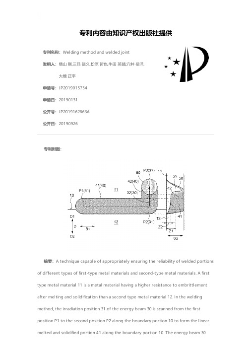
专利名称:Welding method and welded joint发明人:横山 剛,三品 徳久,松原 哲也,牛田 英晴,穴井 岳洋,大橋 正平申请号:JP2019015754申请日:20190131公开号:JP2019162663A公开日:20190926专利内容由知识产权出版社提供专利附图:摘要:A technique capable of appropriately ensuring the reliability of welded portions of different types of first-type metal materials and second-type metal materials. A first type metal material 11 is a metal material having a higher resistance to embrittlement after melting and solidification than a second type metal material 12. In the welding method, the irradiation position 31 of the energy beam 30 is scanned from the firstposition P1 to the second position P2 along the boundary portion 10 to form the linear melted and solidified portion 41 along the boundary portion 10. The energy beam 30after the first step is defined as a first side D1 in the process and the direction from the second type metal material 12 side to the first type metal material 11 side along the direction D intersecting the boundary portion 10. A second step of scanning the irradiation position 31 from the second position P2 to the third position P3 which is a position on the first side D1 from the second position P2, and ending the irradiation of the energy beam 30. [Selection] Figure 5申请人:アイシン・エィ・ダブリュ株式会社地址:愛知県安城市藤井町高根10番地国籍:JP代理人:特許業務法人R&C更多信息请下载全文后查看。
超声挤胶的英文描述

超声挤胶的英文描述Ultrasonic Dispensing: A Process for Precise Material Application and BondingUltrasonic dispensing, also known as ultrasonic gluing, is a high-precision technique utilized in various industries for dispensing adhesives, sealants, and other materials onto surfaces or for bonding two surfaces together.This innovative process involves the application of ultrasonic vibrations to the dispensing needle or nozzle, which excites the adhesive material. As a result, the material becomes more fluid and easily flows through the dispense tip. This controlled fluid flow allows for precise and uniform application, even in intricate and hard-to-reach areas.Ultrasonic dispensing offers several advantages over traditional methods. Firstly, it enables accurate application of small and consistent quantities of material, eliminating the risk of excess or insufficient adhesive. This, in turn, reduces material waste and ensures cost efficiency. Secondly, the ultrasonic vibrations promote faster curing or drying of the adhesive, resulting in shorter production cycles and increased productivity. Lastly, the process is non-contact, meaning there is no physical contact between the dispensing tool and the material or surface, minimizing the risk of contamination and damage.Common applications of ultrasonic dispensing include electronic component bonding, microelectronics assembly, medical device manufacturing, and automotive production. In electronics, this technique is used for precise encapsulation of delicate components, preventing damage from excessive heat or pressure. In medical devices, ultrasonic dispensing is employed for applying bio-compatible adhesives or sealing various components to ensure sterility and functionality. Additionally, the automotive industry relies on ultrasonic dispensing for bonding parts, sealing gaskets, and attaching electronic modules with high precision.In conclusion, ultrasonic dispensing is a cutting-edge technique that provides precise and efficient material application and bonding. With its ability to deliver accurate quantities of adhesive and promote fast curing, this process is becoming increasingly indispensable in various industries.。
热辅助超声滚压温度场参数影响激光熔覆涂层表面粗糙度研究

第53卷第5期表面技术2024年3月SURFACE TECHNOLOGY·149·热辅助超声滚压温度场参数影响激光熔覆涂层表面粗糙度研究张常胜1,沈学会1,2*,罗辉3,姜永泉4(1.齐鲁工业大学(山东省科学院) 机械与汽车工程学院,济南 250353;2.山东建筑大学机电工程学院,济南 250101;3.浙江晶鸿精密机械制造有限公司,浙江 上虞 312300;4.山东黄金矿业 (莱州) 有限公司三山岛金矿,山东 烟台 261400)摘要:目的降低激光熔覆涂层的表面粗糙度。
方法采用激光熔覆技术制备铁基激光熔覆涂层,采用超声温滚压耦合热处理工艺对熔覆层进行熔覆后强化加工,重点研究温度场参数对成形表面粗糙度的影响,通过方差分析(ANOV A)确立参数显著性,同时利用响应曲面法(RSM)构建温度场参数影响铁基涂层表面粗糙度的预测模型,并进行参数优化。
结果加热温度和保温时间对成形试样表面粗糙度的影响显著。
在实验参数范围内,试样的表面粗糙度与加热温度呈正相关,与保温时间呈负相关。
实验结果表明,在相同保温时间下,在加热温度100、250、400 ℃条件下试样的表面粗糙度Ra分别为0.237、0.158、0.096 μm;在相同加热温度下,在保温时间为0.5、1、2 h条件下试样的表面粗糙度Ra分别为0.156、0.164、0.170 μm。
可见与保温时间相比,加热温度对涂层表面粗糙度的影响更显著。
参数优化分析结果表明,在实验参数范围内,在400 ℃加热温度和0.5 h保温时间条件下,试样具有最小的表面粗糙度Ra(0.089 μm)。
结论相较于车削及常温滚压工艺,采用超声温滚压耦合热处理工艺可进一步降低激光熔覆涂层的表面粗糙度,在实验参数范围内,加热温度400 ℃和保温时间0.5 h是最优的温度场参数组合。
关键词:超声滚压;温塑性;增材制造;表面粗糙度;热处理;铁基合金中图分类号:TG379 文献标志码:A 文章编号:1001-3660(2024)05-0149-07DOI:10.16490/ki.issn.1001-3660.2024.05.015Effect of Heating Parameters on Roughness of Laser CladdingCoatings Treated by Heat-assisted Ultrasonic BurnishingZHANG Changsheng1, SHEN Xuehui1,2*, LUO Hui3, JIANG Yongquan4(1. School of Mechanical Engineering, Qilu University of Technology (Shandong Academy of Sciences), Jinan 250353, China;2. School of Mechanical and Electrical Engineering, Shandong Jianzhu University, Jinan 250101, China;3. Zhejiang Jinghong Precision Machinery Manufacturing Co., Ltd., Zhejiang Shangyu 312300, China;4. Shandong Gold Group Co., Ltd., Shandong Island Gold Mine, Shandong Yantai 261400, China)ABSTRACT: Laser cladding technique can save resource consumption, achieve rapid manufacturing and damage repair of收稿日期:2022-11-29;修订日期:2023-08-08Received:2022-11-29;Revised:2023-08-08基金项目:国家自然科学基金(51775285);山东省自然科学基金(ZR2023ME104)Fund:National Natural Science Foundation of China (51775285); Shandong Provincial Natural Science Foundation, China (ZR2023ME104)引文格式:张常胜, 沈学会, 罗辉, 等. 热辅助超声滚压温度场参数影响激光熔覆涂层表面粗糙度研究[J]. 表面技术, 2024, 53(5): 149-155.ZHANG Changsheng, SHEN Xuehui, LUO Hui, et al. Effect of Heating Parameters on Roughness of Laser Cladding Coatings Treated by Heat-assisted Ultrasonic Burnishing[J]. Surface Technology, 2024, 53(5): 149-155.*通信作者(Corresponding author)·150·表面技术 2024年3月high-end parts/components, and thus promote environmental sustainability. However, in most cases, the surface finishing of cladding parts/components cannot meet the requirements of engineering applications, and thus post-cladding processes are required. Here, a sort of post-cladding treatment, that is, ultrasonic warm burnishing coupled with sequent heat treatment (UWB/HT), was proposed and employed to treat coatings after laser cladding. Especially, based on experimental data, a prediction model of surface roughness of the studied Fe-based cladding coating was built. ANOV A and RSM methods were employed to investigate the effect of heating parameters, i.e, heating temperature and heat holding time, on roughness of laser cladding coatings treated by UWB/HT. According to result, the surface roughness of the studied coating was positively related to heating temperature. For instance, at a same holding time, the roughness values of coatings treated at 100 ℃, 250 ℃ and 400 ℃ were Ra 0.237 μm, Ra 0.158 μm and Ra 0.096 μm, respectively. Therefore, it was proved that UWB/HT process could further decrease coating roughness in comparison to traditional ultrasonic burnishing without heating treatment. However, in contrast, a long holding time was supposed to result in slight increase of coating roughness. For instance, at a same heating temperature, the roughness values of coatings treated at 0.5 h, 1 h and 2 h were Ra 0.156 μm, Ra 0.164 μm and Ra 0.170 μm, respectively. The warm plasticity of metal materials resulting from high temperature was responsible for the roughness decrease of coating treated by UWB/HT. Meanwhile, longer holding time led to somewhat deformation recovery of burnished coating and therefore resulted in slight roughness increase. According to ANOV A result, heating temperature had a more significant effect on coating roughness than holding time. Within experimental scope, the optimum parameter combination was 400 ℃ heating temperature and 0.5 h holding time, under which a least roughness value of Ra 0.089 μm was achieved.KEY WORDS: ultrasonic burnishing; warm plasticity; additive manufacturing; surface roughness; heat treatment; Fe-based alloy作为实现可持续制造的重要技术手段之一,增材制造(Additive Manufacturing, AM)技术在工业领域及学术界受到越来越多的关注[1]。
预热辅助下超声滚焊异种材料连接工艺

专题研究预热辅助下超声滚焊异种材料连接工艺周荣稳,李昌徽(山东宏源信泰检验检测集团有限公司,山东青岛266000)摘要:在Al/Cu异种材料焊接时,由于本身性能有较大差别,特别是物理和化学性能,这是焊接的困难所在,固相焊中的超声波滚焊焊接方法特别适合异种材料的焊接%文中采用TG电弧预热减小焊接时工件温差和超声波滚焊工艺结合在一起使用,此方法下,TIG电弧的预热和超声波振动机械能的共同作用可以有效提高该焊接方法的焊接能力。
在试验的过程中改变输入的电流值,对各种参数下的异种材料滚焊接头进行全面的比对分析,发现异种材料之间的超声波滚焊过程是一种基于焊接区金属充分贴合、塑性变形、机械嵌合及界面区原子扩散与键合等作用的焊接过程,实现了A/C u异种材料超声波滚焊连接%关键词:A/Cu异种材料;TIG电弧预热;超声波滚焊;机械嵌合中图分类号:TG44Preheah aided by ultrasonic seam welding connectingin s nmnuarmaeernausee$enouogyZhou Rongwen,Li Changhui(Shandong Hongyuan Xintai Inspection and Testing Group Co.,Ltd.,Qingdao266000,Shandong,China)Abstraci:In ths A/Cu dissiminf mateaals welding,because theO own perfor^lanco is quits dOferent,especial l y ths physical and chemiccl propeOies,which is welding diOicu/Ws.Ultrasonic rolling welding in so C/phase welding is especially suitable foe welding heterogeneous mateaals.In this papse,TIG are preheating is adopted to rs-ducc ths temperature dmferenca between ths workpiecc and ultrasonic rolling welding process.Under this method, eh7joineaceion oeeh7peh7aeingoeTIGaecand eh7m7chanicaa7n7egyoeuaeeasoniceibeaeion can7e ceie7ayimC peoe7eh7w7adingcapacieyoeehisw7adingm7ehod.Changingeh7inpuecu e neeaau7in eh7peoc7s oeeh7eseeC suaes,eh7eaeiouspaeam7eesoeeo a ingdi s imiaaemaeeiaasw7adingh7ad eoconduceacompeh7nsie7compaeaeie7 anaaysis,ieiseound7d ehaeuaeeasonics7amw7adingpeoc7s b7ew77n di s imiaaemaeeiaasisakind oebas7d on eu a y joinew7ad eon7m7eaas,paaseicd7eoemaeion and m7chanicaachim7eicand aeomicdi e u sion in eh7ineeeac7aeaand ths bonding effect of welding process,which realizes ths A/Cu ultrasonic seam welding of dissimi/r mateeals.Key words:A/C u heterogeneous mateaals;TIG are preheating;ultrasonic rolling welding;mechanical00X00前言在A/Cu异种材料焊接时,成功案例和经验较少,实际应用中两者焊接特别困难。
材料+翻译文献
等离子弧焊接时2205双相不锈钢焊接性能研究摘要:这篇文章报道了使用等离子弧焊焊接2205双相不锈钢对接接头的最适宜焊接条件(焊接强度和运行速度)的确定。
恰当操作和冶金学焊接性能的最小净能量输入是用两种不同的焊接模式来研究的:熔焊或传导模式和小孔模式。
每一种模式的焊接参数对尺寸、焊接点塑造以及它们的铁氧体含量的影响也做了研究。
关键字:等离子弧焊接; 双相不锈钢; 小孔;可焊性1、引言得益于双相不锈钢良好的抗腐蚀特征和优越机械性能的的结合,它的使用一直在增长,尤其是在温度敏感部件,例如热交换机和化学与石油化工产业中的化学反应器。
优良的机械性能(高强度高韧性的结合)和双相结构中奥氏体和铁氧体的平衡比例相关,这个比例通常是50/50。
鉴于双相不锈钢使用量的增加,我们需要更好地了解那些影响焊接性能的冶金因素。
施工装配所需要的传统熔焊过程对二相结构有明显影响,在熔合区和热影响区都产生影响。
众所周知,随着热影响区δ铁氧体的增加,双相不锈钢焊接点上的冲击韧性会减小,因此普通的双相结构通过热循环中的高峰值温度和快速冷却率来强化铁氧体化。
熔焊中和这些材料相关的另一个问题是凝固裂纹的脆弱性,这比304L奥氏体不锈钢的要大。
不良相中的金属化合物,碳化合物和氮化合物的析出能够引起韧性和抗腐蚀性的急剧恶化,例如在σ期,具有快速形成的动力学特征。
因此在焊接阶段通过控制熔合区和热影响区的时间平衡来保持二相结构优势的连续性是非常必要的。
对于这种焊接街头的实际应用,熔合区内铁氧体的适当比例在30%—70%。
铁氧体的含量依赖于熔合区的化学成分和焊接点的冷却速率,这和焊接过程中能量的输入相关。
出于这个原因,本研究旨在确定当控制能量输入时双相不锈钢氧炔焊(无填料)的最佳条件。
表12205(UNS S32205)双相不锈钢组成(in wt.%)组成 (wt.%)C 0.020Si 0.40P 0.021Cr 22.37Ni 5.74Mo 3.20Cu 0.17N 0.171Nb 0.05Mn 1.52S 0.001Fe的含量得到了平衡。
- 1、下载文档前请自行甄别文档内容的完整性,平台不提供额外的编辑、内容补充、找答案等附加服务。
- 2、"仅部分预览"的文档,不可在线预览部分如存在完整性等问题,可反馈申请退款(可完整预览的文档不适用该条件!)。
- 3、如文档侵犯您的权益,请联系客服反馈,我们会尽快为您处理(人工客服工作时间:9:00-18:30)。
Journal of Materials Processing Technology 211 (2011) 1358–1363Contents lists available at ScienceDirectJournal of Materials ProcessingTechnologyj o u r n a l h o m e p a g e :w w w.e l s e v i e r.c o m /l o c a t e /j m a t p r o t ecUltrasonic weld properties of heterogeneous polymers:Polylactide and poly (methyl methacrylate)Guohong Zhang a ,Jianhui Qiu a ,∗,Liang Shao b ,Mingzhu Liu b ,Min Zhang c ,Yongbo Wu aaDepartment of Machine Intelligence and Systems Engineering,Faculty of Systems Engineering,Akita Prefectural University,Akita 015-0055,Japan bCollege of Chemistry and Chemical Engineering,Lanzhou University,Lanzhou 730000,PR China cInstitute of Chemistry and Chemical Engineering,Shaanxi University of Science and Technology,Xi’an,Shaanxi 710021,PR Chinaa r t i c l e i n f o Article history:Received 3August 2010Received in revised form 1February 2011Accepted 5March 2011Available online 15 March 2011Keywords:PolylactidePoly (methyl methacrylate)Ultrasonic weld Welding strengthInterposed sheet (IPS)a b s t r a c tThis paper aims to investigate the effects of welding conditions and the correlation between welding strengths and interfaces structures on the weld between polylactide (PLA)and poly (methyl methacrylate)(PMMA).Using our proposed ultrasonic weld (USW)method,PLA and PMMA composites (PLA/PMMA)are valid to employ as interposed sheet (IPS)experimentally.There are optimum welding times and welding presses depending on the peak welding strengths.The maximum welding strength can reach as high as 90%of the tensile strength of the matrix PLA,while the welding time is 4s and welding press is 0.6MPa.But excessive welding presses are deleterious to the weld,and it can also bring IPS destroying during the weld work.© 2011 Elsevier B.V. All rights reserved.1.IntroductionUltrasonic welding (USW)for plastics is a joining technique without additional,foreign substances,such as adhesives or sol-vents,with well defined local heating of only the joint area,with short cycle times in the range of just a few seconds and on com-paratively cost effective machines (Truckenmüller et al.,2006).During ultrasonic consolidation process,energy generated from an ultrasonic transducer is transferred to a workpiece through a conotrode in the form of ultrasonic oscillation (Li and Soar,2009).Conventionally,ultrasonic weld (USW)techniques have always been used between only identical polymers (Qiu et al.,2009).Recently,welding immiscible polymers with a supercriti-cal fluid (Wang et al.,2007)is reported.However,welds between heterogeneous materials and substances are largely necessary in various fields and paid much attention to in the latest days (Kocabekir et al.,2008).However,so far there is no method for weld between heterogeneous polymers but almost only adhe-sive way which usually brings the problems such as durability,heat resistance (The Adhesion Society of Japan,2004),poi-sonous character and environmental hormone (Brockmann et al.,2009).∗Corresponding author.Tel.:+81184272134;fax:+81184272134.E-mail address:qiu@akita-pu.ac.jp (J.Qiu).Use our new USW that inserting an interposed sheet (IPS)between the two work pieces (WPs)may solve the problems above.This method (Qiu et al.,2007)is that through the ultrasonic vibra-tion of IPS,the frictional heat can be produced at the interfaces between IPS and WPs and melts the polymer.After the polymers solidify again,the welds are achieved.For many polymer,the mold-ing method are used as injection molding (An and Chen,2008).In our method,IPS is also made by injection molding method,the properties of molding process have been discussed by many researchers (Qiu and Wu,2007).A biodegradable polymer,polylactide (PLA,crystalline)has been used for biomedical applications,such as drug-delivery systems,implant materials for bone fixation,and surgical sutures because of its good biocompatibility and nontoxicity (Zhang et al.,2003).Additionally,PLA is useful for welding with other polymers,espe-cially in the areas in which adhesions are limited (Viljanmaa et al.,2003).Poly (methyl methacrylate)(PMMA)is an amorphous poly-mer which has been widely used because of its good engineering properties.Joints between these two polymers (amorphous and crystalline,transparent and not)are significative and helpful to investigate the weld mechanism.A weld line is not a line as the name suggests but a three dimen-sional region with complex morphology (Merah et al.,2004).In the present paper,we have achieved the weld between PLA and PMMA and the effects of welding conditions and the correlation between welding strengths and interfaces structures (weld line morphology)are investigated.0924-0136/$–see front matter © 2011 Elsevier B.V. All rights reserved.doi:10.1016/j.jmatprotec.2011.03.005G.Zhang et al./Journal of Materials Processing Technology211 (2011) 1358–13631359Fig.1.Novel USW principle schematic drawing.2.Materials and experimental methods2.1.Materials and WPsCrystalline PLA(L-PLA,Unitika Ltd.,Japan)with melting point of170◦C and amorphous PMMA(MD,Mitsubishi Rayon CO.,Ltd., Japan)are used as matrix polymers.Wps of PLA and PMMA are made using an injection molding machine(FANUC Ltd.,ROBOSHOT S2000i100A)in a half shape dumbbell(half of JIS1).The molding conditions for PLA are extrusion temperature(nozzle temperature) of190◦C,extrusion rate of20%,mold temperature of40◦C and cooling time of30s and those of PMMA are extrusion tempera-ture(nozzle temperature)of230◦C,extrusion rate of17%,mold temperature of40◦C and cooling time of30s.2.2.IPS preparationThe materials of IPS are made by PLA and PMMA compos-ite(PLA/PMMA)according to the injection molding.PLA/PMMA is firstly molded as dumbbell(JIS1)with PLA and PMMA at1:1volume ratio.The molding conditions are nozzle temperature of190◦C, extrusion rate of15%,mold temperature of40◦C and cooling time of30s.After molding again to modify its thickness to1mm with the hot-press machine(Imoto Ltd.,molding parameters:tempera-ture of200◦C and heating time of10min),the plastic layers are cut as a rectangle(12mm×8mm×1mm;length×width×thickness) in order to install them on the IPS holder of the apparatus.In the front edge at the middle of the IPS,a3mm diameter hole is drill for fixing in place with a screw.2.3.Ultrasonic weldAs is shown in Fig.1,WPs(made of PLA and PMMA)arefixed on the IPS holders of the slide guide,and the IPS is installed on the IPS holder with the screw.After IPS is laid between the two WPs, welding presses are given and the joints begin.Welding conditions are as follows:frequency of28kHz,amplitude of30m,vibrating time from1.0s to5.0s,and welding press from0.1MPa to0.6MPa. Moreover,the length from thefixing point to the welding surface (called the protruded length)is set to10mm to lessen the deflec-tion effect.To get uniform surface roughness of about Ra=0.2m, abrasive paper is placed on slide guide in the verticaldirection.Fig.2.Nominal strain versus nominal stress of PLA,PMMA and composite of PLA/PMMA.3.Measurements and characteristics3.1.Tests of tensile and welding strengthsTests of tensile and welding strengths are carried out using a universal tester(Instron Model Series3360)at the crosshead speed of5mm/min and temperature of23◦C±2◦C.The correlation of the load,deformation and the curve of nominal stress and strain can be calculated,and the breaking stress can also be obtained from the peak load.3.2.Rupture surface analysisThe rupture surfaces before and after tensile tests are observed using a scanning electron microscope(SEM;Hitachi,Model S-4300) to analyze the correlation of interfacial morphology and strength. For the SEM observations,specimens are needed to modify a Pt and Au coating on surface.3.3.Surface temperature measurementsIn order to observe the welding process and the change of the interfacial temperature,measurements are made with infrared radiation thermometers(Chino Corp.,Model CPA-SC620),where the frame time is30Hz,and resolving power is640×480Video Format.Together with a FT IR system(ThermaCAM Researcher Pro.2.8),the highest surface temperatures of interfaces can be obtained where the region is chosen in advance.4.Results and discussion4.1.Mechanical properties of PLA,PMMA and PLA/PMMA compositeFig.2plots of nominal strain versus nominal stress of the three materials.The yield strengths of PLA and PMMA are58MPa and 65MPa,respectively,and the nominal strains are all about10%, showing a brittle characteristic.For the PLA/PMMA composite,the yield strength is significantly enhanced to73MPa which is over18% than that of PLA.Moreover,the nominal strain approaches180%, showing a typical ductile characteristic.This indicates that the strength and plasticity of the PLA/PMMA have been much enhanced compared with the matrix polymers.From the SEM photo shown in Fig.3at rupture surface of PLA/PMMA,we can see that the two materials are very compatible,there are only plastic deformations and no phase separation.1360G.Zhang et al./Journal of Materials Processing Technology211 (2011) 1358–1363Fig.3.SEM photo at rupture surface of PLA/PMMA.Fig.4plots the TG curves of the three materials.The decom-position temperatures(the temperature at the weight loss of2%) are close to each other,about320◦C.This suggests that the ther-mal properties of the composite are almost the same as the matrix polymers,and the decomposition temperature has not changed a lot.That is to say,when welding,IPS cannot decompose before the matrixes.The mechanical properties of PLA/PMMA are enhanced very much,especially the change from brittle to ductile.The IPS made of PLA/PMMA will not cause any loss of welding strength.Further,it can also relax the residual stress given after welding and improve welding performance due to its excellent plasticity.Therefore,the following experiments use PLA/PMMA as IPS to weld.4.2.Welding time effects on welding strengthEffects of welding time on welding strength are shown in Fig.5. We can see that the welding strength is generally increased with welding time prolonging when welding press is0.1MPa.When the welding press is set to0.3MPa,the peak welding strength of 47MPa can be obtained at welding time of3s,and when the weld-ing press is set to0.6MPa the peak welding strength of45MPa can be obtained at4s.Then the welding strength decreases as the welding time continue increasing.That is to say,the peak welding strengths can be achieved at the optimum welding times.We can also conclude that no matter how big the welding presses are set, the welding strength is about33MPa at welding time of5s.In addi-tion,with the welding press increasing,the peak strength shouldfirst reach normally.But when the welding press is0.6MPa,ithasFig.4.TG curves of PLA,PMMA,andPLA/PMMA.Fig.5.Effects of welding time on welding strengths.taken longer time(4s)than the one of0.3MPa.The reasons will beexplained in Figs.10and11.The SEM photos of the rupture surfaces of welded inter-faces when welding press is0.3MPa are shown in Fig.6.FromFigs.5and6,due to the short welding time(below3s,Figs.6(a)and(b)),there is only a little heat,the non-welded areas are broadand the strengths are weak.With the welding time increasing,thenon-welded areas shrink and the strengths enhance accordingly.The welding time of3s(Fig.6(c))is critical,the frictional heat riseis large and the peak welding strength can be obtained.The reasonmay be that they rupture in the PLA matrix and the work piecesshow the constriction at the middle part,resulting in the rupturesurface shrinking.Then,when welding times prolong again,due tothe weld for a long time under a high temperature,they are mainlyrupture of IPS(Fig.6(d)).That is to say,excessively long weldingtime is not good for weld.4.3.Welding press effects on welding strengthEffects of welding press on welding strength are shown in Fig.7.Welding strength is enhanced earlier as the welding presses golarger and the peak strength occurs at welding press of0.4MPawhen the welding times are1s and2s.After that,the strengthweakens.When welding time is4s,the strengths are also enhancedwith the press increasing.But from0.4MPa to0.6MPa,the effectturns to be low.Usually,when the welding press increases,the friction isinspired much,heating is acute and the weld can be achieved dueto sufficient melting.When the welding presses are too small,thefrictional heat produces a little and the interfacial temperatures arelow.When the welding presses are too large,the frictional heat isacute accordingly,resulting to the small ultrasonic amplitude andthe interfacial temperatures can also be low.Therefore,the weld-ing press has an optimum value.For the presses of0.3MPa and0.6MPa,the temperatures at1s are low and the strengths are weak.So the press of0.4MPa may be the better press and even though atthe welding time of1s,the welding strengths are strong enough.When the welding areas cover the whole surface of the interface,the strengths can also reach the peak value.Moreover,as the presscontinues to increase,the frictional heat is getting too much whichcause the high temperature and polymer decomposition.Finally,air bubbles are produced in the interfaces,resulting weak weldingstrengths.The rupture surfaces of welded interfaces for welding time of2sare shown in Fig.8(a)and(b)when the welding presses are0.3MPaand0.6MPa,respectively.There is a non-welding part(Fig.8(a))G.Zhang et al./Journal of Materials Processing Technology211 (2011) 1358–13631361Fig.6.Rupture surfaces of welded interfaces when welding press is0.3MPa,with the welding time of:(a)1s,(b)2s,(c)3s and(d)5s.Fig.7.Effects of welding press on welding strengths.due to insufficient heating.Fig.8(b)shows that bubbles are resulted from overheating temperature which affects the welding strengths.The strengths for welding time of4s are obviously enhanced compared with the ones at times of1s and2s.There is no peak strength when the presses go up.But the strengths are sharply enhanced earlier and from0.4MPa the strengths increase mildly. We believe that from0.1MPa to0.4MPa,the strengths become high due to the more frictional heat.But at the welding press of0.4MPa(Fig.9(a)),the welded areas are extended resulting in higher strengths.At the welding press of0.6MPa(Fig.9(b)),the bubbles are caused by too large welding press.Because of the slightly longer welding time of4s,the bubbles mixing with the melted materials are squeezed out of the interfaces.Finally,the interfaces become smooth,so the two strengths(for welding press of0.4MPa and0.6MPa)are all whole surface joint and they are nearly the peak strengths as above.4.4.Analysis of interfacial temperature and weld mechanismThe peak surface temperatures around the interfaces are shown in Fig.10for welding time of5s and welding press of0.3MPa.We have also tested all the welds at various welding time when welding press is0.3MPa.The curves share the same peak temperature and are different from the time of the temperature begin to low down, where the temperature would turn down once the vibration is over. From Fig.10we see an inflexion at welding time of1s(the surface temperature is about100◦C).After that the temperature increases sharply and from1.5s the temperature reaches the highest value of210◦C until the vibration is stopped(5s)finally.From the results above,we can conclude that when the weld-ing time is below1s,the surface temperatures cannot reachthe Fig.8.Rupture surfaces of welded interfaces when welding time is2s,with the welding presses of:(a)0.3MPa and(b)0.6MPa.1362G.Zhang et al./Journal of Materials Processing Technology211 (2011) 1358–1363Fig.9.Rupture surfaces of welded interfaces under welding time of 4s,with the welding press of:(a)0.4MPa and (b)0.6MPa.melting points of the materials,so the weld cannot be formed.Because these temperatures are the surface temperatures accord-ing to the instrument,the top temperature must be the temperature of melted polymer.So the constant top temperature value is sug-gested that the melted materials are squeezed out of the interfaces continuously.At 2s,the surface temperature has just reached the maximum.The polymers are starting to melt,and the diffusion of molecules is also just beginning,the weld is not the whole surface weld.At 3s,the interfacial parts have melted enough,the bubbles and melted materials are squeezing out of the interfaces,which can help to make the interfaces smooth.At this time,the peak strengths are obtained.If welding time continues prolonging,the surface is covered by the melted materials,and the inner tempera-ture may be much higher,especially at the later weld,the materials may decompose due to the overheating temperature keeping a long time.Finally,the strengths turn lower.This is the reason whytheFig.10.The top surficial temperatures around interfaces under welding time of 5s and welding press of 0.3MPa.Fig.11.The top surficial temperatures around interfaces under welding time of 5s and welding press of 0.6MPa.strengths of specimens welded for 4s and 5s decreasing when the welding press is 0.3MPa.The peak surface temperatures around interfaces are shown in Fig.11for welding time of 5s and welding press of 0.6MPa.Also,the temperatures of weld at other welding times are tested and the peak temperatures are all similar to Fig.11.Further,we see an inflexion at welding time of 1s,like the curve of Fig.10above.The temperatures rise sharply and reach the first peak tempera-ture until about 3s.Then,the temperature reaches the second (the highest)value 210◦C and keep until the vibration stop (5s).From the results above,we can conclude that no matter whether the welding press is (0.3MPa or 0.6MPa),there is one inflexion at welding time of 1s,then the temperature continues to rise.That is to say,the weld cannot be achieved before 1s.Due to the lower interfacial temperature,when welding time prolong,the welding presses are so large that the IPS has been destroyed and the weld cannot achieve due to the friction has been stopped.Therefore,the temperatures decrease when the welding time is about 3s.If the welds stop at 3s,the disfigurements produce easily and remain at the interfaces,resulting to the weak welding strengths.With the welding times turns longer to 4s,the melted polymers have enough time to fill in the space of the interfaces,which prevent the disfigurements remaining.It is indicated that the strengths at 3s are much weaker and temperatures decrease due to the IPS being destroyed which does not enhance the welding strengths.These are the reasons why the peak strengths are at 4s for specimens welded at 0.6MPa compared with 3s for 0.3MPa.5.ConclusionsThe effects of welding conditions and the correlation between welding strengths and interfaces structures on the weld between polylactide (PLA)and poly (methyl methacrylate)(PMMA)are ing our proposed ultrasonic weld (USW)method,PLA/PMMA composites are valid to employ as interposed sheet (IPS)experi-mentally.There are optimum welding times and welding presses depending on the peak welding strengths.The maximum weld-ing strength can reach as high as 90%of the tensile strength of the matrix PLA,while the welding time is 4s and welding press is 0.6MPa.But excessive welding presses are deleterious to the weld,and it can also bring IPS to be destroyed easily during the weld work.G.Zhang et al./Journal of Materials Processing Technology211 (2011) 1358–13631363AcknowledgementsThis work was supported by the Japan Society for the Promotion of Science for the supply by the basic research program C,Grant-in-Aid for Scientific Research,2007–2008.The authors would like to acknowledge the Japan Society for the Promotion of Science for their help.ReferencesAn,C.-C.,Chen,R.-H.,2008.The experimental study on the defects occurrence of SL mold in injection molding.J.Mater.Process.Technol.201,706–709. Brockmann,W.,GeiB,P.L.,Klingen,J.,Schroder,B.,2009.Adhesive Bonding:Mate-rials Applications and Technology.Wiley-VCH.Kocabekir,B.,Kacar,R.,Gündüz,S.,Hayat,F.,2008.An effect of heat input,weld atmosphere and weld cooling conditions on the resistance spot weldability of 316L austenitic stainless steel.J.Mater.Process.Technol.195,327–335.Li,D.,Soar,R.,2009.Influence of sonotrode texture on the performance of an ultra-sonic consolidation machine and the interfacial bond strength.J.Mater.Process.Technol.209,1627–1634.Merah,N.,Irfan-ul-Haq,M.,Khan,Z.,2004.Effects of injection molding weld on fatigue crack resistance of CPVC at different temperatures.J.Mater.Process.Technol.155-156,1261–1265.Qiu,J.H.,Wu,Y.,2007.Japan Patent pending,2007-156866.Qiu,J.H.,Zhang,G.,Wu,Y.,2009.Proposal of ultrasonic welding technique and weld performances applied to polymers.Polym.Eng.Sci.49(9),1755–1759.Qiu,J.H.,Tsuboi,A.,Izumi,K.,Wu,H.,Guo,S.,Huang,Y.,2007.Effects of interfacial morphology on the welding strength of injection-molded polyamide.Polym.Eng.Sci.47(12),2164–2171.Truckenmüller,R.,Ahrens,R.,Cheng,Y.,Fischer,G.,Saile,V.,2006.An ultrasonic welding based process for building up a new class of inertfluidic microsensors and actuators from polymers.Sens.Actuators A132,385–392.The Adhesion Society of Japan,2004.Adhesion Technology Book for Tyros. Viljanmaa,M.,Södergård,A.,Törmälä,P.,2003.The use of lactic acid-based hot melt adhesive in the industrial lamination process.Int.J.Adhes.Adhes.23(2), 151–154.Wang,X.C.,Sanchez,I.C.,2007.Welding immiscible polymers with a supercritical flngmuir23(24),12192–12195.Zhang,G.,Zhang,J.,Wang,S.,Shen,D.,2003.Miscibility and phase structure of binary blends of polylactide and poly(methyl methacrylate).J.Polym.Sci.:Part B:Polym.Phys.41,23–30.。