全国建筑地下渗漏率达57.51% 楼倒地陷暴露渗漏黑洞
爱国者h5说明书
HIKVISION DS-2CD3B26G2T-IZHS(Y) 2 MP DarkFighter V

DS-2CD3B26G2T-IZHS(Y)2 MP DarkFighter Varifocal Bullet Network CameraEmpowered by deep learning algorithms, Hikvision AcuSense technology brings human and vehicle targets classification alarms to front- and back-end devices. The system focuses on human and vehicle targets, vastly improving alarm efficiency and effectiveness.Hikvision has been dedicated to develop products with security since established. Hikvision always follows security by design principle and has adopted many methods of security technologies into our product development lifecycle, including terminal security, data security, application security, network security, and privacy protection. In the meantime, the security technologies used by Hikvision are all in compliance with local applicable laws and safety regulations. These securitymeasures could enhance product's cyber security protection capability and protect your devices as well as your data from malicious cyber attacks.⏹Supports Hikvision Embedded Open Platform (HEOP) and importing third party applications ⏹ Supports 1.5 Tops computing power, 60 MB system memory, 400 MB smart RAM, and 2 GB eMMC storage for sharing resources⏹High quality imaging with 2 MP resolution ⏹Excellent low-light performance with DarkFighter technology ⏹Focus on human and vehicle targets classification based on deep learning ⏹Efficient H.265+ compression technology ⏹Clear imaging against strong back light due to 140 dB WDR technology ⏹Motorized varifocal lens for easy installation ⏹Audio and alarm interface available ⏹Water and dust resistant (IP67) and vandal-resistant (IK10) ⏹ -Y: Anti-Corrosion: NEMA 4X: NEMA 250-2014SpecificationCameraImage Sensor 1/1.8" Progressive Scan CMOSMin. Illumination Color: 0.0014 Lux @ (F1.4, AGC ON),B/W: 0 Lux with IRMax. Resolution 1920 × 1080Day & Night IR cut filterShutter Time 1/3 s to 1/100,000 sAngle Adjustment Pan: 0° to 355°,tilt: 0° to 90°,rotate: 0° to 360°LensLens Type Varifocal lens, motorized lens, 2.8 to 12 mm and 8 to 32 mm optionalFocal Length & FOV 2.8 to 12 mm: horizontal FOV 114° to 41.8°, vertical FOV 59.3° to 23.6°, diagonal FOV 141.3° to 48.1°8 to 32 mm: horizontal FOV 42.5° to 15.2°, vertical FOV 23.4° to 8.7°, diagonal FOV 49.7° to 17.3°Aperture 2.8 to 12 mm: F1.4; 8 to 32 mm: F1.7 Lens Mount IntegratedFocus Auto, Semi-auto, ManualDepth of Field 2.8 to 12 mm: 1.5 m to ∞8 to 32 mm: 7.5 m to ∞Iris Type P-iris DORIDORI 2.8 to 12 mm: D: 60 to 149 m, O: 23.8 to 59.1 m, R: 12 to 29.8 m, I: 6 to 14.9 m 8 to 32 mm: D: 150.3 to 400 m, O: 59.7 to 158.7 m, R: 30.1 to 80 m, I: 15 to 40 mIlluminatorIR Wavelength 850 nmSupplement Light Range 2.8 to 12 mm: up to 60 m; 8 to 32 mm: up to 80 m Smart Supplement Light YesSupplement Light Type IRHEOPOpen Resources Memory: 60 MB, Smart RAM: 400 MB, eMMC: 2 GBComputing Power 1.5 TOPSOpen Capability HEOP 2.0 OpendevSDKDeep Learning Structure Caffe,PyTorch,TensorFlow,PaddlePaddle,ONNX Programming Language C,C++VideoMain Stream 50 Hz: 25 fps (1920 × 1080, 1280 × 720) 60 Hz: 30 fps (1920 × 1080, 1280 × 720)Sub-Stream 50 Hz: 25 fps (640 × 480, 640 × 360) 60 Hz: 30 fps (640 × 480, 640 × 360)Third Stream 50 Hz: 10 fps (1920 × 1080, 1280 × 720, 640 × 480, 640 × 360) 60 Hz: 10 fps (1920 × 1080, 1280 × 720, 640 × 480, 640 × 360)Fourth Stream 50 Hz: 10 fps (1280 × 720, 640 × 480, 640 × 360) 60 Hz: 10 fps (1280 × 720, 640 × 480, 640 × 360)Video Compression Main stream: H.265/H.264/H.264+/H.265+, Sub-stream: H.265/H.264/MJPEG,Third stream: H.265/H.264,Fourth stream: H.265/H.264/MJPEGVideo Bit Rate 32 Kbps to 8 MbpsH.264 Type Baseline Profile,Main Profile,High ProfileH.265 Type Main ProfileBit Rate Control CBR,VBRScalable Video Coding (SVC) H.264 and H.265 encodingRegion of Interest (ROI) 5 fixed regions for main stream and sub-stream Target Cropping Yese-PTZ Support Preset and Auto Tracking settings AudioAudio Type Mono soundAudio Compression G.711/G.722.1/G.726/MP2L2/PCM/MP3/AAC-LCAudio Bit Rate 64 Kbps (G.711ulaw/G.711alaw)/16 Kbps (G.722.1)/16 Kbps (G.726)/32 to 192 Kbps (MP2L2)/8 to 320 Kbps (MP3)/16 to 64 Kbps (AAC-LC)Audio Sampling Rate 8 kHz/16 kHz/32 kHz/44.1 kHz/48 kHz Environment Noise Filtering YesNetworkProtocols TCP/IP, ICMP, HTTP, HTTPS, FTP, DHCP, DNS, DDNS, RTP, RTSP, NTP, UPnP, SMTP, IGMP, 802.1X, QoS, IPv4, IPv6, UDP, Bonjour, SSL/TLS, PPPoE, SFTP, ARP, SNMP, WebSocket, WebSockets, SRTPSimultaneous Live View Up to 6 channelsAPI ONVIF (Profile S, Profile G, Profile T),ISAPI,SDK,ISUPUser/Host Up to 32 users3 user levels: administrator, operator, and userSecurity Password protection, complicated password, HTTPS encryption, 802.1X authentication (EAP-TLS, EAP-LEAP, EAP-MD5), watermark, IP address filter, basic and digest authentication for HTTP/HTTPS, WSSE and digest authentication for Open Network Video Interface, RTP/RTSP over HTTPS, control timeout settings, security audit log, TLS 1.1/1.2/1.3, host authentication (MAC address)Network Storage NAS (NFS, SMB/CIFS),Auto Network Replenishment (ANR),Together with high-end Hikvision memory card, memory card encryption and health detection are supported.Client iVMS-4200,Hik-Connect,Hik-CentralWeb Browser Plug-in required live view: IE 10, IE 11,Plug-in free live view: Chrome 57.0+, Firefox 52.0+, Edge 89+, Local service: Chrome 57.0+, Firefox 52.0+, Edge 89+ImageImage Parameters Switch YesImage Settings Rotate mode,saturation,brightness,contrast,sharpness,gain,white balance,adjustable by client software or web browserDay/Night Switch Day,Night,Auto,Schedule Wide Dynamic Range (WDR) 140 dBImage Enhancement BLC,HLC,3D DNR,DefogSNR ≥ 52 dBPrivacy Mask 4 programmable polygon privacy masks InterfaceAlarm 3 inputs, 3 outputs (max. 24 VDC/24 VAC, 1 A)Audio 1 input (line in), two-core terminal block, max. input amplitude: 3.3 Vpp, input impedance: 2.2 KΩ, interface type: non-equilibrium,1 output (line out), two-core terminal block, max. output amplitude: 3.3 Vpp, output impedance: 100 Ω, interface type: non-equilibriumEthernet Interface 1 RJ45 10 M/100 M self-adaptive Ethernet portOn-Board Storage Built-in memory card slot, support microSD/microSDHC/microSDXC card, up to 512 GB Reset Key YesRS-485 1 RS-485 (Half duplex, HIKVISION, Pelco-P, Pelco-D, self-adaptive)Power Output 12 VDC, max. 100 mAEventBasic Event Motion detection (support alarm triggering by specified target types (human and vehicle)),video tampering alarm,exceptionSmart Event scene change detection,audio exception detection,defocus detection, unattended baggage detection,object removal detectionLinkage Upload to FTP/NAS/memory card,notify surveillance center,send email,trigger alarm output,trigger recording,trigger capture,audible warningDeep Learning FunctionFace Capture Yes People Counting YesPerimeter Protection Line crossing, intrusion, region entrance, region exitingSupport alarm triggered by specified target types (human and vehicle)GeneralPower 12 VDC ± 25%, 1.20 A, max. 14 W, 24 VAC ± 20%, 1.03 A, max. 14 W, two-core terminal block,PoE: IEEE 802.3at, Class 4, max. 17 WMaterial Aluminum alloy bodyDimension Ø105 mm × 340.7 mm (Ø4.1" × 13.4")Package Dimension 385 mm × 190 mm × 180 mm (15.2" × 7.5" × 7.1")Weight Approx. 1450 g (2.9 lb.)With Package Weight Approx. 2261 g (4.9 lb.)Storage Conditions -40 °C to 60 °C (-40 °F to 140 °F). Humidity 95% or less (non-condensing) Startup and OperatingConditions-40 °C to 60 °C (-40 °F to 140 °F). Humidity 95% or less (non-condensing) General Function Heartbeat,anti-banding,mirror,flash log,password reset via email,pixel counterLanguage 33 languages: English, Russian, Estonian, Bulgarian, Hungarian, Greek, German, Italian, Czech, Slovak, French, Polish, Dutch, Portuguese, Spanish, Romanian, Danish, Swedish, Norwegian, Finnish, Croatian, Slovenian, Serbian, Turkish, Korean, Traditional Chinese, Thai, Vietnamese, Japanese, Latvian, Lithuanian, Portuguese (Brazil), UkrainianHeater YesApprovalEMC FCC: 47 CFR Part 15, Subpart B,CE-EMC: EN 55032: 2015, EN 61000-3-2:2019, EN 61000-3-3: 2013+A1:2019, EN 50130-4: 2011 +A1: 2014,RCM: AS/NZS CISPR 32: 2015,IC: ICES-003: Issue 7,KC: KN32: 2015, KN35: 2015Safety UL: UL 62368-1,CB: IEC 62368-1: 2014+A11,CE-LVD: EN 62368-1: 2014/A11: 2017,BIS: IS 13252 (Part 1): 2010/IEC 60950-1: 2005, LOA: IEC/EN 60950-1Environment CE-RoHS: 2011/65/EU,WEEE: 2012/19/EU,Reach: Regulation (EC) No 1907/2006Protection IP67: IEC 60529-2013,IK10: IEC 62262:2002Anti-Corrosion Protection -Y: NEMA 4X (NEMA 250-2018)⏹Typical ApplicationHikvision products are classified into three levels according to their anti-corrosion performance. Refer to the following description to choose for your using environment.With -Y model: MODERATE PROTECTIONWithout -Y model: NO SPECIFIC PROTECTION.Level DescriptionTop-level protection Hikvision products at this level are equipped for use in areas where professional anti-corrosion protection is a must. Typical application scenarios include coastlines, docks,chemical plants, and more.Moderate protection Hikvision products at this level are equipped for use in areas with moderate anti-corrosion demands. Typical application scenarios include coastal areas about 2kilometers (1.24 miles) away from coastlines, as well as areas affected by acid rain.No specific protection Hikvision products at this level are equipped for use in areas where no specific anti-corrosion protection is needed.⏹Available ModelDS-2CD3B26G2T-IZHSY(8-32mm)(H)DS-2CD3B26G2T-IZHSY(2.8-12mm)(H)DS-2CD3B26G2T-IZHS(8-32mm)(H)DS-2CD3B26G2T-IZHS(2.8-12mm)(H)⏹Dimension⏹Accessory⏹With -Y Model:⏹IncludedDS-1260ZJ-ACJunction Box⏹OptionalDS-1275ZJ-YVertical Pole MountWithout -Y Model:⏹IncludedDS-1260ZJJunction Box ⏹OptionalDS-1276ZJ-SUSCorner MountDS-1275ZJ-SUSVertical Pole MountDS-1275ZJ-S-SUSVertical Pole Mount。
W25Q128JVSIQ规格书_W25Q128JVSIQ中文资料_W25Q128JVSIQ Datasheet

Publication Release Date: May 02, 2017Revision D3V 128M-BITSERIAL FLASH MEMORY WITH DUAL/QUAD SPI- 1 -Table of Contents1. GENERAL DESCRIPTIONS ............................................................................................................. 42. FEATURES ....................................................................................................................................... 43.PACKAGE TYPES AND PIN CONFIGURATIONS ........................................................................... 5 3.1 Pin Configuration SOIC 208-mil ........................................................................................... 5 3.2 Pad Configuration WSON 6x5-mm/ 8x6-mm ....................................................................... 5 3.3 Pin Description SOIC 208-mil, WSON 6x5-mm / 8x6-mm ................................................... 5 3.4 Pin Configuration SOIC 300-mil ........................................................................................... 6 3.5 Pin Description SOIC 300-mil ............................................................................................... 6 3.6 Ball Configuration TFBGA 8x6-mm (5x5 or 6x4 Ball Array) ................................................. 7 3.7Ball Description TFBGA 8x6-mm ......................................................................................... 7 4. PIN DESCRIPTIONS ........................................................................................................................ 8 4.1 Chip Select (/CS) .................................................................................................................. 8 4.2 Serial Data Input, Output and IOs (DI, DO and IO0, IO1, IO2, IO3) ..................................... 8 4.3 Write Protect (/WP) .............................................................................................................. 8 4.4 HOLD (/HOLD) ..................................................................................................................... 8 4.5 Serial Clock (CLK) ................................................................................................................ 8 4.6Reset (/RESET) (8)5. BLOCK DIAGRAM ............................................................................................................................ 96.FUNCTIONAL DESCRIPTIONS ..................................................................................................... 10 6.1 Standard SPI Instructions ................................................................................................... 10 6.2 Dual SPI Instructions .......................................................................................................... 10 6.3 Quad SPI Instructions ......................................................................................................... 10 6.4 Software Reset & Hardware /RESET pin ........................................................................... 10 6.5Write Protection (11)6.5.1 Write Protect Features (11)7. STATUS AND CONFIGURATION REGISTERS ............................................................................ 12 7.1Status Registers (12)7.1.1 Erase/Write In Progress (BUSY) – Status Only ................................................................ 12 7.1.2 Write Enable Latch (WEL) – Status Only .......................................................................... 12 7.1.3 Block Protect Bits (BP2, BP1, BP0) – Volatile/Non-Volatile Writable ................................ 12 7.1.4 Top/Bottom Block Protect (TB) – Volatile/Non-Volatile Writable ....................................... 13 7.1.5 Sector/Block Protect Bit (SEC) – Volatile/Non-Volatile Writable ....................................... 13 7.1.6 Complement Protect (CMP) – Volatile/Non-Volatile Writable ............................................ 13 7.1.1 Status Register Protect (SRP, SRL) – Volatile/Non-Volatile Writable ............................... 14 7.1.2 Erase/Program Suspend Status (SUS) – Status Only . (15)Publication Release Date: May 02, 2017- 2 - Revision D7.1.3 Security Register Lock Bits (LB3, LB2, LB1) – Volatile/Non-Volatile OTP Writable .......... 15 7.1.4 Quad Enable (QE) – Volatile/Non-Volatile Writable .......................................................... 15 7.1.5 Write Protect Selection (WPS) – Volatile/Non-Volatile Writable ....................................... 16 7.1.6 Output Driver Strength (DRV1, DRV0) – Volatile/Non-Volatile Writable ........................... 16 7.1.7 Reserved Bits – Non Functional ........................................................................................ 16 7.1.8 W25Q128JV Status Register Memory Protection (WPS = 0, CMP = 0) ............................... 17 7.1.9 W25Q128JV Status Register Memory Protection (WPS = 0, CMP = 1) ............................... 18 7.1.10 W25Q128JV Individual Block Memory Protection (WPS=1) . (19)8. INSTRUCTIONS ............................................................................................................................. 20 8.1Device ID and Instruction Set Tables (20)8.1.1 Manufacturer and Device Identification ................................................................................ 20 8.1.2 Instruction Set Table 1 (Standard SPI Instructions)(1)........................................................... 21 8.1.3 Instruction Set Table 2 (Dual/Quad SPI Instructions) ........................................................... 22 Notes: (22)8.2 Instruction Descriptions (23)8.2.1 Write Enable (06h) ............................................................................................................... 23 8.2.2 Write Enable for Volatile Status Register (50h) .................................................................... 23 8.2.3 Write Disable (04h) ............................................................................................................... 24 8.2.4 Read Status Register-1 (05h), Status Register-2 (35h) & Status Register-3 (15h) .............. 24 8.2.5 Write Status Register-1 (01h), Status Register-2 (31h) & Status Register-3 (11h) .............. 25 8.2.6 Read Data (03h) ................................................................................................................... 27 8.2.7 Fast Read (0Bh) ................................................................................................................... 28 8.2.8 Fast Read Dual Output (3Bh) ............................................................................................... 29 8.2.9 Fast Read Quad Output (6Bh) .............................................................................................. 30 8.2.10 Fast Read Dual I/O (BBh) ................................................................................................... 31 8.2.11 Fast Read Quad I/O (EBh) ................................................................................................. 32 8.2.12 Set Burst with Wrap (77h) .................................................................................................. 34 8.2.13 Page Program (02h) ........................................................................................................... 35 8.2.14 Quad Input Page Program (32h) ........................................................................................ 36 8.2.15 Sector Erase (20h) ............................................................................................................. 37 8.2.16 32KB Block Erase (52h) ..................................................................................................... 38 8.2.17 64KB Block Erase (D8h) ..................................................................................................... 39 8.2.18 Chip Erase (C7h / 60h) ....................................................................................................... 40 8.2.19 Erase / Program Suspend (75h) ......................................................................................... 41 8.2.20 Erase / Program Resume (7Ah) ......................................................................................... 42 8.2.21 Power-down (B9h) .............................................................................................................. 43 8.2.22 Release Power-down / Device ID (ABh) ............................................................................. 44 8.2.23 Read Manufacturer / Device ID (90h) ................................................................................. 45 8.2.24 Read Manufacturer / Device ID Dual I/O (92h) ................................................................... 46 8.2.25 Read Manufacturer / Device ID Quad I/O (94h) ................................................................. 47 8.2.26 Read Unique ID Number (4Bh). (48)- 3 -8.2.27 Read JEDEC ID (9Fh) ........................................................................................................ 49 8.2.28 Read SFDP Register (5Ah) ................................................................................................ 50 8.2.29 Erase Security Registers (44h) ........................................................................................... 51 8.2.30 Program Security Registers (42h) ...................................................................................... 52 8.2.31 Read Security Registers (48h) ........................................................................................... 53 8.2.32 Individual Block/Sector Lock (36h) ..................................................................................... 54 8.2.33 Individual Block/Sector Unlock (39h) .................................................................................. 55 8.2.34 Read Block/Sector Lock (3Dh) ........................................................................................... 56 8.2.35 Global Block/Sector Lock (7Eh) .......................................................................................... 57 8.2.36 Global Block/Sector Unlock (98h) ....................................................................................... 57 8.2.37 Enable Reset (66h) and Reset Device (99h) . (58)9.ELECTRICAL CHARACTERISTICS (59)9.1 Absolute Maximum Ratings (1) ............................................................................................ 59 9.2 Operating Ranges............................................................................................................... 59 9.3 Power-Up Power-Down Timing and Requirements ............................................................ 60 9.4 DC Electrical Characteristics- ............................................................................................. 61 9.5 AC Measurement Conditions .............................................................................................. 62 9.6 AC Electrical Characteristics (6) ........................................................................................... 63 9.7 Serial Output Timing ........................................................................................................... 65 9.8 Serial Input Timing .............................................................................................................. 65 9.9/WP Timing ......................................................................................................................... 65 10. PACKAGE SPECIFICATIONS ........................................................................................................ 66 10.1 8-Pin SOIC 208-mil (Package Code S) .............................................................................. 66 10.2 16-Pin SOIC 300-mil (Package Code F) ............................................................................ 67 10.3 8-Pad WSON 6x5-mm (Package Code P) ......................................................................... 68 10.4 8-Pad WSON 8x6-mm (Package Code E) ......................................................................... 69 10.5 24-Ball TFBGA 8x6-mm (Package Code B, 5x5-1 ball array) ............................................ 70 10.624-Ball TFBGA 8x6-mm (Package Code C, 6x4 ball array) ............................................... 71 11. ORDERING INFORMATION .......................................................................................................... 72 11.1Valid Part Numbers and Top Side Marking (73)12. REVISION HISTORY (74)Publication Release Date: May 02, 2017- 4 - Revision D1. GENERAL DESCRIPTIONSThe W25Q128JV (128M-bit) Serial Flash memory provides a storage solution for systems with limited space, pins and power. The 25Q series offers flexibility and performance well beyond ordinary Serial Flash devices. They are ideal for code shadowing to RAM, executing code directly from Dual/Quad SPI (XIP) and storing voice, text and data. The device operates on a single 2.7V to 3.6V power supply with current consumption as low as 1µA for power-down. All devices are offered in space-saving packages.The W25Q128JV array is organized into 65,536 programmable pages of 256-bytes each. Up to 256 bytes can be programmed at a time. Pages can be erased in groups of 16 (4KB sector erase), groups of 128 (32KB block erase), groups of 256 (64KB block erase) or the entire chip (chip erase). The W25Q128JV has 4,096 erasable sectors and 256 erasable blocks respectively. The small 4KB sectors allow for greater flexibility in applications that require data and parameter storage. (See Figure 2.)The W25Q128JV supports the standard Serial Peripheral Interface (SPI), Dual/Quad I/O SPI: Serial Clock, Chip Select, Serial Data I/O0 (DI), I/O1 (DO), I/O2 and I/O3. SPI clock frequencies of W25Q128JV of up to 133MHz are supported allowing equivalent clock rates of 266MHz (133MHz x 2) for Dual I/O and 532MHz (133MHz x 4) for Quad I/O when using the Fast Read Dual/Quad I/O. These transfer rates can outperform standard Asynchronous 8 and 16-bit Parallel Flash memories.Additionally, the device supports JEDEC standard manufacturer and device ID and SFDP, and a 64-bit Unique Serial Number and three 256-bytes Security Registers.2. FEATURES∙ New Family of SpiFlash Memories – W25Q128JV: 128M-bit / 16M-byte – Standard SPI: CLK, /CS, DI, DO – Dual SPI: CLK, /CS, IO 0, IO 1 – Quad SPI: CLK, /CS, IO 0, IO 1, IO 2, IO 3 – Software & Hardware Reset (1) ∙ Highest Performance Serial Flash – 133MHz Single, Dual/Quad SPI clocks – 266/532MHz equivalent Dual/Quad SPI – 66MB/S continuous data transfer rate – Min. 100K Program-Erase cycles per sector – More than 20-year data retention ∙ Efficient “Continuous Read”– Continuous Read with 8/16/32/64-Byte Wrap– As few as 8 clocks to address memory– Allows true XIP (execute in place) operation ∙ Low Power, Wide Temperature Range– Single 2.7 to 3.6V supply– <1µA Power-down (typ.)– -40°C to +85°C operating range∙ Flexible Architecture with 4KB sectors – Uniform Sector/Block Erase (4K/32K/64K-Byte) – Program 1 to 256 byte per programmable page – Erase/Program Suspend & Resume ∙ Advanced Security Features – Software and Hardware Write-Protect – Power Supply Lock-Down – Special OTP protection – Top/Bottom, Complement array protection – Individual Block/Sector array protection – 64-Bit Unique ID for each device – Discoverable Parameters (SFDP) Register– 3X256-Bytes Security Registers with OTP locks – Volatile & Non-volatile Status Register Bits ∙ Space Efficient Packaging – 8-pin SOIC 208-mil– 16-pin SOIC 300-mil (additional /RESET pin) – 8-pad WSON 6x5-mm / 8x6-mm – 24-ball TFBGA 8x6-mm (6x4/5x5 ball array) – Contact Winbond for KGD and other options Note: 1. Hardware /RESET pin is only available on TFBGA or SOIC16 packages- 5 -3. PACKAGE TYPES AND PIN CONFIGURATIONS3.1 Pin Configuration SOIC 208-milFigure 1a. W25Q128JV Pin Assignments, 8-pin SOIC 208-mil (Package Code S)3.2 Pad Configuration WSON 6x5-mm/ 8x6-mmFigure 1b. W25Q128JV Pad Assignments, 8-pad WSON 6x5-mm/ 8x6-mm (Package Code P/E)3.3 Pin Description SOIC 208-mil, WSON 6x5-mm / 8x6-mmNotes:1. IO0 and IO1 are used for Standard and Dual SPI instructions2.IO0 – IO3 are used for Quad SPI instructions, /HOLD (or /RESET) function is only available for Standard/Dual SPI.Publication Release Date: May 02, 2017- 6 - Revision D3.4 Pin Configuration SOIC 300-milFigure 1c. W25Q128JV Pin Assignments, 16-pin SOIC 300-mil (Package Code F)3.5 Pin Description SOIC 300-milNotes:1. IO0 and IO1 are used for Standard and Dual SPI instructions.2. IO0 – IO3 are used for Quad SPI instructions, /HOLD (or /RESET) function is only available for Standard/Dual SPI.3. The /RESET pin is a dedicated hardware reset pin regardless of device settings or operation states. If the hardware reset function is not used, this pin can be left floating or connected to VCC in the system.3.6Ball Configuration TFBGA 8x6-mm (5x5 or 6x4 Ball Array)Figure 1d. W25Q128JV Ball Assignments, 24-ball TFBGA 8x6-mm (Package Code B/C)3.7Ball Description TFBGA 8x6-mmNotes:1.IO0 and IO1 are used for Standard and Dual SPI instructions2.IO0 – IO3 are used for Quad SPI instructions, /HOLD (or /RESET) function is only available for Standard/Dual SPI.3. The /RESET pin is a dedicated hardware reset pin regardless of device settings or operation states.If the hardware reset function is not used, this pin can be left floating or connected to VCC in the system- 7 -Publication Release Date: May 02, 2017- 8 - Revision D4. PIN DESCRIPTIONS4.1 Chip Select (/CS)The SPI Chip Select (/CS) pin enables and disables device operation. When /CS is high the device is deselected and the Serial Data Output (DO, or IO0, IO1, IO2, IO3) pins are at high impedance. When deselected, the devices power consumption will be at standby levels unless an internal erase, program or write status register cycle is in progress. When /CS is brought low the device will be selected, power consumption will increase to active levels and instructions can be written to and data read from the device. After power-up, /CS must transition from high to low before a new instruction will be accepted. The /CS input must track the VCC supply level at power-up and power-down (see “Write Protection” and Figure 58). If needed a pull-up resister on the /CS pin can be used to accomplish this.4.2 Serial Data Input, Output and IOs (DI, DO and IO0, IO1, IO2, IO3)The W25Q128JV supports standard SPI, Dual SPI and Quad SPI operation. Standard SPI instructions use the unidirectional DI (input) pin to serially write instructions, addresses or data to the device on the rising edge of the Serial Clock (CLK) input pin. Standard SPI also uses the unidirectional DO (output) to read data or status from the device on the falling edge of CLK.Dual and Quad SPI instructions use the bidirectional IO pins to serially write instructions, addresses or data to the device on the rising edge of CLK and read data or status from the device on the falling edge of CLK. Quad SPI instructions require the non-volatile Quad Enable bit (QE) in Status Register-2 to be set. When QE=1, the /WP pin becomes IO2 and the /HOLD pin becomes IO3.4.3 Write Protect (/WP)The Write Protect (/WP) pin can be used to prevent the Status Register from being written. Used in conjunction with the Status Register’s Block Protect (CMP, SEC, TB, BP2, BP1 and BP0) bits and Status Register Protect (SRP) bits, a portion as small as a 4KB sector or the entire memory array can be hardware protected. The /WP pin is active low.4.4 HOLD (/HOLD)The /HOLD pin allows the device to be paused while it is actively selected. When /HOLD is brought low, while /CS is low, the DO pin will be at high impedance and signals on the DI and CLK pins will be ignored (don’t care). When /HOLD is brought high, device operation can resume. The /HOLD function can be useful when multiple devices are sharing the same SPI signals. The /HOLD pin is active low. When the QE bit of Status Register-2 is set for Quad I/O, the /HOLD pin function is not available since this pin is used for IO3. See Figure 1a-c for the pin configuration of Quad I/O operation.4.5 Serial Clock (CLK)The SPI Serial Clock Input (CLK) pin provides the timing for serial input and output operations. ("See SPI Operations")4.6 Reset (/RESET)A dedicated hardware /RESET pin is available on SOIC-16 and TFBGA packages. When it’s driven low for a minimum period of ~1µS, this device will terminate any external or internal operations and return to its power-on state.Note: Hardware /RESET pin is available on SOIC-16 or TFBGA; please contact Winbond for this package.- 9 -5. BLOCK DIAGRAMFigure 2. W25Q128JV Serial Flash Memory Block Diagram6.FUNCTIONAL DESCRIPTIONS6.1Standard SPI InstructionsThe W25Q128JV is accessed through an SPI compatible bus consisting of four signals: Serial Clock (CLK), Chip Select (/CS), Serial Data Input (DI) and Serial Data Output (DO). Standard SPI instructions use the DI input pin to serially write instructions, addresses or data to the device on the rising edge of CLK. The DO output pin is used to read data or status from the device on the falling edge of CLK.SPI bus operation Mode 0 (0,0) and 3 (1,1) are supported. The primary difference between Mode 0 and Mode 3 concerns the normal state of the CLK signal when the SPI bus master is in standby and data is not being transferred to the Serial Flash. For Mode 0, the CLK signal is normally low on the falling and rising edges of /CS. For Mode 3, the CLK signal is normally high on the falling and rising edges of /CS.6.2Dual SPI InstructionsThe W25Q128JV supports Dual SPI operation when using instructions such as “Fast Read Dual Output (3Bh)” and “Fast Read Dual I/O (BBh)”. These instructions allow data to be transferred to or from the device at two to three times the rate of ordinary Serial Flash devices. The Dual SPI Read instructions are ideal for quickly downloading code to RAM upon power-up (code-shadowing) or for executing non-speed-critical code directly from the SPI bus (XIP). When using Dual SPI instructions, the DI and DO pins become bidirectional I/O pins: IO0 and IO1.6.3Quad SPI InstructionsThe W25Q128JV supports Quad SPI operation when using instructions such as “Fast Read Quad Output (6Bh)”,and “Fast Read Quad I/O (EBh). These instructions allow data to be transferred to or from the device four to six times the rate of ordinary Serial Flash. When using Quad SPI instructions, the DI and DO pins become bidirectional IO0 and IO1, with the additional I/O pins: IO2, IO3.6.4Software Reset & Hardware /RESET pinThe W25Q128JV can be reset to the initial power-on state by a software Reset sequence. This sequence must include two consecutive instructions: Enable Reset (66h) & Reset (99h). If the instruction sequence is successfully accepted, the device will take approximately 30µS (t RST)to reset. No instruction will be accepted during the reset period. For the SOIC-16 and TFBGA packages, W25Q128JV provides a dedicated hardware /RESET pin. Drive the /RESET pin low for a minimum period of ~1µS (tRESET*) will interrupt any on-going external/internal operations and reset the device to its initial power-on state. Hardware /RESET pin has higher priority than other SPI input signals (/CS, CLK, IOs).Note:1.Hardware /RESET pin is available on SOIC-16 or TFBGA; please contact Winbond for his package.2.While a faster /RESET pulse (as short as a few hundred nanoseconds) will often reset the device, a 1us minimum isrecommended to ensure reliable operation.3.There is an internal pull-up resistor for the dedicated /RESET pin on the SOIC-16 and TFBGA-24 package. If the reset functionis not needed, this pin can be left floating in the system.6.5Write ProtectionApplications that use non-volatile memory must take into consideration the possibility of noise and other adverse system conditions that may compromise data integrity. To address this concern, the W25Q128JV provides several means to protect the data from inadvertent writes.6.5.1Write Protect Features∙Device resets when VCC is below threshold∙Time delay write disable after Power-up∙Write enable/disable instructions and automatic write disable after erase or program∙Software and Hardware (/WP pin) write protection using Status Registers∙Additional Individual Block/Sector Locks for array protection∙Write Protection using Power-down instruction∙Lock Down write protection for Status Register until the next power-up∙One Time Program (OTP) write protection for array and Security Registers using Status Register** Note:This feature is available upon special order. Please contact Winbond for details.Upon power-up or at power-down, the W25Q128JV will maintain a reset condition while VCC is below the threshold value of V WI, (See Power-up Timing and Voltage Levels and Figure 43). While reset, all operations are disabled and no instructions are recognized. During power-up and after the VCC voltage exceeds V WI, all program and erase related instructions are further disabled for a time delay of t PUW. This includes the Write Enable, Page Program, Sector Erase, Block Erase, Chip Erase and the Write Status Register instructions. Note that the chip select pin (/CS) must track the VCC supply level at power-up until the VCC-min level and t VSL time delay is reached, and it must also track the VCC supply level at power-down to prevent adverse command sequence. If needed a pull-up resister on /CS can be used to accomplish this.After power-up the device is automatically placed in a write-disabled state with the Status Register Write Enable Latch (WEL) set to a 0. A Write Enable instruction must be issued before a Page Program, Sector Erase, Block Erase, Chip Erase or Write Status Register instruction will be accepted. After completing a program, erase or write instruction the Write Enable Latch (WEL) is automatically cleared to a write-disabled state of 0.Software controlled write protection is facilitated using the Write Status Register instruction and setting the Status Register Protect (SRP, SRL) and Block Protect (CMP, TB, BP[3:0]) bits. These settings allow a portion or the entire memory array to be configured as read only. Used in conjunction with the Write Protect (/WP) pin, changes to the Status Register can be enabled or disabled under hardware control. See Status Register section for further information. Additionally, the Power-down instruction offers an extra level of write protection as all instructions are ignored except for the Release Power-down instruction.The W25Q128JV also provides another Write Protect method using the Individual Block Locks. Each 64KB block (except the top and bottom blocks, total of 126 blocks) and each 4KB sector within the top/bottom blocks (total of 32 sectors) are equipped with an Individual Block Lock bit. When the lock bit is 0, the corresponding sector or block can be erased or programmed; when the lock bit is set to 1, Erase or Program commands issued to the corresponding sector or block will be ignored. When the device is powered on, all Individual Block Lock bits will be 1, so the entire memory array is protected from Erase/Program. An “Individual Block Unlock (39h)” instruction must be issued to unlock any specific sector or block.The WPS bit in Status Register-3 is used to decide which Write Protect scheme should be used. When WPS=0 (factory default), the device will only utilize CMP, SEC, TB, BP[2:0] bits to protect specific areas of the array; when WPS=1, the device will utilize the Individual Block Locks for write protection.。
AOC液晶显示器用户说明书
安全说明 (4)关于本指南 (4)电源 (5)安装 (6)清洁 (8)其他 (9)安装 (10)标准配置 (10)安装支架底座 (11)调整视角 (12)连接显示器 (13)安装墙壁装配架 (14)调节显示器 (15)设置最佳分辨率 (15)Windows Vista (15)Windows XP (17)Windows ME/2000 (18)快捷键 (19)OSD 调节 (20)明亮度 (21)图像设置 (23)色温 (25)色彩增强 (27)窗口增亮 (29)OSD 设置 (31)其它 (33)重置 (35)退出 (37)LED 指示灯 (39)驱动 (40)显示器驱动 (40)Windows 2000 (40)Windows ME (40)Windows XP (41)Windows Vista (44)Windows 7 (46)i-Menu .............................................................................................................................................................. 51 故障排除 .. (54)规格 (56)主要规格 (56)e-Saver Screen+ ............................................................................................................................................................ 5.. (53)2即插即用 (59)安规信息 (60)FCC注意事项 (60)WEEE声明 (60)有毒有害物质或元素声明 (61)能效等级 (61)安全说明关于本指南下面说明本文档中使用的符号约定。
PMC-660 三相智能测控电表说明书_V1.0_20111212
1
目录
PMC-660 使用说明书 版本 V1.0
1 装置简介 ................................................................................................................................................. 1
4 面板操作 ................................................................................................................................................14 4.1 按键说明...................................................................................................................................14 4.2 默认界面...................................................................................................................................14 4.3 液晶自检...................................................................................................................................15 4.4 显示模式...................................................................................................................................15 4.5 整定模式...................................................................................................................................19 4.6 改变口令...................................................................................................................................24
零视技术 h5s 视频平台 用户手册说明书

linkingvision(H5STREAM)用户手册Copyright © 零视技术2020 All rights reserved版本记录内容1.0发布说明 (6)1.1版本 2.00 (6)2.0范围 (6)3.0参考链接 (6)4.0常用术语 (7)5.0内容概述 (8)6.0内网直播 (9)6.1视频源支持 (9)6.2运行平台支持 (9)6.3国产CPU支持 (10)6.4直播协议支持 (10)6.5视频加密支持 (10)7.0云直播 (11)8.0软件安装 (12)8.1安装准备 (12)8.2安装 (13)8.3打开管理界面 (16)8.4安装license (17)8.5端口 (18)8.6菜单 (20)9.0配置视频源和设备 (21)9.1文件源配置 (22)9.2RTSP RTMP 源配置 (23)9.3ONVIF 源配置 (24)9.4RTMP推流源配置 (26)9.5海康SDK 设备配置 (26)9.6大华SDK 设备配置 (27)9.7海康ISC平台配置 (28)9.8天地伟业NVR SDK配置 (31)9.9指定协议访问单个视频 (31)10.0视频操作 (34)10.1实时预览 (34)10.2音频对讲 (35)10.3H5STREAM录像搜索回放 (36)10.4H5STREAM抓图搜索预览 (37)10.5设备录像搜索回放归档 (37)10.6高级回放 (38)10.7巡更 (39)10.8报警预览 (39)11.0监控点配置 (41)11.1监控点 (41)12.0视频上传 (43)12.1视频语音对讲 (43)12.2视频上传 (45)13.0GB28181配置 (46)13.1h5s GB28181 设备统一编码配置 (46)13.2h5s GB28181 服务端配置 (46)13.3配置海康NVR/IPC (47)13.4配置大华NVR/IPC (49)13.5配置宇视IPC (50)14.0WebRTC配置 (51)14.1介绍 (51)14.2Cloud云模式配置 (51)14.3转发模式配置 (52)15.0云推流模式配置 (54)15.1云推流内网服务器配置 (54)15.2推流云服务器配置 (54)16.0转码配置 (55)16.1转码支持介绍 (55)16.2默认H.265转H.264配置 default (56)16.3自定义转码配置 (57)17.0视频配置 (60)17.1视频加载图片配置 (60)18.0用户管理 (62)18.1用户密码修改 (62)18.2WEB管理界面全认证默认开启 (62)19.0标准协议 (64)19.1标准协议URL规则 (64)20.0网络配置 (65)20.1HTTPS证书配置 (65)21.0微信支付宝扫码 (66)21.1介绍 (66)21.2扫码播放摄像机视频 (66)1.0发布说明1.1版本2.00更新界面操作.2.0范围文档包含h5stream互联网直播方案的使用场景,安装指南,开发接口定义和使用。
HD Analog Camera 用户手册说明书

HD Analog Camera User’s ManualVersion 1.0.0Table of Contents1General Introduction (1)1.1Overview (1)1.2Features (1)1.3Functions (1)1.4Specifications (2)2Framework (4)2.1Dimensions (4)3Installation (5)4Menu (6)4.1Menu List (6)4.2Note (8)Appendix Toxic or Hazardous Materials or Elements (9)WelcomeThank you for purchasing our analog camera!This user’s manual is designed to be a reference tool for your system.Please read the following safeguard and warnings carefully before you use this series product! Please keep this user’s manual well for future reference!Important Safeguards and Warnings1.Electrical safetyAll installation and operation here should conform to your local electrical safety codes.The power shall conform to the requirement in the SELV (Safety Extra Low Voltage) and the Limited power source is rated 12V DC in the IEC60950-1.We assume no liability or responsibility for all the fires or electrical shock caused by improper handling or installation.2.Transportation securityHeavy stress, violent vibration or water splash are not allowed during transportation, storage and installation.3.InstallationDo not apply power to the camera before completing installation.Please install the proper power cut-off device during the installation connection.Always follow the instruction guide the manufacturer recommended.If this product is installed in the ceiling, please make sure the installation position can sustain the min 50N.4.Qualified engineers neededAll the examination and repair work should be done by the qualified service engineers.We are not liable for any problems caused by unauthorized modifications or attempted repair.5.EnvironmentThis series analog camera should be installed in a cool, dry place away from direct sunlight or strong light, inflammable, explosive substances and etc.The working temperature ranges from -30℃ to +60℃. Please keep it away from the electromagnetic radiation object and environment.Please make sure the CMOS component is out of the radiation of the laser beam device. Otherwise it may result in CMOS optical component damage.Please keep the sound ventilation.Do not allow the water and other liquid falling into the camera.6. AccessoriesBe sure to use all the accessories recommended by manufacturer.Before installation, please open the package and check all the components are included.Contact your local retailer ASAP if something is broken in your package.7. Daily MaintenancePlease shut down the device and then unplug the power cable before you begin daily maintenance work.Use the dry soft cloth to clean the device. If there is too much dust, please use the water to dilute the mild detergent first and then use it to clean the device. Finally use the dry cloth to clean the device. Please put the dustproof cap to protect the CMOS component when you do not use the camera.1General Introduction1.1OverviewThis series megapixel analog HD camera conforms to the HDAVS standard. It supports video signal high-speed long distance transmission without any delay. It can be controlled by the DVR conforming to the HDAVS.1.2Features●High-performance CMOS image sensor, megapixel definition.●HD video, coaxial cable to transmit the control signal.●Support 75-3 coaxial cable transmission without any loss. Transmission distance is over300m.●Support analog HD and standard definition switch.●Support 1080P@25, 1080P@30, 720P@25, 720P@30, 720P@50, 720P@60.●High speed, long distance real-time transmission.●Support OSD (on-screen display), suitable for user self-defined setup.●Support privacy mask, image digital zoom.●Support DC12V power supplying.●Support 3D noise reduction(denoise),excellent performance in low illuminationenvironment.●IP66 compliance.●Support ICR switch to realize surveillance both in the daytime and at night.●Support intelligent IR function.1.3FunctionsHDAVS SpecificationHDAVS is an over-coaxial –cable analog HD video transmission standard. The technology renders two HD video formats by progressive scanning.OSDUser-friendly on-screen display for you to select the different functions.ICRThe IR cut removal is to filter the IR light in the daytime and then auto switch to the general fitter at night. This function allows the camera to output the high sensitivity and clear video.Smart IR technologyThe sensor controls the IR light on/off via the combination work of the hardware and software, which realizes the automatically IR light compensation according to the environment illumination.1.4Specifications(Input: 12V2Framework2.1DimensionsPlease refer to the following figures for the dimension information. The unit is mm. See Figure 2-1.Figure 2-1When the standard definition/high definition switch control cable is short circuit, system outputs standard definition video. Otherwise, when the circuit is open, system outputs the high definition video.3InstallationImportantBefore the installation, please make sure the installation surface can sustain at least 3X weight of the bracket and the camera.Please follow the steps listed below. See Figure 3-1.Step 1Turn clockwise to remove the decoration ring from the snap joints.Step 2Please take the installation position map in the accessories bag, and then paste it on the ceiling or the wall according to your monitor area requirements.Step 3Draw and then dig three plastic expansion bolts holes in the installation surface and then insert three expansion bolts in the holes. Secure these three bolts firmly. Please draw the cable out from the cable exit when you install the device.Step4Adjust the device installation pedestal to the proper position and then line up the three screw holes in the device pedestal to the three plastic expansion bolt holes in the installation position. Put the three self-tapping screws in the three plastic expansion bolts firmly. Loosen the M3X8 cross recessed pan head slot screw of the pedestal to unfasten the preforming. (Do not remove, loosen a little bit will be OK.). Adjust the lens to the proper monitor angle and then use the original preforming to turn the M3X8 cross recessed pan head slot screw back.Step5Line up the three spigots of the decoration ring to the jags from the bottom to the top and then turn clockwise until you hear a clear sound ”KA”. Now the installation is complete.Figure 3-14Menu4.1Menu ListNoiseLow MotionBlurManual1/6,1/5,1/4,1/3Customized ManualTitleMirror/FlipONPositionSizeONPositionSize300P@504.2NoteAppendix Toxic or Hazardous Materials or ElementsO: Indicates that the concentration of the hazardous substance in all homogeneous materials in the parts is below the relevant threshold of the SJ/T11363-2006 standard.X: Indicates that the concentration of the hazardous substance of at least one of all homogeneous materials in the parts is above the relevant threshold of the SJ/T11363-2006 standard. During the environmental-friendly use period (EFUP) period, the toxic or hazardous substance or elements contained in products will not leak or mutate so that the use of these (substances or elements) will not result in any severe environmental pollution, any bodily injury or damage to any assets. The consumer is not authorized to process such kind of substances or elements, please return to the corresponding local authorities to process according to your local government statutes.Note∙This manual is for reference only. Slight difference may be found in the user interface.∙All the designs and software here are subject to change without prior written notice.∙All trademarks and registered trademarks mentioned are the properties of their respective owners.∙If there is any uncertainty or controversy, please refer to the final explanation of us.∙Please visit our website or contact your local service engineer for more information.。
酷派5870救砖方法
酷派5870救砖方法经过自己一周的网上查找亲测救砖成功。
参考文献/thread-844787-1-1.html(联想A820E线刷救砖教程)高通平台所有黑砖(不开机)手机通用救砖方法(Qualcomm hs-usb qdloader救砖)现在我们来说说救砖所需要的软件和文件:救砖之前先下载好相关的工具和资料。
1、高通QHSUSB_DLOAD驱动(含32位和64位)2、 QPST_2.7.378连线/s/1o6EzGAu3、酷派5870软件包包含5870救砖底层文件和NV文件,基带等四个重要文件(7627A_msimage.mbn;MPRG7627A.hex;rawprogram0.xml;patch0.xml)酷派5870软件包连线/s/1jGIBEKm (根目录不带中文请改名)4、酷派5870usb驱动连线/s/1hqkjNUk本文的救砖方法(择要)。
一、如何判断手机是QHSUSB_DLOAD黑砖(同时符合以下条件才是)。
1、在电池电量足够的情况下,手机按住三键组合或按电源键都无法开机,屏幕没有任何显示,为黑屏状态。
2、插上手机数据线,PC的设备管理器里多出了一个其它设备,名称为“QHSUSB_DLOAD”,并且有感叹号。
这是没安装高通驱动之前的原始状态。
3、安装了高通驱动之后,之前的“QHSUSB_DLOAD”设备变成“Qualcomm HS-USB QDLoader 9008 (COMx)”,其中COMx不固定,有可能COM10也可能COM260或其它。
二、安装高通驱动如果你已经装过驱动,且设备已经变成“Qualcomm HS-USB QDLoader 9008 (COMx)”,那么不需重复,可跳过此步骤1、将下载好的高通驱动解压,放在容易找到的地方。
2、插上手机数据线,PC的设备管理器里多出一个QHSUSB_DLOAD 设备3、选中此设备,按右键,更新驱动,浏览到高通驱动所在文件夹。
4、安装完成后如果提示重启电脑,则请重启一下,如果没有提示则不需重启。
mightyZAP IR-USB01 用户手册说明书

PCUSBInterfaceformightyZAP IR-USB01 User ManualOverview[IR-USB01]IR-USB01is an USB interface which connects mightyZAP linear servo motor and user's PC via USB port for various setting of servo motor.Input power needs to be supplied via power socket (Input power should be same as the input voltage of servo motor)and it supports TTL and RS-485protocol.As standard accessory,the wire harness for TTL/PWM(3pin connector)and RS-485(4pinconnector)protocol are included in the package.Error Indicator System ResetInput power :7.4V(L7series,D7series),12V (L12series,D12series)PC communication interface :USB Micro B-type(Android standard 5pin)Operating software :mightyZAP Servo Manager※To use PT series(TTL/PWM)and F series(RS-485)at the same time together,different ID setting isrequired.SeriesSeriesBoard LayoutDescriptionsIndicator LED USB connection status,Power status,TXD(data writing)&RXD(data reading)status Power Input7.4V or12V input3P connector For PT series(TTL communication)mightyZAP4P connector For F series(RS-485communication)mightyZAPUSB communication PC USB connection via Micro B-type(standard5pin)cableCaution Proper Power Input!PIN MapBelow picture shows the pin map of connecto protocol.(For TTL/PWM,3pin connector.[3Pins Cable Connector PIN Figure ][4Pins Cable Connector PIN Figure]How to Supply Power to IR-US IR-USB01's power input voltages are 7.4V 1input voltage.For 7.4V version mightyZAP,pu input power to IR-USB01.This means that use through IR-USB01.CautionMake sur PCB).Imp Make sur user's ser nectors.There are two different pins according to servo m .For RS-485,4pin connector is included)[USB01V or 12.1V,so user needs to put proper voltage to the se ,put 7.4V input power to IR-USB01and for 12.1V versi at user CANNOT use different voltage versions of mightyZ 3Pins connector GND Servo Power -VCC Servo Power +SIGNALServo data communi 4Pins connector D-RS-485communicati D+RS-485communicati VCC Servo Power (+)GNDServo Power (-)onProper Power Input!e sure polarity (+/-)when connect the power (see the ba .Improper polarity connection brings damage of produc e sure to apply correct input voltage corresponding the v 's servo.(7.4V or 12V)rvo motor's communication he servo according to user's servo version of mightyZAP,put 12.1V ghtyZAP at the same time tor -for TTLmunication(Half duplex)tor – RS485nication Data (-)nication Data (+)he back side of oduct.voltageHow to install Driver for IR-USB01The driver of IR-USB01(FTDI Driver)will be installed automatically when IR-USB01is connected with PC via USB.To check if IR-USB01driver is installed properly in user's PC,follow below process.(Just in case that driver is not installed automatically, user may follow"Manual installation"process in next chapter.)1.Connect IR-USB01with PC using USB.(Micro B-type(standard5pin)cable)2."Right click"of mouse on"My Computer"icon.Then,select"Manage"menu on popup menu.3.Check if"USB Serial Converter"exists in"Universal Serial Bus controller"menu.4.See"Port(COM&LPT)"menu and check"USB Serial Port(COMXX)"is assigned for IR-USB01.If user disconnectIR-USB001,this COM port will disappear.(COM port number may be different for each computer.)Manual Installation for DriverFollow below process if driver is not installed automatically.1."Right click"of mouse on"My Computer"icon.Then,select"Manage"menu on popup menu.2.Connect IR-USB01with PC.Then,see"Other devices"menu on Device manager and select USB-SIRIAL PORT.ByRight clicking of USB-SIRIAL PORT,select"Update Driver Software"menu.3.Visit FTDI Driver download page at /Drivers/VCP.htm to get a driver for each Windows version. Windows32bit Driver/Windows64bit Driver4.Assign the location of driver.5.Click"Next"button for installation.B Serial Converter,USB Serial Port drivers are successfully installed.End.。
《结构力学》课后习题答案 重庆大学出版社

第1章绪论(无习题)第2章平面体系的几何组成分析习题解答习题2.1是非判断题(1) 若平面体系的实际自由度为零,则该体系一定为几何不变体系。
( ) (2) 若平面体系的计算自由度W=0,则该体系一定为无多余约束的几何不变体系。
( ) (3) 若平面体系的计算自由度W<0,则该体系为有多余约束的几何不变体系。
( ) (4) 由三个铰两两相连的三刚片组成几何不变体系且无多余约束。
( ) (5) 习题2.1(5) 图所示体系去掉二元体CEF后,剩余部分为简支刚架,所以原体系为无多余约束的几何不变体系。
( ) AE CFBD 习题2.1(5)图(6) 习题2.1(6)(a)图所示体系去掉二元体ABC后,成为习题2.1(6) (b)图,故原体系是几何可变体系。
( ) (7) 习题2.1(6)(a)图所示体系去掉二元体EDF后,成为习题2.1(6) (c)图,故原体系是几何可变体系。
( ) B EF DAC(a)(b)(c) 习题 2.1(6)图【解】(1)正确。
(2)错误。
是使体系成为几何不变的必要条件而非充分条件。
(3)错误。
(4)错误。
只有当三个铰不共线时,该题的结论才是正确的。
(5)错误。
CEF不是二元体。
(6)错误。
ABC不是二元体。
(7)错误。
EDF不是二元体。
习题2.2填空(1) 习题2.2(1)图所示体系为_________体系。
习题2.2(1)图 (2) 习题2.2(2)图所示体系为__________体系。
习题 2-2(2)图(3) 习题 2.2(3)图所示4个体系的多余约束数目分别为_______、________、__________、__________。
习题 2.2(3)图 (4) 习题2.2(4)图所示体系的多余约束个数为___________。
习题 2.2(4)图 (5) 习题2.2(5)图所示体系的多余约束个数为___________。
习题 2.2(5)图 (6) 习题2.2(6)图所示体系为_________体系,有_________个多余约束。
热工基础电子教案(7)

为分子扩散系数、二元扩散系数,pB为大气压。
Q 2 ( p q ,b p 2 ) F 101325 B
由于
Q1 Q2 ,所以 (t t s ) F ( pqb pq ) F 101325
B
pq pqb A(t ts )B
绝对湿度和相对湿度绝对湿度和相对湿度湿度湿度空气的潮湿程度空气的潮湿程度绝对湿度绝对湿度单位容积中水蒸汽的质量水蒸汽的单位容积中水蒸汽的质量水蒸汽的密度某容积中水蒸汽的绝对含量密度某容积中水蒸汽的绝对含量可看作理想气体可看作理想气体这看似一个很合理很公平的概念这看似一个很合理很公平的概念但绝对湿但绝对湿度还不能确定空气的状态度还不能确定空气的状态因为具有相同绝对因为具有相同绝对湿度的空气湿度的空气状态仍有不同状态仍有不同
在空气由A B 的过程中,空气失去部分显热, 但同时增加了内部的水蒸汽,也就是说,水蒸 汽给它带来了蒸发水量的潜热,因此,它的焓 值基本不变,所以,从A到B应该是一个等焓过 程。 在h-d图上,A、B在同一焓值线上,B在该焓 值线与 100% 线的交点上,亦在 t s与 100% 线的交点上。A点在t线与该焓值线的交点上。
1. 加热(和冷却)过程 采暖和空调是典型的加 热和冷却过程,过程的显 h 著特征是焓湿不变,温度 发生变化,沿定d线进行。 加热过程,温度上升,焓 增加,相对湿度减小(沿 1→2 ) 过 程 ; 冷 却 过 程 ( 1→2' ) 。 对 单 位 质 量 干空气而言,吸收或放出 的热量为:
2
1 2'
kg / kg( a ) 10.7 10 h 005 ( (2501 1.86t 57 (3) h 1.005tt dd2501 1.86t ) )57.51 .51 kJ / kg( a )
HP ProLiant DL580 Gen9 用户手册(中文)
摘要 本文适合那些安装、管理服务器和存储系统以及 对其进行故障排除的人员使用。 Hewlett Packard Enterprise 假定您有资格维修计算机设备,并经 过培训,能够识别高压带电危险产品。
© Copyright 2015, 2016 Hewlett Packard Enterprise Development LP
本文档中包含的信息如有更改,恕不另 行通知。随 Hewlett Packard Enterprise 产品和服务提供的明确保修 声明中阐明了此类产品和服务的全部保 修服务。本文档中的任何内容均不应理 解为构成任何额外保证。 Hewlett Packard Enterprise 对本文档 中出现的技术错误、编辑错误或遗漏之 处概不负责。
2 操作 ................................................................................................................................................................. 19 打开服务器电源 .................................................................................................................................. 19 关闭服务器电源 .................................................................................................................................. 19 将服务器从机架中取出 ....................................................................................................................... 19 将服务器从机架中拉出 ....................................................................................................................... 20 卸下检修面板 ...................................................................................................................................... 21 安装检修面板 ...................................................................................................................................... 22 卸下 SPI 板 ......................................................................................................................................... 22 安装 SPI 板 ......................................................................................................................................... 23
华为hq1摄像头说明书
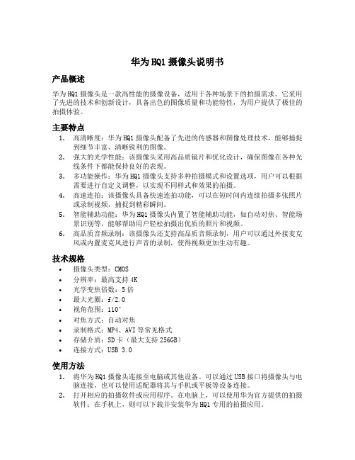
华为HQ1摄像头说明书产品概述华为HQ1摄像头是一款高性能的摄像设备,适用于各种场景下的拍摄需求。
它采用了先进的技术和创新设计,具备出色的图像质量和功能特性,为用户提供了极佳的拍摄体验。
主要特点1.高清晰度:华为HQ1摄像头配备了先进的传感器和图像处理技术,能够捕捉到细节丰富、清晰锐利的图像。
2.强大的光学性能:该摄像头采用高品质镜片和优化设计,确保图像在各种光线条件下都能保持良好的表现。
3.多功能操作:华为HQ1摄像头支持多种拍摄模式和设置选项,用户可以根据需要进行自定义调整,以实现不同样式和效果的拍摄。
4.高速连拍:该摄像头具备快速连拍功能,可以在短时间内连续拍摄多张照片或录制视频,捕捉到精彩瞬间。
5.智能辅助功能:华为HQ1摄像头内置了智能辅助功能,如自动对焦、智能场景识别等,能够帮助用户轻松拍摄出优质的照片和视频。
6.高品质音频录制:该摄像头还支持高品质音频录制,用户可以通过外接麦克风或内置麦克风进行声音的录制,使得视频更加生动有趣。
技术规格•摄像头类型:CMOS•分辨率:最高支持4K•光学变焦倍数:5倍•最大光圈:f/2.0•视角范围:110°•对焦方式:自动对焦•录制格式:MP4、AVI等常见格式•存储介质:SD卡(最大支持256GB)•连接方式:USB 3.0使用方法1.将华为HQ1摄像头连接至电脑或其他设备。
可以通过USB接口将摄像头与电脑连接,也可以使用适配器将其与手机或平板等设备连接。
2.打开相应的拍摄软件或应用程序。
在电脑上,可以使用华为官方提供的拍摄软件;在手机上,则可以下载并安装华为HQ1专用的拍摄应用。
3.根据需要进行拍摄设置。
可以调整拍摄模式、曝光补偿、白平衡等参数,以及选择合适的滤镜效果。
4.对焦并拍摄。
将摄像头对准拍摄对象,通过软件或应用程序进行对焦,并按下快门按钮进行拍摄。
5.查看和编辑照片或视频。
拍摄完成后,可以通过软件或应用程序查看和编辑照片或视频,如裁剪、滤镜处理、音频剪辑等。
HD AVS 摄像头用户手册说明书

HDAVS Camera User’s ManualVersion 1.0.0Table of Contents1General Introduction (1)1.1Overview (1)1.2Features (1)2Device Framework (2)3Installation (7)4Menu (9)4.1HAVR Settings (9)4.2Menu Operation (9)Appendix Ⅰ Maintenance (11)WelcomeThank you for purchasing our HDAVS camera!This user’s manual is designed to be a reference tool for your system.Please read the following safeguard and warnings carefully before you use this series product!Please keep this user’s manual well for future reference!Important Safeguards and Warnings1.Electrical safety•All installation and operation here should conform to your local electrical safety codes.•The power shall conform to the requirement in the SELV (Safety Extra Low Voltage) and the Limited power source is rated DC 12V or AC24V in the IEC60950-1. (Power supply requirement is subject to the device label).•Please install easy-to-use device for power off before installing wiring, which is for emergent power off when necessary.•Please check if the power supply meets the requirements of working voltage of the camera before operating the device (The material and length of the power supply cable will influence terminal voltage value).•Please prevent the line cord from being trampled or pressed, especially the plug, power socket and the junction from the device.2.Environment•Please don’t aim the device at strong light (such as lighting, sunlight and so on) to focus. •Please transport, use and store the device within the range of allowed humidity and temperature. •Please do not allow water and other liquid falling into the camera in case that the internal components are damaged.•Please keep the sound ventilation in case of heat accumulation.•Heavy stress, violent vibration or water splash are not allowed during transportation, storage and installation.•Please pack the device with standard factory packaging or material with same quality when transporting the device.•It is recommended to use the device together with lightning protection device to enhance lightning protection effect.•It is recommended to GND the device to enhance device reliability.•It is advised to use qualified video transmission cable to improve video quality. It is recommended to use 75-3 coaxial cable or higher standard.Warning•Please use the standard accessories provided by manufacturer and make sure the device is installed and fixed by professional engineers.•Please prevent the device surface from the radiation of laser beam when using laser beam device.•Please do not provide two or more power supply modes for the device, otherwise it may cause damage to the device.Statement•Please refer to the actual product for more details; the manual is just for reference.•The manual will be regularly upgraded according to the product update; the upgraded content will be added in the manual without prior announcement.•Please contact the customer service for the latest procedure and supplementary documentation. •The company is not liable for any loss caused by the operation which is not followed by the manual. •Please refer to the company’s final explanation if there is any doubt or dispute.1General Introduction1.1OverviewThis series HDAVS camera conforms to the HDAVS standard. It supports video signal high-speed long distance transmission without any delay. It can be controlled by the HAVR conforming to the HDAVS.1.2Features●Adopt high performance CMOS image sensor, megapixel definition.●Support coaxial transmission of video, audio and control signal.●For 720P series, support 75-3 coaxial cable transmission without any loss. The distance isover 800m. For 1080P series, support 75-3 coaxial cable transmission without any loss.The distance is over 500m.●High speed, long distance real-time transmission.●Support HDAVS HD video and analog video output.●Support 3D noise reduction, excellent low illuminance performance.●Support ICR switch to realize surveillance both in the daytime and at night.●Support OSD menu adjustment parameters.●Support smart IR function.●Support WDR/DWDR function.●Support DC 12V power supply. (Some models support DC 12V/AC 24V power supply).●Support IP67 compliance.●Support IK10 compliance. (Only supported by vandal proof camera)●Can be applied to environments which requires high definition image, such as banking,supermarket, telecom, government, school, airport, factory, hotel, museum and etc.2Device FrameworkSee Figure 2-1 for the dimension of model A.Figure 2-1 See Figure 2-2 for the structure components of model A.Figure 2-2 See Figure 2-3 for the dimension of model B.Figure 2-3See Figure 2-4 for the structure components of model B.Figure 2-4 See Figure 2-5 for the dimension of model C.Figure 2-5 See Figure 2-6 for the structure components of model C.Figure 2-6See Figure 2-7 for the dimension of model D.Figure 2-7 See Figure 2-8 for the structure components of model D.Figure 2-8See Figure 2-9 for the dimension of model E.Figure 2-9 See Figure 2-10 for the structure components of model E.Figure 2-10Note:Mobile models adopt aviation cable; please refer to Figure 2-11 for more details.Figure 2-11See Figure 2-12 for the cable of single channel video output.Figure 2-12Note:There is only one video port for some cameras, which is shown in Figure 2-12, it outputs HD video signal by default, it needs to enable self-adaptation function in the OSD menu to switch to standard definition video signal.See Figure 2-13 for the dual power cable.Figure 2-13Note: Camera models with dual power use the cable structure shown in Figure 2-13; the power input port supports DC12V/AC24V power supply.3InstallationDome camera mainly uses ceiling installation; installation surface includes ceiling and wall. Users can install the device with the installation position map and the screws in the accessories bag.Attention:●Please install the device in time after it is taken apart, which is to avoid the cameramodule being exposed to damp environment for too long.●Before the installation, please make sure the installation surface is thick enough tosustain at least 3X weight of the camera.●For the installation mode of side outlet, make sure the direction of side outlet is inaccordance with that of the installation position map when sticking the installation position map. Besides, pull the cable through the pedestal cable slot before locking the screw.Figure 3-1Note:The installation figure is for reference only.Step 1Take out the installation position map from the accessories bag, and paste it on the ceiling or wall according to the cable exit location, dig holes on the installation surface according to the installation position map, take out the expansion bolts from the accessories bag and insert them into the installation holes and fix them.Step 2Use the wrench to loosen the locking screw in the cover and take down the cover.Step 3Adjust the location of the dome pedestal according to the top cable outlet or side cable outlet. Pull the cable out through the side outlet of installation surface and pedestal (please skip the step if it is top cable outlet), aim the screw fixing holes of dome pedestal to the fixing holes of expansion boles on the installation surface, then insert the self-tapping screws into the expansion bolts and secure them firmly, fix the dome on the installation surface.Step 4Connect the video output port of the device cable to the back-end HAVR device and connect the power port to power.Step 5Lens adjustment●If it is the motorized vari-focal camera, you can adjust the lens zoom and focus on theback-end HAVR device to make image clear, and then adjust the lens angle according to the direction shown in Figure 3-1. Tighten the screws to fix the lens after it is adjusted to a proper angle.●If it is the manual vari-focal camera, you can use focus/zoom lever to adjust lens focallength to make image and tighten the lever after it displays image on the back-end HAVR device, then adjust the lens angle according to the direction shown in Figure 3-1. Tighten the screws to fix the lens after it is adjusted to a proper angle.Step 6Install the dome enclosure; install the enclosure which is taken down in step 2 back to the dome pedestal.So far you have completed device installation and cable connection, you can check device monitoring image via back-end coding device.4Menu4.1HAVR SettingsThis HDAVS camera series can adjust OSD menu via coaxial control. After connected the camera to the HDAVS series HAVR, from Main Menu->Setting->System->PTZ, you need to select the channel number for access and set control mode as HDAVS and the protocol asHD-AVS. Click “Save” button to save current setup. See Figure 4-1.Figure 4-14.2Menu OperationClick the right mouse button and select “PTZ Control”, then you will see the “PTZ Setup” menu, which is as shown in Figure 4-2 and Figure 4-3.Figure 4-2Figure 4-3See Sheet 4-1 for the details of button functions.ButtonFunctionOpen menu 、Select menu item 、 Select menu valueAdjust lens zoom and auto trigger focus Note: Some of the buttons can only be applied for the motorized vari-focal camera.Adjust lens focusAuto focus under current zoom rateLens reset Sheet 4-1If there is “”, click the “Confirm” button in “Menu Operation” interface to go to the 2nd menu. Click “Return” button to go back to the previous menu interface.Appendix Ⅰ MaintenanceAttention:Please maintain the device according to the following instructions in order to ensure the image effect and long-term stable operation of the device.Maintenance for lens and mirror surfaceThe lens and mirror surface are covered with antireflection coating, so it may produce hazardous substance and lead to performance reduction or scratch, dimness etc when it is stained with dust, grease, fingerprint and so on, please refer to the following methods to deal with once dirt is found:Stained with dirtUse oil-free soft brush or hair dries to remove it gently.Stained with grease or fingerprintUse soft cloth to wipe the water drop or oil gently to make it dry, then use oil-free cotton cloth or paper soaked with alcohol or detergent to wipe from the lens center to outward. It is ok to change the cloth and wipe several times if it is not clean enough.Camera Body MaintenanceUse a soft dry cloth to clean the camera body when it is dirty, in case the dirt is hard to remove, use a clean dry cloth soaked with mild detergent and wipe gently, make it dry later. Don’t use volatile solvent like alcohol, benzene, thinner and etc or strong detergent with abrasiveness, otherwise it will damage the surface coating or reduce the working performance of the device.Maintenance for Dome CoverDome cover is an optical device, please don’t touch or wipe cover surface directly during installation and use, please refer to the following methods to deal with once dirt is found:Stained with dirtUse oil-free soft brush or hair dries to remove it gently.Stained with grease or fingerprintUse soft cloth to wipe the water drop or oil gently to make it dry, then use oil-free cotton cloth or paper soaked with alcohol or detergent to wipe from the lens center to outward. It is ok to change the cloth and wipe several times if it is not clean enough.Note•This manual is for reference only. Slight difference may be found in the user interface.•All the designs and software here are subject to change without prior written notice.•All trademarks and registered trademarks mentioned are the properties of their respective owners.•If there is any uncertainty or controversy, please refer to the final explanation of us.•Please visit our website or contact your local service engineer for more information.。
WINMENC0.7
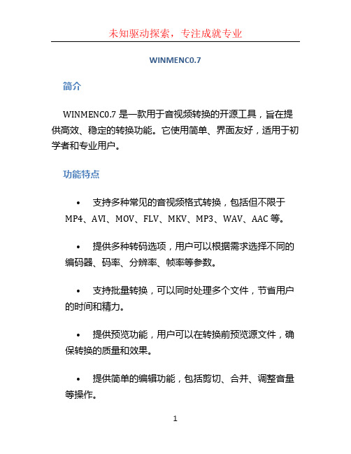
WINMENC0.7简介WINMENC0.7 是一款用于音视频转换的开源工具,旨在提供高效、稳定的转换功能。
它使用简单、界面友好,适用于初学者和专业用户。
功能特点•支持多种常见的音视频格式转换,包括但不限于MP4、AVI、MOV、FLV、MKV、MP3、WAV、AAC 等。
•提供多种转码选项,用户可以根据需求选择不同的编码器、码率、分辨率、帧率等参数。
•支持批量转换,可以同时处理多个文件,节省用户的时间和精力。
•提供预览功能,用户可以在转换前预览源文件,确保转换的质量和效果。
•提供简单的编辑功能,包括剪切、合并、调整音量等操作。
•支持自定义命令行参数,适用于高级用户和脚本自动化。
安装和使用下载安装WINMENC0.7 提供 Windows 平台的安装包,用户只需双击运行安装包,根据提示完成安装即可。
使用方法1.打开 WINMENC0.7 软件,点击界面上的「添加文件」按钮,选择要转换的源文件。
2.在右侧的转码选项中,设置输出文件格式、编码器、码率、分辨率等参数。
3.点击「转换」按钮开始转码,并等待转码完成。
4.转码完成后,可以在软件中预览转码后的文件,检查转换质量是否符合预期。
5.如果需要进一步编辑转码后的文件,可以使用软件提供的编辑功能进行剪切、合并等操作。
6.最后,点击「保存文件」按钮,选择保存目录,并点击「确认」保存转码后的文件。
常见问题解答1.WINMENC0.7 是否免费?是的,WINMENC0.7 是一款开源软件,完全免费使用。
2.WINMENC0.7 是否支持多线程转码?是的,WINMENC0.7 支持多线程转码,可以提升转码速度。
3.是否可以在 WINMENC0.7 中调整音视频的质量?是的,WINMENC0.7 提供了丰富的转码选项,用户可以根据需要自定义编码器、码率等参数来达到所需的质量。
4.WINMENC0.7 能否同时转换多个文件?是的,WINMENC0.7 支持批量转换,用户可以一次性选择多个文件进行转换,节省时间和精力。
软件和驱动版本更新工具的使用方法
软件和驱动版本更新工具的使用方法
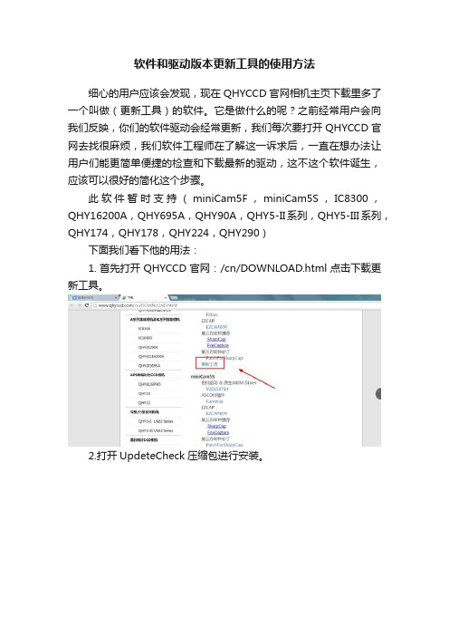
细心的用户应该会发现,现在QHYCCD官网相机主页下载里多了一个叫做(更新工具)的软件。
它是做什么的呢?之前经常用户会向我们反映,你们的软件驱动会经常更新,我们每次要打开QHYCCD官网去找很麻烦,我们软件工程师在了解这一诉求后,一直在想办法让用户们能更简单便捷的检查和下载最新的驱动,这不这个软件诞生,应该可以很好的简化这个步骤。
此软件暂时支持(miniCam5F,miniCam5S,IC8300,QHY16200A,QHY695A,QHY90A,QHY5-II系列,QHY5-III系列,QHY174,QHY178,QHY224,QHY290)
下面我们看下他的用法:
1.首先打开QHYCCD官网:/cn/DOWNLOAD.html点击下载更新工具。
2.打开UpdeteCheck压缩包进行安装。
3.注意要首先要先连接QHYCCD相机,然后打开软件。
4.点击检查更新。
5.看看那些需要更新,点击download
6.直接跳转到相应的下载页面,下载更新相应的软件和驱动就可以了。
[最新]海美迪q系列固件
![[最新]海美迪q系列固件](https://img.taocdn.com/s3/m/857e1b35bdd126fff705cc1755270722182e5959.png)
【海美迪Q系列固件】Q1/Q2/Q4/Q4v2/HD600A安卓版 1.1.2 (2013-2-4)新固件发布[复制链接]ljcamel ljcamel 当前离线威望6018 金钱3296 贡献13228 最后登录2013-2-6注册时间2008-2-18精华6积分17201阅读权限200帖子3677. IP卡狗仔卡181主题0好友1万积分管理员发消息. 电梯直达楼主发表于前天13:25 |只看该作者|倒序浏览【海美迪Q系列固件】Q1/Q2/Q4/Q4v2/HD600A 安卓版 1.1.2 (2013-2-4)新固件发布(2楼更新升级须知)基于1.1.1 版本修改安卓系统平台1)设置中,手动设置Wi-Fi时,密码框自动弹出(更加人性化)。
2)解决了有时候开机无法启动(一直停留在开机画面)或启动后卡住(在首页很难响应操作)的问题。
3)文件管理器中,盘符按照字母的顺序排序(更加人性化)。
4)设置中,指定默认存储设备中的设备名称,用盘符的形式展现(更加人性化)。
媒体兼容性1)多字幕编码的支持(目前基本上支持所有的编码)。
2)屏蔽了播放时,字幕控制符的显示。
3)解决了播放时,有些字幕一闪而过的问题。
4)修改了播放时,默认设置为全屏显示,不加黑边。
5)解决了播放网络视频时,有时候会出现系统的媒体库崩溃的问题。
6)解决了通过网络播放一个不支持的媒体文件时,会出现系统的媒体库崩溃的问题。
7)解决了网络播放seek时,出现播放无响应的问题。
8)解决了网络播放seek时,有时候不成功的问题。
9)对偶尔音视频不同的问题,进行了优化。
海视/HiTV 1.1.1.1. 解决了有时候无法获取数据的问题。
电视直播1)增加了电视回看的新功能。
1.1.2版本,必须从版本1.1.1上升级HD600A固件下载/d/blPOCwK-GwBVQg9R77eQ1固件下载/d/blPOCwITFwA-MA9Ra29Q2固件下载/d/blPOCwJAFwDfMA9R68cQ4固件下载/d/blPOCwKUFwAZMg9R0ccQ4v2固件下载/d/blPOCwLZFwBBMw9Rd5d(下载链接,会随着下载次数越多而变得越快)Q系列盒子升级须知/forum.php?mod=viewthread&tid=58460HiControl(海控手机端),HiShare(海享手机端)手机下载地址相关介绍/forum ... &extra=page%3D1Q系列盒子升级须知1)Q5、Q2、Q4、Q4v2 HD600A升级文件分别独立,不能相互升级2) 特别提醒Q4 和Q4v2是不同的固件文件,两个产品型号通过产品的机身可以看到。
- 1、下载文档前请自行甄别文档内容的完整性,平台不提供额外的编辑、内容补充、找答案等附加服务。
- 2、"仅部分预览"的文档,不可在线预览部分如存在完整性等问题,可反馈申请退款(可完整预览的文档不适用该条件!)。
- 3、如文档侵犯您的权益,请联系客服反馈,我们会尽快为您处理(人工客服工作时间:9:00-18:30)。
■经参
一辆混凝土罐车转弯时,地面突然塌陷,罐车四个车轮陷入塌陷处后倾倒,砸中路边两辆车;一幢只有20年历史的居民楼突遭粉碎性倒塌,事故造成一人死亡、六人受伤……近年来,随着地下渗水导致楼倒路陷等建筑安全事件的频发,一度被人忽视的建筑地下渗漏问题正愈发引起公众的关注。
而据中国建筑防水协会和北京零点市场调查与分析公司联合发布的《2013年全国建筑渗漏状况调查项目报告》,全国建筑地下渗漏率达到57.51%,个别城市渗透率甚至达到百分之百,我国建筑地下渗漏的现状不容乐观。
楼倒地陷事故累累
近年来频频发生的地面塌陷、楼房倾斜倒塌事件,在很大程度上,与建筑地下长期渗漏有重要关联。
2014年9月,北京市大兴区西红门南桥附近,一辆混凝土罐车转弯时,地面突然塌陷,罐车四个车轮陷入塌陷处后倾倒,砸中路边两辆车,幸无人员伤亡。
据现场工人介绍,该处由于绿化带内电信井渗水,渗入路床内导致基层泥土被涮空,路面下出现一直径约2米的空洞,造成最后的塌陷。
另据公开报道,2014年4月4日,浙江奉化一幢只有20年历史的居民楼突遭粉碎性倒塌,事故造成一人死亡、六人受伤,伤者中一名年轻的女孩惨遭截肢。
此前,倒塌的楼房曾获评样板工程。
事件发生后,技术人员对周边7幢房屋进行质量检测。
在挖开地基时,其中两处仅下挖半米深即冒出大量地下水,工作人员用一台抽水机持续作业都无法抽光。
事后专家分析认为,事故发生原因在于地下防水工程不合格,导致地下长期渗漏,进而引发钢筋锈蚀、混凝土劣化、建筑地下结构形态发生改变等一系列问题。
数据显示,我国每年新增大约20亿平方米的建筑总量,超过全球年建筑总量50%以上,是每年新建建筑量最大的国家,然而这些建筑的寿命却很少能达到设计年限。
“影响建筑寿命的因素很多,包括城市规划的原因,但其中肯定有地下渗漏的问题,如此大的建筑体量,如果不能把好建筑安全这一关,将埋下重大的安全隐患。
”全国政协常委、九三学社中央副主席赖明如是表示。
地下结构存在先天缺陷
结构主体防水没做好,附着在上面的防水层做得再好,也无法避免地下渗漏问题,因为再好的防水材料也不可能保障建筑设计寿命。
记者走访北京及周边多个正在施工的工程项目,在问及现场施工人员该建筑是否做防水处理时,多数项目负责人表示已经做过,有的项目负责人还向记者强调,他们的工程用的是市面上最好的防水材料。
业内防水专家、北京龙阳伟业科技有限公司董事长王伟表示,目前人们对于建筑地下防水的认识走入误区,忽视了结构自防水的主导作用。
地下渗漏在于地下结构存有“先天缺陷”,另外,随着时间推移,有害物质将借助于渗漏水,对本就存在隐患的建筑地下结构造成“后天伤害”,最终将会缩短建筑寿命,也会直接威胁建筑安全。
“结构主体防水没做好,附着在上面的防水层做得再好,也无法避免地下渗漏问题,因为再好的防水材料也不可能保障建筑设计寿命。
”
北京市政府专业顾问、2008奥运工程指挥部领衔专家杨嗣信教授指出,目前建筑地下防水过分依赖“防水材料”的思想已成惯性,造成建筑地下结构的许多问题被忽视和遮蔽,而地下结构设计和管理上的缺陷,是任何防水材料都无法弥补的,“防水材料”不过是建筑结构问题的遮羞布。
事实上,地下工程的混凝土不仅要具有结构功能和安全,同时也要有防水密实的功能。
然而当前我国“结构问题”被忽视,将大量精力专注于地下工程的“材料防水层”,而防水材料寿命也不过只有二三十年,与建筑百年寿命的预期相差甚远。
而按目前相关标准,建筑地下防水保修期仅5年。
建筑地下防水与建筑寿命不匹配的矛盾突出,直接影响建筑安全。
防水工程成摆设
一些地方开发商有个特点,在建筑工程上重造型、重外表,而不重视内在质量好不好,这种思维直接导致在工程中装修的价钱提得很高,而地下工程费用却捉襟见肘。
北京城建科技促进会常务副理事长王建明在接受记者采访时表示,现在在施工过程中,很多人简单凑合地把防水做完,费用压得很低,漏了再堵。
另外,还有一种现象,施工方觉得反正是漏水,干脆就不做防水,漏了以后再去堵、再去修。
实际上大家只是把防水作为功能问题,没有把防水的渗漏问题上升到影响质量安全的高度。
王伟认为,要解决我国地下工程安全问题,首先需要改变的是观念。
“人们过度追求速度、追求利润,不可避免地降低建筑质量标准,忽视建筑质量与建筑安全。
特别是对建筑地下结构隐蔽性工程问题进行遮盖或隐藏的思维方式以及急功近利、忽视质量的价值取向,是导致我国建筑质量普遍较差、建筑寿命过短、建筑安全隐患日益严重的根本原因。
”地下渗漏后患无穷
据统计,我国目前现有400亿平方米的既有建筑,每年新增总量约20亿平方米。
但同时,我国建筑地下渗漏现象与日俱增,“三高现象”凸显。
防水材料生产和施工技术水平越
来越高,建筑地下防水验收合格率越来越高,而建筑地下渗漏率却越来越高,“三高痼疾”长期困扰我国建筑业质量水平的提高,建筑地下渗漏严重影响建筑寿命,威胁建筑安全。
王伟表示,造成这种困境的原因是当前我国大量应用于地下工程防水的“防水层”,其材料寿命最多不过20余年,应用在工程中,实际寿命更短,与建筑百年寿命的预期相差甚远。
按相关标准,建筑地下防水工程保修期仅5年,与建筑结构寿命不匹配的矛盾十分突出。
王伟指出,防水行业是建筑业最底层最末端的一环,处在被忽视、漠视的边缘。
正因如此,近年楼价翻番,装修的投入也在不断增加,但建筑防水造价却在低位运行,行业内偷工减料、以次充好的现象大行其道。
“更可怕的是,现在没人重视建筑地下渗漏对建筑安全的危害,如果当前不解决这一问题,未来会埋下很大的安全隐患。
”
/u/5536011327 /u/5536011570 /u/5535555814。