5082-A513-HL300中文资料
(产品管理)传统三辊闸机产品说明

最新卓越管理方案您可自由编辑翼闸使用说明书深圳市嘉讯通电脑技术有限公司地址:深圳市宝安区龙华镇民治大道横岭工业区10栋电话:86-755-29838917 传真:86-755-29838609 网址:E-mail:www.jiaxuntong@目录基本参数 (1)机芯 (1)驱动板 (2)用户接口 (2)联网接口 (3)其他接口 (3)调试与安装 (3)调试 (3)安装 (4)常见问题处理 (4)基本参数箱体尺寸: 1400*300*1000MM 通 道 宽:≤600MM电源电压:AC220±10%V ,50HZ 工作温度:-30度~60度 工作湿度:≤90%,不凝露输入接口:a.12V 电平信号或>10ms 的12V 脉冲信号; b.驱动电流>10mA ; 闸门开、关时间:0.7秒机芯电磁铁电机轴承座1轴承座2齿轮组离合机构限位块翼主轴上位接近开关下位接近开关轴承座3翼闸机芯由电机、齿轮组、离合机构、上位接近开关、下位接近开关、电磁铁、限位块、驱动板等组成。
上图为主要的机械结构,其工作原理为:翼闸静止时,翼处于关闭状态,当驱动板接收到有效开闸信号,电机开始转动,经齿轮组减速后,主轴转动。
当转动到极限位置时,上位接近开关接收到信号,电机断电,电磁铁收缩,限位块与其下方的弹性材料接触并逐渐缓冲,在很短的时间内主轴停止转动。
当第二对红外线检测到行人通过信号时,电机开始反转,电磁铁复位。
转动到这个方向的极限位置时,下位接近开关检测到信号,电机断电,限位块与其下方的弹性材料接触并逐渐缓冲,在很短的时间内主轴停止转动。
安装在箱体内侧面的三对红外线的作用如下: (1) 第一对红外(进方向或出方向):用于检测行人是否已经合法进入通道区域。
如果是非法进入,翼闸开始报警。
注:报警的前提是门禁或其他控制板有报警信号输出给翼闸驱动板。
(2) 第二对红外:一旦检测到行人通过,翼开始关闭(3) 第三对红外:检测行人是否完全通过翼闸,如果在第二、三对区域内停留的时间超出默认值,系统报警。
RF300系列电流闭环矢量型变频器说明书
17.0
16
21.0
20
RF300-7R5G-2
7.5
范围:
RF300-011G-2
11.0
31.0
30
43.0
42
适配电机
0.4 0.75 1.5 2.2 0.75 1.5 2.2 4.0 5.5 7.5 11.0
3
变频器型号
RF300-015G-2 RF300-018G-2 RF300-022G-2 RF300-030G-2 RF300-037G-2 RF300-045G-2 RF300-R75G-4 RF300-1R5G-4 RF300-2R2G-4 RF300-4R0G/5R5P-4 RF300-5R5G/7R5P-4 RF300-7R5G/011P-4 RF300-011G/015P-4 RF300-015G/018P-4 RF300-018G/022P-4 RF300-022G/030P-4 RF300-030G/037P-4 RF300-037G/045P-4 RF300-045G/055P-4 RF300-055G/075P-4 RF300-075G/090P-4 RF300-090G/110P-4 RF300-110G/132P-4 RF300-132G/160P-4 RF300-160G/185P-4 RF300-185G/200P-4 RF300-200G/220P-4 RF300-220G/250P-4 RF300-250G/280P-4 RF300-280G/315P-4 RF300-315G/350P-4
460/500
470/520
500/580
520/600
580/620
600/640
适配电机
15.0 18.5 22.0 30.0 37.0 45.0 0.75 1.5 2.2 4.0/5.5 5.5/7.5 7.5/11.0 11.0/15.0 15.0/18.5 18.5/22.0 22.0/30.0 30.0/37.0 37.0/45.0 45.0/55.0 55.0/75.0 75.0/90.0 90.0/110.0 110.0/132.0 132.0/160.0 160.0/185.0 185.0/200.0 200.0/220.0 220.0/250.0 250.0/280.0 280.0/315.0 315.0/350.0
塑料型号性能表

品名牌号产地熔融指数用途吹塑中空级,主要用于大容器和工业容器,如HDPE5200B大庆石化0.2-0.5化学品、汽油桶、大玩具等。
注塑级,抗冲击和刚性高,主要用于周转箱(水HDPE2200J大庆石化 3.5~7.5果、食品、啤酒),工业部件、瓶等挤出级.挤出成型、适用机械强度高的绳索和阀HDPE5000S大庆石化0.9用单丝。
挤出.可用于绳索和网用单丝,而且可用于中空HDPE5301AA独山子0.08制品、管材等。
HDPE6070独山子石化 6.5-9.0薄膜级,包装使用购物袋,薄壁袋等HDPE2911抚顺乙烯20注塑级注塑级.家俱、一般容器、薄壁容器、周转箱、HDPE2908抚顺乙烯8托盘、体育设施、安全帽、鱼箱注塑级.家俱、一般容器、薄壁容器、周转箱、HDPE5000S兰州石化0.8-1.2托盘、体育设施、安全帽、鱼箱挤出.可用于绳索和网用单丝,而且可用于中空HDPE5070盘锦乙烯 6.1-8.0制品、管材等。
HDPE5010盘锦乙烯0.6-1.0注塑级.鱼箱、板条箱、手提箱。
HDPE6098齐鲁石化9.0~14.0拉丝级.生产单丝、扁丝、制鱼网、绳等。
薄膜级,良好的耐热性和耐寒性。
生产购物袋、HDPE5502上海金菲0.25-0.45杂货袋、多层衬里膜、耐候膜等HDPE TR144上海金菲0.16-0.22产品袋、垃圾袋、多层复合袋、购物袋。
HDPE TR550上海金菲2HDPE TR480上海金菲0.08~0.14燃烧气,上水管,工程管。
HDPE50100上海金菲7.5-11.0200升桶、油箱、托板、大型部件、游艇。
洗涤剂、化妆品瓶;工业化学品容器;电动机HDPE5502AA上海赛科0.2润滑油瓶。
HDPE5301AA上海赛科0.08薄膜级.包装使用购物袋,薄壁袋等吹塑大到30升、用来盛装如食品、油和化学HDPE MH602上海石化0.2品的容器HDPE CH2802上海石化0.4薄膜级.工业用衬垫、重包装袋和购物袋。
300MW汽轮机说明书

前言哈尔滨汽轮机厂制造的N300-16.7/537/537型汽轮机,是以美国西屋公司的30万千瓦考核机组的技术为基础,通流部分等经过合理的设计改进后的一台新型汽轮机,它保留了30万千瓦考核机组的技术特点,又通过通流部分的优化设计,使其可靠性和经济性有较大的提高。
本说明书仅适用于哈尔滨汽轮机厂优化设计并制造的30万千瓦汽轮机的启动、运行和维护,而对于机组在安装后的初始启动,只供参考。
特别是机组在非正常工况时,必须以运行人员的实践经验和正确判断,决定是否有必要采取特殊的措施。
本书中第三部分“控制方式”的编写,是以西屋公司DEH MOD Ⅱ型装置为基准,不一定与用户实际选用配置的设备相同,故只供参考。
特别指出机组在最初六个月的运行期间,汽轮机应采用单阀控制方式。
1、汽轮机监视仪表30万千瓦汽轮机装有本书所列的各类监视仪表,用来观察机组的启动、运行和停机状况。
这些监视仪表的输出量,图标记录仪进行记录。
1.1汽缸膨胀测量仪当机组从冷态进入升温和带负荷状态时,温度的变化必然导致汽缸的膨胀。
汽缸膨胀测量仪用来测量汽缸从低压缸死点向前轴承箱方向的轴向膨胀量,前轴承箱沿着加润滑剂的纵向键可以自由移动。
当汽缸膨胀时,如果机组的自由端在倒键上的滑动受阻,则会造成机组的严重损坏。
汽缸膨胀测量仪实际上是测定前轴承箱相对死点(基础)的移动量,并记录当机组起、停和负荷、蒸汽温度变化时汽缸的膨胀量和收缩量。
在这些瞬时工况下如果指示值出现异常现象,则运行人员应当对它加以分析。
在负荷、蒸汽参数和真空相似的情况下,这种仪表所指示的前轴承箱的相对位置,应该基本上是相同的。
汽缸膨胀没有报警和跳闸限制值。
仪表指示的汽缸膨胀值应和以前在同样运行工况下的读数进行比较,若两者存在较大差异,运行人员就应该作出判断,通常可采用在低压缸撑脚,轴承箱底座与台板接触面上加润滑脂改善润滑的方法来加以处理,有时候也需要调整轴承⒉座,使之膨胀顺畅。
1.2转子位置测量汽轮机装有两个转子位置测量仪,以测量转子的推力盘相对于轴承座的轴向位置,由于蒸汽的作用,推力盘对位于其两侧的推力瓦块施加轴向压力,由此引起的轴瓦磨损使转子轴向移动将在转子位置测量仪上显示出来。
福建澳泰自动化设备 AO 5082 热电阻输入隔离安全栅 说明书
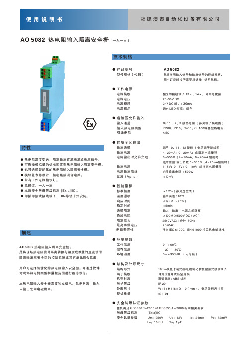
特性● 热电阻温度变送,隔离输出直流电流或电压信号。
● 可选择模拟量的标准固定型热电阻输入隔离安全栅。
● 也可选择智能化的热电阻输入隔离安全栅。
● 模块化表芯设计,精密集成混合电路。
● 带有工作电源指示灯。
● 单通道,一入一出。
● 本质安全防爆等级标志 [Exia]IIC 。
● 即插即拔式接线端子,DIN导轨卡式安装。
描述技术规格● 产品型号 AO 5082型号规格(代码) 代码指明输入信号和输出信号的详细规格, 用户订货时按所需要求选择 , 标明代码 。
● 工作电源电源接线 独立的接线端子 13-、14+,可带电拔插 电源电压 20~30V DC电流损耗 24V DC 时,< 30mA 电源指示 通电 LED 灯亮:绿色● 危险区允许输入输入通道 端子 1、 2、3 接热电阻 (参见端子接线图) 输入热电阻类型 Pt100;Pt10;Cu50;Cu100等各型热电阻 引线电阻 ≤5Ω● 向安全区输出输出通道 端子 10、11、12 接线 (参见端子接线图) 输出电流 4~20mA;0~20mA;或指定电流量程 电流输出时允许负载 0~550Ω(4~20mA,0~20mA 输出时)选智能型: 输出负载 0~350Ω(4~20mA输出时) 输出电压 1~5V;0~5V;0~10V;或指定电压量程 电压输出阻抗 内置输出电阻 <500Ω 纹波(Vp-p) <10mV● 性能指标标准精度 ±0.2% 温度漂移 响应时间 ≤1s(0 → 90%) 稳定时间 <5 min通道隔离 输入-输出-电源之间隔离 绝缘电阻 ≥100MΩ/500V DC(AC) 隔离能力 2500VAC/1 分钟 50Hz 最高防爆电压 250VAC电磁兼容性 符合 IEC 61000,EN 61000 相关抗电磁标准● 环境参数工作温度 0~+60℃ 储存温度 -20~+80℃环境湿度 5~+95%RH (无冷凝)● 结构及外形尺寸结构形式 16mm厚度,卡装式结构,模块化表芯,拔插式接线端子 端子接线 自升压簧片式压紧连接 机壳材质 聚碳酸脂 / ABS 材料 防护等级 IP 20外形尺寸 W 16×H116×D110(mm),参见外形尺寸图 整机重量 约110g● 安全防爆认证参数整机满足 GB3836.1-2000 和 GB3836.4-2000 标准相关要求 防爆等级标志 [Exia]IIC安全认证参数 Um:250V Uo:12V Io:24mA Po:72mWLo:10 mH Co:1μF(参见选型表)基本误差 / 10℃AO 5082 热电阻输入隔离安全栅(一入一出)AO 5082 热电阻输入隔离安全栅。
国内外塑料模具钢牌号对照表

耐蚀镜面塑料模具钢,奥地利Bohler(百禄)公司的厂家牌号。
M310ESR
M310HESR
预硬化镜面塑料模具钢,奥地利Bohler(百禄)公司的厂家牌号。
M340
ISOPLAST
高级耐蚀镜面塑料模具钢,奥地利Bohler(百禄)公司新上市的厂家牌号。
附表1
牌号
说明
NAK55/
NAK80
45WCrV7
45WCrV8
2710
5XB2C
Cr12MoV
——
——
STD11
X165CrMoV12
——
2310
X12M
Cr12MO1V1
D2
SKD11
——
X155CrMoV12-1
X160CrMoV12
——
——
9Mn2V
O2
——
——
90MnCrV8
90MnV8
——
9T2
国内外塑料模具钢牌号对照表
中国
Y7
T7A
——
——
——
C70W1
C70E2U
——
Y7A
1.带*号的钢材为该国某些厂家牌号。(见附表1)
2.以下材料为部分国家的厂家牌号:
附表1
牌号
说明
CLC2083
耐蚀镜面塑料模具钢,法国USINOR(于其诺尔)公司的厂家牌号。
CLC2316H
CLC2738HH
高级镜面塑料模具钢,法国USINOR公司的厂家牌号。
镜面塑料模具钢,日本大同特殊钢(株)的厂家牌号。
PXZ
预硬化塑料模具钢,日本大同特殊钢(株)的厂家牌号。
S-136
耐蚀塑料模具钢,瑞典ASSAB(一百胜)厂家牌号。
PP牌号与熔指大全(PP牌号下)讲解

PP牌号与熔指大全(PP牌号下)讲解PP-纤维类型号产地熔指g/10min特性及用途T30S 西太/有机抚顺/天津华北/大庆齐鲁/青岛茂名/兰化2.5-3.5用于膜丝、纺织膜丝线、地毯背衬T30S辽宁华锦3.2编制带丝,用于包装,地毯背衬,人工草坪,捆扎绳,包装绳及其他应用C30S辽宁华锦6流延膜生产工艺生产的编织带丝,捆扎绳,绳,单丝用于刷子和扫帚,针织土工布F401盘锦/兰港 2.5-3用于编织袋、打包带,及一些小制品PP022有机/前郭3用于膜丝、纺织膜丝线及地毯背衬S1003燕山/赛科/独山子3.2用于窄带、扁丝5004辽阳石化 2.6-4.4适用于切制薄膜(扁丝)、单丝、复丝HP550J中海壳牌3.2曾用名T30S;可用于拉丝、纤维及注塑成型F501韩国晓星兰化/兰港3用于编织袋、包装用绳,作业安全性H0305G印度信诚3用于编织袋、包装用绳H5300韩国湖南3.5用于包装袋、绳子5014大韩油化 3.5用于编织袋、包装用绳S30S辽宁华锦1.8编制带丝,流延膜或管膜生产工艺,用于包装,工业纤维,捆扎绳、包装绳、单丝应用Y-130韩国湖南 3.5纱纤维级、平纱级,高韧性、高伸张率;用于包装袋、捆扎带、纤维纱、草坪等6531M马来大腾2用于绳、带、纺织袋H730F韩国SK 3.5用于绳、带、纺织袋、防水布SY130韩国湖南 3.5高韧性、高伸长率;用于包装带、捆扎带H430韩国LG 3.5用于膜丝、编织膜丝线及地毯背衬等3365美国3高韧性、高伸长率;用于包装带、捆扎带HP450J韩国大林3用于膜丝、编织膜丝线及地毯背衬等HP502N中海壳牌12曾用名F30S,用于纤维、地毯等HP550R中海壳牌25曾用名Z30S,用于纤维、连续纤维、非连续纤维等Z30S大连西太22-27低速纺短纤维,用于BCF-CF复丝Z30S大连有机11-20纺丝类Z30S华北一炼25适用于中速到高速纺生产的细旦膨化丝,连续丝、长丝Z30S抚顺乙烯20均聚物,用于长丝、丙纶、丙纶短纤维.Z30S 新彊独山子22-28均聚物,用于长丝、丙纶、丙纶短纤维.Z30S辽宁华锦25低旦尼尔BCF、CF和短纤,中高纺速生产线上生产的BCF丝用于地毯,CF丝用于捆扎绳,扶手,包装等Z21S辽宁华锦25用于高速生产线生产的窄份资料分布牌号,低旦尼尔,纺粘型无纺布,用于尿布,医用卫生品,也可用于优质纱和BCF丝。
笼式双座调节阀-KHCB笼式双座调节阀
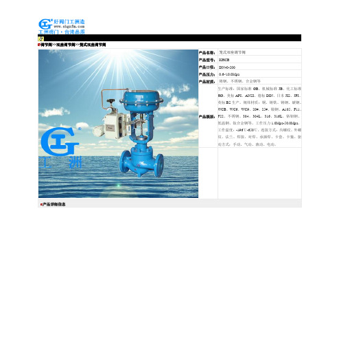
调节阀>>双座调节阀>>笼式双座调节阀产品详细信息调节阀系列价格供用户或设计院工程项目做预算一、阀门的选型步骤1.明确阀门在设备或装置中的用途,确定阀门的工作条件:适用介质、工作压力、工作温度等等。
2.确定与阀门连接管道的公称通径和连接方式:法兰、螺纹、焊接等。
3.确定操作阀门的方式:手动、电动、电磁、气动或液动、电气联动或电液联动等。
4.根据管线输送的介质、工作压力、工作温度确定所选阀门的壳体和内件的材料:灰铸铁、可锻铸铁、球墨铸铁、碳素钢、合金钢、不锈耐酸钢、铜合金等。
5.确定阀门的型式:闸阀、截止阀、球阀、蝶阀、节流阀、安全阀、减压阀、蒸汽疏水阀、等。
6.确定阀门的参数:对于自动阀门,根据不同需要先确定允许流阻、排放能力、背压等,再确定管道的公称通径和阀座孔的直径。
7.确定所选用阀门的几何参数:结构长度、法兰连接形式及尺寸、开启和关闭后阀门高度方向的尺寸、连接的螺栓孔尺寸和数量、整个阀门外型尺寸等。
8.利用现有的资料:阀门产品目录、阀门产品样本等选型适当的阀门产品。
二、阀门的选型依据1.所选用阀门的用途、使用工况条件和操纵控制方式。
2.工作介质的性质:工作压力、工作温度、腐蚀性能,是否含有固体颗粒,介质是否有毒,是否是易燃、易爆介质,介质的黏度等等。
3.对阀门流体特性的要求:流阻、排放能力、流量特性、密封等级等等。
4.安装尺寸和外形尺寸要求:公称通径、与管道的连接方式和连接尺寸、外形尺寸或重量限制等。
⑤对阀门产品的可靠性、使用寿命和电动装置的防爆性能等的附加要求。
(在选定参数时应注意:如果阀门要用于控制目的,必须确定如下额外参数:操作方法、最大和最小流量要求、正常流动的压力降、关闭时的压力降、阀门的最大和最小进口压力。
)根据上述选型阀门的依据和步骤,合理、正确地选型阀门时还必须对各种类型阀门的内部结构进行详细了解,以便能对优先选用的阀门做出正确的抉择。
管道的最终控制是阀门。
gh300 数据手册说明书
3 电源管理和复位 ..................................................................................................................................................... 6 3.1 芯片上电时序................................................................................................................................................. 6 3.2 复位................................................................................................................................................................. 6
合康HID300A通用变频调速器使用说明书

3 操作 .........................................................................................................25 3.1 操作键盘说明 ...........................................................................................25
安全说明 ..........................................................................A 快速安装指南....................................................................B 详细使用说明....................................................................C
UL 508认证标准(中文版)

UL508P83-100设备性能42综述42.1工业控制设备的性能应该通过按照43-61B 节中所描述的试验项目对典型样品或商业贸易中的样品进行试验来验证并要求那些测试按照表42.1所示的操作顺序进行42.2那些导致某一测试项目终止的温度或电流敏感设备或系统应该进行附加的评估测试来确定他们适用于其应用场合42.3除非特别说明测试应采用表42.2中所指定的实际使用电压的额定频率42.4除非特别说明测试应在10-4050-104℉的任意环境温度下进行环境温度的测量应采用在设备的附近安装温度计或热电偶的方法测量42.5对于有不完全封闭或局部外壳的工业控制设备将在本标准中被作为一个开放式无外壳设备来考虑其性能要求表42.1测试顺序样品数量 注1 2 标准参考条款试验项目 顺序 顺序 43 44 45 46 49温升测试过电压和欠电压测试 过负载测试 耐久性测试 介质耐压测试1 2 31 2 3注所有或任一个试验顺序的分组取决于单一样品是否适用任何一个试验顺序没有必要作为进行其他试验项目的首要条件表42.2测试电压值设备的额定电压试验项目110-120 220-240 254-277 380-415 440-480 560-600标准条款编号温升测试 120 240 277 415 480 600 43 过电压试验 AC / DC 132 264 305 457 528 660 44 欠电压试验AC 102 204 235 353 408 510 44 欠电压试验DC96 192 222 332 384 480 44过负载 120 240 277 415 480 600 45 耐久性 120 240 277 415 480 600 46a如果设备的额定值不落在表中的任何电压值范围内除了过压测试和欠压测试见43.8外都以设备的额定电压值作为他的测试值42.6敞开式设备应安装在一个被认为是预期典型使用的罩壳内最大罩壳尺寸可以通过以下任一方法来确定a设备长宽高三尺寸的150%b尺寸符合表6.8所列的导线弯曲空间c预期的罩壳如一标准出路盒子或d预期的罩壳假如标注在设备或卡片上的尺寸可以比42.6a-42.6c所确定的尺寸大例外如36.7a所指定继电器的不必要这样测试 [注36.7a额定功率为1马力输出功率746瓦或相当的FLA或者更小的720伏安断开控制器功率或更小或电压为51-150伏时电流不大于15安培电压为151-300伏时电流不大于10安培或电压为301-600伏时电流不大于5安培]42.7为了进行测试将有两个或更多开-关位置的换向控制器切换开关仪表开关双回路或三回路装置或其他类型的装置进行连接以便使正常使用中会出现的相反极性施加于断开触点或零件之间参见64.1 [注64.1导线接线端应明确标识导线连接的适当的电源负载控制回路等类似的或者一配线表代码以确保能够安全连接设备例外1至于一双接线端开关装置导线连接是非常明白的接线端不必标识例外2在安装配线表说明书后如数目方面可以独立的提供具有多样回路安装的配线表或者在一封袋上提供名牌或类似永久的显著的附件例外3对于一开放式设备配线表可以与设备分开提供]例外明确标识有极性的设备应按标识所指的极性进行连接42.8在测试期间设备应是处于约定的正常连接和安装状态以体现正常使用状态除了体现终端扭矩测试59节所有导线终端模块或导线连接器接线端子应按照产品注明的扭矩力值紧固43温度测试43.1在43.2-43.27描述的条件下进行测试工业控制设备应满足以下要求a不达到对设备上所采用的材料构成着火危险或不利影响的高温b不能超过设备中任何一个零部件的极限温度以及c在特定测试点不能超过表43.1描述的温升值43.2在表43.1所列的所有温升值适用于约定最高允许环境温度为40的设备43.3 43.3和43.5合并和重新修订43.4 删除43.5 43.3和43.5合并和重新修订43.6 假如工业控制设备约定最高允许环境温度高于40则在这更高环境温度下允许的温升按照如下计算公式计算TR = TT- [TM- 40]其中T R 允许的温升值T T 表43.1所允许的最大温度升高TM设备上所标识的更高环境温度见62.1.1 [注设备应该服役在规定的额定的40的温度条件下或高于或低于40并且以5的整数倍为间隔如45505560]43.7 假如工业控制设备约定最高允许环境温度低于40则在这较低环境温度下允许的温升按照如下计算公式计算T R = T T + 40 - T M其中T R允许的温升值T T 表43.1所允许的最大温度升高T M设备上所标识的较低环境温度见62.1.143.8测试时线圈电压应按照表42.2所列然而当制造厂商提供了在表42.2所列每一指定电压范围内如110115或120伏特的不同额定电压变压器或电磁铁线圈以及如果线圈是采用每一额定范围内的最大值激励则应该对每一电压范围内的典型线圈规格按照44.1条明确的百分比确定试验电压进行测试如果线圈没有提供在每一范围内的最大电压等级测试应控制在表42.2所列的所有线圈测试电压43.9为了确定工业控制设备是否达到温度测试的要求应该按照以下条件进行操作a 在正常条件下b 连续通以额定电流见43.1-43.13条c 给线圈施加如表42.2或43.8条所规定的电压例外除了线圈额定电压以外的低压电源可以代替规定的电压值用于零部件的温度测试 d 约定的安装方式见43.14和43.16条e 在43.17条所规定的环境温度下f需要达到温度稳定见43.25条在测试的结果方面每一种材料或部件的温升不能超过在43.143.6和43.7条中所列的最大温升值一种材料或部件的温升是其稳定时温度与测试环境温度之间的差值在测试过程中保护装置或线路不应动作对于按照43.17条a测试的具有温控装置或其他热保护装置的设备这些温度装置的动作温度应该予以测量并修正环境温度的差值通过将修正后的温度值与保护装置动作温度比较以确定是否该设备发生温度保护并将其作为测试的结果43.10由于某一部件的发热可能会影响到其他部件的发热所以应该在所有部件同时工作时进行温度的测量43.11设备额定马力所对应的额定电流如表45.245.362.2或62.3所示表43.1最大温升 材料和部件℉1 闸刀开关的刀片和接触口 30 542 当用虚拟保险丝模拟一个用于保护支路回路的保险丝测试的保险丝夹子 30 54 3当用为了保护支路回路的测试的保险丝夹子o85 1534 橡胶或热塑形绝缘材料 aa5接线端配线区域c,k,i设备标识为60或60/75的应用导线设备标识为75的应用导线5065901176总线和接线板或接线棒d 7 触点纯以及复合银银合金以及镀银其他所有材料e65e1178 绝缘系统105级绝缘系统 f热电偶法电阻法105A级绝缘系统用于单层series非绝缘或上漆裸露线圈热电偶法120E级绝缘系统f r热电偶法电阻法130B级绝缘系统f r热电偶法电阻法155F级绝缘系统f r热电偶法电阻法180H级绝缘系统f r热电偶法电阻法200N级绝缘系统f r热电偶法电阻法220R级绝缘系统f r热电偶法电阻法658590759585105951151151351351551551751171261621351711531891712072072432432792793159 绝缘材料 b p p10 在流动空气环境下距离设备外壳1英尺25.4mm处 175175 11 固定电阻和可变电阻的包裹材料内含阻性元器件的墙面安装型调光器 300 54012 已经内置阻性导体并用于安装在配电盘或不可燃的框架内的变阻调光350 630器的包裹材料67513 裸露的电阻材料热电偶法 375g14 电容 g15 功率切换半导体器件 mmn16 印刷线路板 nq17 1-16项中没有规定的材料和部件 qa 对于绝缘导体最大温升不能超过规定的导线所讨论的减去一个假定的室内温度40的最大工作温度b对于已经调查过的特殊的额定温度的复合最大温升不能超过额定温度减去假定的环境温度40c配线接线端或接线片的最有可能被接触点的温度的测量通过绝缘导体作为实际服务安装d界限不能用于连接热源如电阻器和一过载继电器的电流元件e通过相临部分材料的温度界限的温度极点见43.18不能有接触装配结构变化部件的松开破裂或材料的剥落簧片韧度降低部件的退火或其他明显的损伤f见43.19-43.25g对于一电容器最大温升是电容标识限定温度减去40h删除i当升高值是50或低于打算用一个铝才连接器或铝导线连接器应按AL7CU或AL9CU标识当接线端温升在50-65之间时连接器的标识应为AL9CUj删除k见63.3l极限值仅仅是用于线路板bus bars和用于工业控制装置功率分分布的接线板极限值不应用于位于工业控制装置短片的铜板和用于固定接触单元或工厂或配线区终端这种结构类型的最大温升取决于所用材料的的温度限定值材料的临近部分或者在铜材表面最低的温升100他们不能有装配结构的恶化部件的松散开裂或材料的剥落簧片韧度的降低部件的退火或其他明显的损伤m在这种条件下的最大温升是这种最大条件下温度应用于被半导体制造商推荐的功率消耗减去40n印刷线路板的最大温升是线路板的工作温度减去40o见63.23p见表15.2和37.1q任何组件的最大温升不能超过组件的极限温度减去40r绝缘系统应该符合UL1446绝缘材料系统标准综述的要求43.12对于电流特性表中具有最小和最大满负载电机电流的设备温度测试应采用表中所列的最大满负载电流进行即使这个电流超过了设备的最大额定电流对于电流特性表中只是稳态tripping电流的设备测试电流应采用所规定的最大稳态电流的87%43.13对于直接安装在接触器或启动器上的一个辅助开关测试电流应符合与额定切换电流相一致的最大分断电流43.14工业控制设备的测试应采用1.2m长的导线来连接每一接线端比如当导体是连接在两个接线端子之间则需要用2.4m长的导线导线的最小允许规格应至少能够承受以下负载的125%a与表45.2或45.3相一致的最大满载电机电流适当的至少对于其他负载的100%b对于如表43.1所列具有最高额定电流特性应用了可更换电流元件的过载装置的设备采用其最大满负载电机电流c对于采用过载继电器和应用了不可更换电流元件过载继电器的设备采用其最大满负载电机电流导线的大小应根据设备上导线温度等级标识并与表43.2相一致绝缘类型没有特别规定温度测试可以采用非黑色绝缘层的导线进行连接但是在仲裁测量时应采用黑色绝缘层的导线进行连接如果接线端不能达到43.12条所规定的导线尺寸如具有过载继电器的设备或者如果设备按照25.5.4条有标识限制导线的尺寸则应使用设备所允许的最大尺寸的导线例外当规定额电流在450安培或以上的工业控制设备只能采用线排时应使用厚度为6.4mm铜排其宽度按表43.3规定并且至少需要4英尺 1.2m长温度测试可以采用非黑色绝缘层的铜排进行连接但是在仲裁测量时应采用黑色绝缘层的铜排进行连接除非在个别终端设备有特殊要求铜排间的间隔距离应6.4mm不应有意加大间隔距离表43.2绝缘导体的容量导线尺寸 60 75AWG mm2铜铝铜铝24 0.2 2 - - -22 0.3 3 - - -20 0.5 5 - - -18 0.8 7 - - -16 1.3 10 - - -14 2.1 15 - 15 -12 3.3 20 15 20 1510 5.3 30 25 30 258 8.4 40 30 50 406 13.3 55 40 65 504 21.2 70 55 85 653 26.7 85 65 100 752 33.6 95 75 115 901 42.4 110 85 130 1001/0 53.5 150 1202/0 67.4 175 135 3/0 85.0 200 155 4/0 107.2230 180kcmil 250 127 255 205 300 152 285 230 350 177 310 250 400 203 335 270 500 253 380 310 600 304 420 340 700 355 460 375 750 380 475 385 800 405 490 395 900 456 520 425 1000 506 545 445 1250 633 590 485 1500 760 625 520 1750 887 650 545 2000 1013665 560注1对于接线端具有相同尺寸1/0AWG 或更大多重导体容量等于表43.2中对应导体的值乘以接线端所能容纳导体的数量2那些容量值仅仅适用于在导管安装区至多三根导线如果四根或更多导线除了一中性的带不稳定电流的导线外其他的将安装在一导管内有可能发生因为导管中心数规定设备的输出数导体的量必然是一多相体系或其他原因每一导体的容量是如果包括4-6根导体则是他们值的80%如果是7-24根则是70%25-42根则是60%如果大于或等于43根则是50%表43.3铜线路板的宽度线路板的宽度产品额定值安培线路板每一接线端英尺 毫米 450-600 1 2 51 601-1000 1 3 76 1001-1200 1 4 102 1201-1600 2 3 76 1601-2000 241022001-2500 2 5 1274 2-1/2 642501-3000 3 5 1274 4 10243.15当要求仲裁测量的环境温度时应将几个温度计或热电偶放在设备周围的不同点上温度计或热电偶应放在冷却介质能够进入的地方并防止气流和异常的热辐射环境温度意味着读取的温度值在同样的距离时间决定性于测试最后环境持续环境温度代表着在连续测试的最后测试阶段相同时间间隔内的温度读数43.16封闭式的工业控制设备的测量是在制造商提供的封闭条件下开放型的工业控制设备的测量应在封闭式环境如42.6所描述例外当标识大气环境温度等级时开放型工业控制设备没有要求在封闭式条件下测试43.17温度测试应与设备所放置的环境有关a环境条件与42.4一致b一个无空气循环的测试空间用环境温度的空间测试适合环境等级43.18可接受性绝缘材料不同于其他在表43.1所描述的是由与性能相关如可燃性抗电弧性等之类决定的基于工作温度相当于测量温度的升高加上40或其他标识环境温度等级43.19在表43.1中所规定的热电偶方法的温度测量由用电位计工具类型测量的温度和应用于易受热影响的热电偶组成热电偶是由不大于0.21mm2不小于0.05mm2的导线制成的热电偶和相关的工具应是精确和校准的与实验室规定一致的热电偶导线是符合特殊热电偶在温度测量热电偶ANSI/ISA MC96.1-1982方面的要求的43.20热电偶的连接和靠近热电偶头导线应可靠地安装控制在温度得到测量的材料表面良好的热接触在大多数情况下适当的热接触将由可靠轻拍或接合在热电偶的适当位置产生但是如果材料表面是棘手的铜焊的或焊接热电偶与金属是必要的43.21电阻法测温度具体参见表40.1计算线圈温升用方程t=(r2/r1)(k+t1)-(k+t2)t是线圈温升单位为Cr2是测试最后的线圈电阻单位欧姆r1是开始测试时的线圈电阻单位欧姆t1在开始测试时的室内温度单位为Ct2在测试最后的室内温度单位为Ck对于铜是234.5对于电传导等级EC铝是225.0对于其它传导体具体数值另外确定43.22因为在测量r2前去激励一般是必要的r2在试验停止后准确的数值可能由在短的时间间隔电阻测量决定的在试验停止后马上测量电阻值的曲线变化和时间可以区分和推断以确定试验刚结束时r2的值43.23测量线圈温度的首选方法是电阻法但温度的测量不论是用热电偶还是用电阻法都已被广泛接受除了热电偶法不被使用在使用辅助绝缘任何点以外43.24参考43.23当热电偶用于测量线圈的温度时至少应使用两热电偶计热电偶应放在线圈导线加绝缘在测试过程中定位方向的上表面另外附加的热电偶放在受到另一热源影响的表面比如其他变压器或热电阻器43.25当三次连续读数时间间隔在过去的10%持续测试但不少于10分钟间隔所显示的温升没变化温升是被作为恒量的43.26红外线热分析可用于确定温度测试时热电偶所放位置的最大温度43.27机械接触装置接触部分的清洁不能用研磨剂也不能用腐蚀的方法或在温度测试前采用几次的循环负载44过压和欠压测试44.1一个含有一个或多个电磁开关部件的装配单元应能经受住110%的额定电压而不损害工作绕组并且对于直流应能在其额定电压的80%下正常工作交流应能在其额定电压的85%下正常工作44.2如果设备如具有控制回路变压器的组合电机控制装置进行欠压测试时施加于变压器原边的电压应为变压器原边额定电压的90%44.3首先应在测试温度的条件下激励磁路直到线圈温度达到稳定为止接下来控制回路电压将降低到44.1条中所规定的欠压测试的电压然后开断几次控制回路以确定最后衔铁是否能够完全闭合44.4控制回路的电压升高到45.1条中所规定的过载电压测试值直到用热电偶法测得温度稳定为止然后电压迅速降低到温度测试的电压值马上让控制回路开断几次以确定最后衔铁是否能够完全闭合44.5对于用于周期性负载的电磁铁应进行测试以便确定是否符合44.1-44.4条的规定如果当触点闭合时电阻是接入到电磁铁电路中则当线圈在温度测试条件进行激活时该电阻也应包括在电路中45过载测试45.1在本节所规定的过载测试中设备应没有电气性能或机械性能的下降触点上没有过度的烧损或凹陷触点不发生粘接45.13条中所规定的保险丝不应断开45.2工业控制设备的导线和负载的接线端间隙应具有符合量符合UL840标准第5节电气设备的绝缘间隙和爬电距离中过压控制要求的B级间隙在额定工作下带载和空载时应监测导线和负载的接线端的过电压产生的电压不能高于UL840表5.1条中所规定的最小浪涌耐受电压在过载测试过程中应该通过示波器分析的手段来实现监测45.3用于测试的导线容量最少应为表45.2或45.3所规定的满负载电机电流的125%适当的或最少是其它负载的100%表45.1过载测试回路设备约定应用场合电流安培功率因素全线交流电机启动单相6倍设备满负载电流 0.40-0.50 全线交流电机启动双相和三相测试电流见表45.4 0.40-0.50 全线直流电机启动 10倍设备满负载电流 dc a直流常规回路 1.5倍设备额定值 dc a交流常规回路 1.5倍设备额定值 0.75-0.80 直流阻性回路 1.5倍设备额定值 dc a交流阻性回路 1.5倍设备额定值 1.0 交流阻性空气加热 1.5倍设备额定值 1.0 直流阻性空气加热 1.5倍设备额定值 dc a交流白炽灯钨 1.5倍设备额定值 0.75-0.80 直流白炽灯钨 1.5倍设备额定值 dc 交流电放电管镇流器 3.0倍设备额定值 0.40-0.50 升降机控制交流hp b升降机控制直流hp b容性开关kVar 1.5倍设备额定值 c NOTE-测试循环应按45.12所述A负载是个无电感的阻性负载B升降机控制器要求无过载条件C负载是由商用电容器组成表45.2满负载电机运转电流安培数对应的各种各样a-c马力等级110-120V 200 V 208 V 220-240V b380-415 V 440-480 V 550-600 V马力单相三相单相三相单相三相单相三相单相三相单相三相单相三相1/10 3.0 -- -- -- -- -- 1.5 -- 1.0 -- -- -- -- --1/8 3.8 -- -- -- -- -- 1.9 -- 1.2 -- -- -- -- --1/6 4.4 -- 2.5 -- 2.4 -- 2.2 -- 1.4 -- -- -- -- --1/4 5.8 -- 3.3 -- 3.2 -- 2.9 -- 1.8 -- -- -- -- --1/3 7.2 -- 4.1 -- 4.0 -- 3.6 -- 2.3 -- -- -- -- --1/2 9.8 4.4 5.6 2.5 5.4 2.4 4.9 2.2 3.2 1.3 2.5 1.1 2.0 0.93/4 13.8 6.4 7.9 3.7 7.6 3.5 6.9 3.2 4.5 1.8 3.5 1.6 2.8 1.31 16.0 8.4 9.2 4.8 8.8 4.6 8.0 4.2 5.1 2.3 4.0 2.1 3.2 1.720.0 12.0 11.5 6.9 11.0 6.6 10.0 6.0 6.4 3.3 5.0 3.0 4.0 2.41-1/22 24.0 13.6 13.8 7.8 13.2 7.5 12.0 6.8 7.7 4.3 6.0 3.4 4.8 2.73 34.0 19.2 19.6 11.0 18.7 10.6 17.0 9.6 10.9 6.1 8.5 4.8 6.8 3.95 56.0 30.4 32.2 17.5 30.8 16.7 28.0 15.2 17.9 9.7 14.0 7.6 11.2 6.17-1/80.0 44.0 46.0 25.3 44.0 24.2 40.0 22.0 27.0 14.0 21.0 11.0 16.0 9.0210 100 56.0 57.5 32.2 55.0 30.8 50.0 28.0 33.0 18.0 26.0 14.0 20.0 11.015 135 84.0 -- 48.3 -- 46.2 68.0 42.0 44.0 27.0 34.0 21.0 27.0 17.020 - 108 -- 62.1 -- 59.4 88.0 54.0 56.0 34.0 44.0 27.0 35.0 22.025 - 136 -- 78.2 -- 74.8 110 68.0 70.0 44.0 55.0 34.0 44.0 27.030 - 160 -- 92 -- 88 136 80.0 87.0 51.0 68.0 40.0 54.0 32.040 - 208 -- 120 -- 114 176 104 112 66.0 88.0 52.0 70.0 41.050 - 260 -- 150 -- 143 216 130 139 83.0 108 65.0 86.0 52.0-- 62.060 - -- -- 177 -- 169 -- 154 -- 103 -- 77.0-- 77.075 - -- -- 221 -- 211 -- 192 -- 128 -- 96.0100 - -- -- 285 -- 273 -- 248 -- 165 -- 124 -- 99.0 125 - -- -- 359 -- 343 -- 312 -- 208 -- 156 -- 125150 - -- -- 414 -- 396 -- 360 -- 240 -- 180 -- 144200 - -- -- 552 -- 528 -- 480 -- 320 -- 240 -- 192250 - -- -- -- -- -- -- 604 -- 403 -- 302 -- 242 300 - -- -- -- -- -- -- 722 -- 482 -- 361 -- 289 350 - -- -- -- -- -- -- 828 -- 560 -- 414 -- 336 400 - -- -- -- -- -- -- 954 -- 636 -- 477 -- 382-- -- -- 515 -- 412 450 - -- -- -- -- -- -- 1030-- 786 -- 590 -- 472 500 - -- -- -- -- -- -- 1180A删除B为了得到电机满负载电流265和277伏220-240额定电压相应减少13%和17%表45.3满负载电机运转电流安培数对应的各种各样d-c马力等级马力90V 110-120V 180V 220-240V 500V 550-600V 1/10 -- 2.0 -- 1.0 -- -- 1/8 -- 2.2 -- 1.1 -- -- 1/6 -- 2.4 -- 1.2 -- -- 1/4a 4.0 3.1 2.0 1.6 -- -- 1/3 5.2 4.1 2.6 2.0 -- -- 1/2 6.8 5.4 3.4 2.7 -- -- 3/4 9.6 7.6 4.8 3.8 -- 1.61 12.2 9.5 6.1 4.7 -- 2.01-1/2-- 13.2 8.3 6.6 -- 2.710.8 8.5 -- 3.62 -- 17.03 -- 25.016.0 12.2 -- 5.227.0 20.0 -- 8.35 -- 40.07-1/2 -- 58.0 -- 29.0 -- 12.2 10 -- 76.0 -- 38.0 -- 16.0 15 -- 110.0 -- 55.0 27.0 24.0 20 -- 148.0 -- 72.0 34.0 31.0 25 -- 184.0 -- 89.0 43.0 38.0 30 -- 220.0 -- 106.0 51.0 46.0 40 -- 292.0 -- 140.0 67.0 61.0 50 -- 360.0 -- 173.0 83.0 75.0 60 -- -- -- 206.0 99.0 90.0 75 -- -- -- 155.0 123.0 111.0 100 -- -- -- 341.0 164.0 148.0 125 -- -- -- 425.0 205.0 185.0 150 -- -- -- 506.0 246.0 222.0 200 -- ---- 675.0 330.0 294.0A 对于1/4马力满负载电流32Vd-c 电机是8.6安培 表45.4锁定的转子电机电流对应的各种各样a-c 马力等级三相110-120V 200V 208V220-240V 380-415V 440-480V 550-600V电机牌号 电机牌号 电机牌号 电机牌号 电机牌号 电机牌号 电机牌号HPB C DE BC DE BC DE BC DE BC DE BC DE BC DE1/2 40 40 23 23 22.1 22.1 20 20 20 12 10 10 8 8 3/4 50 50 28.8 28.8 27.6 27.6 25 25 20 15 12.5 12.5 10 10 160 60 34.5 34.5 33 33 30 30 20 18 15 15 12 121-1/2 80 80 46 46 44 44 40 40 27 24 20 20 16 16 2 100 100 57.5 57.5 55 55 50 50 34 30 25 25 20 20 3 128 146 73.6 84 71 81 64 73 43 44 32 36.5 25.6 29.2 5184 244 105.8 140 102 135 92 122 61 74 46 61 36.8 48.87-1/2 254 366 146 210 140 202 127 183 84 111 63.5 91.5 50.8 73.2 10 324 450 186.3 259 179 249 162 225 107 136 81 113 64.8 90 15 464 674 267 388 257 373 232 337 154 204 116 169 93 135 20 580 898 334 516 321 497 290 449 194 272 145 225 116 180 25 730 1124 420 646 404 621 365 562 243 340 183 281 146 225 30 870 1348 500 775 481 745 435 674 289 408 218 337 174 270 40 1160 1648 667 948 641 911 580 824 387 499 290 412 232 330 50 1450 2060 834 1185 802 1139 725 1030 482 623 363 515 290 412 60-- -- 1001 1421 962 1367 870 1236 578 748 435 618 348 49475 -- -- 1248 1777 1200 1708 1085 1545 722 935 543 773 434 618100 -- -- 1668 2154 1603 2071 1450 1873 965 1134 725 937 580 749 125 -- -- 2087 2692 2007 2589 1815 2341 1207 1417 908 1171 726 936 150 -- -- 2496 3230 2400 3106 2170 2809 1441 1700 1085 1405 868 1124 200 -- -- 3335 4307 3207 4141 2900 3745 1927 2267 1450 1873 1160 1498 250 -- -- -- -- -- -- 3650 4688 -- 2834 1825 2344 1460 1875 300 -- -- -- -- -- -- 4400 5618 -- 3400 2200 2809 1760 2247 350 -- -- -- -- -- -- 5100 6554 -- 3967 2550 3277 2040 2622 400 -- -- -- -- -- -- 5800 7490 -- 4534 2900 3745 2320 2996 450 -- -- -- -- -- -- 6500 8427 -- 5100 3250 4214 2600 3371 500 -- -- -- -- -- -- 7252 9363 -- 5667 3625 4682 2900 3746 注意1依照63.8标识的设备估价是与电机原意设计E一致的2一设计E设备没有标识使用估计是与电机原意设计B C和D一致的45.4过载测试应当包括电压功率和电流的最大中断条件45.5对设备测试所采用的交流电流额定频率为60Hz例外测试回路频率在25-60Hz被认为是具有代表性的45.6设备应当接通和分断具有表45.1所规定的电流和功率因数的电路如果控制器是额定马力而不是额定电流为了采用表45.1应采用表45.2和表45.3的相关信息将额定马力折算为满负载电流值45.7采用空心电感获得表45.1所规定的电抗功率因数电感之间是可以并联的一个电感不能与电阻相并联例外在任何相位如果电阻器功率大约是总功率的1%的话空心电感可以并联一个电阻电阻的阻值可按下面公式计算R=1001/PF-PF E/ISHPF是功率因素E是闭合回路相电压I是相电流45.8除了在45.9中阐述的闭合测试回路的电压应为表42.2中所规定的过载测试电压的100%-110%45.9对于额定功率大于25马力18.6千瓦电动机控制器或额定电流大于100安培电磁开关开路电压应大于表42.2中所规定的电压而闭合回路电压应低于表42.2中所规定的电压值在这样的条件下只要开路电压符合表中所规定电压的110%过负载测试不需要考虑闭合时的回路电压值然而测试回路的负载能力不必要大于第50节中短路回路测试综述的规定45.10在对具有厂家安装的机械的或电子的互锁装置以及及其任何组合的反向控制器进行测试时操作过程中应将所有这些互锁装置连接起来如果互锁系统被作为一选择权来提供则系统将在测试过程中失败45.11设备应当接通和分断测试回路50次对于反向控制器应在50次工作之后同时与两线圈额外激励十次循环45.12除了反向控制器以外的其它所有设备测试循环时间应为1秒通9秒断对于反向控制器循环时间应是1秒钟正向1秒钟反向8秒钟断开例外1如果设备的操作不允许这样的循环时间应尽可能选择接近以上的循环时间进行测试2如果确定其持续时间小于1秒设备在没有断开电路或受到热不良影响的情况下始终接通着测试电流并且在通过示波器所确定的断开前设备的触点处于适当的位置则接通时间可以减少至该持续时间3对于应接通测试电流在500-1499安培的设备的断开时间不应超过120秒对于应接通测试电流在1499安培以上的设备的断开时间不应超过240秒45.13在测试过程中外壳应通过一只非延时30安培保险丝与被认为测试电路中近似的电极上45.14一个设备有两个或多个电极的话应对两邻近的电极进行反极性的测试例外如果设备上标识有相同的极性则两邻近电极间就不需要相反的极性存在45.15在对可相反极性使用的多极设备进行测试时应将所有不用的电极与外壳连接起来45.16除非设备提供有接线图或标明用于控制负载的电极编号的等同标识设备进行测试时应用一个电极控制单相或直流负载用两电极来控制多相负载45.17图45.1表明了典型的接线线路A线路A和线路B分别表示了在设备没有标识负载连接方式的情况下设备与单相和三相负载的典型连接B线路C和线路D分别表示了具有断开所有连线标致或类似标示的设备与三相和单相负载的典型连接C线路E表示了没有标识连接极性的双电极双转换继电器的连接线路F表示了标识有相同极性的双电极双转换继电器的连接对于双转换设备假如对于每一状态触点的间隙和触点压力都是一样的话可只对常开或常闭其中一种状态进行测试对于单电极或双转换继电器也同样适用46耐久性试验46.1在本节所述的耐久性试验中不应出现装置在电气和机械方面的故障触点粘接以及触点的异常燃弧或烧损45.13条中所规定的保险丝不能断开在试验后装置应能够符合第49节绝缘耐压测试的要求46.2除非在本节中有另外规定耐久性测试的条件应与第45节所规定的过负载测试条件一样46.3设备应接通和分断符合如表46.1所规定的有效电流和功率因数的电路试验的循环时间和循环次数按照表46.1的规定接通时的回路试验电压应为表42.2所规定耐久性试验电压的100%-110%46.4如果采用钨丝灯白炽灯作为试验负载除了如果为满足负载总功率要求而有必要使用一两个小于500瓦灯外负载应是由数量最接近的500瓦灯泡组成如果适合他们相关的。
508型真空压力释放阀的详细参数及功能特点介绍

508型真空压力释放阀的详细参数及功能特点介绍The parameters of the vacuum pressure relief valve 508 are as follows:1. Pressure Range: The valve is designed to operate within a specific pressure range. The range for the vacuum pressure relief valve 508 is typically between -1 to -0.2 bar.2. Flow Capacity: The valve's flow capacity refers to the maximum amount of gas or fluid it can handle. For the vacuum pressure relief valve 508, the flow capacity is typically around 1000-1500 cubic meters per hour.3. Set Pressure: The set pressure determines the point at which the valve opens to relieve excess pressure. For the vacuum pressure relief valve 508, the set pressure is usually set at around -0.5 to -0.3 bar.4. Connection Size: The valve has a specific connection size that determines the diameter of the inlet and outlet ports. The connection size for the vacuum pressure relief valve 508 istypically between DN 50 to DN 150.5. Material: The valve is typically made of materials that are suitable for handling vacuum conditions and corrosive substances. Common materials used for the vacuum pressure relief valve 508 include stainless steel, carbon steel, and PTFE.中文回答:真空压力释放阀508的参数如下:1. 压力范围:该阀门设计用于特定的压力范围内工作。
5082-F513-JL300中文资料
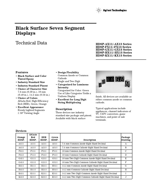
DevicesAlGaAs Orange Red HER Green Package HDSP-HDSP-HDSP-HDSP- DescriptionDrawingA411A111A211A5117.6 mm Common Anode Right Hand Decimal A A413A113A213A5137.6 mm Common Cathode Right Hand Decimal B F411F111F211F51110 mm Common Anode Right Hand Decimal C F413F113F213F51310 mm Common Cathode Right Hand Decimal D G411G111G211G51110 mm Two Digit Common Anode Right Hand Decimal E G413G113G213G51310 mm Two Digit Common Cathode Right Hand Decimal F H411H111H211H51114.2 mm Common Anode Right Hand Decimal G H413H113H213H51314.2 mm Common Cathode Right Hand Decimal H K411K111K211K51114.2 mm Two Digit Common Anode Right Hand Decimal I K413K113K213K51314.2 mm Two Digit Common Cathode Right Hand DecimalJBlack Surface Seven Segment Displays Technical DataFeatures• Black Surface and Color Tinted Epoxy• Industry Standard Size • Industry Standard Pinout • Choice of Character Size 7.6 mm (0.30 in.), 10 mm (0.40in.), 14.2 mm (0.56 in.)• Choice of ColorsAlGaAs Red, High Efficiency Red (HER), Green, Orange • Excellent Appearance Evenly Lighted Segments ±50° Viewing Angle• Design FlexibilityCommon Anode or Common CathodeSingle and Two Digit• Categorized for Luminous IntensityCategorized for Color: Green Use of Like Categories Yields a Uniform Display• Excellent for Long Digit String MultiplexingDescriptionThese devices use industrystandard size package and pinout.Available with black surfaceHDSP-AX11/-AX13 Series HDSP-FX11/-FX13 Series HDSP-GX11/-GX13 Series HDSP-HX11/-HX13 Series HDSP-KX11/-KX13 Seriesfinish. All devices are available as either common anode or common cathode.Typical applications includeappliances, channel indicators of TV, CATV converters, game machines, and point of sale terminals.Part Numbering System5082 -X X X X-X X X X XHDSP-X X X X-X X X X XMechanical Options[1]00: No Mechanical OptionColor Bin Options[1,2]0: No Color Bin LimitationMaximum Intensity Bin[1,2]0: No Maximum Intensity Bin LimitationMinimum Intensity Bin[1,2]0: No Minimum Intensity Bin LimitationDevice Configuration/Color[1]1: Common Anode3: Common CathodeDevice Specific Configuration[1]Refer to Respective DatasheetPackage[1]A: 7.6 mm (0.3 inch) Single Digit Seven Segment DisplayF: 10 mm (0.4 inch) Single Digit Seven Segment DisplayG: 10 mm (0.4 inch) Dual Digit Seven Segment DisplayH: 14.2 mm (0.56 inch) Single Digit Seven Segment DisplayK: 14.2 mm (0.56 inch) Dual Digit Seven Segment Display Notes:1. For codes not listed in the figure above, please refer to the respective datasheet or contact your nearestAgilent representative for details.2. Bin options refer to shippable bins for a part number. Color and Intensity Bins are typically restricted to 1bin per tube (exceptions may apply). Please refer to respective datasheet for specific bin limit information.Package Dimensions (7.6 mm Series)Internal Circuit DiagramPackage Dimensions (10 mm Series: Single)Internal Circuit DiagramPackage Dimensions (10 mm Series: Two Digit)Internal Circuit DiagramPackage Dimensions (14.2 mm Series: Single)Internal Circuit DiagramPackage Dimensions (14.2 mm Series: Two Digit)Internal Circuit Diagram2DIGIT NO. 1 CATHODE1Absolute Maximum RatingsAlGaAs Red HER/Orange GreenHDSP-X11X HDSP-X21X/X41X HDSP-X51X Description Series Series Series Units Average Power per Segment37105105mW or DPPeak Forward Current per4590[1]90[3]mA Segment or DPDC Forward Current per15[5]30[2]30[4]mA Segment or DPOperating Temperature Range–20 to +100 –40 to +100°C Storage Temperature Range–55 to +100°C Reverse Voltage per 3.0V Segment or DPWave Soldering Temperature for250°C 3 Seconds (1.60 mm [0.063 in.]below Body)Notes:1. See Figure 5 to establish pulsed conditions.2. Derate above 53°C at 0.45 mA/°C (see Figure 7).3. See Figure 6 to establish pulsed conditions.4. Derate above 39°C at 0.37 mA/°C (see Figure 7).5. Derate above 91°C at 0.53 mA/°C (see Figure 1).Electrical/Optical Characteristics at T A = 25°CAlGaAs RedDevice SeriesHDSP-Parameter Symbol Min.Typ.Max.Units Test Conditions A11X Luminous Intensity/Segment[1,2]I V315600µcd I F = 1 mA (Digit Average)3600I F = 5 mAF11X, G11X330650I F = 1 mA3900I F = 5 mAH11X, K11X400700I F = 1 mA4200I F = 5 mAAll Devices Forward Voltage/Segment or DP V F 1.6 2.0V I F = 1 mA1.7I F = 5 mA1.822I F = 20 mA PeakPeak WavelengthλP EAK645nmDominant Wavelength[3]λd637nmReverse Voltage/Segment or DP[4]V R 3.015V I R = 100 µATemperature Coefficient of∆V F/°C-2mV/°CV F/Segment or DPA11X Thermal Resistance LED RθJ-PIN255°C/W/Junction-to-Pin Seg.F11X, G11X320H11X, K12X400OrangeDevice SeriesHDSP-Parameter Symbol Min.Typ.Max.Units Test Conditions A41X Luminous Intensity/Segment I V0.70mcd I F = 5 mA (Segment Average)[1,2]F41X, G41X 1.0I F = 5 mAH41X, K41X 2.37I F = 10 mAAll Forward Voltage/Segment or DP V F 2.0 2.5V I F = 20 mA DevicesPeak WavelengthλPEAK600nmDominant Wavelength[3]λd603nmReverse Voltage/Segment or DP[4]V R 3.030V I R = 100 µATemperature Coefficient of∆V F/°C–2mV/°CV F/Segment or DPA41X Thermal Resistance LED RθJ-PIN200°C/W/Junction-to-Pin Seg.F41X, G41X320H41X, K41X345High Efficiency RedDevice SeriesHDSP-Parameter Symbol Min.Typ.Max.Units Test Conditions A21X Luminous Intensity/Segment[1,2]I V360980µcd I F = 5 mA (Digit Average)5390I F = 20 mAF21X, G21X4201200I F = 5 mAH21X, K21X9002800I F = 10 mA3700I F = 60 mA Peak:1/6 Duty Factor All Forward Voltage/Segment or DP V F 2.0 2.5V I F = 20 mA DevicesPeak WavelengthλPEAK635nmDominant Wavelength[3]λd626nmReverse Voltage/Segment or DP[4]V R 3.030V I R = 100 µATemperature Coefficient of∆V F/°C-2mV/°CV F/Segment or DPA21X Thermal Resistance LED RθJ-PIN200°C/W/Junction-to-Pin Seg.F21X, G21X320H21X, K21X345High Performance GreenDevice SeriesHDSP-Parameter Symbol Min.Typ.Max.Units Test ConditionsA51X Luminous Intensity/Segment[1,2]I V8603000µcd I F = 10 mA (Digit Average)6800I F = 20 mAF51X, G51X10303500I F = 10 mAH51X, K51X9002500I F = 10 mA3100I F = 60 mA Peak:1/6 Duty FactorAll Forward Voltage/Segment or DP V F 2.1 2.5V I F = 10 mADevicesPeak WavelengthλPEAK566nmDominant Wavelength[3,5]λd571577nmReverse Voltage/Segment or DP[4]V R 3.050V I R = 100 µATemperature Coefficient of∆V F/°C-2mV/°CV F/Segment or DPA51X Thermal Resistance LED RθJ-PIN200°C/W/Junction-to-Pin Seg.F51X, G51X320H51X, G51X345Notes:1. Case temperature of device immediately prior to the intensity measurement is 25°C.2. The digits are categorized for luminous intensity. The intensity category is designated by a letter on the side of the package.3. The dominant wavelength, λd, is derived from the CIE chromaticity diagram and is that single wavelength which defines the color ofthe device.4. Typical specification for reference only. Do not exceed absolute maximum ratings.5. Green (HDSP-A51X/F51X/G51X/H512X/K51X) series displays are categorized for dominant wavelength. The category is designated bya number adjacent to the luminous intensity category letter.Figure 3. Relative Luminous Intensity vs. DC Forward Current.Figure 4. Relative Efficiency (LuminousIntensity per Unit Current) vs. Peak Current.Figure 1. Maximum Allowable Average orDC Current vs. Ambient Temperature.Figure 2. Forward Current vs. Forward Voltage.16024681012142010090807060504030T – AMBIENT TEMPERATURE – °C AI A V E . M A X – M A X I M U M A V E R A G E F O R W A R D C U R R E N T P E R S E G M E N T – m AF 1201102018F 50.020.010.05.02.01.00.50.10.51.01.52.02.5V – FORWARD VOLTAGE – VF I – F O R W A R D C U R R E N TP E R S E G M E N T – m A20105210.50.20.10.10.20.51251020R E L A T I V E L U M I N O U S I N T E N S I T Y (N O R M A L I Z E D T O 1 A T 1 m A )I – FORWARD CURRENT PER SEGMENT – mAF I – PEAK FORWARD CURRENTPER SEGMENT – mAPEAK η –R E L A T I V E E F F I C I E N C Y – N O R M A L I Z E D T O 1 A T 1 m AP E A K 1.31.21.11.00.90.80.7AlGaAs RedHER, Green, OrangeFigure 7. Maximum Allowable DCCurrent vs. Ambient Temperature.Figure 8. Forward Current vs.Forward Voltage Characteristics.Figure 9. Relative Luminous Intensity vs. DC Forward Current.Figure 10. Relative Efficiency (Luminous Intensity per Unit Current) vs. Peak Current.40051015202530352010090807060504030T – AMBIENT TEMPERATURE – °CA I M A X – M A X I M U M D C C U R R E N T P E R S E G M E N T – m AD C 1201105045010080604020I – F O R W A R D C U R R E N T P E R S E G M E N T – m AF 2.04.03.01.0V –FORWARD VOLTAGE – VF 05.0ηP E A K – R E L A T I V E L U M I N O U S I N T E N S I T Y (N O R M A L I Z E D T O 1 A T 5 m A F O R H E R ,A N D T O 1 A T 10 m A F O R G R E E N )150108642205301025I – FORWARD CURRENT PER SEGMENT – mAF 0I – PEAK FORWARD CURRENTPER SEGMENT – mAPEAK ηP E A K – R E L A T I V E E F F I C I E N C Y (N O R M A L I Z E D T O 1 A T 5 m A F O R H E R ,A N D 10 m A F O R G R E E N )Figure 5. Maximum Tolerable Peak Currentvs. Pulse Duration – HER, Orange.Figure 6. Maximum Tolerable Peak Current vs. Pulse Duration – Green.R A T I O O F M A X I M U M O P E R A T I N G P E A K C U R R E N T T O T E M P E R A T U R E D E R A T E D D C C U R R E N TI P E A K F I M A X D C t – PULSE DURATION – µsP 101100DC R A T I O O F M A X I M U M O P E R A T I N G P E A K C U R R E N T T O T E M P E R A T U R E D E R A T E D D C C U R R E N TI P E A K FI M A X D C t – PULSE DURATION – µs P 101100DCHDSP-A1xx IV Bin Category Min.Max.E 0.3150.520F 0.4280.759G 0.621 1.16H 0.945 1.71I 1.40 2.56J 2.10 3.84K 3.14 5.75L 4.708.55Intensity Bin Limits (mcd)AlGaAs RedHDSP-F1xx/G1xx IV Bin Category Min.Max.D 0.3910.650E 0.5320.923F 0.755 1.39G 1.13 2.08H 1.703.14HDSP-H1xx/K1xx IV Bin Category Min.Max.C 0.4150.690D 0.5650.990E 0.810 1.50F 1.20 2.20G 1.80 3.30H 2.73 5.00I 4.097.50OrangeHDSP-A41XIV Bin Category MinMaxA 0.2840.433B 0.3540.541C 0.4430.677D 0.5540.846E 0.692 1.057F 0.856 1.322G 1.082 1.652H 1.352 2.066I 1.692 2.581J 2.114 3.227K 2.641 4.034L 3.300 5.042M 4.127 6.303N 5.1577.878HDSP-F41X/G41XIV Bin Category MinMaxC 0.4850.890D 0.728 1.333E 1.091 2.000F 1.636 3.000G 2.454 4.500H 3.6826.751HDSP-H41X/K41XIV Bin Category MinMaxB 0.77 1.17C 0.95 1.45D 1.19 1.82E 1.49 2.27F 1.85 2.89G 2.32 3.54H 2.904.43Intensity Bin Limits (mcd), continued HERMin.Max.B0.3420.630C0.5160.946D0.774 1.418E 1.160 2.127F 1.740 3.190G 2.610 4.785H 3.9157.177Min.Max.C0.4850.890D0.728 1.333E 1.091 2.000F 1.636 3.000G 2.454 4.500H 3.682 6.751Min.Max.E0.91 1.67F 1.37 2.51G 2.05 3.76H 3.08 5.64I 4.628.64J 6.9312.70K10.3919.04Contrast EnhancementFor information on contrast enhancement, please see Application Note 1015.Soldering/CleaningFor information on soldering LEDs, please refer to Application Note 1029.Electrical/OpticalFor more information onelectrical/optical characteristics,please see Application Note 1005.Color CategoriesNote:All categories are established for classification of products. Products may not be available in all categories. Please contact your Agilent representatives for further clarification/information.HDSP-A5xx IV Bin Category Min.Max.H 0.86 1.58I 1.29 2.37J 1.94 3.55K 2.90 5.33L 4.378.01Intensity Bin Limits (mcd), continued GreenHDSP-F5xx/G5xx IV Bin Category Min.Max.H 1.54 2.82I 2.31 4.23J 3.46 6.34K 5.189.50L 7.7814.26HDSP-H5xx/K5xx IV Bin Category Min.Max.E 0.91 1.67F 1.37 2.51G 2.05 3.76H 3.08 5.64I 4.618.46/semiconductors For product information and a complete list of distributors, please go to our web site.For technical assistance call:Americas/Canada: +1 (800) 235-0312 or (916) 788-6763Europe: +49 (0) 6441 92460China: 10800 650 0017Hong Kong: (+65) 6756 2394India, Australia, New Zealand: (+65) 6755 1939 Japan: (+81 3) 3335-8152 (Domestic/Interna-tional), or 0120-61-1280 (Domestic Only) Korea: (+65) 6755 1989Singapore, Malaysia, Vietnam, Thailand, Philippines, Indonesia: (+65) 6755 2044 Taiwan: (+65) 6755 1843Data subject to change.Copyright © 2004 Agilent Technologies, Inc. Obsoletes 5988-1742ENJuly 17, 20045988-4433EN。
HV300系列通用型变频器选型手册说明书

HV300系列通用型变频器选型手册(0.4kW~500kW)通用技术规格公司简介质量管理体系环境管理体系职业健康安全管理体系【质量体系】深圳市禾望电气股份有限公司(股票代码603063)是一家专注于电力电子产品研发、制造、营销和服务的高新技术企业,产品涵盖大功率兆瓦级风电变频器、工程型变频器、通用变频器、光伏逆变器、SVG静止无功发生器、岸电电源和储能变流器等,现已成为国内技术和业绩领先的电气企业。
在工业传动领域,禾望电气在强大的定制工程型风电变频器平台基础上,自主研发了HD2000系列低压工程型变频器、HD8000系列中压多电平变频器和HV500系列高性能变频器,此外,禾望电气还拥有HV300系列通用变频器、油田专用HEC系列变频器,禾望电气的工业传动产品涵盖各个功率段及多种控制方式,适用于各种工业场景。
中国 · 深圳总部总部及研发基地:深圳制造基地:深圳、苏州、东莞、盐城营销服务中心:北京、上海、俄罗斯服务基地:华南、华东、西南、西北、华北、东北片区等16个服务基地和遍布全国的服务点。
【荣誉】CNAS认可实验室资质国家级高新技术企业国家科学技术进步奖产品外形尺寸(详见产品尺寸表)变频器系列名:HV300:hopeVert系列,通用型电路拓扑及冷却方式:A0:两象限风冷 W0:两象限水冷A1:四象限风冷 W1:四象限水冷电压等级:2:220V 4:380V 6:690V相数:D:单相/三相 T:三相负载类型:G:标准G型机E:小体积G型机空:G/P合一型机制动单元信息:B:内置制动单元空:无内置制动单元功率等级:00007:0.7kW 00075:7.5kW 00150:15kW 01850:185kW 20000:2MWHV300 — A0 2 T 00007 G B产品选型指引通用技术规格本节所述功率等级规格针对标准四极三相交流异步电动机而给出。
G、E:恒转矩负载。
P:风机、泵类负载。
ASTMA513-00(2000)电阻焊碳钢与合金钢机械用钢管
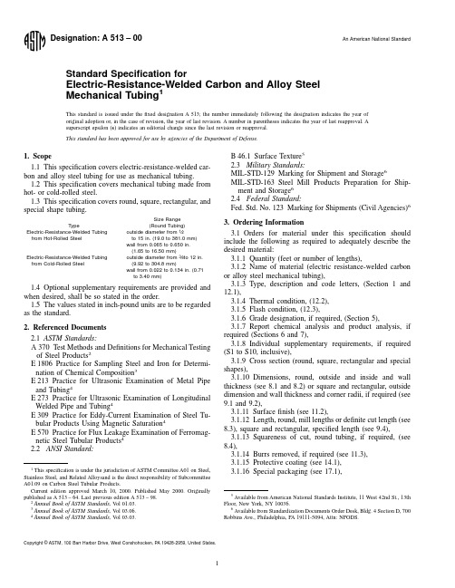
3.1.17Specification designation,3.1.18End use,3.1.19Special requirements,3.1.20Special marking (Section 16),and3.1.21Straightness Test Method (see 8.5and 9.6).4.Materials and Manufacture4.1The steel may be made by any process.4.2If a specific type of melting is required by the purchaser,it shall be as stated on the purchase order.4.3The primary melting may incorporate separate degas-sing or refining,and may be followed by secondary melting,such as electroslag or vacuum-arc remelting.If secondarymelting is employed,the heat shall be defined as all of theingots remelted from a single primary heat.4.4Steel may be cast in ingots or may be strand cast.Whensteel of different grades is sequentially strand cast,identifica-tion of the resultant transition material is required.Theproducer shall remove the transition material by an establishedprocedure that positively separates the grades.4.5Tubes shall be made by the electric-resistance-weldedprocess and shall be made from hot-or cold-rolled steel asspecified.5.Chemical Composition5.1The steel shall conform to the requirements as tochemical composition prescribed in Tables 1and 2.If no gradeis specified,Grades MT 1010to MT 1020may be furnished.Analyses of steels other than those listed are available.Todetermine their availability,the purchaser should contact theproducer.5.2When a carbon steel grade is ordered under this speci-fication,supplying an alloy grade that specifically requires theaddition of any element other than those listed for the orderedgrade in Tables 1and 2is not permitted.6.Heat Analysis6.1An analysis of each heat of steel shall be made by thesteel manufacturer to determine the percentages of the ele-ments specified;if secondary melting processes are employed,the heat analysis shall be obtained from one remelted ingot orthe product of one remelted ingot of each primary melt.The heat analysis shall comform to the requirements specified,except that where the heat identity has not been maintained or where the analysis is not sufficiently complete to permit conformance to be determined,the chemical composition determined from a product analysis made by the tubular manufacturer shall conform to the requirements specified for heat analysis.When requested in the order or contract,a report of such analysis shall be furnished to the purchaser.7.Product Analysis 7.1When requested on the purchase order,a product analy-sis shall be made by the supplier.The number and source of samples for such product analysis shall be based on the individual heat or lot identity of one of the following forms of material:7.1.1Heat Identity Maintained —One product analysis per heat shall be made on either the flat-rolled stock or tube.7.1.2Heat Identity Not Maintained —A product from one tube per 2000ft (610m)or less for sizes over 3in.(76.2mm),and one tube per 5000ft (150m)or less for sizes 3in.and under.7.2Samples for product analysis except for spectrochemical analysis shall be taken in accordance with Practice E 1806.The composition thus determined shall correspond to the require-ments of Tables 1-3.7.3If the original test for product analysis fails,retests of two additional lengths of flat-rolled stock or tubes shall be made.Both retests for the elements in question shall meet the requirements of the specification;otherwise,all remaining material in the heat or lot shall be rejected or,at the option of the producer,each length of flat-rolled stock or tube may be individually tested for acceptance.Lengths of flat-rolled stock or tubes which do not meet the requirements of the specifica-tion shall be rejected.8.Permissible Variations in Dimensions for Round Tubing 8.1Diameter and Wall Thickness (Hot-Rolled Steel)—Variations from specified outside diameter for “as-welded”and “as-welded and annealed”tubing made from hot-rolled steel shall not exceed the amounts prescribed in Table 4.Permissible variations in outside diameter for tubing that has been sink-drawn for closer tolerance on outside diameter are shown in Table 5.Permissible variations in wall thickness for tubing that has been sink-drawn for closer tolerances on outside diameters are 610%of the nominal wall or 60.010in.(0.25mm),whichever is greater.Permissible variations in wall thickness for tubing made from hot-rolled steel are shown in Table 6.Permissible variation in outside and inside diameter for tubing made from hot-rolled steel that has been mandrel drawn for closer tolerances are shown in Table 5with wall tolerances shown in Table 7.8.2Diameter and Wall Thickness (Cold-Rolled Steel)—Variations in outside diameter and inside diameter of “as-welded”and “as-welded and annealed”tubing made from cold-rolled steel are shown in Table 8.Outside diameter tolerances for cold-rolled steel tubing,sink drawn and mandrel drawn,are shown in Table 5.Wall thickness tolerances for“TABLE 1Chemical Requirements for Standard Low-CarbonSteels AN OTE 1—Chemistry represents heat analysis.Product analysis,exceptfor rimmed or capped steel,is to be in accordance with usual practice asshown in Table 3.Grade Designation Chemical Composition Limits,%Carbon Manganese Phosphorus,max Sulfur,maxMT B 10100.05–0.150.30–0.600.0350.035MT 10150.10–0.200.30–0.600.0350.035MT X 10150.10–0.200.60–0.900.0350.035MT 10200.15–0.250.30–0.600.0350.035MT X 10200.15–0.250.70–1.000.0350.035A Rimmed or capped steels which may be used for the above grades arecharacterized by a lack of uniformity in their chemical composition,and for thisreason product analysis is not technologically appropriate unless misapplication isclearly indicated.B The letters MT under grade designation indicate MechanicalTubing.as-welded”tubing made from cold-rolled steel are shown inTable 9.Permissible variations in wall thickness for roundtubing,mandrel drawn for closer tolerances,are shown inTable 7.Permissible variations in wall thickness for tubing thathas been sink-drawn for closer tolerances on outside diameter are 610%of the nominal wall or 60.010in.(0.25mm),whichever is greater.8.3Length (Hot-and Cold-Rolled Steel)—Mechanical tub-ing is commonly furnished in mill lengths 5ft (1.5m)and over.Definite cut lengths are furnished when specified by the purchaser.Tolerances for definite cut lengths round tubing shall be as given in Tables 10and 11.8.4Squareness of Cut (Hot-and Cold-Rolled Steel)—When specified,tolerance for squareness of cut of round tubing shall be as given in Table 12.Measurements are made with use of an “L”square and feeler gage.Side leg of square to be equal to tube diameter except minimum length of 1in.(25.4mm)and maximum length of 4in.(101.6mm).Outside diameter burr to be removed for measurement.8.5Straightness —The straightness tolerance for round tubing is 0.030in./3ft (0.76mm/1m)lengths to 8.000in.(203mm)outside diameter.For 8.000in.outside diameter and above,straightness tolerance is 0.060in./3ft (1.52mm/1m)lengths.For lengths under 1ft the straightness tolerance shall be agreed upon between the purchaser and producer.The test method for straightness measurement is at the manufacturer’s option,unless a specific test method is specified in the purchase order.8.6Ovality (Hot-and Cold-Rolled Steel)—The ovality shall be within the tolerances except when the wall thickness is less than 3%of the outside diameter.8.6.1In such cases for Types 1and 2(A.W.H.R.andTABLE 2Chemical Requirements for Other Carbon and Alloy Steels AN OTE 1—Chemistry represents heat analysis.Product analysis,except for rimmed or capped steel,is to be in accordance with usual practice as shown in Table 3.GradeDesignationChemical Composition Limits,%Carbon Manganese Phosphorus,max Sulfur,max Silicon Nickel Chromium Molybdenum 10080.10max 0.50max 0.0350.035 (1010)0.08–0.130.30–0.600.0350.035 (1012)0.10–0.150.30–0.600.0350.035 (1015)0.12–0.180.30–0.600.0350.035 (1016)0.12–0.180.60–0.900.0350.035 (1017)0.14–0.200.30–0.600.0350.035 (1018)0.14–0.200.60–0.900.0350.035 (1019)0.14–0.200.70–1.000.0350.035 (1020)0.17–0.230.30–0.600.0350.035 (1021)0.17–0.230.60–0.900.0350.035 (1022)0.17–0.230.70–1.000.0350.035 (1023)0.19–0.250.30–0.600.0350.035 (1024)0.18–0.25 1.30–1.650.0350.035 (1025)0.22–0.280.30–0.600.0350.035 (1026)0.22–0.280.60–0.900.0350.035 (1027)0.22–0.29 1.20–1.550.0350.035 (1030)0.27–0.340.60–0.900.0350.035 (1033)0.29–0.360.70–1.000.0350.035 (1035)0.31–0.380.60–0.900.0350.035 (1040)0.36–0.440.60–0.900.0400.050 (1050)0.47–0.550.60–0.900.0400.050 (1060)0.55–0.660.60–0.900.0400.050 (1340)0.38–0.43 1.60–1.900.0350.0400.15–0.35 (1524)0.18–0.25 1.35–1.650.0400.050 (4118)0.18–0.230.70–0.900.0350.0400.15–0.35...0.40–0.600.08–0.1541300.28–0.330.40–0.600.0350.0400.15–0.35...0.80–1.100.15–0.2541400.38–0.430.75–1.000.0350.0400.15–0.35...0.80–1.100.15–0.2551300.23–0.330.70–0.900.0350.0400.15–0.35...0.80–1.10 (8620)0.18–0.230.70–0.900.0350.0400.15–0.350.40–0.700.40–0.600.15–0.2586300.28–0.330.70–0.900.0350.0400.15–0.350.40–0.700.40–0.600.15–0.25A Where the ellipsis (...)appears in this table,there is no requirement.TABLE 3Tolerances for Product Analysis for Steels Shown inTables 1and 2A ,BElement Limit,or Maximum of Specified Range,%Variation,Over theMaximum Limit or Underthe Minimum LimitUnder min,%Over max,%Carbon to 0.15,incl 0.020.03over 0.15to 0.40,incl 0.030.04over 0.40to 0.55,incl 0.030.05Manganese to 0.60,incl 0.030.03over 0.60to 1.15,incl 0.040.04over 1.15to 1.65,incl 0.050.05Phosphorus ...0.01Sulfur ...0.01Silicon to 0.30,incl 0.020.03over 0.30to 0.600.050.05Nickel to 1.00,incl 0.030.03Chromium to 0.90,incl 0.030.03over 0.90to 2.10,incl 0.050.05Molybdenumto 0.20,incl 0.010.01over 0.20to 0.40,incl 0.020.02A Individual determinations may vary from the specified heat limits or ranges tothe extent shown in this table,except that any element in a heat may not vary bothabove and below a specified range.B Where the ellipsis (...)appears in this table,there is norequirement.A.W.C.R.)the ovality may be 50%greater than the outsidetolerances but the mean outside diameter shall be within thespecified tolerance.8.6.2For Types 3,4,5,and 6(S.D.H.R.,S.D.C.R.,M.D.,and S.S.I.D.)the additional ovality shall be as follows but the mean outside diameter shall be within the specified tolerance:TABLE 4Diameter Tolerances for Type I (A.W.H.R.)Round TubingN OTE 1—Measurements for diameter are to be taken at least 2in.A from the ends of the tubes.Outside DiameterRange,in.AWall ThicknessFlash-in-Tubing B ,C Flash Controlled to 0.010in.max Tubing C ,D Flash Controlled to 0.005in.max Tubing E ,D BwgF in.A Outside Diameter,6Outside Diameter,6Outside Diameter,6Inside Diameter,6Tolerances,in.A ,G 1⁄2to 11⁄8,incl16to 100.065to 0.1340.00350.00350.00350.020Over 11⁄8to 2,incl 16to 140.065to 0.0830.0050.0050.0050.021Over 11⁄8to 2,incl 13to 70.095to 0.1800.0050.0050.0050.025Over 11⁄8to 2,incl 6to 50.203to 0.2200.0050.0050.0050.029Over 11⁄8to 2,incl 4to 30.238to 0.2590.0050.0050.0050.039Over 2to 21⁄2,incl 16to 140.065to 0.0830.0060.0060.0060.022Over 2to 21⁄2,incl 13to 50.095to 0.2200.0060.0060.0060.024Over 2to 21⁄2,incl 4to 30.238to 0.2590.0060.0060.0060.040Over 21⁄2to 3,incl 16to 140.065to 0.0830.0080.0080.0080.024Over 21⁄2to 3,incl 13to 50.095to 0.2200.0080.0080.0080.026Over 21⁄2to 3,incl 4to 30.238to 0.2590.0080.0080.0080.040Over 21⁄2to 3,incl 2to 0.3200.284to 0.3200.0100.0100.0100.048Over 3to 31⁄2,incl 16to 140.065to 0.0830.0090.0090.0090.025Over 3to 31⁄2,incl 13to 50.095to 0.2200.0090.0090.0090.027Over 3to 31⁄2,incl 4to 30.238to 0.2590.0090.0090.0090.043Over 3to 31⁄2,incl 2to 0.3600.284to 0.3600.0120.0120.0120.050Over 31⁄2to 4,incl 16to 140.065to 0.0830.0100.0100.0100.026Over 31⁄2to 4,incl 13to 50.095to 0.2200.0100.0100.0100.028Over 31⁄2to 4,incl 4to 30.238to 0.2590.0100.0100.0100.044Over 31⁄2to 4,incl 2to 0.5000.284to 0.5000.0150.0150.0150.053Over 4to 5,incl 16to 140.065to 0.0830.0200.0200.0200.036Over 4to 5,incl 13to 50.095to 0.2200.0200.0200.0200.045Over 4to 5,incl 4to 30.238to 0.2590.0200.0200.0200.054Over 4to 5,incl 2to 0.5000.284to 0.5000.0200.0200.0200.058Over 5to 6,incl 16to 100.065to 0.1340.0200.0200.0200.036Over 5to 6,incl 9to 50.148to 0.2200.0200.0200.0200.040Over 5to 6incl 4to 30.238to 0.2590.0200.0200.0200.054Over 5to 6,incl 2to 0.5000.284to 0.5000.0200.0200.0200.058Over 6to 8,incl 11to 100.120to 0.1340.0250.0250.0250.043Over 6to 8,incl 9to 50.148to 0.2200.0250.0250.0250.045Over 6to 8,incl 4to 30.238to 0.2590.0250.0250.0250.059Over 6to 8,incl 2to 0.5000.284to 0.5000.0250.0250.0250.063Over 8to 10,incl 14to 120.083to 0.1090.0300.0300.0300.041Over 8to 10,incl 11to 100.120to 0.1340.0300.0300.0300.043Over 8to 10,incl 9to 50.148to 0.2200.0300.0300.0300.045Over 8to 10,incl 4to 30.238to 0.2590.0300.0300.0300.059Over 8to 10,incl 2to 0.5000.248to 0.5000.0300.0300.0300.063Over 10to 12,incl 14to 120.083to 0.1090.0350.0350.0350.041Over 10to 12,incl 11to 100.120to 0.1340.0350.0350.0350.043Over 10to 12,incl 9to 50.148to 0.2200.0350.0350.0350.045Over 10to 12,incl 4to 30.238to 0.2590.0350.0350.0350.059Over10to 12,incl 2to 0.5000.284to 0.5000.0350.0350.0350.063A1in.525.4mm.B Flash-In-Tubing is produced only to outside diameter tolerances and wall thickness tolerances and the inside diameter welding flash does not exceed the wall thickness or 3⁄32in.,whichever is less.C Flash Controlled to 0.010in.maximum tubing consists of tubing which is commonly produced only to outside diameter tolerances and wall thickness tolerances,in which the height of the remaining welding flash is controlled not to exceed 0.010in.D No Flash tubing is further processed for closer tolerances with mandrel-tubing produced to outside diameter and wall,inside diameter and wall,or outside diameter and inside diameter to tolerances with no dimensional indication of inside diameter flash.This condition is available in Types 5and 6.E Flash Controlled to 0.005in.maximum tubing is produced to outside diameters and wall thickness tolerance,inside diameter and wall thickness tolerances,or outside diameters and inside diameter tolerances,in which the height of the remaining flash is controlled not to exceed 0.005in.Any remaining flash is considered to be part of the applicable inside diameter tolerances.F Birmingham Wire Gage.G The ovality shall be within the above tolerances except when the wall thickness is less than 3%of the outside diameter,in such cases see8.6.1.Outside Diameter,in.(mm)Additional OvalityTolerance,in.(mm)Up to 2(50.8),incl 0.010(0.25)Over 2to 3(50.8to 76.2),incl 0.015(0.38)Over 3to 4(76.2to 101.6),incl 0.020(0.51)Over 4to 5(101.6to 127.0),incl 0.025(0.64)Over 5to 6(127.0to 152.4),incl 0.030(0.76)Over 6to 7(152.4to 177.8),incl 0.035(0.89)Over 7to 8(177.8to 203.2),incl 0.040(1.02)Over 8to 9(203.2to 228.6),incl 0.045(1.14)Over 9to 10(228.6to 254.0),incl 0.050(1.27)Over 10to 11(254.0to 279.4),incl 0.055(1.40)Over 11to 12(279.4to 304.8),incl 0.060(1.52)Over 12to 12.500(304.8to 317.5),incl 0.065(1.65)9.Permissible Variations in Dimensions of Square andRectangular Tubing9.1Diameter and Wall Thickness —Permissible variationsin outside dimensions for square and rectangular tubing shall be as given in Table 13.The wall thickness tolerance is 610%of the nominal wall thickness.9.2Corner Radii —Unless otherwise specified,the corners of square and rectangular tubing shall be slightly rounded inside and outside,consistent with wall thickness.The outside corners may be slightly flattened.The radii of corners shall be as given in Table 14.9.3Squareness —Permissible variations for squareness shall be determined by the following equation:6b 5c x 0.006in.where:b 5tolerance for out-of-square,and c 5largest external dimension across flats.The squareness of sides is commonly determined by one of the following methods.9.3.1A square with two adjustable contact points on each arm,is placed on two sides.A fixed feeler gage is then used to measure the maximum distance between the free contact point and the surface of the tubing.9.3.2A square equipped with a direct reading vernier,may be used to determine the angular deviation which,in turn,may be related to distance in inches.9.4Length —Variations from the specified length shall not exceed the amount prescribed in Table 15.9.5Twist —Twist tolerances are shown in Table 16.The twist in square and rectangular tubing may be measured by holding one end of the tubing on a surface plate and noting the height of either corner of the opposite end of same side above the surface plate.Twist may also be measured by the use of a beveled protractor equipped with a level,and noting the angular deviation on opposite ends,or at any point throughout the length.9.6Straightness —The straightness tolerance is 1⁄16in./3ft (1.7mm/1m).The test method for straightness measurement is at the manufacturer’s option,unless a specific test method is specified in the purchase order.10.Tubing Sections Other Than Square and Rectangular 10.1In addition to square and rectangular tubing,many producers supply a variety of special sections,such as oval,streamlined,hexagonal,octagonal,round inside and hexagonal or octagonal outside,ribbed inside or out,triangular,rounded rectangular and D shapes.Manufacturing practices limit the size range and section available from the various producers.These special sections may be made through turkshead rolls or through a die with or without use of a mandrel.Since the sections are special,dies and other tools are not held available.Therefore,when inquiring for shapes other than square and rectangular,it is essential to give full details as to dimensions and finish.11.Workmanship,Finish,and Appearance 11.1The tubing shall be free of injurious defects and shall have a workmanlike finish.11.2Unless otherwise specified in the purchase order,the tubing shall be free of scale.In the case of thermally treated tubing a slight amount of color will not be considered cause for rejection.TABLE 5Diameter Tolerances for Types 3,4,5,and 6(S.D.H.R.,S.D.C.R.,M.D.and S.S.I.D)Round TubingN OTE 1—Measurements for diameter are to be taken at least 2in.fromthe ends of the tubes.OD Size Range AWall %of OD Types 3,4,(SinkDrawn)A ,B and 5,6,(Mandrel Drawn)B ,C OD,in.Types 5and 6(Man-drel Drawn)B ,C ,D ID in.Over Under Over UnderUp to 0.499all 0.0040.000......0.500to 1.699all 0.0050.0000.0000.0051.700to2.099all 0.0060.0000.0000.0062.100to 2.499all 0.0070.0000.0000.0072.500to 2.899all 0.0080.0000.0000.0082.900to3.299all 0.0090.0000.0000.0093.300to 3.699all 0.0100.0000.0000.0103.700to4.099all 0.0110.0000.0000.0114.100to 4.499all 0.0120.0000.0000.0124.500to 4.899all 0.0130.0000.0000.0134.900to5.299all 0.0140.0000.0000.0145.300to 5.549all 0.0150.0000.0000.0155.550to 5.999under 60.0100.0100.0100.0106and over 0.0090.0090.0090.0096.000to 6.499under 60.0130.0130.0130.0136and over 0.0100.0100.0100.0106.500to 6.999under 60.0150.0150.0150.0156and over 0.0120.0120.0120.0127.000to 7.499under 60.0180.0180.0180.0186and over 0.0130.0130.0130.0137.500to 7.999under 60.0200.0200.0200.0206and over 0.0150.0150.0150.0158.000to 8.499under 60.0230.0230.0230.0236and over 0.0160.0160.0160.0168.500to 8.999under 60.0250.0250.0250.0256and over 0.0170.0170.0170.0179.000to 9.499under 60.0280.0280.0280.0286and over 0.0190.0190.0190.0199.500to 9.999under 60.0300.0300.0300.0306and over 0.0200.0200.0200.02010.000to 10.999all 0.0340.0340.0340.03411.000to 11.999all 0.0350.0350.0350.03512.000to 12.999all 0.0360.0360.0360.03613.000to 13.999all 0.0370.0370.0370.03714.000to 14.999all 0.0380.0380.0380.038A Tubing,flash in or flash controlled which is further processed without mandrelto obtain tolerances closer than those shown in Tables 4and 8.B The ovality shall be within the above tolerances except when the wallthickness is less than 3%of the outside diameter,in such cases see 8.6.2.C Tubing produced to outside diameter and wall thickness,or inside diameterand wall thickness,or outside diameter and inside diameter,with mandrel to obtaintolerances closer than those shown in Tables 4and 8and no dimensionalindication of inside diameter flash.D Where the ellipsis (...)appears in this table,the tolerance is notaddressed.T A B L E 6W a l l T h i c k n e s s T o l e r a n c e f o r T y p e I (A .W .H .R .)R o u n d T u b i n g W a l l t h i c k n e s s O u t s i d e D i a m e t e r ,i n .A3⁄4t o 1,i n c lO v e r 1t o115⁄16,i n c l O v e r 115⁄16t o 33⁄4,i n c l O v e r 33⁄4t o 41⁄2,i n c l O v e r 41⁄2t o 6,i n c lO v e r 6t o 8,i n c l O v e r 8t o 10,i n c l O v e r 10t o 12,i n c l i n .A B w g B W a l l T h i c k n e s s T o l e r a n c e s ,i n .,6C+−+−+−+−+−+–+–+–0.065160.0050.0090.0040.0100.0030.0110.0020.0120.0020.0120.0020.012............0.072150.0050.0090.0040.0100.0030.0110.0020.0120.0020.0120.0020.0120.0030.013......0.083140.0060.0100.0050.0110.0040.0120.0030.0130.0030.0130.0030.0130.0030.0130.0030.0130.095130.0060.0100.0050.0110.0040.0120.0030.0130.0030.0130.0030.0130.0030.0130.0030.0130.109120.0060.0100.0050.0110.0040.0120.0030.0130.0030.0130.0030.0130.0030.0130.0030.0130.120110.0060.0100.0050.0110.0040.0120.0030.0130.0030.0130.0030.0130.0030.0130.0030.0130.134100.0060.0100.0050.0110.0040.0120.0030.0130.0030.0130.0030.0130.0030.0130.0030.0130.1489......0.0060.0120.0050.0130.0040.0140.0040.0140.0040.0140.0040.0140.0040.0140.1658......0.0060.0120.0050.0130.0040.0140.0040.0140.0040.0140.0040.0140.0040.0140.1807......0.0060.0120.0050.0130.0040.0140.0040.0140.0040.0140.0040.0140.0040.0140.2036............0.0070.0150.0060.0160.0050.0170.0050.0170.0050.0170.0050.0170.2205............0.0070.0150.0060.0160.0050.0170.0050.0170.0050.0170.0050.0170.2384............0.0120.0200.0110.0210.0100.0220.0100.0220.0100.0220.0100.0220.2593............0.0130.0210.0120.0220.0110.0230.0110.0230.0110.0230.0110.0230.2842............0.0140.0220.0130.0230.0120.0240.0120.0240.0120.0240.0120.0240.3001............0.0150.0230.0140.0240.0130.0250.0130.0250.0130.0250.0130.0250.320............0.0160.0240.0150.0250.0140.0260.0140.0260.0140.0260.0140.0260.344............0.0170.0250.0160.0260.0150.0270.0150.0270.0150.0270.0150.0270.360............0.0170.0250.0160.0260.0150.0270.0150.0270.0150.0270.0150.0270.375..................0.0160.0260.0150.0270.0150.0270.0150.0270.0150.0270.406..................0.0170.0270.0160.0280.0160.0280.0160.0280.0160.0280.438..................0.0170.0270.0160.0280.0160.0280.0160.0280.0160.0280.469........................0.0160.0280.0160.0280.0160.0280.0160.0280.500........................0.0160.0280.0160.0280.0160.0280.0160.028A 1i n .525.4m m .B B i r m i n g h a m W i r e G a g e .C W h e r e t h e e l l i p s i s (...)a p p e a r s i n t h i s t a b l e ,t h e t o l e r a n c e i s n o t a d d r e s s e d.11.3When burrs must be removed from one or both ends,itshall be specified in the purchase order.12.Condition12.1The types and conditions of tubing covered by thisspecification are:TypeNumber Code Letters Description1 A.W.H.R.“as-welded”from hot-rolled steel2 A.W.C.R.“as-welded”from cold-rolled steel3S.D.H.R.“sink-drawn”hot-rolled steel4S.D.C.R.“sink-drawn,”cold-rolled steel5M.D.mandrel drawn6S.S.I.D.special smooth inside diameter12.2Thermal conditions under which tubing may be fur-nished are:no final thermal treatment,stress relieved,andannealed or normalized.12.3Flash conditions under which tubing may be furnishedare as follows.The flash shall be removed from the outsidediameter of tubing covered by this specification.Tubingfurnished to this specification may have the following condi-tions of welding flash on the inside diameter.12.3.1Flash-In —Tubing in which the inside diameter weld-ing flash does not exceed the wall thickness or 3⁄32in.(2.4mm),whichever is less.This condition is available in Types 1,2,3,and 4.12.3.2Flash Controlled to 0.010in.(0.25mm),maximum —Tubing in which the height of the remaining welding flash is controlled so as not to exceed 0.010in.This condition is available in Types 1and 2over 11⁄8-in.(28.5-mm)outside diameter and Types 3and 4.12.3.3Flash Controlled to 0.005in.(0.13mm),maximum —Tubing produced to outside diameter and wall thickness,inside diameter and wall thickness,or outside diameter and inside diameter tolerances which are so controlled that the height of the remaining inside diameter flash does not exceed 0.005in.Any remaining inside diameter flash is part of the applicable inside diameter tolerance.This condition is available in Types 1,2,3,and 4.12.3.4No Flash —Tubing further processed for closer tol-erances with mandrel tubing produced to outside diameter and wall thickness,inside diameter and wall thickness,or outside diameter and inside diameter to tolerances with no dimensional indication of inside diameter flash.This condition is available in Types 5and 6.12.4Tubes shall be furnished in the following shapes,as specified by the purchaser:round,square,rectangular,or special shapes (as negotiated).13.Surface Finish 13.1Tubes shall have a surface finish compatible with the conditions (Section 12)to which they are ordered (see Appen-dix X1).14.Coating 14.1When specified,tubing shall be coated with a film of oil before shipping to retard rust.Should the order specify that tubing be shipped without rust retarding oil,the film of oils incidental to manufacture will remain on the surface.If the order specifies no oil,the purchaser assumes responsibility for rust in transit.14.2Special surface preparations as may be required for specific applications are not within the scope of this section.Such requirements shall be considered under the supplemen-tary or basis of purchase provisions of this specification and details shall be provided in the purchase order.15.Rejection 15.1Tubes that fail to meet the requirements of this specification shall be set aside and the producer shall be notified.16.Product and Package Marking 16.1Civilian Procurement —Each box,bundle,lift,or piece shall be identified by a tag or stencil with manufacturers name or brand,specified size,type,purchaser’s order number,and this specification number.Bar coding is acceptable as a supplementary identification method.Bar coding should be consistent with the Automotive Industry Action Group [AIAG]standard prepared by the Primary Metals Subcommittee of the AIAG Bar Code Project Team.16.2Government Procurement —When specified in the con-tract or order,and for direct procurement by or direct shipment to the Government,marking for shipment,in addition to requirements specified in the contract or order,shall be in accordance with MIL-STD-129for Military agencies and in accordance with Fed.Std.No.123for civil agencies.TABLE 7Wall Thickness Tolerances of Types 5and 6(M.D.andS.S.I.D.)Round TubingOutside Diameter,in.AWall Thickness 3⁄8to 7⁄8,incl Over 7⁄8to 17⁄8,incl Over 17⁄8to 33⁄4,incl Over 33⁄4to 15,inclin.A Bwg B Wall Thickness Tolerances,in.,A ,C 6+−+−+−+−0.035200.0020.0020.0020.0020.0020.002......0.049180.0020.0020.0020.0030.0020.003......0.065160.0020.0020.0020.0030.0020.0030.0040.0040.083140.0020.0020.0020.0030.0030.0030.0040.0050.095130.0020.0020.0020.0030.0030.0030.0040.0050.109120.0020.0030.0020.0040.0030.0030.0050.0050.120110.0030.0030.0020.0040.0030.0030.0050.0050.13410......0.0020.0040.0030.0030.0050.0050.1489......0.0020.0040.0030.0030.0050.0050.1658......0.0030.0040.0030.0040.0050.0060.1807......0.0040.0040.0030.0050.0060.0060.2036......0.0040.0050.0040.0050.0060.0070.2205......0.0040.0060.0040.0060.0070.0070.2384......0.0050.0060.0050.0060.0070.0070.2593......0.0050.0060.0050.0060.0070.0070.2842......0.0050.0060.0050.0060.0070.0070.3001......0.0060.0060.0060.0060.0080.0080.320......0.0070.0070.0070.0070.0080.0080.344......0.0080.0080.0080.0080.0090.0090.375............0.0090.0090.0090.0090.400............0.0100.0100.0100.0100.438............0.0110.0110.0110.0110.460............0.0120.0120.0120.0120.480............0.0120.0120.0120.0120.531............0.0130.0130.0130.0130.563............0.0130.0130.0130.0130.580............0.0140.0140.0140.0140.600............0.0150.0150.0150.0150.625............0.0160.0160.0160.0160.650.........0.0170.0170.0170.017A 1in.525.4mm.B Birmingham Wire Gage.C Where the ellipsis (...)appears in this table,the tolerance is notaddressed.。
宝钢硅钢片牌号 -回复
宝钢硅钢片牌号-回复关于宝钢硅钢片牌号的相关信息,我将按照以下步骤为您详细解答。
第一步:介绍宝钢硅钢片牌号的背景和重要性(200-300字)宝钢硅钢片是一种特殊用途的冷轧电工钢,也被称为硅钢片。
它由一系列特殊工艺生产而成,主要由硅、铁、碳等元素组成,具有低磁导率、高矫顽力、低铁损耗和好的尺寸稳定性等特点。
硅钢片是电机、电器、变压器等电磁设备的关键材料之一。
它通过降低铁芯中的涡流和磁滞损耗,提高电机的效率和性能。
因此,硅钢片牌号对电磁设备的使用寿命、能效和可靠性起着至关重要的作用。
宝钢作为世界知名的钢铁企业,其硅钢片牌号备受市场认可和青睐。
第二步:介绍常见的宝钢硅钢片牌号及其特点(800-1000字)1. 50AW1300:这是宝钢最常见的硅钢片牌号之一。
它具有低铁损耗、低磁滞、高矫顽力和优异的尺寸稳定性。
2. 50AW1000:这是另一个常见的宝钢硅钢片牌号。
与50AW1300相比,它的铁损耗稍高,但其矫顽力和尺寸稳定性也是非常优秀的。
3. 50AW600:这是宝钢硅钢片系列中的中高牌号。
它的铁损耗较大,但价格相对较低,适用于一些对效率要求不太高的应用场景。
4. 50A800、50A1300:这两个牌号是宝钢硅钢片系列的高端产品。
它们具有极低的铁损耗、高矫顽力和出色的尺寸稳定性,适用于高档电机和电器设备。
第三步:解释硅钢片牌号中的数字和字母的含义(300-400字)在宝钢硅钢片的牌号中,数字和字母分别代表着不同的含义。
数字部分:通常使用50开头的数字,表示硅钢片的矫顽力等级。
一般来说,数字越高,矫顽力越大。
例如,50AW1300的矫顽力要高于50AW1000。
字母部分:字母代表了硅钢片的特定用途或特性。
- A:表示高导磁系数,即用于需要高性能的电机和变压器;- W:表示低损耗,即铁芯中的涡流和磁滞损耗较小;- 50A800和50A1300中的“A”表示超低铁损耗和高矫顽力的高端产品。
需要注意的是,硅钢片牌号中的字母表示的含义可能会因不同厂家和标准而有所不同,因此在选择或使用时应仔细阅读相关标准。
Белимо F7300-150SHP 300型号 12英寸锥头混合 分离门阀说明书
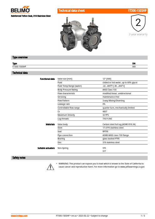
F7300-150SHP•Reinforced Teflon Seat, 316 Stainless SteelType overviewType DNF7300-150SHP300 Technical dataFunctional data Valve size [mm]12" [300]Fluid chilled or hot water, up to 60% glycolFluid Temp Range (water)-22...400°F [-30...204°C]Body Pressure Rating ANSI Class 150Flow characteristic modified linear, unidirectionalServicing maintenance-freeFlow Pattern3-way Mixing/DivertingLeakage rate0%Controllable flow range quarter turn, mechanically limitedCv4837Maximum Velocity32 FPSLug threads7/8-9 UNCMaterials Valve body Carbon steel full lug (ASME B16.34)Stem17-4 PH stainless steelSeat RPTFEPipe connection ASME/ANSI class 150 flangeBearing glass backed PTFEDisc316 stainless steelSuitable actuators Non-Spring SY5SY7Safety notesWARNING: This product can expose you to lead which is known to the State of California tocause cancer and reproductive harm. For more information go to F7300-150SHP Product featuresFlow/Mounting detailsDimensionsType DN WeightF7300-150SHP300661.4 lb [300 kg]SY4 (6)A B C D E F Number of Bolt Holes30.0" [762]24.7" [627]35.2" [893]25.6" [651]15.2" [387]12.0" [305]12F7300-150SHPA B C D E F Number of Bolt Holes31.5" [800]24.7" [627]38.7" [983]29.2" [742]15.2" [387]12.0" [305]12SY7-110On/Off, Floating point, Non fail-safe, 120 VTechnical dataElectrical data Nominal voltage AC 120 VNominal voltage frequency50/60 HzNominal voltage range AC 96...132 VTransformer sizing504 VACurrent consumption 4.2 AAuxiliary switch2x SPDT, 1 mA...5 A (3 A inductive), DC 5 V...AC250 V, 1 x 3° / 1 x 87°Switching capacity auxiliary switch 1 mA...5 A (3 A inductive), DC 5 V...AC 250 VElectrical Connection Terminal blocksOverload Protection thermally protected 135°C cut-outInternal Humidty Control resistive heating elementFunctional data Torque motor1000 NmDirection of motion motor selectable with switch 0/1Manual override hand wheelAngle of rotation90°Running Time (Motor)50 sDuty cycle value30%Noise level, motor45 dB(A)Position indication top mounted domed indicatorSafety data Degree of protection IEC/EN IP66/67Degree of protection NEMA/UL NEMA 4XEnclosure UL Enclosure Type 4XAgency Listing ISO, CE, cCSAusQuality Standard ISO 9001Ambient humidity Max. 100% RHAmbient temperature-22...149°F [-30...65°C]Storage temperature-40...176°F [-40...80°C]Servicing maintenance-freeWeight Weight46 lb [21 kg]Materials Housing material die cast aluminiumGear train high alloy steel gear sets, self lockingSY7-110ApplicationProduct featuresSY Series actuators are fractional horsepower devices, and utilize full-wave power supplies. Observe wire sizing and transformer sizing requirements. Proportional models CANNOT be connected to Belimo direct coupled (AF, AM, GM…etc) actuator power supplies or any type of half-wave device. You MUST use a separate, dedicated transformer or power supply to power the SY actuator. Please do not connect other automation equipment to the dedicated SY supply source. You MUST use four wires (plus a ground) to control a proportional control SY actuator (See SY Wiring Section).AccessoriesElectrical accessoriesDescriptionTypeLocal electric disconnect for SY4...12 series actuator, AC 120 V, on/off HOA-120VBattery backup system for SY7...12 series actuator, AC 120 V, on/offEXT-NSV-B05-120Electrical installationINSTALLATION NOTESDo not change sensitivity or dip switch setting with power applied.Power supply Common/Neutral and Control Signal "-"wiring to a common is prohibited.Terminals 4 and 6 need to be wired separately.Isolation relays must be used in parallel connection of multiple actuators using a commoncontrol signal inputs. The relays should be DPDT.Isolation relays are required in parallel applications. The reason parallel applications needisolation relays is that the motor uses two sets of windings, one for each direction. When one is energized to turn the actuator in a specific direction a voltage is generated in the other due to the magnetic field created from the first. It’s called back EMF. This is not an issue with one actuator because the voltage generated in the second winding isn’t connected to anything so there is no flow. On parallel applications without isolation, this EMF voltage energizes the winding it is connected to on the other actuators in the system, the actuators are tying to turn in both directions at once. The EMF voltage is always less than the supply voltage due to the resistance of the windings, so while the actuator still turns in the commanded direction, thedrag from the other reduces the torque output and causes overheating.Warning! Live electrical components!During installation, testing, servicing and troubleshooting of this product, it may be necessary to work with live electrical components. Have a qualified licensed electrician or other individual who has been properly trained in handling live electrical components perform these tasks. Failure to follow all electrical safety precautions when exposed to live electrical components could result in death or serious injury.SY7-110Wiring diagramsAC/DC 110/120 or 220/230VAC 110/120 or 220/230 VElectrical installation。
工业控制设备_UL508讲解(2)

第一篇 介绍UL
UL始建于1894年,初始阶段UL主要靠防火保险 部门提供资金维持动作,直到1916年,UL才完全自 立。经过近百年的发展,UL已成为具有世界知名度 的认证机构,其自身具有一整套严密的组织管理体 制、标准开发和产品认证程序。 UL主要从事产品的安全认证和经营安全证明业务, 其最终目的是为市场得到具有相当安全水准的商品, 为人身健康和财产安全得到保证作出贡献。目前, UL在美国本土有五个实验室,总部设在芝加哥北部 的Northbrook镇,同时在台湾和香港分别设立了相应 的实验室。
注:开放式—产品本身没有外壳,但可能后续会有一个密闭的外壳。其默认的防护等 级为1级,只能用于室内。
- Enclosed Type – Industrial control equipment provided with a suitably rated enclosure
注:封闭式---产品本身就能够提供一个具体一定防护等级的外壳
工业控制设备 ——UL508标准认证申请培训
Course Agenda主要培训内容 1.Introduction to UL(介绍UL) 2. Introduction to UL Certification Process ( UL产品审核流程介绍) 3.UL508涉及产品及其CCN 4.UL508概略介绍—术语和结构要求 5.Insulation System applied in UL508绝缘系统使用 6.电阻产品UL508认证要求 7.电抗产品UL508认证要求 8.Question&Answer
注:申请此环境温度进行测试,需要提供外壳进行测试(产品的1-1.5倍空间)
- A rating assigned to open type equipment that refers to the maximum ambient temperature of air immediately surrounding the equipment inside of the ultimate enclosure
超薄球阀
超薄球阀宝钢特种钢助推航天事业对于所有的中国人来说,神舟六号上天是件大喜事。
在宝钢集团上海五钢有限公司科技管理部的华文杰看来,这件事除了喜庆还多了点亲切感。
因为,在中国的载人航天飞船上就有宝钢生产的特种钢。
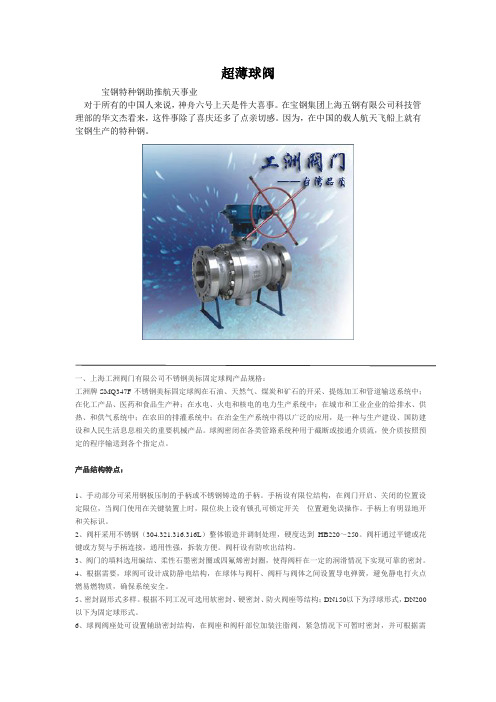
一、上海工洲阀门有限公司不锈钢美标固定球阀产品规格:工洲牌SMQ347F不锈钢美标固定球阀在石油、天然气、煤炭和矿石的开采、提炼加工和管道输送系统中;在化工产品、医药和食品生产种;在水电、火电和核电的电力生产系统中;在城市和工业企业的给排水、供热、和供气系统中;在农田的排灌系统中;在治金生产系统中得以广泛的应用,是一种与生产建设、国防建设和人民生活息息相关的重要机械产品。
球阀密闭在各类管路系统种用于截断或接通介质流,使介质按照预定的程序输送到各个指定点。
产品结构特点:1、手动部分可采用钢板压制的手柄或不锈钢铸造的手柄。
手柄设有限位结构,在阀门开启、关闭的位置设定限位,当阀门使用在关键装置上时,限位块上设有锁孔可锁定开关位置避免误操作。
手柄上有明显地开和关标识。
2、阀杆采用不锈钢(304.321.316.316L)整体锻造并调制处理,硬度达到HB220~250。
阀杆通过平键或花键或方契与手柄连接,通用性强,拆装方便。
阀杆设有防吹出结构。
3、阀门的填料选用编结、柔性石墨密封圈或四氟烯密封圈,使得阀杆在一定的润滑情况下实现可靠的密封。
4、根据需要,球阀可设计成防静电结构,在球体与阀杆、阀杆与阀体之间设置导电弹簧,避免静电打火点燃易燃物质,确保系统安全。
5、密封副形式多样。
根据不同工况可选用软密封、硬密封、防火阀座等结构;DN150以下为浮球形式,DN200以下为固定球形式。
6、球阀阀座处可设置辅助密封结构,在阀座和阀杆部位加装注脂阀,紧急情况下可暂时密封,并可根据需要加长阀杆以适宜埋地铺设得场所。
工洲牌不锈钢美标固定球阀主要连接尺寸:公称压力P N( Cl as s) 公称通径DNL d1DD1D2D6f f2 b Z-φd H1 H2RFBW全通径缩径15 0 L B 1/2181413-896.535- 2 - 12 4-15 - 593/411715219-98743- 2 - 12 4-15 - 63 112716525-1879.551- 2 - 12 4-15 - 7511/4141 -2 - 13 4-15 -11/21651938-12798.573- 2 - 15 4-15 - 95 217821651-15212.592- 2 - 16 4-19 - 10721/21924164-178139.515- 2 - 18 4-19 - 142 3 2 01512- 2 - 19 4-19 - 152. 54 22939.5157- 2 - 24 8-19 - 1785 3563811271 -2 - 24 8-22 - 2526 3944571.5216- 2 - 26 8-22 - 2728 4575212.527- 2 - 29 8-22 - 3981 -2 - 51 2 6183432381- 2 - 01 4 6867623373 - 2 - 51 6 7628383873375975447- 2 - 0 337635578533- 2 - 40 16-32 - -2 87699635584- 2 - 02 4 189813749.5692- 2 - 5030 0 L B 1/2141413-9566.535- 2 - 15 4-15 - 593/415215219-11782.43- 2 - 16 4-19 - 631 1651 -2 - 18 4-19 - 751 1 / 4 17817832-13398.564- 2 - 19 4-19 - -1 1 /2 191938-156114.573- 2 - 19 4-22 - 952 2162 2 - 2 - 23 8-19 - 1072 1 / 2 24125- 2 - 26 8-22 - 1423 283283766421168.5127- 2 - 29 8-22 - 1524 3 542157- 2 - 32 8-22 - 1785 3879235186- 2 - 35 8-22 - 2526 43457216- 2 - 37 12-22 - 2728 52521230 - 2 - 42 12-25 - 3981 03445387.5324- 2 - 51 2 6463338- 2 - 08 5 13 0 5 584514.5413- 2 - 51 6 838838387337648571.547- 2 - 0337711628.5533- 2 - 61 24-35 - -2 7 775686584- 2 - 02 4 11431143591483914813692- 2 - 5040 0 L B 1/2141413-9566.735-6.4-14.54-15 - 593/415215219-11782.543-6.4- 16 4-19 - 63 116516525-12488.951-6.4-17.54-19 - 7511/417817832-11/2191938-156114.373-6.4-22.54-22 - 952 2162 2 -6.4-25.58-19 - 1072 1 / 2 24124164-3 28328376644 3 542157-6.4- 35 8-26 - 1785 381381127126 434579.9216-6.4- 41.8 5 38133.227-6.4- 41 03445387.3324-6.4- 51 2 6486353.8381-6.4- 57.35585514.3413-6.4- 60.1 6 83883838733765571.547-6.4- 63.3372 87775685.8584-6.4- 02 4 11431143591483915812.8692-6.4- 76. 0公称压力PN(Class) 公称通径DNL d1D D1D2D6 f f2 bZZ-φdH1H2 RFBW全通径缩径600LB 1/216516513 - 9566.535- 6.4 - 154-15- 59 3/419119119 - 11882.543- 6.4 - 164-19- 63 12162 - 6.4 - 184-19- 75 11/422922932 - 13398.564- 6.4 - 214-19- - 11/224124138 -,, , , , ,156114.573- 6.4 - 234-22- 95 22922925 - 6.4 - 268-19- 107 21/2 3317915- 6.4 - 298-22- 178 335635676 64 210168.5127- 6.4 - 328-22- - 4432432157- 6.4 - 388-25- - 65595592216- 6.4 - 0 8666620 0 - 6.4 - 4 1 - 6.4 - 5 1283883829824855948938- 6.4 - 5114 889889327298603527413- 6.4 - 016 99199 0347- 6.4 - 518 1 27 743 654533- 6.4 - 02 3 375813724584- 6.4 - 8924-45- -900LB 236836847 38 216165.192-7.92-38.58-26- - 3 38190.5127123.827.92-41.58-29191259 445745798 73 292234.5157149.227.92-44.58-32216297 6 61 81317.5216211.127.92- 0 8737737190146470393.727269.887.92- 63.1 80 545459.5324323.857.92- 2 12965965282238610533.4381381.07.92- 79.1410291029- - - - -419.111.13- 5 1611301130- - - - -469.911.13- 2 1812191219- - - - -533.412.7- 1 6 2013341334- - - - -584.212.7- 1 41500LB 236836847 47 216165.112495.257.92-38.58-26126217 3 47203.2168136.927.92-456456498 98 311245.5194161.927.92-6 7 394317.5248211.129.52- 5 883283219019483393.7318269.8811.13- 5 1 38 565482.6371323.8511.13- 1 8 12 1 82 675571.5438381.014.27- 1 6 1412571257- - 826635489419.115.88-133.1613841384- - 915704.5546469.917.48-146.2016641664- - 1170990.6673584.217.48- 1 0一、产品[国际软密封球阀]的详细资料:产品型号:Q41F-16C产品名称:国际软密封球阀工洲牌产品特征适用介质:水、气、油品、天然气和酸碳腐蚀性介质适用温度:-196-350℃驱动方式:手动、气动、电动、波动等公称通径:DN15-250mm1/2″-10″ 国际软密封球阀价格,国际软密封球阀厂家,国际软密封球阀报价。
- 1、下载文档前请自行甄别文档内容的完整性,平台不提供额外的编辑、内容补充、找答案等附加服务。
- 2、"仅部分预览"的文档,不可在线预览部分如存在完整性等问题,可反馈申请退款(可完整预览的文档不适用该条件!)。
- 3、如文档侵犯您的权益,请联系客服反馈,我们会尽快为您处理(人工客服工作时间:9:00-18:30)。
DevicesAlGaAs Orange Red HER Green Package HDSP-HDSP-HDSP-HDSP- DescriptionDrawingA411A111A211A5117.6 mm Common Anode Right Hand Decimal A A413A113A213A5137.6 mm Common Cathode Right Hand Decimal B F411F111F211F51110 mm Common Anode Right Hand Decimal C F413F113F213F51310 mm Common Cathode Right Hand Decimal D G411G111G211G51110 mm Two Digit Common Anode Right Hand Decimal E G413G113G213G51310 mm Two Digit Common Cathode Right Hand Decimal F H411H111H211H51114.2 mm Common Anode Right Hand Decimal G H413H113H213H51314.2 mm Common Cathode Right Hand Decimal H K411K111K211K51114.2 mm Two Digit Common Anode Right Hand Decimal I K413K113K213K51314.2 mm Two Digit Common Cathode Right Hand DecimalJBlack Surface Seven Segment Displays Technical DataFeatures• Black Surface and Color Tinted Epoxy• Industry Standard Size • Industry Standard Pinout • Choice of Character Size 7.6 mm (0.30 in.), 10 mm (0.40in.), 14.2 mm (0.56 in.)• Choice of ColorsAlGaAs Red, High Efficiency Red (HER), Green, Orange • Excellent Appearance Evenly Lighted Segments ±50° Viewing Angle• Design FlexibilityCommon Anode or Common CathodeSingle and Two Digit• Categorized for Luminous IntensityCategorized for Color: Green Use of Like Categories Yields a Uniform Display• Excellent for Long Digit String MultiplexingDescriptionThese devices use industrystandard size package and pinout.Available with black surfaceHDSP-AX11/-AX13 Series HDSP-FX11/-FX13 Series HDSP-GX11/-GX13 Series HDSP-HX11/-HX13 Series HDSP-KX11/-KX13 Seriesfinish. All devices are available as either common anode or common cathode.Typical applications includeappliances, channel indicators of TV, CATV converters, game machines, and point of sale terminals.Part Numbering System5082 -X X X X-X X X X XHDSP-X X X X-X X X X XMechanical Options[1]00: No Mechanical OptionColor Bin Options[1,2]0: No Color Bin LimitationMaximum Intensity Bin[1,2]0: No Maximum Intensity Bin LimitationMinimum Intensity Bin[1,2]0: No Minimum Intensity Bin LimitationDevice Configuration/Color[1]1: Common Anode3: Common CathodeDevice Specific Configuration[1]Refer to Respective DatasheetPackage[1]A: 7.6 mm (0.3 inch) Single Digit Seven Segment DisplayF: 10 mm (0.4 inch) Single Digit Seven Segment DisplayG: 10 mm (0.4 inch) Dual Digit Seven Segment DisplayH: 14.2 mm (0.56 inch) Single Digit Seven Segment DisplayK: 14.2 mm (0.56 inch) Dual Digit Seven Segment Display Notes:1. For codes not listed in the figure above, please refer to the respective datasheet or contact your nearestAgilent representative for details.2. Bin options refer to shippable bins for a part number. Color and Intensity Bins are typically restricted to 1bin per tube (exceptions may apply). Please refer to respective datasheet for specific bin limit information.Package Dimensions (7.6 mm Series)Internal Circuit DiagramPackage Dimensions (10 mm Series: Single)Internal Circuit DiagramPackage Dimensions (10 mm Series: Two Digit)Internal Circuit DiagramPackage Dimensions (14.2 mm Series: Single)Internal Circuit DiagramPackage Dimensions (14.2 mm Series: Two Digit)Internal Circuit Diagram2DIGIT NO. 1 CATHODE1Absolute Maximum RatingsAlGaAs Red HER/Orange GreenHDSP-X11X HDSP-X21X/X41X HDSP-X51X Description Series Series Series Units Average Power per Segment37105105mW or DPPeak Forward Current per4590[1]90[3]mA Segment or DPDC Forward Current per15[5]30[2]30[4]mA Segment or DPOperating Temperature Range–20 to +100 –40 to +100°C Storage Temperature Range–55 to +100°C Reverse Voltage per 3.0V Segment or DPWave Soldering Temperature for250°C 3 Seconds (1.60 mm [0.063 in.]below Body)Notes:1. See Figure 5 to establish pulsed conditions.2. Derate above 53°C at 0.45 mA/°C (see Figure 7).3. See Figure 6 to establish pulsed conditions.4. Derate above 39°C at 0.37 mA/°C (see Figure 7).5. Derate above 91°C at 0.53 mA/°C (see Figure 1).Electrical/Optical Characteristics at T A = 25°CAlGaAs RedDevice SeriesHDSP-Parameter Symbol Min.Typ.Max.Units Test Conditions A11X Luminous Intensity/Segment[1,2]I V315600µcd I F = 1 mA (Digit Average)3600I F = 5 mAF11X, G11X330650I F = 1 mA3900I F = 5 mAH11X, K11X400700I F = 1 mA4200I F = 5 mAAll Devices Forward Voltage/Segment or DP V F 1.6 2.0V I F = 1 mA1.7I F = 5 mA1.822I F = 20 mA PeakPeak WavelengthλP EAK645nmDominant Wavelength[3]λd637nmReverse Voltage/Segment or DP[4]V R 3.015V I R = 100 µATemperature Coefficient of∆V F/°C-2mV/°CV F/Segment or DPA11X Thermal Resistance LED RθJ-PIN255°C/W/Junction-to-Pin Seg.F11X, G11X320H11X, K12X400OrangeDevice SeriesHDSP-Parameter Symbol Min.Typ.Max.Units Test Conditions A41X Luminous Intensity/Segment I V0.70mcd I F = 5 mA (Segment Average)[1,2]F41X, G41X 1.0I F = 5 mAH41X, K41X 2.37I F = 10 mAAll Forward Voltage/Segment or DP V F 2.0 2.5V I F = 20 mA DevicesPeak WavelengthλPEAK600nmDominant Wavelength[3]λd603nmReverse Voltage/Segment or DP[4]V R 3.030V I R = 100 µATemperature Coefficient of∆V F/°C–2mV/°CV F/Segment or DPA41X Thermal Resistance LED RθJ-PIN200°C/W/Junction-to-Pin Seg.F41X, G41X320H41X, K41X345High Efficiency RedDevice SeriesHDSP-Parameter Symbol Min.Typ.Max.Units Test Conditions A21X Luminous Intensity/Segment[1,2]I V360980µcd I F = 5 mA (Digit Average)5390I F = 20 mAF21X, G21X4201200I F = 5 mAH21X, K21X9002800I F = 10 mA3700I F = 60 mA Peak:1/6 Duty Factor All Forward Voltage/Segment or DP V F 2.0 2.5V I F = 20 mA DevicesPeak WavelengthλPEAK635nmDominant Wavelength[3]λd626nmReverse Voltage/Segment or DP[4]V R 3.030V I R = 100 µATemperature Coefficient of∆V F/°C-2mV/°CV F/Segment or DPA21X Thermal Resistance LED RθJ-PIN200°C/W/Junction-to-Pin Seg.F21X, G21X320H21X, K21X345High Performance GreenDevice SeriesHDSP-Parameter Symbol Min.Typ.Max.Units Test ConditionsA51X Luminous Intensity/Segment[1,2]I V8603000µcd I F = 10 mA (Digit Average)6800I F = 20 mAF51X, G51X10303500I F = 10 mAH51X, K51X9002500I F = 10 mA3100I F = 60 mA Peak:1/6 Duty FactorAll Forward Voltage/Segment or DP V F 2.1 2.5V I F = 10 mADevicesPeak WavelengthλPEAK566nmDominant Wavelength[3,5]λd571577nmReverse Voltage/Segment or DP[4]V R 3.050V I R = 100 µATemperature Coefficient of∆V F/°C-2mV/°CV F/Segment or DPA51X Thermal Resistance LED RθJ-PIN200°C/W/Junction-to-Pin Seg.F51X, G51X320H51X, G51X345Notes:1. Case temperature of device immediately prior to the intensity measurement is 25°C.2. The digits are categorized for luminous intensity. The intensity category is designated by a letter on the side of the package.3. The dominant wavelength, λd, is derived from the CIE chromaticity diagram and is that single wavelength which defines the color ofthe device.4. Typical specification for reference only. Do not exceed absolute maximum ratings.5. Green (HDSP-A51X/F51X/G51X/H512X/K51X) series displays are categorized for dominant wavelength. The category is designated bya number adjacent to the luminous intensity category letter.Figure 3. Relative Luminous Intensity vs. DC Forward Current.Figure 4. Relative Efficiency (LuminousIntensity per Unit Current) vs. Peak Current.Figure 1. Maximum Allowable Average orDC Current vs. Ambient Temperature.Figure 2. Forward Current vs. Forward Voltage.16024681012142010090807060504030T – AMBIENT TEMPERATURE – °C AI A V E . M A X – M A X I M U M A V E R A G E F O R W A R D C U R R E N T P E R S E G M E N T – m AF 1201102018F 50.020.010.05.02.01.00.50.10.51.01.52.02.5V – FORWARD VOLTAGE – VF I – F O R W A R D C U R R E N TP E R S E G M E N T – m A20105210.50.20.10.10.20.51251020R E L A T I V E L U M I N O U S I N T E N S I T Y (N O R M A L I Z E D T O 1 A T 1 m A )I – FORWARD CURRENT PER SEGMENT – mAF I – PEAK FORWARD CURRENTPER SEGMENT – mAPEAK η –R E L A T I V E E F F I C I E N C Y – N O R M A L I Z E D T O 1 A T 1 m AP E A K 1.31.21.11.00.90.80.7AlGaAs RedHER, Green, OrangeFigure 7. Maximum Allowable DCCurrent vs. Ambient Temperature.Figure 8. Forward Current vs.Forward Voltage Characteristics.Figure 9. Relative Luminous Intensity vs. DC Forward Current.Figure 10. Relative Efficiency (Luminous Intensity per Unit Current) vs. Peak Current.40051015202530352010090807060504030T – AMBIENT TEMPERATURE – °CA I M A X – M A X I M U M D C C U R R E N T P E R S E G M E N T – m AD C 1201105045010080604020I – F O R W A R D C U R R E N T P E R S E G M E N T – m AF 2.04.03.01.0V –FORWARD VOLTAGE – VF 05.0ηP E A K – R E L A T I V E L U M I N O U S I N T E N S I T Y (N O R M A L I Z E D T O 1 A T 5 m A F O R H E R ,A N D T O 1 A T 10 m A F O R G R E E N )150108642205301025I – FORWARD CURRENT PER SEGMENT – mAF 0I – PEAK FORWARD CURRENTPER SEGMENT – mAPEAK ηP E A K – R E L A T I V E E F F I C I E N C Y (N O R M A L I Z E D T O 1 A T 5 m A F O R H E R ,A N D 10 m A F O R G R E E N )Figure 5. Maximum Tolerable Peak Currentvs. Pulse Duration – HER, Orange.Figure 6. Maximum Tolerable Peak Current vs. Pulse Duration – Green.R A T I O O F M A X I M U M O P E R A T I N G P E A K C U R R E N T T O T E M P E R A T U R E D E R A T E D D C C U R R E N TI P E A K F I M A X D C t – PULSE DURATION – µsP 101100DC R A T I O O F M A X I M U M O P E R A T I N G P E A K C U R R E N T T O T E M P E R A T U R E D E R A T E D D C C U R R E N TI P E A K FI M A X D C t – PULSE DURATION – µs P 101100DCHDSP-A1xx IV Bin Category Min.Max.E 0.3150.520F 0.4280.759G 0.621 1.16H 0.945 1.71I 1.40 2.56J 2.10 3.84K 3.14 5.75L 4.708.55Intensity Bin Limits (mcd)AlGaAs RedHDSP-F1xx/G1xx IV Bin Category Min.Max.D 0.3910.650E 0.5320.923F 0.755 1.39G 1.13 2.08H 1.703.14HDSP-H1xx/K1xx IV Bin Category Min.Max.C 0.4150.690D 0.5650.990E 0.810 1.50F 1.20 2.20G 1.80 3.30H 2.73 5.00I 4.097.50OrangeHDSP-A41XIV Bin Category MinMaxA 0.2840.433B 0.3540.541C 0.4430.677D 0.5540.846E 0.692 1.057F 0.856 1.322G 1.082 1.652H 1.352 2.066I 1.692 2.581J 2.114 3.227K 2.641 4.034L 3.300 5.042M 4.127 6.303N 5.1577.878HDSP-F41X/G41XIV Bin Category MinMaxC 0.4850.890D 0.728 1.333E 1.091 2.000F 1.636 3.000G 2.454 4.500H 3.6826.751HDSP-H41X/K41XIV Bin Category MinMaxB 0.77 1.17C 0.95 1.45D 1.19 1.82E 1.49 2.27F 1.85 2.89G 2.32 3.54H 2.904.43Intensity Bin Limits (mcd), continued HERMin.Max.B0.3420.630C0.5160.946D0.774 1.418E 1.160 2.127F 1.740 3.190G 2.610 4.785H 3.9157.177Min.Max.C0.4850.890D0.728 1.333E 1.091 2.000F 1.636 3.000G 2.454 4.500H 3.682 6.751Min.Max.E0.91 1.67F 1.37 2.51G 2.05 3.76H 3.08 5.64I 4.628.64J 6.9312.70K10.3919.04Contrast EnhancementFor information on contrast enhancement, please see Application Note 1015.Soldering/CleaningFor information on soldering LEDs, please refer to Application Note 1029.Electrical/OpticalFor more information onelectrical/optical characteristics,please see Application Note 1005.Color CategoriesNote:All categories are established for classification of products. Products may not be available in all categories. Please contact your Agilent representatives for further clarification/information.HDSP-A5xx IV Bin Category Min.Max.H 0.86 1.58I 1.29 2.37J 1.94 3.55K 2.90 5.33L 4.378.01Intensity Bin Limits (mcd), continued GreenHDSP-F5xx/G5xx IV Bin Category Min.Max.H 1.54 2.82I 2.31 4.23J 3.46 6.34K 5.189.50L 7.7814.26HDSP-H5xx/K5xx IV Bin Category Min.Max.E 0.91 1.67F 1.37 2.51G 2.05 3.76H 3.08 5.64I 4.618.46/semiconductors For product information and a complete list of distributors, please go to our web site.For technical assistance call:Americas/Canada: +1 (800) 235-0312 or (916) 788-6763Europe: +49 (0) 6441 92460China: 10800 650 0017Hong Kong: (+65) 6756 2394India, Australia, New Zealand: (+65) 6755 1939 Japan: (+81 3) 3335-8152 (Domestic/Interna-tional), or 0120-61-1280 (Domestic Only) Korea: (+65) 6755 1989Singapore, Malaysia, Vietnam, Thailand, Philippines, Indonesia: (+65) 6755 2044 Taiwan: (+65) 6755 1843Data subject to change.Copyright © 2004 Agilent Technologies, Inc. Obsoletes 5988-1742ENJuly 17, 20045988-4433EN。