Digitally-Assisted Analog and RF CMOS Circuit Design for Software-Defined Radio
半导体测试原理

半导体测试公司简介Integrated Device Manufacturer (IDM):半导体公司,集成了设计和制造业务。
IBM:(International Business Machines Corporation)国际商业机器公司,总部在美国纽约州阿蒙克市。
Intel:英特尔,全球最大的半导体芯片制造商,总部位于美国加利弗尼亚州圣克拉拉市。
Texas Instruments:简称TI,德州仪器,全球领先的数字信号处理与模拟技术半导体供应商。
总部位于美国得克萨斯州的达拉斯。
Samsung:三星,韩国最大的企业集团,业务涉及多个领域,主要包括半导体、移动电话、显示器、笔记本、电视机、电冰箱、空调、数码摄像机等。
STMicroelectronics:意法半导体,意大利SGS半导体公司和法国Thomson半导体合并后的新企业,公司总部设在瑞士日内瓦。
是全球第五大半导体厂商。
Strategic Outsourcing Model(战略外包模式):一种新的业务模式,使IDM厂商外包前沿的设计,同时保持工艺技术开发Motorola:摩托罗拉。
总部在美国伊利诺斯州。
是全球芯片制造、电子通讯的领导者。
ADI:(Analog Devices, Inc)亚德诺半导体技术公司,公司总部设在美国,高性能模拟集成电路(IC)制造商,产品广泛用于模拟信号和数字信号处理领域。
Fabless:是半导体集成电路行业中无生产线设计公司的简称。
专注于设计与销售应用半导体晶片,将半导体的生产制造外包给专业晶圆代工制造厂商。
一般的fabless公司至少外包百分之七十五的晶圆生产给别的代工厂。
Qualcomm:高通,公司总部在美国。
以CDMA(码分多址)数字技术为基础,开发并提供富于创意的数字无线通信产品和服务。
如今,美国高通公司正积极倡导全球快速部署3G网络、手机及应用。
Broadcom:博通,总部在美国,全球领先的有线和无线通信半导体公司。
FPGA可编程逻辑器件芯片XC7VX690T-3FFG1926I中文规格书

Virtex-5 Family OverviewDS100 (v5.1) August 21, 2015Product SpecificationDigitally Controlled Impedance (DCI)Active I/O Termination•Optional series or parallel termination •Temperature and voltage compensation •Makes board layout much easier−Reduces resistors −Places termination in the ideal location, at the signalsource or destination Configuration •Support for platform Flash, standard SPI Flash, or standard parallel NOR Flash configuration •Bitstream support with dedicated fallback reconfiguration logic •256-bit AES bitstream decryption provides intellectual property security and prevents design copying •Improved bitstream error detection/correction capability •Auto bus width detection capability •Partial Reconfiguration via ICAP port Advanced Flip-Chip Packaging •Pre-engineered packaging technology for proven superior signal integrity−Minimized inductive loops from signal to return −Optimal signal-to-PWR/GND ratios •Reduces SSO induced noise by up to 7x •Pb-Free and standard packages System Monitor •On-Chip temperature measurement (±4°C)•On-Chip power supply measurement (±1%)•Easy to use, self-contained −No design required for basic operation −Autonomous monitoring of all on-chip sensors −User programmable alarm thresholds for on-chip sensors•User accessible 10-bit 200kSPS ADC −Automatic calibration of offset and gain error −DNL = ±0.9 LSBs maximum •Up to 17 external analog input channels supported −0V to 1V input range −Monitor external sensors e.g., voltage, temperature −General purpose analog inputs •Full access from fabric or JT AG TAP to System Monitor •Fully operational prior to FPGA configuration and during device power down (access via JTAG T AP only)65-nm Copper CMOS Process • 1.0V Core Voltage •12-layer metal provides maximum routing capability and accommodates hard-IP immersion •Triple-oxide technology for proven reduced static power consumption System Blocks Specific to the LXT, SXT, TXT, and FXT DevicesIntegrated Endpoint Block for PCI ExpressCompliance•Works in conjunction with RocketIO GTP transceivers (LXT and SXT) and GTX transceivers (TXT and FXT)to deliver full PCI Express Endpoint functionality withminimal FPGA logic utilization.•Compliant with the PCI Express Base Specification 1.1•PCI Express Endpoint block or Legacy PCI Express Endpoint block•x8, x4, or x1 lane width •Power management support •Block RAMs used for buffering •Fully buffered transmit and receive •Management interface to access PCI Express configuration space and internal configuration•Supports the full range of maximum payload sizes •Up to 6x 32 bit or 3x 64 bit BARs (or a combination of 32 bit and 64 bit)Tri-Mode Ethernet Media Access Controller •Designed to the IEEE 802.3-2002 specification •Operates at 10, 100, and 1,000 Mb/s •Supports tri-mode auto-negotiation •Receive address filter (5 address entries)•Fully monolithic 1000Base-X solution with RocketIO GTP transceivers •Supports multiple external PHY connections (RGMII,GMII, etc.) interfaces through soft logic and SelectIO resources •Supports connection to external PHY device through SGMII using soft logic and RocketIO GTP transceivers •Receive and transmit statistics available through separate interface •Separate host and client interfaces •Support for jumbo frames •Support for VLAN •Flexible, user-configurable host interface •Supports IEEE 802.3ah-2004 unidirectional modeVirtex-5 Family OverviewDS100 (v5.1) August 21, 2015Product Specification Table 1:Virtex-5 FPGA Family Members Device Configurable Logic Blocks (CLBs)DSP48E Slices (2)Block RAM Blocks CMTs (4)PowerPC Processor Blocks Endpoint Blocks for PCI ExpressEthernet MACs (5)Max RocketIO Transceivers (6)Total I/O Banks (8)Max User I/O (7)Array (Row x Col)Virtex-5 Slices (1)Max Distributed RAM (Kb)18Kb (3)36Kb Max (Kb)GTP GTX XC5VLX3080x 304,8003203264321,1522N/A N/A N/A N/A N/A 13400XC5VLX50120x 307,2004804896481,7286N/A N/A N/A N/A N/A 17560XC5VLX85120x 5412,96084048192963,4566N/A N/A N/A N/A N/A 17560XC5VLX110160x 5417,2801,120642561284,6086N/A N/A N/A N/A N/A 23800XC5VLX155160x 7624,3201,6401283841926,9126N/A N/A N/A N/A N/A 23800XC5VLX220160x 10834,5602,2801283841926,9126N/A N/A N/A N/A N/A 23800XC5VLX330240x 10851,8403,42019257628810,3686N/A N/A N/A N/A N/A 331,200XC5VLX20T60x 263,1202102452269361N/A 124N/A 7172XC5VLX30T80x 304,8003203272361,2962N/A 148N/A 12360XC5VLX50T120x 307,20048048120602,1606N/A 1412N/A 15480XC5VLX85T120x 5412,960840482161083,8886N/A 1412N/A 15480XC5VLX110T160x 5417,2801,120642961485,3286N/A 1416N/A 20680XC5VLX155T 160x 7624,3201,6401284242127,6326N/A 1416N/A 20680XC5VLX220T 160x 10834,5602,2801284242127,6326N/A 1416N/A 20680XC5VLX330T 240x 10851,8403,42019264832411,6646N/A 1424N/A 27960XC5VSX35T 80x 345,440520192168843,0242N/A 148N/A 12360XC5VSX50T 120x 348,1607802882641324,7526N/A 1412N/A 15480XC5VSX95T 160x 4614,7201,5206404882448,7846N/A 1416N/A 19640XC5VSX240T 240x 7837,4404,2001,0561,03251618,5766N/A 1424N/A 27960XC5VTX150T 200x 5823,2001,500804562288,2086N/A 14N/A 4020680XC5VTX240T 240x 7837,4402,4009664832411,6646N/A 14N/A 4820680XC5VFX30T 80x 385,12038064136682,4482114N/A 812360XC5VFX70T 160x 3811,2008201282961485,3286134N/A 1619640XC5VFX100T 160x 5616,0001,2402564562288,2086234N/A 1620680XC5VFX130T 200x 5620,4801,58032059629810,7286236N/A 2024840XC5VFX200T 240x 6830,7202,28038491245616,4166248N/A 2427960Notes:1.Virtex-5 FPGA slices are organized differently from previous generations. Each Virtex-5 FPGA slice contains four LUTs and four flip-flops (previously it was two LUTs and two flip-flops.)2.Each DSP48E slice contains a 25x 18 multiplier, an adder, and an accumulator.3.Block RAMs are fundamentally 36Kbits in size. Each block can also be used as two independent 18-Kbit blocks.4.Each Clock Management Tile (CMT) contains two DCMs and one PLL.5.This table lists separate Ethernet MACs per device.6.RocketIO GTP transceivers are designed to run from 100Mb/s to 3.75Gb/s. RocketIO GTX transceivers are designed to run from 150Mb/s to 6.5Gb/s.7.This number does not include RocketIO transceivers.8.Includes configuration Bank 0.。
IC资料-CD4501B资料
• 10% Tested for Quiescent Current at 20V
• Maximum Input Current of 1µA at 18V Over Full Package Temperature Range, 100nA at 18V and 25oC
DC Input Voltage Range . . . . . . . . . . . . . . . . . . -0.5V to VDD +0.5V DC Input Current, Any One Input. . . . . . . . . . . . . . . . . . . . . . ±10mA
76543210 4 2 5 1 12 15 14 13
TG
TG
TG
TG
TG
TG
TG
TG
COMMON OUT/IN
3
8 VSS
7 VEE
2
CD4051B, CD4052B, CD4053B
Functional Block Diagrams (Continued)
CD4052B
X CHANNELS IN/OUT 3210 11 15 14 12
15 2 14 1
X CHANNELS IN/OUT
13 COMMON “X” OUT/IN
12 0 11 3
X CHANNELS IN/OUT
10 A
9B
by 1 IN/OUT bx 2
cy 3 OUT/IN CX OR CY 4
IN/OUT CX 5 INH 6 VEE 7 VSS 8
16 VDD 15 OUT/IN bx OR by 14 OUT/IN ax OR ay 13 ay
600_electrical_engineering_books
這600本書幾乎包括了電氣工程專業的所有內容。
例如:電子學最基礎的《Circuit.Analysis.Theory.And.Practice.》(電路分析)、哈佛大學的經典教材《The.Art.of.Electronics》(電子學的藝術)、DSP.Facts.and.Equipment。
詳細書籍名:Wireless.Securit.PrivacyBest.Practices.and.Design.Techniques.Artech-Interference.Analysis.and.Reduction.for.Wireless.Systems.munications.works.munications.Network.Design._20-_20.Wiley._.Sons.802.11.Security.N.Fundamentals.Cisco.Press.eBookwork.Site.Surveying.and.Installation.Cisco.Press.Nov.2004.eBookA.First.Course.in.Corporate.Finance.b.in.Circuits.and.Electronics.munication.er_27s.Guide.to.Aspect.Ratio.Conversion.A.wavelet.tour.of.signal.processing.Mallat.S..draft_.2005.MNw.ponent.Modeling.Morgan.Kaufmann.eBook.-.LiB. Abstract.Harmonic.Analysis.of.Continuous.Wavelet.Transforms.Adaptive.Digital.Filters.Second.Edition.putational.Intelligence.Perspective.Adaptive_20Control_20Systems.Addison.Wesley._20-_20.RTP..Audio.and.Video.for.the.Internet.Advanced.Digital.Signal.Processing.and.Noise.Reduction.2nd.Edition.Advanced.Techniques.in.RF.Power.Amplifier.Design.works.Springer.eBook.Advanced_20Control_20Engineering.Advances.in.Fingerprint.Technology.Second.Edition.eBookworks.Artech.House.Publishers.Jun.2005.eBook. Aerials..Air.and.Spaceborne.Radar.Systems.An.Introduction.2001.WilliamAndrewPublishing.RR. munication.Systems.And.Their.Applications.Alternative.Breast.Imaging.Kluwer.Academic.Publishers.eBook.An.Introduction.To.Statistical.Signal.Processing.An.Introduction.to.Digital.Audio.An.Introduction.to.Pattern.Recognition.An_20Introduction_20to_20the_20Theory_20of_20Microwave_20Circuits_20_Kurokawa_. Analog.BiCMOS.Design.Practices.and.Pitfalls.Analog.Circuit.Design.Analog.Circuits.Cookbook.Analog.Integrated.Circuit.Design.Analog.and.Digital.Circuits.for.Electronic.Control.System.Applications..Analog_20And_20Digital_20Control_20System_20Design.Analysis.And.Design.Of.Analog.Integrated.Circuits.Analysis_20and_20Design_20of_20Integrated_20Circuit-Antenna_20Modules.Antenna_20Arraying_20Techniques_20In_20The_20Deep_20Space_20Network.Antenna_20handbook.rmation.Super.Skyways.Institute.of.Physics.Publishing.Feb.2004.eBook-DDU. Application.-.Specific.Integrated.Circuits.-.Addison.Wesley.Michael.John.Sebastian.Smith. munications.2002.Art.And.Business.Of.Speech.Recognition.Addison.Wesley.eBook.yout.Artech..Radio.Frequency.Integrated.Circuit.Design.Artech.House.GPRS.for.Mobile.Internet.rmation.theory.Asynchronous.Circuit.Design..Audel.Electrical.Course.for.Apprentices.and.Journeymen.eBook.Automated.Fingerprint.Identification.Systems..AFIS..Academic.Press.eBookAutomotive_20Computer_20Controlled_20Systems_20Diagnostic_20Tools_20And_20Techniques. Bandwidth.efficient.digital.modulation.in.deep.munications.ponents._.Hardware.-.I.CFS.ponents._.Hardware.-.II.CFS.Basic.Theory.and.Application.of.Transistors.Bebop.to.the.Boolean.Boogie.Bluetooth.Application.Developers.Guide.Bluetooth.Demystified.Bluetooth.Security.2004.BluetoothGuide.Broadband.Bible.John.Wiley.and.Sons.eBook.Broadband.Bringing.Home.the.Bits.Broadband.Microwave.Amplifiers.Artech.House.eBook-TLFeBOOK.Building.Financial.Models.McGraw-Hill.2004.works.with.802.11.eBook.C.Algorithms.for.Real._20-_20.time.DSP.1995.CAD_20of_20Microstrip_20Antennas_20for_20Wireless_20Applications.CDMA.Capacity.and.Quality.Optimization.CDMA.Mobile.Radio.Design.Artech.House.CDMA.RF.System.Engineering.CDMA.Systems.Capacity.Engineering.Artech.House.Publishers.eBook._20-_20.kB.CMOS.Analog.Circuit.Design.CMOS.Electronics.How.It.Works.How.It.Fails.yout.CMOS.Integrated.ADC.and.DAC.2ndEd..CMOS.PLL.Synthesizers.Analysis.and.Design.Springer.Nov.2004.eBook.-.LinG.CMOS.memory.circuits.CRC.Press.munications.Facility.Design.Handbook.CRC_20Press_20-_20Intelligent_20Control_20Systems_20Using_20Soft_20Computing_20Metho dologies.Cellular.Mobile.Radio.Systems.Designing.Systems.For.Capacity.Optimization.Circuit.-.techniques-for-low-voltage-high-speed-ADCs.Circuit.Analysis.Theory.And.Practice.Circuit.Design.for.RF.Transceivers.munications.Circuits.for.the.Hobbyist.Closed.Circuit.Television.Closing.The.Gap.Between.ASIC.and.Custom.Tools.And.Techniques.of.High.Performance.ASIC.Desig n.work.Test.and.Measurement.Handbook.works._20-_20.Fundamental.Concepts.-.McGraw.Hill.-.Leon-Garcia_.Widjaja. Communications.Receivers.DSP_.Software.Radios_.and.Design_.Third.Edition.Compact_20and_20Broadband_20Microstrip_20Antennas.Complete.Wireless.Design.Computer.Explorations.in.Signals.and.Systems.Computer.imaging.recipes.in.C.Myler.H.R._.Weeks.A.R..PH_.1993pi.T.munication.Consumer_27s.Guide.to.Cell.Phones.and.Wireless.Service.Plans.Continuous.-.Time.Active.Filter.Design.Control_20EngineeringGuide_20For_20Beginners.Coplanar_20Waveguide_20Circuits__20Components__20and_20Systems.Crane.R..Simplified.approach.to.image.processing.in.C.PH_.1997.T.ISBN.0132264161.DOE.Fundamentals.Handbook_.Electrical.Science.vol.1.DOE.Fundamentals.Handbook_.Electrical.Science.vol.2.DOE.Fundamentals.Handbook_.Electrical.Science.vol.3.DOE.Fundamentals.Handbook_.Electrical.Science.vol.4.DSP.Facts.and.Equipment.DSP.Realtime.Operating.Systems.for.Embedded.Systems.DSP.for.In.Vehicle.and.Mobile.Systems.Springer.eBook-YYePG.working.Devices._20-_20.Fourth.Edition.Data.Conversion.Handbook.Elsevier.eBook.-.LinG.Deep.Submicron.CMOS.Circuit.Design.Simulator.In.Hands.Delmar.Digital.Signal.Processing._20-_20.-Filtering.Approach.Delmar.Fiber.Optics.Technician_27s.Manual.2nd.Ed..Design.Of.Linear.RF.Outphasing.Power.Amplifiers.Artech.House.eBookNs.Springer.Sep.2005. Design.of.Analog.CMOS.Integrated.Circuits.Design_20of_20RF_20And_20Microwave_20Amplifiers_20And_20Oscillators..Designing.Analog.Chips.work.works.Developments.in.Speech.Synthesis.John.Wiley.Sons.Apr.2005.eBook._20-_20.LinG. Dictionary.of.Video.Television.Technology.Dielectric_20Resonator_20Antennas.Digital.Audio.Broadcasting.munication.Over.Fading.Channels.munications.Design.for.the.Real.World.Digital.Design.Fundamentals.Digital.Design.Principles.and.Practices.Digital.Electronics.Digital.Frequency.Synthesis.Demystified.Digital.Integrated.Circuits.wo02_8.munication.Digital.Logic.And.Microprocessor.Design.With.VHDL.Digital.Signal.Processing.Handbook.VK.Madisetti_DB.Williams_CRC.ing.C.bVIEW.Newnes.Jun.2005.eBook._20-_20.D DU.munications.Ieee.Digital.Switching.Systems.System.Reliability.and.Analysis.Digital.Synthesizers.and.Transmitters.for.Software.Radio.Springer.Jul.2005.eBook._20-_20.DDU. Digital.Systems.Engineering..Digital.Video.Quality.Vision.Models.and.Metrics.John.Wiley.and.Sons.Mar.2005.eBook._20-_20.D DU.Digital.Video.for.Dummies.Wiley..2003._.3Ed.Digital.image.processing._20-_20.B.Jahne.Digital.signal.Processing.Digitally.Assisted.Pipeline.ADCs.Theory.and.Implementation.Discovering.Bluetooth.Sybex.Discrete.Time.Signal.Processing._20-_20.Oppenheim.Distortion.Analysis.of.Analog.Integrated.Circuits.Distortion.in.rf.power.amplifiers.ebook._20-_20.lib.Duda.R.O._.Hart.P.E._.Stork.D.G..Pattern.classification.02ed._.Wiley.C.738s.EDGE.for.Mobile.Internet.ESD.In.Silicon.Integrated.Circuits.Electrical.Circuits.plante_CRC.Electrical._.Electronic.Principles._.Technology.-.0750665505.Newnes.John.Bird.Electrician_27s.Exam.Question.and.Answers.Electromagnetic_20Waves_20and_20Antennas.Electronics.for.Dummies.John.Wiley.and.Sons.eBook.-.LinG.Electronics.for.Hobbyists.1.Electronics.for.Hobbyists.2.Electronics.for.Hobbyists.3.Electronics.for.Hobbyists.4.Electronics.for.Hobbyists.5.Electronics.for.Hobbyists.6.Electronics.for.Hobbyists.7.work.Technologies.Springer.Sep.2004.eBook._20-_20.LinG. working.Engineer_27s.Mini.-._5bNotebook.-.555_5d.-.Timer.IC.Circuits.Engineer_27s.Notebook.II.A.Handbook.Of.Integrated.Circuit.Applications.-.Forrest.Mims. Engineering.Digital.Design.rmation.Theory.Error.control.coding..From.theory.to.practice.Sweeney.P..Wiley_2002.Essentials.of.Managing.Corporate.Cash.-.John.Wiley.Sons.Experimental.Approach.CDMA._.Interference.From.Architecture.Through.VLSI.Fast.Forward.MBA.in.Finance.Feedback.Amplifiers.Theory.and.Design.Feedback.Circuit.Analysis.Feedback.Linearization.of.RF.Power.Amplifiers.Feedbackcontroltheory.munication.Systems.Fiber.Optic.Sensors.Fiber.to.the.Home.The.New.Empowerment.Wiley.Interscience.Oct.2005.eBook._20-_20.LinG. Fibre.Channel.for.Mass.Storage._20-_20.Prentice.Hall.Fibre.Channel.for.SANs.Filter.Handbook.a.Practical.Design.Guide.-.S..Niewiadomski.Finance.for.Non.-.Financial.Managers.Financial.Engineering.Principles.A.Unified.Theory.Financial.Risk.Manager.Handbook.Wiley.Second.Edition.Financial.modeling.with.jump.processes.Finite_20Antenna_20Arrays_20and_20FSS.First.course.on.wavelets.Hernandez_.Weiss..CRC_.1996.T.ISBN.0849382742.Fixed.Broadband.Wireless.System.Design._20-_xxuss.For.Dummies.HDTV.For.Dummies.Nov.2004.eBook._20-_20.DDU.Fundamental_20Limitations_20In_20Filtering_20And_20Control.Fundamentals.Of.Electric.Circuits..Fundamentals.Of.RF.Circuit.Design.With.Low.Noise.Oscillators.munication.Fundamentals.of.Global.Positioning.System.Receivers.Fundamentals.of.Telecommunications.Fundamentals.of.wavelets..Theory_.algorithms_.and.applications.Goswami_.Chan..Wiley.T.319s. Fuzzy_20Control_20Systems_20-_20Design_20and_20Analysis.munications.works..Protocols.Terminology.and.Implementation.GSM.Switching.Services.and.Protocols.Getting.Started.As.a.Financial.Planner.Rev.and.Updated.Guide.To.Budgets.And.Financial.Management.Guide.To.Digital.Signal.Processing.HF_20Antenna_20Cookbook.HF_20Filter_20Design_20and_20Computer_20Simulation.Handbook.Of.Time.Series.Analysis_.Signal.Processing_.And.Dynamics.Handbook.of.Multisensor.Data.Fusion.puting.munications.works.Harjani.Design.Of.Modulators.For.Oversampled.Converters.Wang.-.1998.High.-.Speed.Signal.Propagation.Advanced.Black.Magic.Prentice.eBook-LiB.High.-.speed.Digital.Design.-.Johnson._.Graham.High.Frequency.Techniques.An.Introduction.to.RF.and.Microwave.Engineering.Wiley-IEEE.Press.. High_20Performance_20Control.IEE.Tutorial.Meeting.on.Digital.Signal.Processing.for.Radar.and.Sonar.Applications_.1990. IEEE.._20-_20..Telecommunications.Performance.Engineering.IEEE._20-_20.Adaptive.fuzzy.power.control.for.CDMA.mobile.radio.systems.IEEE._20-_work.Modeling_.Planning.and.Design.work.Design.Guide.IP.Routing.working_3b.Straight.to.the.Core.Ieee._20-_munication.Circuits.And.Systems.works.Springer.Sep.2005.eBook._20-_20.DDU. bVIEW.And.IMAQ.Vision.Prentice.eBook._20-_20.LiB.Image.Processing.in.C.Image.Recognition.and.Classification..algorithms-marcel.dekker.-.2002.-.isbn.0824707834.-.49. works.Newnes.Jul.2004.eBook._20-_20.DD U.Implementing.Bluetooth.in.an.Embedded.Device.Industrial.electronics.for.engineers_.chemists_.and.technicians.Industrial_20Control.Integrated.Electronics.Integrated.Fiber.Optic.Receivers.Buchwald.Intermodulation_20Distortion_20in_20Microwave_20and_20Wireless_20Circuits. Introduction.To.Error.Correcting.Codes.Introduction.To.Logic.Design.-.Shiva.S.G..-.M.Dekker.1998.2Ed.Introduction.To.Sound.Processing.work.Engineering.Introduction.to.03G_munications.Introduction.to.Airborne.Radar.Introduction.to.Bluetooth.Technology_.Market_.Operation_.Profiles_._.Services. Introduction.to.CPLD.and.FPGA.Design.Introduction.to.Fiber.Optics.Introduction.to.RF.Equipment.and.System.Design.Introduction.to.RF.Propagation.Wiley.Interscience.Sep.2005.eBook._20-_20.DDU. Introduction.to.Wireless.Local.Loop.Introduction_to_Wave_Propagation_Transmission_Lines_and_Antennas.John.Wiley.And.Sons.An.Introduction.To.Parametric.Digital.Filters.And.Oscillators.John.Wiley.And.Sons.Device.Modeling.For.Analog.And.RF.CMOS.Circuit.Design.John.Wiley.And.Sons.Digital.Logic.Testing.And.Simulation.John.Wiley._20-_20.Fundamentals.of.Digital.Television.Transmission.John.Wiley._20__20.Sons._20-_works.John.Wiley._20__20.Sons._20-_20.Mobile.and.Wireless.Design.Essentials.work.Design.Aug.2004.eBook._2 0-_20.DDU.John.Wiley.and.Sons.Multi.Carrier.and.Spread.Spectrum.Systems.works.Karu.J..Signals.and.systems_.made.ridiculously.simple.2001.L.T.ISBN.0964375214.Kay.S.M..Fundamentals.of.statistical.signal.processing...estimation.theory.PH.L.T.30.Ken.Martin.Digital.Integrated.Circuit.Design.300dpi.ponents.eBook.-.LiB. works.eBook._20-_20.LiB. Kluwer.Reuse.Methodology.Manual.for.System.-.on-a-Chip.Designs.3rd.Ed..LabVIEW.Digital.Signal.Processing.McGraw.Hill.Professional.May.2005.Layout.CMOS..Circuit.Design._.Li.Simulation.Baker._Boyce.-.1997.2.Linear_20Control_20System_20Analysis_20and_20Design_20Fifth_20Edition.Linear_20Optimal_20Control.Liquidity.Liabilities.Cash.Management.Balancing.Financial.Risks.Wiley.Low-Angle_Radar_Land_Clutter_-_Measurements_and_Empirical_Models.Lumped_20Elements_20for_20RF_20and_20Microwave_20Circuits.MPEG.7.Audio.and.Beyond.Audio.Content.Indexing.and.Retrieval.John.Wiley.and.Sons.Jan.2006. puter.Vision.Springer.Aug.2005.eBook._20-_20.DDU.McGraw.-.Hill.Teach.Yours.Electricity.and.ElectronicsEbook-FLY.McGraw.Hill.-.Principles.and.applications.of.Electrical.Engineering.McGraw.Hill.Financial.Analysis.Tools.and.Techniques.a.Guide.for.Managers.McGraw.Hill._20-_ponents.McGraw.Schaum_27s.Outlines.of.Digital.Signal.Processing.McGraw.Schaum_27s.Outlines.of.Signals._.Systems.McGraw._20-_20.Hill.-.Broadband.Crash.Course.-.2002.McGraw._20-_20.Hill.-.Wireless.A.to.Z.puter._20-_20._20T.266s_20.-.oriented.Approach.to.Pattern.Recognition.AP_.19 72.Microstrip_20Filters_20For_20RF_20Microwave_20Applications.Microwave_20Circuit_20Modeling_20Using_20Electromagnetic_20Field_20Simulation. Microwave_20Component_20Mechanics.Microwave_20Electronics_20Measurement_20and_20Materials_20Characterization. Microwave_20Resonators_20and_20Filters_20For_20Wireless_20Communication.Microwave_engineering_using_microstrip_circuits_.Microwaves.and.Wireless.Simplified.Artech.House.2nd.Edition.Apr.2005.Millimeter.-.wave.Integrated.Circuits.Springer.eBook-YYePG.Mixed.Signal.And.DSP.Design.Techniques.working._20-_20.John.Wiley._.Sons.-.IEEE.Press.munications.Engineering._20-_20.Theory.and.Applications_.Second.Edition. munications.Mobile.Location.Services.The.Definitive.Guide._20-_20.Prentice.Hall.works.Wiley._20-_20.eBOOK.Model.Based.Signal.Processing.Wiley.IEEE.Press.Oct.2005.eBook._20-_20.LinG.Modern.Antenna.Design.Jun.2005.eBook-DDU.munication.Circuits.Modern.Receiver.Front.Ends.Systems.Circuits.and.Integration.Wiley.Feb.2004.eBook-DDU. Modern.Signal.Processing.Modern_20Control_20Engeneering__203rd_20ed_5d._5bOgata_5d_5bPrentice_20Hall_5d. Morgan.Kaufmann.._20-_20..Digital.Video.And.Hdtv.Algorithms.And.Interfaces.2003.Multi.-.Standard.CMOS.Wireless.Receivers_.Analysis._.Design.Multicarrier.Techniques.for.04G_munications.Multivariable.Control.Systems.An.Engineering.Approach.Springer.eBook-TLFeBOOK.Nano.CMOS.Circuit.and.Physical.Design.Network.Calculus.A.Theory.of.Deterministic.Queuing.Systems.for.the.Internet.Networks_20and_20Devices_20Using_20Planar_20Transmissions_20Lines.Neural_20Systems_20For_20Control.New.technologies.for.WLAN.munications.Pocket.Book.Newnes.Guide.to.Television._.Video.Technology.Newnes.Radio.and.RF.Engineering.Pocket.Book.Newnes_20Industrial_20Control_20Wiring_20Guide.Next.Generation.Mobile.Systems.3G.and.Beyond.John.Wiley.and.Sons.May.2005.eBook._20-_20. DDU.Nixon_.Aguado..Feature.Extraction.and.Image.Processing.2002.Noise.In.Receiving.Systems.Nonlinear.Microwave.And.RF.Circuits.2nd.Edition.Nonlinear_20Microwave_20Circuit_20Design.ON.Analog.Integrated.Circuits.OReilly.Digital.Video.Hacks.May.2005.eBook._20-_20.DDU.OReilly.RFID.Essentials.Jan.2006.O_27Reilly._20-_20._20802._20-_works-.The.Definitive.Guide. Observers_20in_20Control_20Systems.Op.Amp.Applications..Op.Amps.Design.Application.and.Troubleshooting.Op.Amps.for.Everyone.Design.Reference.Operational.Amplifiers.Design.and.Applications.munications.Essentials.munications.Rules.of.Thumb.working.Handbook.Mcgraw._20-_20.Hill.Optical.System.Design.Optical.Through._20-_munications.Handbook.Optical.signal.processing.Vanderlugt.A..Wiley_.1991pi.L.T.180s.PEo.Optimal.Filtering.Optimal_20Control_20Linear_20Quadratic_20Methods.Optimal_20Sampled_20Data_20Control_20Systems.Optimizing.Wireless._20-_20.RF.Circuits.work.Handbook.Pattern.Classification.And.Learning.Theory.Lugosi.nguage.Processing.works.Polling_.Scheduling_.and.Traffic.Cont rol.munications.Phased.Array.Antenna.Handbook.Artech.House.Publishers.Second.Edition.eBook-kB.Phased_20Array_20Antennas_20Hansen_20R.C._20_Wiley_1998__ISBN_20047153076X__200dp i__T__504s__EE_.Photodetection._20__20.Measurement._20-_20.Maximizing.Performance.in.Optical.Systems. Practical.Analog.And.Digital.Filter.Design.Practical.Electronics.for.Inventors.Practical.FPGA.Programming.in.C.Prentice.Hall.PTR.Apr.2005.yout._20-_e.of.Stock.Lenses.Practical.Rf.Pcb.Design.Geoff.Smithson.Scanned.Practical.Rf.System.Design._20-_20.Egan.Practical_20Applications_20of_20Computational_20Intelligence_20for_20Adaptive_20Control. Practical_20Approach_20to_20Signals_20Systems_20and_20Control.Pragmatic.Introduction.to.Electronic.Engineering.0._v1_.works.John.Wiley.and.Sons.munication.system.simulation.with.wireless.applications._20-_20.Prentice.Hall. Principles.Of.Corporate.Finance.Principles.of.Asynchronous.Circuit.Design.-.A.Systems.Perspective.Principles.of.Digital.Transmission.With.Wireless.Applications.Principles.of.Sigma.Delta.Conversion.for.Analog.to.Digital.Converters.munication.Systems.eBook._20-_20.TLFeBOOK. Programmable.Digital.Signal.Processors.Architecture.Programming_.and.Applications. munication.System.Design.QoS.in.Integrated.03GNetworks.2002.Quantitative.Finance.for.Physicists.An.Introduction.Queueing.Theory.With.Applications.to.Packet.Telecommunication.Springer.eBook._20-_20.YYePG. RDS..The.Radio.Data.System.RF-Microwave_20Circuit_20Design_20for_20Wireless_20Applications.ponents.and.Circuits.munications.munications.RFID.Field.Guide.Deploying.Radio.Frequency.Identification.Systems.Feb.2005.eBook._20-_20.LiB. RFID.For.Dummies.Mar.2005.eBook._20-_20.LinG.RFID.Sourcebook.Prentice.Hall.PTR.RFID._20-_20.Read.My.Chips_.RF_20__20Microwave_20Radiation_20Safety_20Handbook.RF_20and_20Microwave_20Wireless_20Systems.Radar.Systems_.Peak.Detection.and.Tracking.Radar.Technology.Encyclopedia._20-_20.1998.Radar_20Principles.munication.and.Sensor.Applications.Radio.Engineers_27.Handbook._20-_20._2001e_20-_20.-.d.-.Terman.Radio.Frequency.Circuit.Design.Radio.Frequency.Transistors.Radio.Shack.-.Getting.started.in.electronics.Radio.Shack.Engineer_27s.Mini.-._5bNotebook.T.52s_5d.Radio._.Electronics.Cookbook.Radio_20Frequency_20and_20Microwave_20Communication_20Circuits.Radiometric.Tracking.Techniques.for.Deep.Space.Navigation.Radiosity.and.realistic.image.synthesis.Cohen.M.F._.Wallace.J.R..AP_.1995.Real.802.11.Security.Wi._20-_20.Fi.Protected.Access.And.802.11i.Addison.Wesley.eBook-LiB. Real.Analog.Solutions.for.Digital.Designers.Real.World.Digital.Audio.Peachpit.Press.No05._20v.200.Real._20-_pression--Techniques.And.Algorithms.Rf.Cmos.Power.Amplifier._20-_20.Ebook.Kluwer.Inter.Hella._.Ismall.Risk.Management.And.Capital.Adequacy.McGraw.Hill.SIP.Demystified.MUNICATIONS.HANDBOOK.munication.Engineering.eBook._20-_20.EEn.Satellite.Handbook.working.Principles.and.Protocols.John.Wiley.and.Sons.Oct.2005.eBook._20-_20.DDU. Schaums.Outline.Of.Theory.And.Problems.Of.Electric.Circuits.eBook.Secrets.of.RF.Circuit.Design._.Third.Edition.Securing.and.managing.WLAN.Shannon._20-_20.TheoryComm.munication.Fundamentals.of.RF.System.Design.and.Application. Signal.Analysis.Alfred.Mertins.Signal.Analysis.Time.Frequency.Scale.and.Structure.RL.Allen_ls.Signal.Detection.and.Estimation.munications.Handbook._20-_20.CRC.Press.-.2005.Signal.analysis.wavelets.filter.banks-Mertins.A..Wiley_.1999.Signals.And.Systems.Signals._20__20.Systems.with.MATLAB.Applications._20-_20.Orchard.Publications. munications.Sliding_20Mode_20Control_20in_20Engineering.Smart.Antennas.CRC.Press.Jan.2004.eBook-DDU.Some.Design.Aspects.on.RF.CMOS.LNAs.and.Mixers.Sonet.or.SDH.Demystified.Space._20-_20.Time.Coding.John.Wiley.And.Sons.eBook.Space._20-_munications.Specification.of.the.Bluetooth.System.Spectrum.Wars.Speech.Coding.Algorithms.Foundation.and.Evolution.of.Standardized.Coders.Wiley.eBook._20-_2 0.KB.works.Speech.Separation.By.Humans._20__20.Machines.Springer.eBook._20-_20.YYePG.Stability_20Analysis_20of_20Nonlinear_20Microwave_20Circuits.pression.to.Advanced.Video.Coding.IEEE.Standard.Handbook.of.Audio.and.Radio.Engineering.Standard.Handbook.of.Video.and.Television.Engineering_.4th.ed.Starting.Electronics.-.Elsevier.-.3rd.Edition.-.2005.Statistical.and.Adaptive.Signal.Processing.Supervised.and.Unsupervised.Pattern.Recognition.Synthesis.and.optimization.of.DSP.algorithms.Constantinides_.Cheung_.Luk..Kluwer_.2004.T.144s_20Bayesian.Approach.to.Image.Interpretation.Kopparapu_.Desai..Kluwer_.2002.T.181s_20Wavelets_.with.applications.in.signal.and.image.processing.Bultheel.A..2002.T.212s_20Brandwood..Fourier.transforms.in.radar.and.signal.processing.2003.T.359s_20Mann.S..Intelligent.image.processing.Wiley_.2002.T.406s_20Dudgeon.D._.Mersereau.R._.Merser.R._.Multidimensional.Digital.Signal.Processing.199 5.T.548s_20Ballard.D.H._.Computer.vision.Brown.C.M..PH_.1982.ISBN.0131653164.T.621s_20Image.analysis.and.mathematical.morphology.Serra.J..AP_.1982.300dpi.CsIp.TAB.Electronics.Guide.to.Understanding.Electricity.and.Electronics.eBook.-.EEn.Telecom.Crash.Course.Telecom.Dictionary.Telecommunication.Circuit.Design._20-_20.Second.Edition.Telecommunications.Essentials.CHM.Telecommunications.Regulation.Teletraffic.Engineering.Handbook.The.Art.and.Science.of.Analog.Circuit.Design.The.Art.of.Electronics.02ed.munications.Professional..A.Guide.for.Engineers.and.Managers. working.The.Engineer_27s.Guide.to.Decoding._.Encoding.The.Engineer_27s.Guide.to.Standards.Conversion.The.Great.Telecom.Meltdown.Artech.House.Jan.2005.eBook._20-_20.LiB.works.munications.Handbook.The.Mobile.Radio.Propagation.Channel._20-_20.Second.Edition.-.Wiley.The.Personal.Finance.Calculator.McGrawHill.munication.Applications.Handbook.The.Telecommunications.Handbook.The.Wireless.Data.Handbook._20-_20.Fourth.Edition.Thetrated.dictionary.of.electronics.Troubleshooting.Analog.Circuits.US.Navy._20-_20.Digital.Data.Systems.Ultra.Wideband.Radio.Technology.ing.Coded.Signals.Understanding.Cellular.Radio.munications.Understanding.Digital.Signal.Processing.Understanding.Digital.Terrestrial.Broadcasting.MAZ._20-_20.Artech.House. munications.Understanding.Telephone.Electronics.Understanding_20Microwaves_20_Scott_.rmation.Retrieval.IRM.eBook._20-_20.YYePG.Video.Demystified.A.Handbook.For.The.Digital.Engineer.munications.Voice.Over.802.11.W._20-_20._20for.03G_works.munications.System.Waveguide_20Handbook.Wavelets.For.Kids.A.Wavelets.For.Kids.B.Wideband.TDD.WCDMA.for.the.Unpaired.Spectrum.John.Wiley.Sons.May.2005.eBook._20-_20.Lin G.Wiley.-.Essentials.of.Financial.Analysis.Wiley._20-_works_.IP.and.the.Internet.-.Protocols_.Design.and.Operation.Wiley._20-_20.Digital.Image.Processing.WK.Pratt.-.Third.Edition.2001.munication.Systems._20-_20.Prentice.Hall.PTR.munication.Technologies.munication.Technology.munications.Wireless.Data.Demystified.McGraw.Hill.eBook._20-_20.LiB.Wireless.Data.Technologies.Reference.Handbook.John.Wiley.and.Sons.Wireless.Foresight.Scenarios.of.the.Mobile.World.in.2015.John.Wiley.and.Sons.eBook._20-_20.Li B.Wireless.Internet.Telecommunications.Artech.House.Publishers.eBook._20-_20.YYePG. working.with.ANSI._20-_20._2041__20-_20.-.Second.Edition.works.First._20-_20.Step..2005.munication.Systems.Springer.Verlag.Telos.Sep.2004.ISBN0387227849. Wireless.Technology.Protocols.Standards.and.Techniques.Young_.Gerbrands_.van.Vliet..Fundamentals.of.image.processing.Delft.U._.1998.T.11._5bT.270s_5dJohnson.D.H._.Wise.J.D..Fundamentals.of.electrical.engineering.1999._5bT.498s_5dGustafsson.F..Adaptive.Filtering.and.Change.Detection.Wiley_.2000._Delmar__20Modern_20Control_20Technology--Components_20__20Systems_20_2nd_20Ed._. dsp.algorithms.for.programmers.eWiley.Mobile.Fading.Channels._20-_20.-Modelling_.Analysis._.Simulation.electronics_20technician_20volume_201_20-_20safety.electronics_20technician_20volume_202_20-_20administration.electronics_20technician_20volume_203_20-_20communications_20systems.electronics_20technician_20volume_204_20-_20radar_20systems.electronics_20technician_20volume_206_20-_20digital_20data_20systems.electronics_20technician_20volume_207_20-_20antennas_20and_20wave_20propagation. low.power.asynchronous.DSP.numerical_20methods_20in_20electromagnetics.operational.amplifiers.-.2nd.edition.practical_aspects_of_feedback_control.structure.and.interpretation.of.signals.and.systems.下載地址:/file/f5ddfade86600_electrical_engineering_books.rar。
低噪放

(一) 国际发展现状
国际上的一些著名大学、研究机构以及 IC公司都己对多模多频段低噪声放大器的设 计做了广泛的研究,并且己经有了相当多的 成果。 2011年8月,日本的Lime Microsystems 公司推出了一款多模多频无线收发芯片 LMS6002,该芯片的工作频率为375MHz--4GHz,可用于3GPP ( WCDMA,HSPA和LTE), 3GPP2 (CDMA2000)以及WiMAX的应用上,其低噪声放大器的噪声系数不超过3dB。 2012年3月,富士通半导体公司推出了单芯片的2G13G/4G收发芯片MB86L1A,该芯 片支持LTE ( FDD和TDD), EDGE, EDGE-EVO, WCDMA,GSM, HSPA+, CDMA以及TD-SCDMA等多 种通信模式。 2013 年1 月,MTK 推出MT3332/MT3333 SoC(片上系统)芯片如图所示,可支持 GPS、北斗、GLONASS、伽利略及QZSS 等5 种全球卫星导航系统的信号,藉由多系统的 相互辅助,能大幅提升导航定位的精度和可靠性,避免误差随时间推移及行程增加而 累积。
传统的单频段LNA技术已趋于成熟,具有源级电感负 反馈结构的LNA由于其低噪声低功耗的特点而得到广泛应 用。 但是,面对多模多频段的需求,基于这种结构的LNA 设计遇到新的困难。首先,其窄带的输入阻抗匹配特点。 源级电感退化LNA输入阻抗只匹配在一个频点上,而多模 多频段需要低噪声放大器在多个频段都能实现匹配。虽然 二阶乃至高阶的输入阻抗匹配以及负载谐振网络能够支持 相隔比较远的两个或多个频带的低噪声放大,但是其在低 噪声放大方面的优势被削弱。
(一) 国际发展现状
2013 年11 月,高通与三星合作推出支持北斗卫星定位功能的旗舰智能手机 GALAXY Note 3(配备高通骁龙800 移动处理器MSM8974),成为首批支持北斗系统 的智能手机。 2013 年12 月,博通公司宣布推出一款支持北斗系统的卫星导航芯片BCM47531 (见图6),它能够同时使用从5 个卫星系统(GPS、GLONASS、QZSS、SBAS 和北斗 卫星)发出的信号来产生定位数据,提高 了导航定位精度,尤其是在性能受建筑和 掩体影响的城区,效果更为明显。 2014 年2 月,MTK 发布了全球首款支 持4G LTE 网片——MT6630,支持20/40/80 MHz 频道带宽,支持低功耗蓝牙,整合了 ANT +(蓝牙健康与健身聚合器套件)技 术,可广泛应用于运动健身配件/ 可穿戴 设备,同时支持GPS、北斗、GLONASS、 伽利略、QZSS 系统。
可变增益放大器VGA研究笔记

Performance summary of the proposed VGA
13
Proposed exponential function generator
It consists of a voltage-to-current converter (VIC), a linear current
减网络,构成VGA。
9
模拟和数字信号控制的比较
In general, digitally controlled VGAs use binary weighted arrays of resistors for gain variations and analog VGAs adopt a variable transconductance to control the gain. For a code division multiple access system requiring a power control range larger than 80dB, the VGA with continuously variable gains is preferred because it avoids signal phase discontinuity that is expected to cause problems, and it reduces the large number of control bits required with digitally controlled VGAs.
15
Linear current multiplier
I(T)是PATA电流,由于M1、M2与M3、M4的栅
极电压对应相等,则有(其中Itot是常数电流):
RS2253 三路双通道模拟多路复用 多路解复用 CMOS 电路芯片说明书

CMOS Triple 2-Channel Analog Multiplexer/DemultiplexerFEATURES•-3dB Bandwidth: 180MHz•Single Supply Operation +2.5V to +5.5V •Low ON Resistance, 48Ω(TYP) With 5V Supply•High Off-Isolation: -83dB (RL = 50Ω,f = 1MHz)•Break-Before-Make Switching•Binary Address Decoding on Chip •Operating Temperature Range:-40°C to +125°C•PACKAGES: SOIC-16(SOP16), SSOP-16, TSSOP-16 and QFN-3×3-16LAPPLICATIONS•Sensors•Analog and Digital Multiplexing and Demultiplexing•A/D and D/A Conversion•Signal Gating•Battery-Operated Equipment•Factory Automation•Appliances•Communications Circuits DESCRIPTIONThe RS2253 is a CMOS analog IC configured as three single-pole/double-throw (SPDT) switches. This CMOS device can operate from 2.5 V to 5.5 V.The RS2253 device are digitally-controlled analog switches. It has low on-resistance (48Ω TYP) and very low off-leakage current (1nA TYP).The RS2253 is available in Green SOIC-16, SSOP-16, TSSOP-16 and QFN-3×3-16L packages. It operates over an ambient temperature range of -40°C to +125°C.Functional Diagrams of RS2253PIN CONFIGURATIONS(TOP VIEW)SOIC-16(SOP16)/SSOP-16/TSSOP-16ENABLEYV CC X X1X0B CAXNC QFN-3×3-16LAX0X1(TOP VIEW)PIN DESCRIPTIONFUNCTION TABLEX=Don’t careNOTE: Input and output pins are identical and inter-changeable. Either may be considered an input or output; signals pass equally well in either direction.ABSOLUTE MAXIMUM RATINGS(1)V CC to GND..........................................................−0.3 to 6VInput Terminals, Voltage. (2) .................– 0.3 to (V+) + 0.3V Continuous Current into Any Terminal......................±20mAPeak Current, X_(Pulsed at 1ms,10% duty cycle)…………………….. ±40mA Storage Temperature ……….……………−65°C to +150°C Operating Temperature ……….…….……−40°C to +125°C Junction Temperature...............................................+150°C Package Thermal Resistance @ T A = +25°CQFN-3×3-16L………………….………..……………. 80°C/WSSOP-16……….…………........................................64°C/WSOIC-16, TSSOP-16………….……….…………….100°C/WLead Temperature (Soldering, 10s) …………….........260°CESD SusceptibilityHBM (1000V)MM (100V)(1) Stresses above these ratings may cause permanent damage. Exposureto absolute maximum conditions for extended periods may degradedevice reliability. These are stress ratings only, and functionaloperation of the device at these or any other conditions beyond thosespecified is not implied.(2) Input terminals are diode-clamped to the power-supply rails. Inputsignals that can swing more than 0.3V beyond the supply rails shouldbe current-limited to 10mA or less.PACKAGE/ORDERING INFORMATIONPRODUCT ORDERING NUMBER TEMPERATURERANGEPACKAGE LEADPACKAGEMARKINGPACKAGE OPTIONRS2253 RS2253XS16 -40°C ~+125°C SOIC-16(SOP16) RS2253 Tape and Reel,3000 RS2253XSS16 -40°C ~+125°C SSOP-16 RS2253 Tape and Reel,3000 RS2253XTSS16 -40°C ~+125°C TSSOP-16 RS2253 Tape and Reel,3000 RS2253XTQC16 -40°C ~+125°C QFN-3×3 -16L RS2253 Tape and Reel,3000ESD damage can range from subtle performancedegradation to complete device failure. Precisionintegrated circuits may be more susceptible todamage because very small parametric changescould cause the device not to meet its publishedspecifications.ESD SENSITIVITY CAUTIONELECTRICAL CHARACTERISTICSV CC = 5.0 V or 3.3V, FULL= –40°C to +125°C,Typical values are at TA = +25°C. (unless otherwise noted)(1) All unused digital inputs of the device must be held at V IO or GND to ensure proper device operation.ELECTRICAL CHARACTERISTICS (continued)V CC= 5.0 V or 3.3V, FULL= –40°C to +125°C Typical values are at TA = +25°C (unless otherwise noted)TYPICAL CHARACTERISTICSParameter Measurement InformationTest Circuit 1. Address Transition Times (t TRANS)Test Circuit 2. Switching Times (t ON, t OFF)Test Circuit 3. Break-Before-Make Time Delay (t D)Parameter Measurement Information (continued)Test Circuit 4. Charge Injection (Q)Test Circuit 5. Off Isolation, On LossTest Circuit 6. CapacitanceAPPLICATION NOTESThe RS2253 device is a triple 2-channel multiplexer having three separate digital control inputs, A, B, and C, and an inhibit input. Each control input selects one of a pair of channels which are connected in a single-pole, double-throw configuration.When the devices are used as demultiplexers, the CHANNEL IN/OUT terminals are the outputs and the COMMON OUT/IN terminals are the inputs.BINARY TO 1 OF 2Figure 1. The RS2253 Functional Block DiagramPACKAGE OUTLINE DIMENSIONSSOIC-16RECOMMENDED LAND PATTERN (Unit: mm)SSOP-16RECOMMENDED LAND PATTERN (Unit: mm)TSSOP-16RECOMMENDED LAND PATTERN (Unit: mm)QFN-3x3-16LSIDE VIEWTOP VIEW BOTTOM VIEW(Unit: mm)。
外文翻译---相控阵和雷达技术的突破

毕业设计(论文)外文文献翻译翻译(1)题目相控阵和雷达技术的突破翻译(2)题目发射KU-波段的相控阵天线在FSS通信系统中的应用学院电子信息学院专业英文译文1:相控阵和雷达技术的突破【摘要】许多人认为雷达是一个成熟的领域,不会发生任何新的变化,这种看法存在很久了,没有比这个看法更错误的了。
当我1950年参与到雷达领域的时候,我也有过同样的看法,例如,我认为麻省理工学院的雷达丛书已经是包罗万象了,不需要增加任何新的内容。
然而我是多么的错啊,从那时起雷达技术领域中已经发生了许多令人眼花缭乱的发展,雷达一直受益于Moore s定律和许多新的技术上的成果,例如,MMIC GaAs T/R组件和相控阵组件。
现在雷达技术发展得更快了,在这篇文章里,我将给出某些最近突破的例子。
【关键词】雷达;有源相控阵;MMIC;MEMS;T/R组件;相控阵;AESA;电扫;GaAs;GaN;SiC;CMOS;数字波束形成;自适应阵列;旁瓣对消器;超宽带天线;金属材料;电子管;真空电子器件;回旋管;磁控管;速调管;行波管;微波功率组件;MPM;功率放大组件;SBX;GBR—P0:SEA-BASED X-波段雷达24层楼高的SEA-BASED X-波段相控阵雷达是一个世界奇迹。
1:GaAs MMIC T/R模块(单片微波集成电路)在过去的十年成功和广泛的应用了MMIC和AESA(有源电子扫描阵)2:低成本¥19K AESA谁说AESA是非常昂贵的,在DARPA(Defense Advanced Research Projects Agency美国国防部先进研究项目局)的低资金¥19K资助下使35GHZ相控阵成为可能。
DARPA 已经资助发展了¥10 X-band,10’smW,单T/R芯片模块。
3:低成本的MEMS(微机电系统)相控阵即使我们只有一个低损耗的移相器,那么就能够用在一个模块上安装很多的移相而MEMS提供了这个可能。
数字化辅助的CBL在研究生正畸-正颌外科联合治疗教学中的应用

数字化辅助的CBL在研究生正畸-正颌外科联合治疗教学中的应用作者:胡芝爱邹淑娟祝颂松陈建伟来源:《中国美容医学》2024年第07期[摘要]目的:探討数字化辅助的案例教学法(Case-based learning,CBL)在研究生正畸-正颌外科联合治疗教学中的应用,以提供教学模式新思路。
方法:将30名口腔正畸专业一年级研究生随机分为两组,对照组采用PPT讲解知识点配合病例图片展示的传统教学模式,实验组在传统教学模式基础上增加三维数字化辅助的CBL教学,即在常规讲授教学前组织研究生学习三维数字化软件在正畸-正颌外科联合治疗典型病例中的应用。
采用随堂测验和问卷调查法对学生知识点掌握情况和教学满意度进行综合评价。
结果:随堂测验中,对照组得分为(9.87±1.71)分,实验组得分为(11.40±1.99)分,实验组对知识点的掌握情况显著优于对照组(P<0.05)。
两组学生在课前对此次课程的期待程度比较,差异无统计学意义(P>0.05),课程满意度综合评价中,实验组得分均显著高于对照组(P<0.05)。
结论:将三维数字化辅助的CBL教学模式应用于研究生正畸-正颌外科联合治疗教学,更能激发学生的学习兴趣,有助于学生在课堂上注意力的集中,使得教学内容更加容易理解,值得在正畸研究生教学中推广。
[关键词]数字化技术;案例教学法;正畸-正颌外科联合治疗;研究生教学;教学模式;教学质量[中图分类号]G642 [文献标志码]A [文章编号]1008-6455(2024)07-0156-04Application of Digitally Assisted CBL in the Teaching of Combined Orthodontic and Orthognathic Surgical Treatment for Postgraduate StudentsHU Zhiai1, ZOU Shujuan1, ZHU Songsong2, CHEN Jianwei1( 1.Department of Orthodontics, State Key Laboratory of Oral Diseases, National Clinical Research Center for Oral Diseases, West China Hospital of Stomatology, Chengdu 610041,Sichuan, China ; 2. Department of Orthognathic and Joint Surgery, West China Hospital of Stomatology, Sichuan University, Chengdu 610041, Sichuan, China )Abstract: Objective To explore the application of digitally assisted CBL in the teaching of combined orthodontics and orthognathic surgical treatment for postgraduate students, so as toprovide new ideas for the teaching model. Methods 30 first-year postgraduates majoring in orthodontics were randomly divided into two groups. In the control group, the traditional teaching mode of PPT with case pictures was used to explain the knowledge points. In the experimental group, digitally assisted CBL teaching was added to the traditional teaching mode, and the postgraduate students were organized to learn the application of 3D digital software in typical cases of combined orthodontic-orthognathic surgical treatment before the conventional lecture teaching. The students' knowledge and satisfaction of teaching were evaluated by means of a follow-up quiz and questionnaire. Results In the follow-up test, the score of the control group was (9.87±1.71)points, and the score of the experimental group was (11.40±1.99) points. The mastery of knowledge points in the experimental group was significantly better than that of the control group (P <0.05). There was no significant difference between the two groups in terms of students' expectations of this course before class (P>0.05). In the comprehensive evaluation of course satisfaction, the scores of the experimental group were significantly higher than those of the control group (P<0.05). Conclusion The application of digitally assisted CBL in the teaching of combined orthodontics and orthognathic surgical treatment for postgraduate students can better stimulate students' interest in learning, help them concentrate in class, and make the teaching content easier to be understood, which is worth promoting in orthodontic postgraduate teaching.Key words: digital technology; case-based learning; combined orthodontics and orthognathic surgical treatment; postgraduate teaching; teaching mode; teaching quality我国错牙合畸形发病率为67.82%,其中约5%为颌骨发育异常引起的牙颌面畸形[1]。
时间交织ADc

Bibliography[1] A.M.Abo,Design for reliability of low-voltage,switched-capacity circuits.Ph.D.Thesis,University of California,Berkeley,1999[2] A.M.Abo,P.R.Gray,A1.5-V,10-bit,14.3-MS/s CMOS pipeline analog-to-digital converter.IEEE J.Solid-State Circuits34(5),599–606(1999)[3] B.K.Ahuja,An improved frequency compensation technique for CMOS operational ampli-fiers.IEEE J.Solid-State Circuits18(6),629–633(1983)[4]V.J.Arkesteijn,Analog front-ends for software-defined radio receivers.Ph.D.dissertation,University of Twente,2007[5]V.J.Arkesteijn,E.A.M.Klumperink,B.Nauta,Jitter requirements of the sampling clock insoftware radio receivers.IEEE Trans.Circuits Syst.(TCAS)II53(2),90–94(2006)[6] C.W.Barbour,Simplified PCM analog to digital converter using capacity charge transfer,inProc.of the Telemetering Conf.(1971),pp.4.1–4.11[7] A.Barna,D.I.Porat,Integrated Circuits in Digital Electronics(Wiley,New York,1973),pp.353–354[8]W.C.Black,D.A.Hodges,Time interleaved converter arrays.IEEE J.Solid-State Circuits15(6),1022–1029(1980)[9]M.Boulemnakher,E.Andre,J.Roux,F.Paillardet,A1.2V4.5mW10b100MS/s pipelinedADC in65nm CMOS,in ISSCC Dig.Tech.Papers(2008),pp.250–251[10]T.B.Cho,P.R.Gray,A10b,20Msample/s,35mW pipeline A/D converter.IEEE J.Solid-State Circuits30(3),166–172(1995)[11]R.H.Dennard,F.H.Gaensslen,H.N.Yu,V.L.Rideovt,E.Bassous,A.R.LeBlanc,Design ofion-implanted MOSFET’s with very small physical dimensions.IEEE J.Solid-State Circuits 256–268(1974)[12]S.Devarajan,L.Singer,D.Kelly,S.Decker,A.Kamath,P.Wilkins,A16b125MS/s385mW78.7dB SNR CMOS pipeline ADC,in ISSCC Dig.Tech.Papers(2009),pp.86–87 [13] A.G.F.Dingwall,Monolithic expandable6bit20MHz CMOS/SOS A/D converter.IEEE J.Solid-State Circuits14(6),926–932(1979)[14]M.El-Chammas,B.Murmann,General analysis on the impact of phase-skew in time-interleaved ADCs,in IEEE International Symposium on Circuits and Systems(ISCAS) (2008),pp.17–20[15]S.L.J.Gierkink,Control linearity and jitter of relaxation oscillators.Ph.D.dissertation,Uni-versity of Twente,1999[16]S.K.Gupta,M.A.Inerfield,J.Wang,A1-GS/s11-bit ADC with55-dB SNDR,250-MAWpower realized by a high bandwidth scalable time-interleaved architecture.IEEE J.Solid-State Circuits41(12),2650–2657(2006)[17]K.Hadidi,A.Khoei,A highly linear cascode-driver CMOS source-follower buffer,in IEEEIntl.Conf.on Electronics,Circuits and Systems(1996),pp.1243–1246S.M.Louwsma et al.,Time-interleaved Analog-to-Digital Converters,131 Analog Circuits and Signal Processing,DOI10.1007/978-90-481-9716-3,©Springer Science+Business Media B.V.2011132Bibliography [18] C.-C.Hsu,F.-C.Huang,C.-Y.Shih,C.C.Huang,Y.-H.Lin,C.-C.Lee,B.Razavi,An11b800MS/s time-interleaved ADC with digital background calibration,in ISSCC Dig.Tech.Papers(2007),pp.464–465[19] E.Iroaga,B.Murmann,L.Nathawad,A background correction technique for timing errors intime-interleaved analog-to-digital converters,in IEEE International Symposium on Circuits and Systems(ISCAS),vol.6(2005),pp.5557–5560[20] E.A.M.Klumperink,B.Nauta,Systematic comparison of HF CMOS transconductors.IEEETrans.Circuits Syst.II,Analog Digit.Signal Process.50(20),728–741(2003)[21]N.Kurosawa,H.Kobayashi,K.Maruyama,H.Sugawara,K.Kobayashi,Explicit analysisof channel mismatch effects in time-interleaved ADC systems.IEEE Trans.Circuits Syst.I, Fundam.Theory Appl.48(3),261–271(2001)[22] F.Kuttner,A1.2V10b20MSample/s non-binary successive approximation ADC in0.13µmCMOS,in ISSCC Dig.Tech.Papers(2002),pp.176–177[23]Y.Z.Lin,S.J.Chang,Y.T.Liu,C.C.Liu,G.Y.Huang,A5b800MS/s2mW asynchronousbinary-search ADC in65nm CMOS,in ISSCC Dig.Tech.Papers(2009),pp.80–81 [24]S.M.Louwsma,E.J.M.van Tuijl,M.Vertregt,B.Nauta,A1.6GS/s,16times interleavedtrack&hold with7.6ENOB in0.12µm CMOS,in Proc.ESSCIRC(2004),pp.343–346 [25]S.M.Louwsma,E.J.M.van Tuijl,M.Vertregt,B.Nauta,A1.35GS/s,10b,175mW time-interleaved AD converter in0.13µm CMOS,in Proceedings of the Symposium on Very Large Scale Integration(VLSI)Circuits(2007),pp.62–63[26]S.M.Louwsma,E.J.M.van Tuijl,M.Vertregt,B.Nauta,A time-interleaved track&holdin0.13µm CMOS sub-sampling a4GHz signal with43dB SNDR,in Proceedings of the Custom Integrated Circuits Conference(CICC)(2007),pp.329–332[27]S.M.Louwsma,A.J.M.van Tuijl,M.Vertregt,B.Nauta,A1.35GS/s,10b,175mW time-interleaved AD converter in0.13µm CMOS.IEEE J.Solid-State Circuits43(4),778–786 (2008)[28]J.McCreary,P.Gray,All-MOS charge redistribution analog-to-digital conversion techniques.IEEE J.Solid-State Circuits10(6),371–379(1975)[29] E.Mensink,E.A.M.Klumperink,B.Nauta,Distortion cancellation by polyphase multipathcircuits.IEEE Trans.Circuits Syst.I,Regul.Pap.52(9),1785–1794(2005)[30]G.E.Moore,Cramming more components onto integrated circuits,in Electronics(1965),pp.114–2117[31] B.Murmann,A/D converter trends:power dissipation,scaling and digitally assisted architec-tures,in Proceedings of the Custom Integrated Circuits Conference(CICC),(2008),pp.751–758[32] B.Murmann,ADC Performance Survey1997–2009.Available online:http://www./~murmann/adcsurvey.html(2009)[33]K.Nagaraj, D.A.Martin,M.Wolfe,R.Chattopadhyay,S.Pavan,J.Cancio,T.R.Viswanathan,A dual-mode700-Msamples/s6-bit200-Msamples/s7-bit A/D converter in a0.25-µm digital CMOS process.IEEE J.Solid-State Circuits35(12),1760–1768(2000) [34]Y.Nakagome,H.Tanaka,K.Takeuchi,E.Kume,Y.Watanabe,T.Kaga,Y.Kawamoto,F.Murai,R.Izawa,D.Hisamoto,T.Kisu,T.Nishida,E.Takeda,K.Itoh,Experimental1.5-V 64-Mb DRAM.IEEE J.Solid-State Circuits26(4),465–472(1991)[35] B.Nauta,Analog CMOS low power design considerations,in Low Power Workshop on ES-SCIRC Conference(1996)[36] B.Nikoli´c,V.G.Oklobdžija,V.Stojanovi´c,W.Jia,J.K.S.Chiu,M.M.T.Leung,Improvedsense-amplifier-basedflip-flop:design and measurements.IEEE J.Solid-State Circuits35(6), 876–884(2000)[37]H.Pan,M.Segame,M.Choi,J.Cao,A.A.Abidi,A3.3-V12-b50-MS/s A/D converter in0.6-µm CMOS with over80-dB SFDR.IEEE J.Solid-State Circuits35,1769–1780(2000) [38]M.J.M.Pelgrom,A.C.J.Duinmaijer,A.P.G.Welbers,Matching properties of MOS transis-tors.IEEE J.Solid-State Circuits24(5),1433–1439(1989)Bibliography133 [39]K.Poulton,J.J.Corcoran,T.Hornak,A1-GHz6-bit ADC System.IEEE J.Solid-State Cir-cuits22(6),962–970(1987)[40]K.Poulton,R.Neff,B.Setterberg,B.Wuppermann,T.Kopley,R.Jewett,J.Pernillo,C.Tan,A.Montijo,A20GS/s8b ADC with a1MB memory in0.18µm CMOS,in ISSCC Dig.Tech.Papers(2003),pp.318–496[41] B.Razavi,Rf Microelectronics(Prentice Hall,New York,1998)[42] D.Schinkel,E.Mensink,E.A.M.Klumperink,A.J.M.van Tuijl,B.Nauta,A double-taillatch-type voltage sense amplifier with18ps setup+hold time,in ISSCC Dig.Tech.Papers (2007),pp.314–315[43] D.Schinkel,E.Mensink,E.A.M.Klumperink,A.J.M.van Tuijl,B.Nauta,A low-offsetdouble-tail latch-type voltage sense amplifier,in Proceedings of the18th ProRisc Workshop (2007)[44]H.Schmidt,Analog-Digital Conversion(Van Nostrand-Reinholt,New York,1970)[45] A.J.Scholten,G.D.J.Smit,B.A.D.Vries,L.F.Tiemeijer,J.A.Croon,D.B.M.Klaassen,R.van Langevelde,X.Li,W.Wu,G.Gildenblat,The new CMC standard compact MOS model PSP:advantages for RF applications,in IEEE Radio Frequency Integrated Circuits Symposium(2008),pp.247–250[46]T.Sepke,P.Holloway,C.G.Sodini,H.S.Lee,Noise analysis for comparator-based circuits.IEEE Trans.Circuits Syst.I,Regul Pap.56,541–553(2009)[47]R.C.Taft,P.A.Francese,M.R.Tursi,O.Hidri,A.MacKenzie,T.Hoehn,P.Schmitz,H.Werker,A.Glenny,A1.8V1.0GS/s10b self-calibrating unified-folding-interpolatingADC with9.1ENOB at Nyquist frequency,in ISSCC Dig.Tech.Papers(2009),pp.78–79 [48]H.P.Tuinhout,G.Hoogzaad,M.Vertregt,R.L.J.Roovers,C.Erdmann,Design and character-ization of a high precision resistor ladder test structure,in Proceedings of the IEEE Interna-tional Conference on Microelectronic Test Structures(ICMTS),vol.15(2002),pp.223–228 [49]R.C.H.van de Beek,High-speed low-jitter frequency multiplication in CMOS.Ph.D.disser-tation,University of Twente,2004[50]R.J.van de Plassche,Integrated Analog-to-Digital and Digital-to-Analog Converters(Kluwer Academic,Dordrecht,1994)[51]R.J.van de Plassche,R.E.J.van der Grift,A high-speed7bit A/D converter.IEEE J.Solid-State Circuits14(6),938–943(1979)[52]G.van der Plas,B.Verbruggen,A150MS/s133µW7b ADC in90nm digital CMOS using acomparator-based asynchronous binary-search sub-ADC,in ISSCC Dig.Tech.Papers(2008), pp.242–243[53]H.van der Ploeg,Calibration techniques in two-step a/d converters.Ph.D.dissertation,Uni-versity of Twente,2005[54]M.van Elzakker,A.J.M.van Tuijl,P.F.J.Geraedts,D.Schinkel,E.A.M.Klumperink,B.Nauta,A1.9µW4.4fJ/conversion-step10b1MS/s charge-redistribution ADC,in ISSCCDig.Tech.Papers(2008),pp.245–245[55] A.J.M.van Tuijl,personal communication[56] A.Verma,B.Razavi,A10b500MHz55mW CMOS ADC,in ISSCC Dig.Tech.Papers,(2009),pp.84–85[57]M.Vertregt,The analog challenge of nanometer CMOS,in International Electron DevicesMeeting(IEDM)(2006),pp.1–8[58]M.Vertregt,H.P.Tuinhout,personal communication[59]Video-transcript,Excerpts from a conversation with Gordon Moore:Moore’s law.ftp:///museum/Moores_Law/Video-Transcripts/Excepts_A_Conversation _with_Gordon_Moore.pdf(2005)[60]R.H.Walden,Analog-to-digital converter survey and analysis.IEEE J.Sel.Areas Commun.17(4),539–550(1999)[61] B.Wicht,T.Nirschl,D.Schmitt-Landsiedel,Yield and speed optimization of a latch-typevoltage sense amplifier.IEEE J.Solid-State Circuits39(7),1148–1158(2004)134Bibliography [62]Wikipedia,Orthogonal frequency-division multiplexing./wiki/Orthogonal_frequency-division_multiplexing(2009)[63]K.L.J.Wong,C.K.K.Yang,Offset compensation in comparators with minimum input-referred supply noise.IEEE J.Solid-State Circuits39(5),837–840(2004)[64]W.Yang,D.Kelly,L.Mehr,M.T.Sayuk,L.Singer,A3-V340-mW14-b75-Msample/sCMOS ADC with85-dB SFDR at Nyquist input.IEEE J.Solid-State Circuits36(12),1931–1936(2001)Index3D EM-field simulation,16AAD-Convertercounting,40flash,3,39,93folding,39pipeline,28,29,31,40,45,48,59,63–68, 93SA-ADC,40–57,91,94–108slope,40two-step,40amplifier,40,59,64,92,93,122interstage,108–111architectureTrack&Holdwith frontend sampler,17–20without frontend sampler,13–17Bbandwidthinput,16,19,30body effect,23bootstrapping,78–85bottom-plate sampling,6,28,29bufferbandwidth requirement,26distortion,23implementation,90input,14open-loop,22source follower,23,24,26,38,90,91Ccalibration,32–35,58,72,85,113,115,118 background,33bandwidth,12,22,35foreground,33gain,34,114offset,34,57,63,114,115timing,34,121,123 capacitancebuffer,input,25input,13,15–17interconnect,9capacitive load,26channel-charge injection,80,84,85 charge redistribution,27,83,110,111 clock feed-through,84,85clock generation,68,72,73,75,88,95 comparator,54–57,59,97,98Ddecoder,105digital control,40,41,94,99Eerrorgain,5offset,5timing,5Ffeedback,22Hhold-mode,5Jjitter,34–37,73,78,85,120,121,123S.M.Louwsma et al.,Time-interleaved Analog-to-Digital Converters,Analog Circuits and Signal Processing,DOI10.1007/978-90-481-9716-3,©Springer Science+Business Media B.V.2011135136IndexLladder connections,106layout,15,16,86,116look-ahead logic,53,99,101,103Mmatchingcapacitor,10Miller effect,25,109mismatchbandwidth,9–12between channels,6gain,6,7offset,6timing,6Nnoiseamplifier,64kT/C,16,58–61,64,85,111variance,59,64–66non-interleaved,5,6,22,26,30,39,68Ooffsetchannel,6comparator,57opamp,28,29,31,57,58,63,67,91,93,104, 108,109Pphase-differences,8Rreliability,79,82,83reset switch,15resistanceinterconnect,9switch,9,10,19,51,79Ssettling,14settling time,19,28,41–44,48,49single-sided overrange technique,46,47,49, 94,99,101spectrum,6spurious tones,6switchto avoid distortion,27switch-driver,85Ttechnology,10,14,16,19,22,32timing-misalignment,8,17Track and Holdbuffer,22–28track-mode,5track-timereduction,14,18track-time reduction,29 transconductance amplifier,59 transmission lines,13。
CD4052BMS中文资料
BINARY TO
1 OF 4 DECODER
WITH INHIBIT
TG
COMMON X
OUT/IN
TG
13
TG
3
COMMON Y
TG
OUT/IN
*
INH 6
8 VSS
LOGIC LEVEL CONVERSION
*
A 11
*
B 10
*
C9
*
INH 6
TG
7 VEE
TG 1524 0123 Y CHANNELS IN/OUT
H1E
H6W
†CD4052B, CD4053 Only
• Analog and Digital Multiplexing and Demultiplexing
• A/D and D/A Conversion
• Signal Gating
* When these devices are used as demultiplexers the “CHANNEL IN/OUT” terminals are the outputs and the “COMMON OUT/IN” terminals are the inputs.
AD5449资料
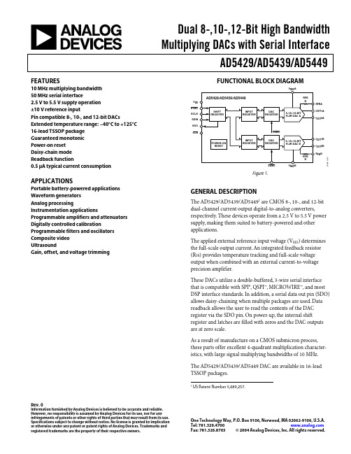
Dual 8-,10-,12-Bit High BandwidthMultiplying DACs with Serial InterfaceAD5429/AD5439/AD5449 Rev.0Information furnished by Analog Devices is believed to be accurate and reliable.However, no responsibility is assumed by Analog Devices for its use, nor for anyinfringements of patents or other rights of third parties that may result from its use. Specifications subject to change without notice. No license is granted by implication or otherwise under any patent or patent rights of Analog Devices. Trademarks and registered trademarks are the property of their respective owners.One Technology Way, P.O. Box 9106, Norwood, MA 02062-9106, U.S.A. Tel: Fax: 781.326.8703© 2004 Analog Devices, Inc. All rights reserved.FEATURES10 MHz multiplying bandwidth50 MHz serial interface2.5 V to 5.5 V supply operation±10 V reference inputPin compatible 8-, 10-, and 12-bit DACs Extended temperature range: −40°C to +125°C 16-lead TSSOP packageGuaranteed monotonicPower-on resetDaisy-chain modeReadback function0.5 µA typical current consumption APPLICATIONSPortable battery-powered applications Waveform generatorsAnalog processingInstrumentation applications Programmable amplifiers and attenuators Digitally controlled calibration Programmable filters and oscillators Composite videoUltrasoundGain, offset, and voltage trimmingFUNCTIONAL BLOCK DIAGRAMSYNCSCLKSDINI OUT1BI OUT1AR FB AI OUT2AI OUT2B4464--1V DDR FB BSDOFigure 1.GENERAL DESCRIPTIONThe AD5429/AD5439/AD54491 are CMOS 8-, 10-, and 12-bit dual-channel current output digital-to-analog converters, respectively. These devices operate from a 2.5 V to 5.5 V power supply, making them suited to battery-powered and other applications.The applied external reference input voltage (V REF) determines the full-scale output current. An integrated feedback resistor (R FB) provides temperature tracking and full-scale voltage output when combined with an external current-to-voltage precision amplifier.These DACs utilize a double-buffered, 3-wire serial interface that is compatible with SPI®, QSPI™, MICROWIRE™, and most DSP interface standards. In addition, a serial data out pin (SDO) allows daisy-chaining when multiple packages are used. Data readback allows the user to read the contents of the DAC register via the SDO pin. On power-up, the internal shift register and latches are filled with zeros and the DAC outputs are at zero scale.As a result of manufacture on a CMOS submicron process, these parts offer excellent 4-quadrant multiplication character-istics, with large signal multiplying bandwidths of 10 MHz. The AD5429/AD5439/AD5449 DAC are available in 16-lead TSSOP packages.1 US Patent Number 5,689,257.AD5429/AD5439/AD5449Rev. 0 | Page 2 of 32TABLE OF CONTENTSSpecifications.....................................................................................3 Timing Characteristics.....................................................................5 Absolute Maximum Ratings............................................................7 ESD Caution..................................................................................7 Pin Configuration and Function Descriptions.............................8 Terminology......................................................................................9 Typical Performance Characteristics...........................................10 General Description.......................................................................15 Unipolar Mode............................................................................15 Bipolar Operation.......................................................................16 Stability........................................................................................16 Single-Supply Applications........................................................17 Positive Output Voltage.............................................................17 Adding Gain................................................................................18 Divider or Programmable Gain Element................................18 Reference Selection....................................................................19 Amplifier Selection....................................................................19 Serial Interface................................................................................20 Microprocessor Interfacing.......................................................22 PCB Layout and Power Supply Decoupling................................24 Power Supplies for the Evaluation Board................................24 Evaluation Board for the DACs................................................24 Overview of AD54xx Devices.......................................................28 Outline Dimensions.......................................................................29 Ordering Guide.. (29)REVISION HISTORY7/04—Revision 0: Initial VersionAD5429/AD5439/AD5449SPECIFICATIONSV DD = 2.5 V to 5.5 V, V REF = 10 V, I OUT2A, I OUT2B = 0 V. All specifications T MIN to T MAX, unless otherwise noted. DC performance measured with OP1177, ac performance with AD9631, unless otherwise noted. Temperature range for Y version is −40°C to +125°C.Table 1.Parameter Min Typ Max Unit ConditionsSTATIC PERFORMANCEAD5429Resolution 8 BitsRelative Accuracy ±0.5 LSBDifferential Nonlinearity ±1 LSB Guaranteed monotonicAD5439Resolution 10 BitsRelative Accuracy ±0.5 LSBDifferential Nonlinearity ±1 LSB Guaranteed monotonicAD5449Resolution 12 BitsRelative Accuracy ±1 LSBDifferential Nonlinearity −1/+2 LSB Guaranteed monotonicGain Error ±10 mVGain Error Temp Coefficient1±5 ppm FSR/°COutput Leakage Current ±5 nA Data = 0000H, T A = 25°C, I OUT1±10 nA Data = 0000H, I OUT1REFERENCE INPUT1Typical resistor TC = −50 ppm/°C Reference Input Range ±10 VV REF A,V REF B Input Resistance 8 10 12 kΩ DAC input resistanceV REF A/B Input Resistance Mismatch 1.6 2.5 % Typ = 25°C, max = 125°CDIGITAL INPUTS/OUTPUT1Input High Voltage, V IH 1.7 V V DD = 2.5 V to 5.5 VInput Low Voltage, V IL0.8 V V DD = 2.7 V to 5.5 V0.7 V V DD = 2.5 V to 2.7 VInput Leakage Current, I IL 1 µAInput Capacitance 10 pFV DD = 4.5 V to 5.5 VOutput Low Voltage, V OL0.4 V I SINK = 200 µAOutput High Voltage, V OH V DD − 1 V I SOURCE = 200 µAV DD = 2.5 V to 3.6 VOutput Low Voltage, V OL0.4 V I SINK = 200 µAOutput High Voltage, V OH V DD − 0.5 V I SOURCE = 200 µADYNAMIC PERFORMANCE1Reference Multiplying BW 10 MHz V REF = 5 V p-p, DAC loaded all 1sOutput Voltage Settling Time Measured to ±4 mV of FS, R LOAD = 100 Ω,C LOAD = 0sAD5429 50 100 nsAD5439 55 110 ns DAC latch alternately loaded with 0sand 1sAD5449 90 160 ns R LOAD = 100 Ω, C LOAD = 15 pFDigital Delay 20 40 nsDigital-to-Analog Glitch Impulse 3 nV-s 1 LSB change around major carry,V REF = 0 VMultiplying Feedthrough Error −75 dB DAC latch loaded with all 0s,reference = 10 kHzRev. 0 | Page 3 of 32AD5429/AD5439/AD5449Rev. 0 | Page 4 of 32ParameterMin Typ Max Unit ConditionsOutput Capacitance 2 pF DAC latches loaded with all 0s4 pF DAC latches loaded with all 1sDigital Feedthrough 5 nV-sFeedthrough to DAC output with CS high and alternate loading of all 0s and all 1s Total Harmonic Distortion −75 dB V REF = 5 V p-p, all 1s loaded, f = 1 kHz−75 dBV REF = 5 V, sine wave generated from digital code Output Noise Spectral Density 25 nV/√Hz@ 1 kHzSFDR PERFORMANCE (Wideband) AD5449, 65 k codes, V REF = 3.5 V Clock = 10 MHz 500 kHz fout 55 dB 100 kHz fout 63 dB 50 kHz fout 65 dB Clock = 25 MHz 500 kHz fout 50 dB 100 kHz fout 60 dB 50 kHz fout 62 dBSFDR PERFORMANCE (Narrow Band) AD5449, 65 k codes, V REF = 3.5 V Clock = 10 MHz 500 kHz fout 73 dB 100 kHz fout 80 dB 50 kHz fout 87 dB Clock = 25 MHz 500 kHz fout 70 dB 100 kHz fout 75 dB 50 kHz fout 80 dBINTERMODULATION DISTORTION AD5449, 65 k codes, V REF = 3.5 V Clock = 10 MHz f 1 = 400 kHz, f 2 = 500 kHz 65 dB f 1 = 40 kHz, f 2 = 50 kHz 72 dB Clock = 25 MHz f 1 = 400 kHz, f 2 = 500 kHz 51 dB f 1 = 40 kHz, f 2 = 50 kHz 65 dB POWER REQUIREMENTS Power Supply Range 2.5 5.5 VI DD 10 µALogic inputs = 0 V or V DD Power Supply Sensitivity 10.001 %/%∆V DD = ±5%1Guaranteed by design and characterization, not subject to production test.AD5429/AD5439/AD5449TIMING CHARACTERISTICSV DD = 2.5 V to 5.5 V, V REF = 5 V, I OUT2 = 0 V. All specifications T MIN to T MAX, unless otherwise noted.See Figure 2 and Figure 3. Temperature range for Y version is −40°C to +125°C. Guaranteed by design and characterization, not subject to production test. All input signals are specified with tr = tf = ns (10% to 90% of V DD) and timed from a voltage level of (V IL + V IH)/2.1 Falling or rising edge as determined by the control bits of the serial word. Strong or weak SDO driver selected via the control register.2 Daisy-chain and readback modes cannot operate at maximum clock frequency. SDO timing specifications are measured with a load circuit, as shown in Figure 4.Rev. 0 | Page 5 of 32AD5429/AD5439/AD5449Rev. 0 | Page 6 of 32SCLKDINLDAC 12NOTES1ASYNCHRONOUS LDAC UPDATE MODE 2ALTERNATIVELY, DATA CAN BE CLOCKED INTO INPUT SHIFT REGISTER ON RISING EDGE OF SCLK AS DETERMINED BY CONTROL BITS. TIMING AS ABOVE, WITH SCLK INVERTED.04464-0-002Figure 2. Standalone Mode Timing Diagram04464-0-003SCLKSYNCSDINSDOALTERNATIVELY, DATA CAN BE CLOCKED INTO INPUT SHIFT REGISTER ON RISING EDGE OF SCLK AS DETERMINED BY CONTROL BITS. IN THIS CASE, DATA WOULD BE CLOCKED OUT OF SDO ON FALLING EDGE OF SCLK. TIMING AS ABOVE, WITH SCLK INVERTED.Figure 3. Daisy-Chain and Readback Modes Timing DiagramPINFigure 4. Load Circuit for SDO Timing SpecificationsAD5429/AD5439/AD5449Rev. 0 | Page 7 of 32ABSOLUTE MAXIMUM RATINGSTable 3.Parameter RatingV DD to GND −0.3 V to +7 VV REF , R FB to GND −12 V to +12 VI OUT 1, I OUT 2 to GND −0.3 V to +7 VInput Current to Any Pin except Supplies ±10 mALogic Inputs and Output 1−0.3 V to V DD + 0.3 VOperating Temperature RangeExtended (Y Version)−40°C to +125°C Storage Temperature Range −65°C to +150°C Junction Temperature150°C 16-Lead TSSOP θJA Thermal Impedance 150°C/W Lead Temperature, Soldering (10 s) 300°C IR Reflow, Peak Temperature (< 20 s)235°C1Overvoltages at SCLK, SYNC , and DIN are clamped by internal diodes. Current should be limited to the maximum ratings given.Stresses above those listed under Absolute Maximum Ratings may cause permanent damage to the device. This is a stress rating only; functional operation of the device at these or any other conditions above those listed in the operational sections of this specification is not implied. Exposure to absolute maximum rating conditions for extended periods may affect device reliability. Only one absolute maximum rating may be applied at any one time. Transient currents of up to 100 mA do not cause SCR latch-up. T A = 25°C unless otherwise noted.ESD CAUTIONESD (electrostatic discharge) sensitive device. Electrostatic charges as high as 4000 V readily accumulate on the human body and test equipment and can discharge without detection. Although this product features proprietary ESD protection circuitry, permanent damage may occur on devices subjected to high energy electrostatic discharges. Therefore, proper ESD precautions are recommended to avoid performancedegradation or loss of functionality.AD5429/AD5439/AD5449Rev. 0 | Page 8 of 32PIN CONFIGURATION AND FUNCTION DESCRIPTIONSNC = NO CONNECT04464-0-005Figure 5. Pin ConfigurationAD5429/AD5439/AD5449Rev. 0 | Page 9 of 32TERMINOLOGYRelative AccuracyRelative accuracy or endpoint nonlinearity is a measure of the maximum deviation from a straight line passing through the endpoints of the DAC transfer function. It is measured after adjusting for zero and full scale and is typically expressed in LSBs or as a percentage of full-scale reading.Differential NonlinearityDifferential nonlinearity is the difference between the measured change and the ideal 1 LSB change between any two adjacent codes. A specified differential nonlinearity of ±1 LSB maximum over the operating temperature range ensures monotonicity. Gain ErrorGain error or full-scale error is a measure of the output error between an ideal DAC and the actual device output. For these DACs, ideal maximum output is V REF − 1 LSB. Gain error of the DACs is adjustable to zero with external resistance.Output Leakage CurrentOutput leakage current is current that flows in the DAC ladder switches when these are turned off. For the I OUT 1 terminal, it can be measured by loading all 0s to the DAC and measuring the I OUT 1 current. Minimum current flows in the I OUT 2 line when the DAC is loaded with all 1s.Output CapacitanceCapacitance from I OUT 1 or I OUT 2 to AGND.Output Current Settling TimeThe amount of time needed for the output to settle to aspecified level for a full-scale input change. For these devices, it is specified with a 100 Ω resistor to ground.Digital-to-Analog Glitch lmpulseThe amount of charge injected from the digital inputs to the analog output when the inputs change state. This is normally specified as the area of the glitch in either pA-s or nV-s,depending upon whether the glitch is measured as a current or voltage signal.Digital FeedthroughWhen the device is not selected, high frequency logic activity on the device digital inputs is capacitively coupled through the device to show up as noise on the I OUT pins and subsequently into the following circuitry. This noise is digital feedthrough. Multiplying Feedthrough ErrorThe error due to capacitive feedthrough from the DAC reference input to the DAC I OUT 1 terminal, when all 0s are loaded to the DAC.Digital CrosstalkThe glitch impulse transferred to the outputs of one DAC in response to a full-scale code change (all 0s to all 1s and vice versa) in the input register of the other DAC. It is expressed in nV-s.Analog CrosstalkThe glitch impulse transferred to the output of one DAC due to a change in the output of another DAC. It is measured byloading one of the input registers with a full-scale code change (all 0s to all 1s and vice versa), while keeping LDAC high. Then pulse LDAC low and monitor the output of the DAC whose digital code was not changed. The area of the glitch is expressed in nV-s.Channel-to-Channel IsolationThe proportion of input signal from the reference input of one DAC that appears at the output of the other DAC. It is expressed in dB.Total Harmonic Distortion (THD)The DAC is driven by an ac reference. The ratio of the rms sum of the harmonics of the DAC output to the fundamental value is the THD. Usually only the lower-order harmonics are included, such as second to fifth.()125242322log20V V V V V THD +++=Intermodulation DistortionThe DAC is driven by two combined sine wave references of frequencies fa and fb. Distortion products are produced at sum and difference frequencies of mfa ± nfb, where m,n = 0, 1, 2, 3… Intermodulation terms are those for which m or n is not equal to zero. The second-order terms include (fa + fb) and (fa − fb) and the third-order terms are (2fa + fb), (2fa − fb), (f + 2fa + 2fb) and (fa − 2fb). IMD is defined as()lfundamenta the of amplitude rms products distortion diff and sum the of sum rms IMD log20=Compliance Voltage RangeThe maximum range of (output) terminal voltage for which the device provides the specified characteristics.AD5429/AD5439/AD5449Rev. 0 | Page 10 of 32TYPICAL PERFORMANCE CHARACTERISTICS–0.20–0.15–0.10–0.0500.05I N L (L S B )0.100.150.2004462-0-007050100150200250CODEFigure 6. INL vs. Code (8-Bit DAC)–0.5–0.4–0.3–0.2–0.100.10.20.30.40.5I N L (L S B )04462-0-0082004006008001000CODEFigure 7. INL vs. Code (10-Bit DAC)–1.0–0.8–0.6–0.4–0.200.20.40.60.81.0I N L (L S B )2000150050010002500300035004000CODE04462-0-009Figure 8. INL vs. Code (12-Bit DAC) –0.20–0.15–0.10–0.0500.05D N L (L S B )0.100.150.2004462-0-010050100150200250CODEFigure 9. DNL vs. Code (8-Bit DAC)–0.5–0.4–0.3–0.2–0.100.10.20.30.40.5D N L (L S B )04462-0-01102004006008001000CODEFigure 10. DNL vs. Code (10-Bit DAC)–1.0–0.8–0.6–0.4–0.200.20.40.60.81.0D N L (L S B )2000150050010002500300035004000CODE04462-0-012Figure 11. DNL vs. Code (12-Bit DAC)–0.3–0.2–0.100.10.20.30.40.50.6I N L (L S B )65342789REFERENCE VOLTAGE04462-0-01310Figure 12. INL vs. Reference Voltage–0.70–0.65–0.60–0.55–0.50–0.45–0.40D N L (L S B )65342789REFERENCE VOLTAGE04462-0-01410Figure 13. DNL vs. Reference Voltage–5–4–3–2–1012345E R R O R (m V )–60–40–20020406080100120140TEMPERATURE (°C)04462-0-015Figure 14. Gain Error vs. TemperatureINPUT VOLTAGE (V)C U R R E N T (m A )850 5.0763142 4.54.03.53.02.52.01.51.00.504462-0-022Figure 15. Supply Current vs. Logic Input Voltage00.20.40.60.81.0I O U T L E A K A G E (n A )1.21.41.6TEMPERATURE (°C)04462-0-023Figure 16. I OUT 1 Leakage Current vs. Temperature00.050.100.150.200.250.300.350.400.450.50C U R R E N T (µA )–60–40–20020406080100120140TEMPERATURE (°C)04462-0-024Figure 17. Supply Current vs. Temperature2468101214I D D (m A )10k 1k 101001100k 1M 10M 100MFREQUENCY (Hz)04462-0-025Figure 18. Supply Current vs. Update Rate–102–66–54–42–30–18–6611001k 10k 100k 1M10M100MFREQUENCY (Hz)G A I N (d B )0–60–48–36–24–12–84–72–78–90–9604462-0-02610Figure 19. Reference Multiplying Bandwidth vs. Frequency and Code–0.8–0.6–0.4–0.20.2G A I N (d B )10k 1k 101001100k 1M 10M 100M FREQUENCY (Hz)04462-0-027Figure 20. Reference Multiplying Bandwidth–All 1s Loaded–9–6–3310k100k1M10M100MFREQUENCY (Hz)G A I N (d B )04462-0-028Figure 21. Reference Multiplying Bandwidth vs. Frequency andCompensation Capacitor–0.010–0.0050.0050.0250.0350.0450.01500.0200.0300.0400.010O U T P U T V O L T A G E (V )20406080100120140160180200TIME (ns)04462-0-041Figure 22. Midscale Transition, V REF = 0 VO U T P U T V O L T A G E (V )020406080100120140160180200TIME (ns)04462-0-042–1.77–1.76–1.75–1.74–1.73–1.72–1.71–1.70–1.69–1.68Figure 23. Midscale Transition, V REF = 3.5 V–120–100–80–60020FREQUENCY (Hz)–40–20P S R R (d B )04462-0-04310Figure 24. Power Supply Rejection vs. Frequency–90–85–80–75–70–65–60T H D + N (d B )1001k11010k100k1MFREQUENCY (Hz)04462-0-044Figure 25. THD + Noise vs. Frequency20406080100S F D R (d B )020406080100120140160180200f OUT (kHz)04462-0-045Figure 26. Wideband SFDR vs. f OUT Frequency102030405060708090S F D R (d B )1002003004005006007008009001000f OUT (kHz)04462-0-046Figure 27. Wideband SFDR vs. f OUT Frequency04462-0-047–90–70–50–30–10S F D R (d B )FREQUENCY (MHz)–80–60–40–20024681012Figure 28. Wideband SFDR, f OUT = 100 kHz, Clock = 25 MHz044620-048–100–70–50–30–10S F D R (d B )FREQUENCY (MHz)–80–60–40–2000.51.53.0 3.54.01.02.0 2.5 4.55.0–90Figure 29. Wideband SFDR, f OUT = 500 kHz, Clock = 10 MHz04462-0-049–90–70–50–30–10S F D R (d B )0FREQUENCY (MHz)–80–60–40–2000.5 1.53.0 3.54.01.0 2.0 2.5 4.55.0Figure 30. Wideband SFDR, f OUT = 50 kHz, Clock = 10 MHz04462-0-050FREQUENCY (MHz)–100–70–50–30–10S F D R (d B )250750300350400650700–80–60–40–200–90450500550600Figure 31. Narrow-Band Spectral Response, f OUT = 500 kHz, Clock = 25 MHz04462-0-051–120–60–20S F D R (d B )50150FREQUENCY (MHz)607080130140–80–40020–10090100110120Figure 32. Narrow-Band SFDR, f OUT = 100 kHz, Clock = 25 MHz04462-0-052FREQUENCY (MHz)–100–70–50–30–10(d B )70120758085115–80–60–40–200–909010010511095Figure 33. Narrow-Band IMD, f OUT = 90 kHz, 100 kHz, Clock = 10 MHz04462-0-053–100–40–20(d B )–50–30–10–90–60–70–800400FREQUENCY (kHz)503003501001502002500Figure 34. Wideband IMD, f OUT = 90 kHz, 100 kHz, Clock = 25 MHzFREQUENCY (Hz)04462-0-054050100150200250300O U T P U T N O I S E (n V H z )Figure 35. Output Noise Spectral DensityGENERAL DESCRIPTIONThe AD5429/AD5439/AD5449 are 8-, 10-, and 12-bit dual-channel current output DACs consisting of a standard inverting R−2R ladder configuration. A simplified diagram of one DAC channel for the AD5449 is shown in Figure 36. The feedback resistor R FB has a value of R. The value of R is typically 10 kΩ (minimum 8 kΩ and maximum 12 kΩ). If I OUT 1 and I OUT 2 are kept at the same potential, a constant current flows in each ladder leg, regardless of digital input code. Therefore, the input resistance presented at V REF is always constant.R FB A I OUT 1A I OUT 2AV REF A04464-0-006Figure 36. Simplified LadderAccess is provided to the V REF , R FB , I OUT 1, and I OUT 2 terminals of the DACs, making the devices extremely versatile and allowing them to be configured in several operating modes, such as unipolar mode, bipolar output mode, or single-supply mode.UNIPOLAR MODEUsing a single op amp, these devices can easily be configured to provide 2-quadrant multiplying operation or a unipolar output voltage swing, as shown in Figure 37.When an output amplifier is connected in unipolar mode, the output voltage is given byn REF OUT D V V 2/×−=where D is the fractional representation of the digital word loaded to the DAC, and n is the number of bits. D = 0 to 255 (AD5429) = 0 to 1023 (AD5439) = 0 to 4095 (AD5449)With a fixed 10 V reference, the circuit shown in Figure 37 gives a unipolar 0 V to −10 V output voltage swing. When V IN is an ac signal, the circuit performs 2-quadrant multiplication.Table 5 shows the relationship between digital code and the expected output voltage for unipolar operation for the AD5429.Table 5. Unipolar Code TableDigital Input Analog Output (V) 1111 1111 −V REF (4095/4096)1000 0000 −V REF (2048/4096) = −V REF /2 0000 0001 −V REF (1/4096) 0000 0000−V REF (0/4096) = 004464-0-007NOTES:1. R1 AND R2 USED ONLY IF GAIN ADJUSTMENT IS REQUIRED.2. C1 PHASE COMPENSATION (1pF TO 2pF) MAY BE REQUIRED3. DAC B OMITTED FOR CLARITY.V –V REFV IF A1 IS A HIGH SPEED AMPLIFIER.Figure 37. Unipolar OperationBIPOLAR OPERATIONIn some applications, it might be necessary to generate full 4-quadrant multiplying operation or a bipolar output swing. This can be easily accomplished by using another external amplifier and three external resistors, as shown in Figure 38. When V IN is an ac signal, the circuit performs 4-quadrant multiplication. When connected in bipolar mode, the output voltage is()REF n REF OUT V D V V −×=−12/where D is the fractional representation of the digital word loaded to the DAC, and n is the number of bits. D = 0 to 255 (AD5429) = 0 to 1023 (AD5439) = 0 to 4095 (AD5449)Table 6 shows the relationship between digital code and the expected output voltage for bipolar operation with the AD5429. Table 6. Bipolar Code TableDigital Input Analog Output (V) 1111 1111 +V REF (2047/2048) 1000 0000 00000 0001 −V REF (2047/2048) 0000 0000−V REF (2048/2048)STABILITYIn the I-to-V configuration, the I OUT of the DAC and theinverting node of the op amp must be connected as closely as possible, and proper PCB layout techniques must be employed. Because every code change corresponds to a step function, gain peaking can occur, if the op amp has limited GBP and there is excessive parasitic capacitance at the inverting node. This parasitic capacitance introduces a pole into the open loop response, which can cause ringing or instability in the closed-loop applications circuit.As shown in Figure 37 and Figure 38, an optional compensation capacitor, C1, can be added in parallel with R FB for stability. Too small a value of C1 can produce ringing at the output, while too large a value can adversely affect the settling time. C1 should be found empirically, but 1 pF to 2 pF is generally adequate for the compensation.04464-0-008REF TO +V REFV REF 1. R1 AND R2 USED ONLY IF GAIN ADJUSTMENT IS REQUIRED.2. MATCHING AND TRACKING IS ESSENTIAL FOR RESISTOR PAIRS3. C1 PHASE COMPENSATION (1pF TO 2pF) MAY BE REQUIRED,4. DAC B AND ADDITIONAL PINS OMITTED FOR CLARITY.IF A1/A2 IS A HIGH SPEED AMPLIFIER.ADJUST R1 FOR V OUT = 0V WITH CODE 10000000 LOADED TO DAC.R3 AND R4.R3Figure 38. Bipolar OperationSINGLE-SUPPLY APPLICATIONSVoltage-Switching ModeFigure 39 shows the DACs operating in voltage-switching mode. The reference voltage, V IN , is applied to the I OUT 1 pin, I OUT 2 is connected to AGND, and the output voltage is available at the V REF terminal. In this configuration, a positive reference voltage results in a positive output voltage, making single-supply operation possible. The output from the DAC is voltage at a constant impedance (the DAC ladder resistance). Therefore, an op amp is necessary to buffer the output voltage. The reference input no longer sees a constant input impedance, but one that varies with code. So, the voltage input should be driven from a low impedance source.Note that V IN is limited to low voltages, because the switches in the DAC ladder no longer have the same source-drain drive voltage. As a result, their on resistance differs and this degrades the integral linearity of the DAC. Also, V IN must not go negative by more than 0.3 V or an internal diode turns on, exceeding the maximum ratings of the device. In this type of application, the DAC’s full range of multiplying capability is lost.POSITIVE OUTPUT VOLTAGEThe output voltage polarity is opposite to the V REF polarity for dc reference voltages. To achieve a positive voltage output, an applied negative reference to the input of the DAC is preferred over the output inversion through an inverting amplifierbecause of the resistor’s tolerance errors. To generate a negative reference, the reference can be level-shifted by an op amp such that the V OUT and GND pins of the reference become the virtual ground and −2.5 V , respectively, as shown in Figure 40.OUTV V 04464-0-009NOTES:1. ADDITIONAL PINS OMITTED FOR CLARITY.2. C1 PHASE COMPENSATION (1pF–2pF) MAY BE REQUIRED IF A1 IS A HIGH SPEED AMPLIFIER.Figure 39. Single-Supply Voltage-Switching ModeV = +5V04464-0-0101. ADDITIONAL PINS OMITTED FOR CLARITY.2. C1 PHASE COMPENSATION (1pF–2pF) MAY BE REQUIRED IF A1 IS A HIGH SPEED AMPLIFIER.Figure 40. Positive Voltage Output with Minimum Components。
英语作文-探索集成电路设计中的数字电路与模拟电路技术

英语作文-探索集成电路设计中的数字电路与模拟电路技术Integrated circuit design is a fascinating field that bridges the gap between electrical engineering and computer science. It involves the creation of complex electronic systems through the integration of thousands, or even millions, of tiny components onto a single chip. At the heart of this discipline lie two fundamental technologies: digital and analog circuits. Each serves a unique purpose and presents distinct challenges and opportunities for engineers.Digital circuits are the backbone of modern computing and communication systems. They operate using discrete signals, typically representing binary values of 0 and 1. These circuits are designed to perform logical operations and process data in the form of bits. The precision and reliability of digital circuits make them ideal for applications where accuracy and consistency are paramount.On the other hand, analog circuits deal with continuous signals that can represent a wide range of values. They are essential in interfacing with the real world, as they can process the complex and variable signals that our environment and biological systems produce. Analog circuits are used in sensors, audio and video equipment, and radio frequency (RF) communication systems.The design of integrated circuits requires a deep understanding of both digital and analog techniques. Digital circuit designers must be adept at creating complex logic systems that can perform a variety of tasks while minimizing power consumption and maximizing speed. They often use hardware description languages (HDLs) like VHDL or Verilog to model and simulate their designs before fabrication.Analog circuit designers, meanwhile, must contend with issues such as noise, distortion, and signal integrity. They need a strong grasp of physics and materials science to create circuits that can accurately amplify, filter, and convert signals. The designprocess for analog circuits is often more art than science, requiring intuition and experience to achieve the desired performance.The convergence of digital and analog circuit design is most evident in mixed-signal integrated circuits. These chips contain both digital and analog components, allowing them to interact with the digital data processing and the analog real world. Mixed-signal ICs are crucial in applications like mobile phones, where they handle tasks such as digitizing voice signals for transmission and processing digital data from the network.As technology advances, the line between digital and analog circuits continues to blur. Newer design methodologies, such as digitally-assisted analog design, leverage digital components to calibrate and control analog circuits, enhancing their performance and capabilities. Similarly, analog-to-digital converters (ADCs) and digital-to-analog converters (DACs) are becoming increasingly sophisticated, enabling higher precision and faster speeds.In conclusion, the exploration of digital and analog circuit technologies in integrated circuit design is a dynamic and ever-evolving field. It requires a blend of theoretical knowledge, practical skills, and creative problem-solving. As we push the boundaries of what's possible with electronic devices, the synergy between digital and analog circuits will continue to be a key driver of innovation. This synergy is not just about combining two different technologies; it's about creating a harmonious system that leverages the strengths of each to achieve something greater than the sum of its parts. 。
自动化和手工制作作文英语

自动化和手工制作作文英语Title: Automation versus Handcrafting: Striking a Balance。
In today's rapidly advancing technological landscape,the debate between automation and handcrafting has become increasingly relevant. While automation offers efficiency and scalability, handcrafting often provides uniqueness and artisanal quality. Finding the right balance between thetwo is essential for various industries and sectors. This essay explores the advantages and disadvantages of both approaches and discusses how they can complement each other.Automation, driven by technological innovations such as robotics and artificial intelligence, has revolutionized industries worldwide. One of the primary benefits of automation is efficiency. Machines can perform repetitive tasks with precision and speed, leading to increased productivity and reduced labor costs. For example, in manufacturing, automated assembly lines can produce goodsat a much faster rate than human workers.Moreover, automation enhances consistency and quality control. Machines follow programmed instructions meticulously, minimizing errors and ensuring uniformity in the final product. This is particularly crucial in sectors like electronics and automotive, where even minor defects can have significant consequences.Furthermore, automation improves safety by replacing humans in hazardous or strenuous tasks. Robots can handle dangerous materials or work in extreme environments without risking human lives. This not only protects workers but also reduces the likelihood of workplace accidents and injuries.However, despite its numerous advantages, automation also has its limitations. One major concern is job displacement. As machines take over manual tasks, many workers may find themselves unemployed or in need of retraining for new roles. This can lead to socioeconomic challenges such as unemployment and income inequality,especially in regions heavily reliant on traditional labor-intensive industries.Another drawback of automation is its lack of flexibility. Machines excel at repetitive tasks but struggle with complexity and adaptability. In industries where customization and creativity are valued, such as fashion and art, automation may not be the ideal solution. Handcrafting, on the other hand, allows for intricate designs and personalized touches that machines cannot replicate.Handcrafting embodies a sense of tradition, skill, and artistry that automation often lacks. Artisans invest time and effort into honing their craft, resulting in unique and high-quality products. Consumers increasingly appreciate the authenticity and story behind handcrafted items,driving demand for artisanal goods in various markets.Additionally, handcrafting promotes sustainability and ethical production practices. Artisans typically uselocally sourced materials and employ environmentallyfriendly techniques, reducing the carbon footprint of their products. Moreover, handcrafted goods are often produced in small batches, minimizing waste and excess inventory.However, handcrafting also has its challenges. It is labor-intensive and time-consuming, limiting scalability and mass production. As consumer demand grows, artisans may struggle to keep up with orders, leading to delays and supply shortages. Moreover, the skills required for handcrafting are often passed down through generations, risking extinction as younger generations opt for more lucrative or technologically oriented careers.Despite their differences, automation and handcrafting are not mutually exclusive. In fact, they can complement each other to achieve optimal results. Hybrid approaches, such as semi-automated manufacturing or digitally assisted craftsmanship, combine the precision and efficiency of machines with the creativity and human touch of artisans.For example, 3D printing technology enables designers to create intricate prototypes quickly, which can then befine-tuned by skilled craftsmen. Similarly, automated tools can assist artisans in repetitive or physically demanding tasks, allowing them to focus on the creative aspects of their work.Moreover, embracing both automation and handcrafting fosters innovation and diversity in the industry. By leveraging technology to streamline production processes, artisans can allocate more time to experimentation and design exploration. This leads to the development of novel techniques and products that blend the best of both worlds.In conclusion, the debate between automation and handcrafting is not about choosing one over the other but rather finding a balance that maximizes their respective strengths. While automation offers efficiency and consistency, handcrafting provides uniqueness and artistry. By embracing hybrid approaches and leveraging the strengths of both methods, industries can meet the demands of modern consumers while preserving traditional craftsmanship.。
ADI电路笔记 CN-0359说明书

电路笔记CN-0359Circuits from the Lab® reference designs are engineered and tested for quick and easy system integration to help solve today’s analog, mixed-signal, and RF design challenges. For more information and/or support, visit /CN0359.连接/参考器件AD825310 MHz、20 V/μs、G = 1、10、100、1000、i CMOS可编程增益仪表放大器ADuCM360集成双通道Σ-Δ型ADC和ARM Cortex-M3的低功耗精密模拟微控制器ADA4627-1 30 V、高速、低噪声、低偏置电流JFET运算放大器AD8542CMOS轨到轨通用放大器ADA4000-1 低成本、精密JFET输入运算放大器ADP2300 1.2 A、20 V、700 kHz/1.4 MHz异步降压型稳压器ADA4638-1 30 V、零漂移、轨到轨输出精密放大器ADP1613 650 kHz/1.3 MHz升压PWM DC-DC开关转换器ADA4528-2 精密、超低噪声、RRIO、双通道、零漂移运算放大器ADG1211低电容、低电荷注入、±15 V/+12 V iCMOS四通道单刀单掷开关ADA4077-2 4 MHz、7 nV/√Hz、低失调和漂移、高精度放大器ADG1419 2.1 Ω导通电阻、±15 V/+12 V/±5 V、iCMOS单刀双掷开关AD8592 CMOS、单电源、轨到轨输入/输出运算放大器,具有关断功能ADM3483 3.3 V限摆率、半双工、RS-485/RS-422收发器全自动高性能电导率测量系统Rev. 0Circuits from the Lab® reference designs from Analog Devices have been designed and built by AnalogDevices engineers. Standard engineering practices have been employed in the design andconstruction of each circuit, and their function and performance have been tested and veri ed in a labenvironment at room temperature. However, you are solely responsible for testing the circuit and determining its suitability and applicability for your use and application. Accordingly, in no event shall Analog Devices be liable for direct, indirect, special, incidental, consequential or punitive damages due to any cause whatsoever connected to the use of any Circuits from the Lab circuits. (Continued on last page)One Technology Way, P.O. Box 9106, Norwood, MA 02062-9106, U.S.A. Tel: 781.329.4700 Fax: 781.461.3113 ©2015 Analog Devices, Inc. All rights reserved.评估和设计支持电路评估板CN-0359电路评估板(EVAL-CN0359-EB1Z)设计和集成文件原理图、源代码、布局文件、物料清单电路功能与优势图1中的电路是一个完全独立自足、微处理器控制的高精度电导率测量系统,适用于测量液体的离子含量、水质分析、工业质量控制以及化学分析。
A 180nm CMOS wireless transceiver by utilizing guard band for narrowband IoT applications
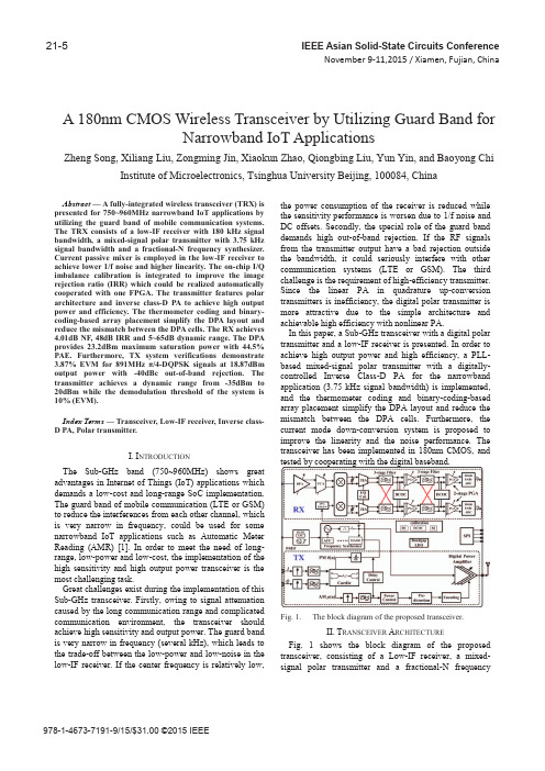
21-5IEEE Asian Solid-State Circuits ConferenceNovember 9-11,2015 / Xiamen, Fujian, China978-1-4673-7191-9/15/$31.00 ©2015 IEEEA 180nm CMOS Wireless Transceiver by Utilizing Guard Band forNarrowband IoT ApplicationsZheng Song, Xiliang Liu, Zongming Jin, Xiaokun Zhao, Qiongbing Liu, Yun Yin, and Baoyong ChiInstitute of Microelectronics, Tsinghua University Beijing, 100084, ChinaAbstract — A fully-integrated wireless transceiver (TRX) is presented for 750~960MHz narrowband IoT applications by utilizing the guard band of mobile communication systems. The TRX consists of a low-IF receiver with 180 kHz signal bandwidth, a mixed-signal polar transmitter with 3.75 kHz signal bandwidth and a fractional-N frequency synthesizer. Current passive mixer is employed in the low-IF receiver to achieve lower 1/f noise and higher linearity. The on-chip I/Q imbalance calibration is integrated to improve the image rejection ratio (IRR) which could be realized automatically cooperated with one FPGA. The transmitter features polar architecture and inverse class-D PA to achieve high output power and efficiency. The thermometer coding and binary-coding-based array placement simplify the DPA layout and reduce the mismatch between the DPA cells. The RX achieves 4.01dB NF, 48dB IRR and 5~65dB dynamic range. The DPA provides 23.2dBm maximum saturation power with 44.5% PAE. Furthermore, TX system verifications demonstrate 3.87% EVM for 891MHz π/4-DQPSK signals at 18.87dBm output power with -40dBc out-of-band rejection. The transmitter achieves a dynamic range from -35dBm to 20dBm while the demodulation threshold of the system is 10% (EVM).Index Terms — Transceiver, Low-IF receiver, Inverse class-D PA, Polar transmitter.I. I NTRODUCTIONThe Sub-GHz band (750~960MHz) shows great advantages in Internet of Things (IoT) applications which demands a low-cost and long-range SoC implementation. The guard band of mobile communication (LTE or GSM) to reduce the interferences from each other channel, which is very narrow in frequency, could be used for some narrowband IoT applications such as Automatic Meter Reading (AMR) [1]. In order to meet the need of long-range, low-power and low-cost, the implementation of the high sensitivity and high output power transceiver is the most challenging task.Great challenges exist during the implementation of this Sub-GHz transceiver. Firstly, owing to signal attenuation caused by the long communication range and complicatedcommunication environment, the transceiver shouldachieve high sensitivity and output power. The guard bandis very narrow in frequency (several kHz), which leads to the trade-off between the low-power and low-noise in the low-IF receiver. If the center frequency is relatively low, the power consumption of the receiver is reduced while the sensitivity performance is worsen due to 1/f noise and DC offsets. Secondly, the special role of the guard band demands high out-of-band rejection. If the RF signals from the transmitter output have a bad rejection outside the bandwidth, it could seriously interfere with other communication systems (LTE or GSM). The third challenge is the requirement of high-efficiency transmitter. Since the linear PA in quadrature up-conversion transmitters is inefficiency, the digital polar transmitter is more attractive due to the simple architecture and achievable high efficiency with nonlinear PA.In this paper, a Sub-GHz transceiver with a digital polar transmitter and a low-IF receiver is presented. In order to achieve high output power and high efficiency, a PLL-based mixed-signal polar transmitter with a digitally-controlled Inverse Class-D PA for the narrowband application (3.75 kHz signal bandwidth) is implemented, and the thermometer coding and binary-coding-based array placement simplify the DPA layout and reduce the mismatch between the DPA cells. Furthermore, the current mode down-conversion system is proposed to improve the linearity and the noise performance. The transceiver has been implemented in 180nm CMOS, and tested by cooperating with the digital baseband.Fig. 1. The block diagram of the proposed transceiver.II. T RANSCEIVER A RCHITECTURE Fig. 1 shows the block diagram of the proposed transceiver, consisting of a Low-IF receiver, a mixed-signal polar transmitter and a fractional-N frequencysynthesizer. Besides, the bandgap-based bias circuit, low-dropout regulators (LDOs), digitally controlled crystal oscillator (DCXO) and SPI interface have been integrated on chip to achieve higher integration.Due to the rigorous demand on the noise, the inductively degenerated common-source balun-LNA is used to interface with the antenna and implement the single-ended-to-differential conversion. Since the IF center frequency after the down-conversion is located nearby the zero frequency, a current passive mixer is utilized due to its lower 1/f noise and higher linearity. After the down-conversion, the IF current signal is injected into the TIA which could convert the signal from the current to the voltage domain. The analog baseband consists of an I/Q imbalance calibration circuit, two 3rd-order complex band-pass filters (C-BPFs) with one embedded programmable-gain amplifier (PGA) stage to reduce the noise, another two PGA stages (the PGAs provide 5-65dB gain dynamic range totally) and a 10 bit SAR ADC. With the aid of one FPGA, the digitally-assisted I/Q imbalance self-calibration loop is also realized. Besides, DC offset cancellation (DCOC), automatic frequency controlling (AFC) and the filter frequency tuning circuit are also included. The signal bandwidth of the receiver front-end is 180 kHz and the following digital baseband would extract the useful narrowband signals through the digital filtering.In the TX, the baseband I/Q signals with 60 kHz sampling rate are fed to the chip through JESD-207 interface and then up-sampled to 480 kHz. After that I/Q signals are converted into separate amplitude and phase signals with the Cordic algorithm. In the amplitude path, the signal is further up-sampled to 2.4MHz for a better image rejection. An adaptive digital pre-distortion (DPD) is used to ensure the high linearity of the DPA, and a binary-to-thermometer encoder is adopted to generate the amplitude control word (ACW) and achieve the high matching among the DPA cells. In the phase path, the signal is converted to a frequency signal with the difference operation. Due to the phase periodicity, the frequency signal can be added or subtracted by 2π to limit the maximum allowable frequency pulse, and then injected into the multi-stage noise shaping MASH modulator. The fractional-N frequency synthesizer realizes the closed loop phase modulation and the phase signal is restored by the integral operation of the VCO. The amplitude ACW and the phase-modulated RF signal, which carry the amplitude and phase signal, respectively, are combined by AND gates to implement the multiplier operation, and then transmitted by the DPA. The signal bandwidth supported by the transmitter is only 3.75 kHz.Fig. 2. The schematic of the DPA cell.III.I MPLEMENTATION OF T HE DPA Generally, the PAs have to trade-off between efficiency and linearity. To cooperate with the non-constant envelope modulation scheme, linear PAs are often used to avoid the distortion in the quadrature up-conversion transmitters, but efficiency is lowered down at the same time. However, in the polar architecture, a switched-mode PA topology can be utilized to achieve high efficiency and the extensive usage of the digital pre-distortion could improve the linearity. Compared to the Class-D PA which has low efficiency due to the transistor drain parasitic capacitance in GHz-range applications, the inverse Class-D PA has drawn more attraction due to its simplified passive network and improved efficiency [2]. In an inverse class-D PA, there is ideally no overlap between the sinusoidal voltage and square current waveforms, thereby achieving 100% efficiency in principle. Moreover, the charge-discharge problem due to the transistor drain parasitic capacitance can be solved in the inverse class-D PA, due to the zero voltage across the switching transistor when it turns on. A parallel LC resonator provides a short circuit for higher order harmonics and reduces the efficiency loss. The DPA cell consisting of one cascode inverse class-D PA and an AND gate is shown in Fig. 2. The switching transistors are driven by the rail-to-rail output signals of the AND gate, meanwhile the cascode transistors, which protects the switching transistors from the large voltage swing at the output, are connected to a reconfigurable bias from the bandgap.This DPA will actually be used as an RF-DAC in the polar transmitter, where the DPA cells are switched in or out according to the ACW (Fig. 3). Since the DPA nonlinearity degrades the effective number of bits (ENOBs), 10 integer and 2 fractional bits are required for binary ACW to cover 63dB dynamic range.Fig. 3.Block diagram of the DPA array.To simplify the layout and reduce the mismatch between the DPA cells, the thermometer coding and binary-coding-based array placement have been adopted in the DPA implementation. The integral parts of the ACW are thermometer-coded, in which the highest 6-bits generate the control-word for 63 DPA 16x-cells (its size is 16 times the size of 1x-cell), while the lowest 4-bits are responsible for 15 DPA 1x-cells. The fractional parts of the ACW directly controls the DPA 0.5x and 0.25x-cells, and all the other 16-bits are then converted into 1-bit high-speed control-word to achieve a smaller precision through the sigma-delta modulator. Since all the DPA cells are connected together in the drain, the ACW can directly control the amplitude of the DPA output and the combination of the ACW and phase-modulated RF signal is realized finally.With the mixed coding, the layout is simplified greatly while good matching is still maintained. After the digital pre-distortion, the DPA achieves 23.2dBm maximum output power with 50.1% drain efficiency.LNATCAMIXERTIA IQ.Cal3-stage C-BPF2-stage PGA 10-bit ADCLDODCXOSPIFrequency SynthesizerLDOBandgapDPATX Digital3-stage C-BPF PGAFig. 4. Microphotography of the proposed transceiver.IV. M EASURED R ESULTSThe proposed Sub-GHz transceiver has been implemented in 180nm CMOS, and consumes a die area of 3.5 x 5mm2 including ESD I/O and pads (Fig. 4). All the I/Os are bondwired to the PCB board for the test purpose and the whole TRX is also tested by cooperating with the digital baseband. A. Frequency SynthesizerThe VCO can be reconfigurable to work in class-A mode or class-C mode, and the tuning range covers from 1.43GHz to 1.92GHz. As shown in Fig. 5, the closed-loop phase noise from 1.728GHz carrier is -120.06dBc/Hz at 1 MHz offset. Since the LO frequency is only half of the testing point, the actual phase noise would be 6dB better.Fig. 5. Measured phase noise of the frequency synthesizer (fc=1.728GHz).B. Cascaded NFSince the IF signal is located nearby the zero frequency, the RX cascaded NF performance cannot be measured by the noise analyzer. The cascaded NF is tested by injecting a test tone into the input of the RX, and then performing the FFT analysis for the ADC outputs. Fig 6 shows the measured results of the FFT analysis, which indicates the equivalent cascaded NF =Pin-Nin-SNRout=4.05dB.Fig. 6. Measured FFT spectrum of the RX chain fromC. DPAThe output power of the DPA is controlled by the amplitude control word, the pre-distortion is employed to improve the linearity performance of the DPA due to the serious AM-AM distortion at high output power. As shown in Fig. 7, the PA output power is measured by sweeping the ACW after digital pre-distortion. Under 2V power supply, the PA achieves a peak output power of 23.2dBm, with 50.1% drain efficiency and 44.5% PAE (including the power consumption of the drivers).Fig. 7. Measured PA output power and PAE at 891MHz for different amplitude code-words.*the insertion loss of the SMA cable and balun includedFig. 8. Measured output spectrum, constellation and EVM for 891MHz π/4-DQPSK signals (the output power is 18.87dBm)Fig. 9. TX EVM versus Output PowerD.Transmitter System VerificationThe system performance of the transmitter is tested with 3.75 kHz π/4-DQPSK signals. As shown in Fig. 8, the output signal (891MHz) can be demodulated the measured EVM is 3.87% while transmitting an average power of 18.87dBm with 33.4% average PAE. The transmitted out-of-band output signal is below -40dBc outside 9 kHz offset from the carrier center and have a negligible effect on other communication systems (LTE or GSM).In order to test the transmitter dynamic range, the EVM versus the PA output power is measured. As shown in Fig. 9, the EVM degradation occurs at high or low output power levels. As the output power is increased to the gain compression region of the DPA, the distortion occurs and thus the EVM of the whole system is declined. Besides, our signal bandwidth is only 3.75 kHz and the LO phase noise from 1 kHz to 10 kHz also affects the modulation accuracy and contributes to EVM. As the output power is dropped below -30dBm, the EVM deteriorates sharply from 2% to 5%. Since the demodulation threshold of the system is 10%, our transmitter achieves a dynamic range from -35dBm to 20dBm.TABLE I summarizes the performance of the presented Sub-GHz TRX and make a comparison with the state-of-art. It could be seen our receiver optimizes the DC power while achieving the comparable or better performance in other key specifications. Besides, our transmitter achieves the highest output power and PAE.TABLE IP ERFORMANCE S UMMARY AND C OMPARISON Index This work [2] [3] [4] Technology 180nm 65nm 90nm 180nm Freq(GHz) 0.75~0.96 2.4 2.40.36~0.542.36~2.5BW(MHz)0.18/0.0037520 2 0.15-3RX NF(dB) 4.05 - - 3.9/4.4 IRR(dBc) 48 - - 26Pout(dBm) 23.2 21.8 20 4.7/3.1PAE(%) 44.5 44 38.5 ~EVM(%)3.87@18.87dBm3.98 1.8 ~Out-of-bandrejection(dBc)-40@9 k18.87dBm-40@20M14dBm-55@2.5M14dBm-20@150 k1.6dBm Power(mW) RX: 25RX:15.8/16.6VII.C ONCLUSIONSIn this work, A Sub-GHz transceiver for narrowband IoT application has been implemented in 180nm CMOS. The receiver achieves 4.05dB NF, 48dB IRR and only consumes 25mW from one 1.7V power supply. A mixed-signal polar transmitter with a high-efficiency integrated inverse class-D PA is presented. The PA achieves 23.2dBm maximum power with 44.5% PAE. The measured EVM is 3.87% with 33.4% average PAE at 18.87dBm output power for π/4-DQPSK modulation signals and the out-of-band rejection is below -40dBc.R EFERENCES[1] 3GPP TS 36.101: User Equipment (UE) RadioTransmission and Reception (Release 12). March 2015. [2] D. Chowdhury, et al. “A Fully-Integrated Efficient CMOSInverse Class-D Power Amplifier for Digital Polar Transmitters,” IEEE J. of Solid-State Circuits., vol. 47, no.5, pp. 1113-1122, May 2012.[3] Stauth, Jason T., and Seth R. Sanders. “A 2.4 GHz, 20dBmclass-D PA with single-bit digital polar modulation in 90nmCMOS,” Custom Integrated Circuits Conference, IEEE CICC, pp. 737-740, 2008.[4] Lingwei Zhang et al., “A Reconfigurable Sliding-IF Transc-eiver for 400 MHz/2.4 GHz IEEE 802.15.6/ZigBee WBANHubs with Only 21% Tuning Range VCO,” IEEE J. of Solid-State Circuits., vol. 48, no. 11, pp. 2705-2716, Nov2013.。
UTC4052
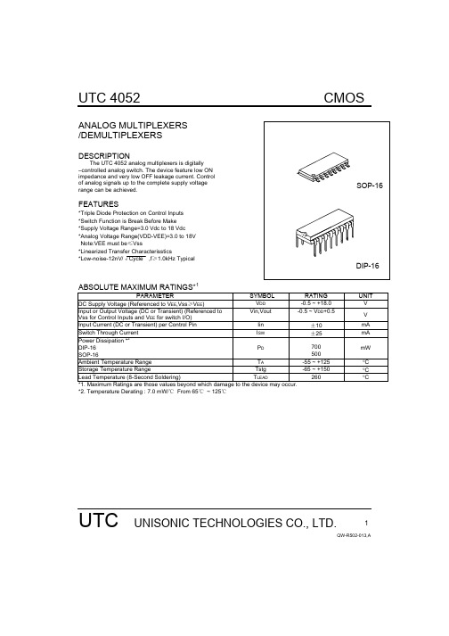
VIL Ron=per spec,
Voltage
Ioff=per spec
VDD=5.0V
1.5
2.25 1.5
1.5 V
VDD=10V
3.0
4.50 3.0
3.0
VDD=15V
4.0
6.75 4.0
4.0
High-Level Input
VIH Ron=per spec,
Voltage
Ioff=per spec
10
0.010 10
300
20
0.015 20
600
Total Supply Current ID(AV) TA=25℃only (The
(Dynamic Plus
channel component,
Quiescent, Per
(Vin-Vout) /Ron, is not
Package
included.)
Propagation Delay Times(Figure 4) Control Input to Output
Second Harmonic Distortion
tPLH,tPHL
tPHZ,tPLZ tPZH,tPZL
tPLN,tPHL
RL=10kΩ
VDD-VEE= 5.0, tPLH,tPHL=(0.17 ns/pF) CL+21.5 ns VDD-VEE=10, tPLH,tPHL=(0.08 ns/pF) CL+8.0 ns VDD-VEE=15, tPLH,tPHL=(0.06 ns/pF) CL+7.0 ns RL=10kΩ,VEE=Vss Output”1” or “0” to High Impedance, or High Impedance to”1” or “0” Level VDD-VEE= 5.0 VDD-VEE=10 VDD-VEE=15 RL=10kΩ,VEE=Vss VDD-VEE= 5.0 VDD-VEE=10 VDD-VEE=15 RL=10kΩ, f=1kHz, Vin=5Vpp, VDD-VEE=10
(完整word版)光纤通信RF方面的中英文翻译

(完整word版)光纤通信RF方面的中英文翻译RF和微波光纤设计指引Name:Class:Student NO.:(完整word版)光纤通信RF方面的中英文翻译RF and Microwave Fiber-Optic Design GuideAgere Systems Inc., through its predecessors, began developing and producing lasers and detectors for linear fiber-optic links nearly two decades ago. Over time, these optoelectronic components have been continually refined for integration into a variety of systems that require high fidelity, high frequency, or long-distance transportation of analog and digital signals. As a result of this widespread use and development, by the late 1980s, these link products were routinely being treated as standard RF and microwave components in many different applications.There are several notable advantages of fiber optics that have led to its increasing use. The most immediate benefit of fiber optics is its low loss. With less than 0.4 dB/km of optical attenuation, fiber-optic links send signals tens of kilometers and still maintain nearly the original quality of the input.The low fiber loss is also independent of frequency for most practical systems. With laser and detector speeds up to 18 GHz, links can send high-frequency signals in their original form without the need to downconvert or digitize them for the transmission portion of a system. As a result, signal conversion equipment can be placed in convenient locations or even eliminated altogether, which often leads to significant cost and maintenancesavings.Savings are also realized due to the mechanical flexibility and lightweight fiber-optic cable, approximately 1/25 the weight of waveguide and 1/10 that of coax. Many transmission lines can be fed through small conduits, allowing for high signal rates without investing in expensive architectural supports. The placement of fiber cable is further simplified by the natural immunity of optical fiber to electromagnetic interference (EMI). Not only can large numbers of fibers be tightly bundled with power cables, they also provide a uniquely secure and electrically isolated transmission path.The general advantages of fiber-optics first led to their widespread use in long-haul digital telecommunications. In the most basic form of fiber-optic communications, light from a semiconductor laser or LED is switched on and off to send digitally coded information through a fiber to a photodiode receiver.By comparison, in linear fiber-optic systems developed by Lucent, the light sent through the fiber has an intensity directly related to the input electrical current. While this places extra requirements on the quality of the lasers and photodiodes, it has been essential in many applications to transmit arbitrary RF and microwave signals. As a result, tens of thousands of Agere Systems’ transmitters are currently in use.The information offered here examines the basic link components, provides an overview of design calculations related to gain, bandwidth, noise, and dynamic range and distortion. A section on fiber-optic components discusses a number of key parameters, among them wavelength and loss, dispersion, reflections, and polarization and attenuation. Additional information evaluates optical isolators, distributed-feedback lasers and Fabry-Perot lasers, predistortion, and short- vs. long-wavelength transmission.One of linear optical fiber relation main usages or receives between the electronicinstallation and the remote localization antenna in the transmission transmits RF and the microwave signal。
联邦快递公司发展分析

联邦快递公司发展分析 Document serial number【KKGB-LBS98YT-BS8CB-BSUT-BST108】联邦快递公司发展分析FedEx为快递运输公司,服务范围涵盖全球220多个国家与地区,出入全球375座机场,能于1至2天内提供直接到府递送服务,并且有保证准时、否则退费之承诺。
全球总部设于美国田纳西州曼斐斯(Memphis, Tennessee),而加拿大、欧洲、亚洲、拉丁美洲等地区总部分别位于安大略多伦多(Toronto, Ontario)、比利时布鲁塞尔(Brussels, Belgium)、香港(Hong Kong)、佛罗里达州迈阿密(Miami, Florida)。
全球有10座航空快递转运中心、894个快递营运点;29座陆上货运转运中心、超过500座货运站;324个货运营运中心;1,500处Kinko’s营运中心。
4.1 发展背景与历程FedEx系Frederick W. Smith在1971年成立于美国阿肯色州小岩城(Little Rock, Arkansas)。
1977年政府放宽限制,FedEx购置7架比原有机型容量大七倍的Boeing 727飞机,大幅提升运载能力。
1981年,FedEx扩展版图至加拿大,开启国际递送服务首航。
FedEx于1989年藉由并购飞虎公司(Flying Tigers)扩展在国际地位,并顺利获得亚洲21个国家的航权。
1995年FedEx启用FedEx AsiaOne网络,并于菲律宾苏比克湾(Subic Bay, Philippine)设置首座亚太地区转运中心,提供全亚洲各地隔夜送达服务(overnight service),并且运用在美国营运所实行的创新「轮轴与轮幅式」运输概念。
1999年启用FedEx EuroOne网络,于巴黎戴高乐国际机场(Roisy-Charles de Gaulle airport)设置转运中心。
以下则列出FedEx分别在版图扩展以及并购与结盟重要历程[][][][][][][][][][][][][][][],FedEx相关基本资料如。
基于负反馈技术的嵌套式直流失调消除电路
微电子技术基于负反馈技术的嵌套式直流失调消除电路鄢张芳玲打雷倩倩打张旭东打李弦2,李连碧1(1.西安工程大学理学院,陕西西安710000;2.深圳市纽瑞芯科技有限公司,广东深圳518000)摘要:基于UMC40nm CMOS工艺,设计了一种带有直流失调消除电路(DCOC)的可编程增益放大器(PGA),该PGA采用闭环电阻反馈结构,由两级增益单元级联构成。
DCOC电路基于传统的直流负反馈结构,针对多级级联的方式,提出了一种嵌套式反馈方法,可降低电路功耗和面积。
仿真结果表明,DCOC在0-52dB的增益变化范围内高通截止频率恒为10kHz,相对抑制度恒为50dB,且在0dB时可矫正的最大输入失调量为110mV。
与传统设计方法相比,DCOC的面积减小近一半。
关键词:直流失调消除;嵌套式反馈;可编程增益放大器中图分类号:TN722文献标识码:A DOI:10.16157/j.issn.0258-7998.201136中文引用格式:张芳玲,雷倩倩,张旭东,等.基于负反馈技术的嵌套式直流失调消除电路[J].电子技术应用袁2021,47 (5):50-5358.英文弓I用格式:Zhang Fangling,Lei Qianqian,Zhang Xudong,et al.A nested DC offset cancellation circuit based on negative feedback technique[J].Application of Electronic Technique,2021,47(5):50-53,58.A nested DC offset cancellation circuit based on negative feedback techniqueZhang Fangling1,Lei Qianqian1,Zhang Xudong1,Li Xian2,LI Lianbi1(1.School of Science,Xi'an Polytechnic University,Xi'an710000,China;2.Shenzhen Niureixin Technology Co.,Ltd.,Shenzhen518000,China)Abstract:Based on the UMC40nm CMOS process,a programmable gain amplifier(PGA)with DC offset cancellation circuit(DCOC) is designed.The PGA adopts a closed-loop resistance negative feedback structure and consists of a cascade of two gain units. DCOC circuit is based on the traditional DC negative feedback structure,a nested feedback method is proposed to reduce the power consumption and area of DCOC circuit.The simulation results show that within the gain variation control range of0~52dB,the high pass cutoff frequency and the relative inhibition degree of DCOC are constant at10kHz and50dB,and the maximum correctable input misalignment at0dB pared with the traditional design method,the area of DCOC has been reduced by almost half.Key words:DC offset cancellation;nested feedback;programmable gain amplifier0引言随着可编程增益放大器(Programmable Gain Amplifier, PGA)放大倍数的增大,尤其在给接收链路提供较大增益时[1-3],直流失调的问题就越来越严重,使得下一级电路处于饱和状态。
- 1、下载文档前请自行甄别文档内容的完整性,平台不提供额外的编辑、内容补充、找答案等附加服务。
- 2、"仅部分预览"的文档,不可在线预览部分如存在完整性等问题,可反馈申请退款(可完整预览的文档不适用该条件!)。
- 3、如文档侵犯您的权益,请联系客服反馈,我们会尽快为您处理(人工客服工作时间:9:00-18:30)。
---------------------------------------------------------------最新资料推荐------------------------------------------------------
Digitally-Assisted Analog and RF CMOS
Circuit Design for Software-Defined Radio
Digitally-Assisted Analog and RF CMOS CircuitDesign for Software-Def i ned RadioKenichi Okada Shouhei KousaiEditorsDigitally-Assisted Analogand RF CMOS CircuitDesign for Software-Def i nedRadio123EditorsKenichi OkadaDepartment of Physical ElectronicsGraduate School of Science and EngineeringTokyo Institute of TechnologyTokyo, Japanokada@ssc.pe.titech.ac.jpShouhei KousaiAdvanced Circuit Design DepartmentCenter for Semiconductor Researchand Development Toshiba CorporationKawasaki, Japanshouhei.kousai@toshiba.co.jpISBN 978-1-4419-8513-2 e-ISBN 978-1-4419-8514-9DOI 10.1007/978-1-4419-8514-9Springer New York Dordrecht Heidelberg LondonLibrary of Congress Control Number: 2019935146 Springer Science+Business Media, LLC 2019All rights reserved. This work may not be translated or copied in whole or in part without the writtenpermission of the publisher (Springer Science+Business Media, LLC, 233 Spring Street, New York,NY 10013, USA), except for brief excerpts in connection with reviews or scholarly analysis. Use inconnection with any
1 / 2
form of information storage and retrieval, electronic adaptation, computer software,or by similar or dissimilar methodology now known or hereafter developed is forbidden.The use in this publication of trade names, trademarks, service marks, and similar terms, even if they arenot identif i ed as such, is not to be taken as an expression of opinion as to whether or not they are subjectto proprietary rights.Printed on acid-free paperSpringer is part of Springer Science+Business Media ()PrefaceSoftware-def i ned radios (SDRs) that are capable of transmitting and receivingmodulated signals in any frequency band have long been desired. They are veryattractive, especially as mobile devices, since mobile devices need to be compacteven if they are compliant with many different wireless standards. In fact, recentmobile devices are required to offer an enormous range of wireless standards (e.g.,2G/3G/3.5G/3.9G/4G cellular, WLAN/WPAN, GPS, broadcasting).For many years, var...。