第六章 simulink模块库介绍
simulink各模块详解-simulink模块

7. “Extra Library”模块库
其中包含Simpower模块库中各类模块的扩充模块
二、 直流电路仿真
【例2_1】 测量下图所示电路的节点电压。
见Sim6_2_1.mdl
说 明
1. 模块库中没有直流电流源模块,可对“AC Current Source”模块进行适当设置:
2. 模块库中没有单独的电阻模块,可对 “Series RLC Branch”模块进行适当设置:
【例2_2】 测量下图所示电路的电流I。
见Sim6_2_2.mdl
说 明
CCCS的仿真模型
设置电流增益
取得控制电流Ix
受控电流源 注意参考方向
2. “Electrical Sources”模块库
其中包括7个用于产生电源信号的模块 功能说明 可编辑三相电源 三相电源
交流电流源
交流电压 受控电流源 受控电压源
直流电压源
3. “Elements”模块库
其中包括的是线性及非线性的电路网络元件模块,可分为 Elements(元件类)、Lines(导线类)、Circuit Breaker(开关类)、 Transformer(变压器类)共四类24个模块
功能说明
三相动力负载 三相互感线圈
三相并联RLC支路 三相并联RLC负载 三相串联RLC支路 三相串联RLC负载 三相开关 三相短路电路 三相电力传输线 三相变压器
功能说明
一般电路开关 多相分布电力传输线 线性变压器 互感线圈 并联RLC支路 并联RLC负载 单相电力传输线 饱和变压器 串联RLC支路 串联RLC负载 电涌放电器 三相变压器(三绕组) 三相变压器(两绕组) Y形变换三相变压器
6.2 Simulink电路分析应用
simulink模块库介绍
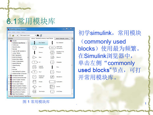
图 18
x F
.
26
解法1: 构建常微分方程
根据牛顿运动定律,得到小车的运动方程 kx fx mx F 将相关参数代入上式得 x 4 x 3x F 将上述微分方程改写为
x u(t ) 4 x 3x
.
6
图7
.
7
图8
3、数据类型转换模块
Data type conversion 可将输入数据类型转换为 指定输出类型。具体选择有:inherit(与输入数据保 持一致)、double、single、int8等。同时可以选择取 整方向。Zero:向零取整;nearest:向最接近整数取 整;floor:向负无穷取整;ceiling:向正无穷取整。
.
8
4、积分模块
Integrator模块为连续时间积分单元。双击图9中 该模块,在initial condition可设置积分其初始值,在 limit output可设置输出最大和最小值。仿真运行结果 如图10所示。
.
9
图9
图 10
. 10
5、离散时间积分模块
Discrete time integrator(离散时间积分),可完 成离散系统积分作用。如图11所示,双击离散积分模 块,设置gainvalue(积分增益值),改变积分速度。 在sample time文本框可设置离散积分采样时间,如设 置为-1,表示与输入信号采样时间一致。在limit output可设置积分输出上下限。在图11中设置 Discrete time integrator1模块增益值为2,采样时间为 0.5,仿真结果如图12所示。
6.1常用模块库
初学simulink,常用模块 (commonly used blocks)使用最为频繁。 在Simulink浏览器中, 单击左侧“commonly used blocks”节点,可打 开常用模块库。
SIMULINK模块介绍
SIMULINK模块介绍simulink模块介绍Simulink是一种基于模块化的工具,用于建立和仿真动态系统。
它是MATLAB的一个扩展模块,主要用于进行连续时间和离散时间系统的建模、仿真和分析。
Simulink的模块化设计使得用户可以通过简单地将各种模块连接在一起来构建复杂的系统模型。
Simulink提供了一个可视化的环境,让用户可以通过图形化方式来建立系统模型。
用户可以通过拖放不同的模块,如输入、输出、运算符等,来创建系统模型。
用户还可以通过调整模块的参数来定义系统的行为。
Simulink的模块库包含了各种各样的模块,用于建立各种类型的系统模型。
例如,Simulink提供了模块用于建立传感器和执行器的模型,模块用于建立控制器的模型,以及模块用于建立动力系统的模型等。
用户可以根据自己的需要选择合适的模块来创建系统模型。
Simulink还提供了丰富的仿真功能,使用户可以对系统模型进行仿真和分析。
用户可以设置模拟的时间范围、步长和求解器等参数,来执行仿真。
Simulink会根据用户设置的参数来计算系统模型在仿真时间范围内的行为,并将结果显示在仿真结果图中。
用户还可以在仿真过程中观察系统的动态行为,并进行数据分析。
Simulink还支持代码生成功能,可以将用户创建的系统模型转换为可执行的代码。
用户可以选择不同的目标平台,如嵌入式系统、实时系统等,来生成相应的代码。
生成的代码可以直接用于控制硬件设备,例如实现自动驾驶等应用。
除了基本的建模和仿真功能外,Simulink还提供了许多高级功能,用于更复杂的系统分析和设计。
例如,Simulink提供了参数优化功能,用户可以根据给定的性能指标来优化系统模型的参数。
Simulink还提供了系统辨识功能,可以从实际系统的输入输出数据中,估计出系统的动态模型。
Simulink还可以与其他工具进行集成,如MATLAB、Stateflow等,进一步扩展系统建模和仿真的功能。
Simulink常用库模块介绍

Simulink常用库模块介绍1. Sources Library(源库):该库提供了一些用于输入信号的模块,如步进信号、正弦信号、随机信号等。
用户可以根据自己的需求选择适合的信号类型。
2. Sinks Library(输出库):该库提供了一些用于输出和记录信号的模块,如作用在信号上的示波器、记录信号的Scope等。
3. Continuous Library(连续库):该库提供了一些用于连续时间系统的模块,如积分器、微分器、比例积分微分控制器(PID)等。
这些模块可以用于建立和仿真连续时间动态系统。
4. Discrete Library(离散库):该库提供了一些用于离散时间系统的模块,如采样器、保持器、差分器等。
这些模块可以用于建立和仿真离散时间动态系统。
5. Logic and Bit Operations Library(逻辑和位运算库):该库提供了一些用于逻辑运算和位运算的模块,如AND门、OR门、XOR门、移位器等。
这些模块可以用于建立和仿真逻辑和位运算系统。
6. Math Operations Library(数学运算库):该库提供了一些用于数学运算的模块,如加法器、减法器、乘法器、除法器等。
这些模块可以用于建立和仿真数学运算系统。
7. Lookup Tables Library(查找表库):该库提供了一些用于查找表操作的模块,如一维和多维插值查找表、查找表与插值、查找表与线性插值等。
这些模块可以用于建立和仿真查找表系统。
8. Control Systems Library(控制系统库):该库提供了一些用于控制系统的模块,如PID控制器、状态空间模型、传递函数等。
这些模块可以用于建立和仿真控制系统。
9. Signal Routing Library(信号路由库):该库提供了一些用于信号路由的模块,如切换器、多路复用器、分支器等。
这些模块可以用于控制信号的路由和选择。
10. Simulink Extras Library(额外功能库):该库提供了一些Simulink中的辅助模块,如信号生成器、信号调整器、时间尺度转换器等。
SIMULINK模块库详细介绍

Simulink 模块库——Source
From File(从文件读数据)
模块功能 从文件读数据 模块说明 From File模块从指定的文件读取数据作为其 输出。模块的图标中显示了提供数据的文件 名。文件名必须包含一个两行或两行以上的 矩阵,第一行应是单调递增的时间点,其它 行是与之对应的数据点。 模块数据类型 双精度类型实数信号 模块参数对话框 File name:输入数据的文件名。 Sample time:从文件中读去数据的采样率
Simulink 模块库——Source
Repeating Sequence (重复序列)
模块功能 产生重复的任意信号 模块说明 Repeating Sequence模块可生 成随时间变化的重复信号。波 形任意指定,当仿真达到Time values 向量中的最大时间值时, 信号开始重复。 模块数据类型 双精度类型实数信号 模块参数对话框 Time values:单调增加的时 间向量(s) Output values:与Time values对应的输出向量
操作 单击 SIMULINK 图标 操作 或 键入 SIMULINK
1结果 打开 Library 模块库窗口
操作 双击“新建”图标 1结果 打开 simulink 工作窗,
默认名 untitled
SIMULINK 图库中 含连续部分的图元
模块库有关项目
点击模块库前面的“+”号 图标展开列出库中图元
Simulink 模块库——Source
Sine Wave(正弦波)
模块功能 产生一个正弦波 模块说明 Sine Wave 提供连续或离散形式的正弦波。 模块数据类型 双精度类型实数信号 模块参数对话框 Amplitude:信号的幅度 Frequency:信号的频率( rad/sec ) Phase:信号的相位(rad) Sample time:采样周期(0:连续;>0: 离散采样时间;-1:工作模式与接受信号 模式相同) y= Amplitude×sin(Frequency ×time+Phase)
SIMULINK的模块库介绍

SIMULINK的模块库介绍(1)Commonly UsedBus Creator Create signal busBus Selector Select signals from incoming busConstant Generate constant valueData Type Conversion Convert input signal to specified data typeDemux Extract and output elements of vector signalDiscrete-TimeIntegratorPerform discrete-time integration or accumulation of signal Gain Multiply input by constantGround Ground unconnected input portInport Create input port for subsystem or external input Integrator,IntegratorLimitedIntegrate signalLogical Operator Perform specified logical operation on inputMux Combine several input signals into vectorOutport Create output port for subsystem or external outputProduct Multiply and divide scalars and nonscalars or multiply and invert matricesRelational Operator Perform specified relational operation on inputs Saturation Limit range of signalScope and Floating Display signals generated during simulationScopeSubsystem,AtomicSubsystem,NonvirtualSubsystem,CodeReuseSubsystemRepresent system within another systemSum,Add,Subtract,Sum of ElementsAdd or subtract inputsSwitch Switch output between first input and third input based on value of second inputTerminator Terminate unconnected output portUnit Delay Delay signal one sample period(2)ContinuousDerivative Output time derivative of inputIntegrator,IntegratorLimitedIntegrate signalPID Controller Simulate continuous-or discrete-time PID controllersPID Controller(2 DOF) Simulate continuous-or discrete-time two-degree-of-freedom PID controllersSecond-OrderIntegrator,Second-Order Integrator LimitedIntegrate input signal twiceState-Space Implement linear state-space system Transfer Fcn Model linear system by transfer function Transport Delay Delay input by given amount of time Variable TimeDelay,VariableTransport DelayDelay input by variable amount of timeZero-Pole Model system by zero-pole-gain transfer function (3)DiscontinuitiesBacklash Model behavior of system with playCoulomb and ViscousModel discontinuity at zero,with linear gain elsewhere FrictionDead Zone Provide region of zero outputDead Zone Dynamic Set inputs within bounds to zeroHit Crossing Detect crossing pointQuantizer Discretize input at specified intervalRate Limiter Limit rate of change of signalRate Limiter Dynamic Limit rising and falling rates of signalRelay Switch output between two constantsSaturation Limit range of signalSaturation Dynamic Bound range of inputWrap To Zero Set output to zero if input is above threshold(4)DiscreteDifference Calculate change in signal over one time stepDiscrete Derivative Compute discrete time derivativeDiscrete Filter Model Infinite Impulse Response(IIR)direct form II filtersDiscrete FIR Filter Model FIR filtersDiscrete State-Space Implement discrete state-space systemDiscrete Transfer Fcn Implement discrete transfer functionDiscrete Zero-Pole Model system defined by zeros and poles of discrete transfer function Discrete-TimeIntegratorPerform discrete-time integration or accumulation of signalFirst-Order Hold Implement first-order sample-and-holdInteger Delay Delay signal N sample periodsMemory Output input from previous time stepPID Controller Simulate continuous-or discrete-time PID controllersPID Controller(2 DOF) Simulate continuous-or discrete-time two-degree-of-freedom PID controllersTapped Delay Delay scalar signal multiple sample periods and output all delayed versionsTransfer Fcn FirstOrderImplement discrete-time first order transfer functionTransfer Fcn Lead orLagImplement discrete-time lead or lag compensatorTransfer Fcn RealZeroImplement discrete-time transfer function that has real zero and no pole Unit Delay Delay signal one sample periodZero-Order Hold Implement zero-order hold of one sample period(5)Logic and BitOperationsBit Clear Set specified bit of stored integer to zeroBit Set Set specified bit of stored integer to oneBitwise Operator Specified bitwise operation on inputs Combinatorial Logic Implement truth tableCompare To Constant Determine how signal compares to specified constant Compare To Zero Determine how signal compares to zeroDetect Change Detect change in signal valueDetect Decrease Detect decrease in signal valueDetect Fall Negative Detect falling edge when signal value decreases to strictly negative value,and its previous value was nonnegativeDetect Fall Nonpositive Detect falling edge when signal value decreases to nonpositive value,and its previous value was strictly positiveDetect Increase Detect increase in signal valueDetect Rise Nonnegative Detect rising edge when signal value increases to nonnegative value,and its previous value was strictly negativeDetect Rise Positive Detect rising edge when signal value increases to strictly positive value,and its previous value was nonpositiveExtract Bits Output selection of contiguous bits from input signal Interval Test Determine if signal is in specified intervalInterval Test Dynamic Determine if signal is in specified intervalLogical Operator Perform specified logical operation on input Relational Operator Perform specified relational operation on inputs Shift Arithmetic Shift bits or binary point of signal(6)Lookup TablesDirect LookupTable(n-D)Index into N-dimensional table to retrieve element,column,or 2-D matrixInterpolation Using Prelookup Use precalculated index and fraction values to accelerate approximation of N-dimensional functionLookup Table Approximate one-dimensional functionLookup Table(2-D) Approximate two-dimensional functionLookup Table(n-D) Approximate N-dimensional functionLookup TableDynamicApproximate one-dimensional function using dynamic table Prelookup Compute index and fraction for Interpolation Using Prelookup blockSine,Cosine Implement fixed-point sine or cosine wave using lookup table approach that exploits quarter wave symmetry(7)Math OperationsAbs Output absolute value of inputAlgebraic Constraint Constrain input signal to zeroAssignment Assign values to specified elements of signalBias Add bias to inputComplex toMagnitude-AngleCompute magnitude and/or phase angle of complex signal Complex to Real-Imag Output real and imaginary parts of complex input signalDivide Divide one input by anotherDot Product Generate dot product of two vectorsFind Find nonzero elements in arrayGain Multiply input by constantMagnitude-Angle toComplexConvert magnitude and/or a phase angle signal to complex signal Math Function Perform mathematical functionMatrix Concatenate,Vector Concatenate Concatenate input signals of same data type to create contiguous output signalMinMax Output minimum or maximum input valueMinMax RunningResettableDetermine minimum or maximum of signal over time Permute Dimensions Rearrange dimensions of multidimensional array dimensions Polynomial Perform evaluation of polynomial coefficients on input valuesProduct Multiply and divide scalars and nonscalars or multiply and invert matricesProduct of Elements Copy or invert one scalar input,or collapse one nonscalar input Real-Imag to Complex Convert real and/or imaginary inputs to complex signalReshape Change dimensionality of signalRounding Function Apply rounding function to signalSign Indicate sign of inputSine Wave Function Generate sine wave,using external signal as time sourceSlider Gain Vary scalar gain using sliderSqrt,SignedSqrt,Reciprocal SqrtCalculate square root,signed square root,or reciprocal of square root Squeeze Remove singleton dimensions from multidimensional signal Sum,Add,Subtract,Sum of ElementsAdd or subtract inputsTrigonometricFunctionSpecified trigonometric function on inputUnary Minus Negate inputWeighted SampleTime MathSupport calculations involving sample time(8)Model VerificationAssertion Check whether signal is zeroCheck Discrete Gradient Check that absolute value of difference between successive samples of discrete signal is less than upper boundCheck Dynamic Gap Check that gap of possibly varying width occurs in range of signal's amplitudesCheck DynamicLower BoundCheck that one signal is always less than another signalCheck Dynamic Range Check that signal falls inside range of amplitudes that varies from time step to time stepCheck Dynamic UpperBoundCheck that one signal is always greater than another signal Check InputResolutionCheck that input signal has specified resolutionCheck Static Gap Check that gap exists in signal's range of amplitudesCheck Static Lower Bound Check that signal is greater than(or optionally equal to)static lower boundCheck Static Range Check that signal falls inside fixed range of amplitudesCheck Static UpperBoundCheck that signal is less than(or optionally equal to)static upper bound(9)Model-WideUtilitiesBlock Support Table View data type support for Simulink blocksDocBlock Create text that documents model and save text with modelModel Info Display revision control information in modelTimed-BasedGenerate linear models in base workspace at specific times LinearizationTrigger-BasedGenerate linear models in base workspace when triggered Linearization(10)Ports&SubsystemsTrigger Add trigger port to model or subsystemAction Port Implement Action subsystems used by if and switch control flow statements in Simulink softwareConfigurableSubsystemRepresent any block selected from user-specified library of blocks Enable Add enabling port to subsystemEnabled and Triggered Subsystem Represent subsystem whose execution is enabled and triggered by external inputEnabled Subsystem Represent subsystem whose execution is enabled by external inputFor Each Enable blocks inside For Each Subsystem to process elements or subarrays of input signal independentlyFor Each Subsystem Repeatedly perform algorithm on each element or subarray of input signal and concatenate resultsFor Iterator Repeatedly execute contents of subsystem at current time step until iteration variable exceeds specified iteration limitFor Iterator Subsystem Represent subsystem that executes repeatedly during simulation time stepFunction-Call Generator Execute function-call subsystem specified number of times at specified rateFunction-Call Split Provide junction for splitting function-call signalFunction-CallSubsystemRepresent subsystem that can be invoked as function by another block If Model if-else control flowIf Action Subsystem Represent subsystem whose execution is triggered by If blockInport Create input port for subsystem or external inputModel Include model as block in another modelOutport Create output port for subsystem or external outputSubsystem,AtomicSubsystem,NonvirtualSubsystem,CodeReuseSubsystemRepresent system within another systemSwitch Case Implement C-like switch control flow statementSwitch Case ActionSubsystemRepresent subsystem whose execution is triggered by Switch Case block Triggered Subsystem Represent subsystem whose execution is triggered by external inputWhile Iterator Subsystem Represent subsystem that executes repeatedly while condition is satisfied during simulation time step(11)Signal AttributesSignal Specification Specify desired dimensions,sample time,data type,numeric type,and other attributes of signalBus to Vector Convert virtual bus to vectorData Type Conversion Convert input signal to specified data typeData Type Conversion Inherited Convert from one data type to another using inherited data type and scalingData Type Duplicate Force all inputs to same data typeData Type Propagation Set data type and scaling of propagated signal based on information from reference signalsData Type ScalingStripRemove scaling and map to built in integer IC Set initial value of signalProbe Output signal's attributes,including width,dimensionality,sample time,and/or complex signal flagRate Transition Handle transfer of data between blocks operating at different rates Signal Conversion Convert signal to new type without altering signal values Weighted SampleTimeSupport calculations involving sample timeWidth Output width of input vector(12)Signal RoutingBus Assignment Replace specified bus elementsBus Creator Create signal busBus Selector Select signals from incoming busData Store Memory Define data storeData Store Read Read data from data storeData Store Write Write data to data storeDemux Extract and output elements of vector signalEnvironment Controller Create branches of block diagram that apply only to simulation or only to code generationFrom Accept input from Goto blockGoto Pass block input to From blocksGoto Tag Visibility Define scope of Goto block tagIndex Vector Switch output between different inputs based on value of first input Manual Switch Switch between two inputsMerge Combine multiple signals into single signalMultiport Switch Choose between multiple block inputsMux Combine several input signals into vectorSelector Select input elements from vector,matrix,or multidimensional signalSwitch Switch output between first input and third input based on value of second input(13)SinksDisplay Show value of inputOutport Create output port for subsystem or external output Scope and FloatingDisplay signals generated during simulationScopeStop Simulation Stop simulation when input is nonzeroTerminator Terminate unconnected output portTo File Write data to fileTo Workspace Write data to MATLAB workspaceXY Graph Display X-Y plot of signals using MA TLAB figure window (14)SourcesBand-Limited WhiteNoiseIntroduce white noise into continuous system Chirp Signal Generate sine wave with increasing frequency Clock Display and provide simulation time Constant Generate constant valueCounter Free-Running Count up and overflow back to zero after reaching maximum value for specified number of bitsCounter Limited Count up and wrap back to zero after outputting specified upper limit Digital Clock Output simulation time at specified sampling interval Enumerated Constant Generate enumerated constant valueFrom File Read data from MAT-fileFrom Workspace Read data from workspaceGround Ground unconnected input portInport Create input port for subsystem or external inputPulse Generator Generate square wave pulses at regular intervalsRamp Generate constantly increasing or decreasing signalRandom Number Generate normally distributed random numbersRepeating Sequence Generate arbitrarily shaped periodic signalRepeating Sequence Interpolated Output discrete-time sequence and repeat,interpolating between data pointsRepeating SequenceStairOutput and repeat discrete time sequenceSignal Builder Create and generate interchangeable groups of signals whose waveforms are piecewise linearSignal Generator Generate various waveformsSine Wave Generate sine wave,using simulation time as time source Step Generate step functionUniform RandomNumberGenerate uniformly distributed random numbers(15)User-DefinedFunctionsEmbedded MATLABInclude MATLAB code in models that generate embeddable C code FunctionFcn Apply specified expression to inputLevel-2 M-FileUse Level-2 M-file S-function in modelS-FunctionMATLAB Fcn Apply MATLAB function or expression to inputS-Function Include S-function in modelS-Function Builder Create S-function from C code that you provide(16)AdditionalMath&DiscreteAdditional Discrete Provide additional discrete math supportAdditional Increment or decrement value of signal by oneMath:Increment—Dec rement。
第六章 Simulink
From File参数设置
传递函数(Transfer function) 参数设置
Numerator为分子多项式系数 Denominator为分母多项式系数
传递函数模块参数设置
示波器(Scope) 参数设置
Y坐标变焦 打开参数对话框 X-Y坐标变焦 X坐标变焦
纵坐标的 自动刻度
恢复保存 过的坐标 设置 浮动示波器 把当前的 坐标设置 保存
点击新建模型窗
Simulink库浏览器
一个例子:建构脉冲输出模型
一个例子:建构脉冲输出模型
2. 建构模型。 (1) 打开函数库的Sources模块库,选择信号源。 (2) 打开函数库的Sinks模块库,将scope模块拖到模 型建构窗口。 (3) 连接两个模块。 (4) 调整模块参数。
一个例子:建构脉冲输出模型
运用基本命令构建模型
(2) 信号线操作:
连接模块。 移动线段。 分割线段。 分支线段。
运用基本命令构建模型
(3)对模型的其他操作
模块参数的改变。 插入模块。 信号线标识。 分离模块。 复原操作。 对模型的注释。
常用的Source库信源模块
名称 功能 说明
Clock
(连续)仿真时 钟
输出每个仿真步 点的时刻
Zero-Order Hold
First-Order Hold Unit Delay
零阶保持器
一阶保持器 采样保持,延迟一个周期
正弦信号参数设置
Amplitude为正弦幅值(以A表 示) Bias为幅值偏移值 (以B表示) Frequency为正弦频率 (以w表 示) Phase为初始相角 (以p表示) Sample time为采样时间 正弦信号可表示为 A*sin(wt+p)+B
第六章 simulink模块库介绍
图2
图3
第六章 simulink模块库介绍
图4
图5
第六章 simulink模块库介绍
图6
2、信号合成与信号分离模块
mux和demux功能与总线信号生成和总线信号选 择模块近似。但是mux与demux是对所有信号进行合 成与分离的。
双击mux模块,在参数对话框将number of inputs 参数改为3。同样设置demux,将number of outputs 参数改为3。仿真结果如图8所示。
y2*u if t 5 y10*u if t 5
系统的输出只与当前的输入值有关,而且 随着仿真时间的继续在两个不同的代数方程之 间切换。
第六章 simulink模块库介绍
利用 Math 库中的 模块表示代数关系 和逻辑关系
利用 Signal Routing 库 中的开关和限幅模块实 现开关和限幅动作
第六章 simulink模块库介绍
4、积分模块
Integrator模块为连续时间积分单元。双击图9中 该模块,在initial condition可设置积分其初始值,在 limit output可设置输出最大和最小值。仿真运行结果 如图10所示。
第六章 simulink模块库介绍
图9
图 10
第六章 simulink模块库介绍
第六章 simulink模块库介绍
6.2连续系统模块库
严格说来,一个具体的物理系统通常都是非线性 系统,而且是以分布参数的形式存在的,但是由这样 的非线性系统建立的数学模型,在需要求解非线性方 程和偏微分方程时,是非常困难的。因此,在误差允 许的范围内,可以将非线性模型线性化,或者直接用 线性集总参数模型描述物理系统。
Simulink模块库简介
Simulink模块库简介在进行系统动态仿真之前,应绘制仿真系统框图,并确定仿真所需要的参数。
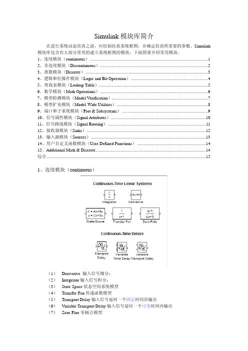
Simulink 模块库包含有大部分常用的建立系统框图的模块,下面简要介绍常用模块。
1、连续模块(continuous) (1)2、非连续模块(Discontinuous) (2)3、离散模块(Discrete) (3)4、逻辑和位操作模块(Logic and Bit Operation) (4)5、查找表模块(Lookup Table) (5)6.数学模块(Math Operations) (6)7、模型检测模块(Model Verification) (7)8、模型扩充模块(Model-Wide Utilities) (8)9、端口和子系统模块(Prot & Subsystems) (9)10、信号属性模块(Signal Attributes) (10)11、信号路线模块(Signal Routing) (11)12、接收器模块(Sinks) (12)13、输入源模块(Sources) (13)14、用户自定义函数模块(User-Defined Functions) (14)15、Additional Math & Discrete (14)综合 (15)1、连续模块(continuous)(1) Derivative 输入信号微分;(2) Integrator输入信号积分;(3) State-Space状态空间系统模型(4) Transfer-Fcn传递函数模型(5) Transport Delay输入信号延时一个固定时间再输出(6) Variable Transport Delay输入信号延时一个可变时间再输出(7) Zero-Ploe零极点模型2、非连续模块(Discontinuous)(1) Backlash间隙非线性(2) Coulomb&Viscous Friction库仑和粘度摩擦非线性(3) Dead Zone死区非线性(4)Dead Zone Dynamic动态死区非线性(5) Hit Crossing冲击非线性(6) Quantizer量化非线性(7) Rate Limiter静态限制信号的变化速率(8) Rate Limiter Dynamic动态限制信号的变化速率(9) Relay滞环比较器,限制输出值在某一范围内变化(10) Saturation饱和输出,让输出超过某一值是能够饱和(11) Saturation Dynamic动态饱和输出(12) Wrap To Zero3、离散模块(Discrete)(1) Difference差分环节(2) Discrete Derivative 离散微分环节(3) Discrete Filter 离散滤波器(4) Discrete State-Space 离散状态空间系统模型(5) Discrete Transfer Fcn 离散传递函数模型(6) Discrete Zero-Pole 以零极点表示的离散传递函数模型(7) Discrete-Time Integrator 离散时间积分器(8) First-Order Hold 一阶保持器(9) Integer Delay 整数被延迟(10) Memory 输出本模块上一步的输入值(11) Tapped Delay 延迟(12) Transfer Fcn First Order 离散一阶传递函数(13) Transfer Fcn Lead or Lag 传递函数(14) Transfer Fcn Real Zero 离散零点传递函数(15) Unit Delay 一个采样周期的延时(16) Weighted Moving Average 权值移动平均模型(17) Zero-Order Hold 零阶保持器4、逻辑和位操作模块(Logic and Bit Operation)(1) Bit Clear 位清零(2) Bit Set 位置位(3) Bitwise Operator 逐位操作(4) Combinatorial Logic 组合逻辑(5) Compare To Constant 和常量比较(6) Compare To Zero 和零比较(7) Detect Change 检测跳变(8) Detect Decrease 检测递减(9) Detect Fall Negative 检测负上升沿(10) Detect Fall Nonpositive 检测非负下降沿(11) Detect Increase 检测递增(12) Detect Rise Nonnegative 检测非负上升沿(13) Detect Rise Positive 检测正上升沿(14) Extract Bits 提取位(15) Interval Test 检测开区间(16) Interval Test Dynamic 动态检测开区间(17) Logical Operator 逻辑操作符(18) Relational Operator 关系操作符(19) Shift Arithmetic 移位运算5、查找表模块(Lookup Table)(1) Cosine 余弦函数查询表(2) Direct Lookup Table (n-D) n个输入信号的查询表(直接匹配)(3) Interpolation (n-D) using PreLookup n个输入信号的预插值(4) Lookup Table 输入信号的查询表(线性峰值匹配)(5) Lookup Table (2-D) 两维输入信号的查询表(线性峰值匹配)(6) Lookup Table (n-D) n维输入信号的查询表(线性峰值匹配)(7) Lookup Table Dynamic 动态查询表(8) PreLookup Index Search 预查询索引搜索(9) Sine 正弦函数查询表6.数学模块(Math Operations)(1) Abs 取绝对值(2) Add 加法(3) Algebraic Constraint 代数约束(4) Assignment 赋值(5) Bias 偏移(6) Complex to Magnitude-Angle 由复数输入转为幅值和相角输出(7) Complex to Real-Imag 由复数输入转为实部和虚部输出(8) Divide 除法(9) Dot Product 点乘运算(10) Gain 比例运算(11) Magnitude-Angle to Complex 由幅值和相角输入合成复数输出(12) Math Function 包括指数函数、对数函数、求平方、开根号等常用数学函数(13) Matrix Concatenation 矩阵级联(14) MinMax 最值运算(15) MinMax Running Resettable 最大最小值运算(16) Polynomial 多项式(17) Product 乘运算(18) Product of Elements 元素乘运算(19) Real-Imag to Complex 由实部和虚部输入合成复数输出(20) Reshape 取整(21) Rounding Function 舍入函数(22) Sign 符号函数(23) Sine Wave Function 正弦波函数(24) Slider Gain 滑动增益(25) Subtract 减法(26) Sum 求和运算(27) Sum of Elements 元素和运算(28) Trigonometric Function 三角函数,包括正弦、余弦、正切等(29) Unary Minus 一元减法(30) Weighted Sample Time Math 权值采样时间运算7、模型检测模块(Model Verification)(1) Assertion 确定操作(2) Check Discrete Gradient 检查离散梯度(3) Check Dynamic Gap 检查动态偏差(4) Check Dynamic Lower Bound 检查动态下限(5) Check Dynamic Range 检查动态范围(6) Check Dynamic Upper Bound 检查动态上限(7) Check Input Resolution 检查输入精度(8) Check Static Gap 检查静态偏差(9) Check Static Lower Bound 检查静态下限(10) Check Static Range 检查静态范围(11) Check Static Upper Bound 检查静态上限8、模型扩充模块(Model-Wide Utilities)(1) Block Support Table 功能快支持的表(2) DocBlock 文档模块(3) Model Info 模型信息(4) Timed-Based Linearization 时间线性分析(5) Trigger-Based Linearization 触发线性分析9、端口和子系统模块(Prot & Subsystems)(1) Configurable Subsystem 结构子系统(2) Atomic Subsystem 单元子系统(3) CodeReuseSubsystem 代码重用子系统(4) Enable 使能(5) Enabled and Triggered Subsystem 使能和触发子系统(6) Enabled Subsystem 使能子系统(7) For Iterator Subsystem 重复操作子系统(8) Function-Call Generator 函数响应生成器(9) Function-Call Subsystem 函数响应子系统(10) If 假设操作(11) If Action Subsystem 假设动作子系统(12) In1 输入端口(13) Model 模型(14) Out1 输出端口(15) Subsystem 子系统(16) Subsystem Examples 子系统例子(17) Switch Case 转换事件(18) Switch Case Action Subsystem 转换事件子系统(19) Trigger 触发操作(20) Triggered Subsystem 触发子系统(21) While Iterator Subsystem 重复子系统10、信号属性模块(Signal Attributes)(1) Data Type Conversion 数据类型转换(2) Data Type Conversion Inherited 继承的数据类型转换(3) Data Type Duplicate 数据类型复制(4) Data Type Propagation 数据类型继承(5) Data Type Propagation Examples 数据类型继承例子(6) Data Type Scaling Strip 数据类型缩放(7) IC 信号输入属性(8) Probe 探针点(9) Rate Transition 比率变换(10) Signal Conversion 信号转换(11) Signal Specification 信号特征说明(12) Weighted Sample Time 权值采样时间(13) Width 信号带宽11、信号路线模块(Signal Routing)(1) Bus Assignment 总线分配(2) Bus Creator 总线生成(3) Bus Selector 总线选择(4) Data Store Memory 数据存储(5) Data Store Read 数据存储读取(6) Data Store Write 数据存储写入(7) Demux 将一个复合输入转化位多个单一输出(8) Environment Controller 环境控制器(9) From 信号来源(10) Goto 信号去向(11) Goto Tag Visibility 标签可视化(12) Index Vector 索引向量(13) Manual Switch 手动选择开关(14) Merge 信号合并(15) Multiport Switch 多端口开关(16) Mux 将多个单一输入转化为一个复合输出(17) Selector 信号选择器(18) Switch 开关选择,当第二输入端大于临界值时,输出由第一个输入端而来,否则输出由第三输入端而来(1) Display 数字显示器(2) Floating Scope 浮动观察器(3) Out1 输出端口(4) Scope 示波器(5) Stop Simulation 仿真停止(6) Terminator 连接到没有连接到的输出端(7) To File 将输出数据写入数据文件保存(8) To Workspace 将输出数据写入Matlab的工作空间(9) XY Graph 显示二维图形(1) Band-Limited White Noise 带限白噪声(2) Chirp Signal 产生一个频率不断增大的正弦波(3) Clock 显示和提供仿真时间(4) Constant 常数信号(5) Counter Free-Running 无限计数器(6) Counter Limited 有限计数器(7) Digital Clock 在规定的采样间隔产生仿真时间按(8) From File 来自数据文件(9) From Workspace 来自Matlab的工作空间(10) Ground 连接到没有连接到的输入端(11) In1 输入信号(12) Pulse Generator 脉冲发生器(13) Ramp 斜坡信号输入(14) Random Number 产生正态分布的随机数(15) Repeating Sequence 产生规律重复的任意信号(16) Repeating Sequence Interpolated 重复序列内插值(17) Repeating Sequence Stair 重复阶梯序列(18) Signal Builder 信号创建器(19) Signal Generator 信号发生器,可以产生正弦波、方波、锯齿波及任意波形(20) Sine Wave 正弦波信号(21) Step 阶跃信号(22) Uniform Random Number 一致随机数14、用户自定义函数模块(User-Defined Functions)(1) Embedded MATLAB Function 嵌入的Matlab函数(2) Fcn 用自定义的函数(表达式)进行运算(3) Level-2 M-file S-Function M文件编写的S函数(4) MATLAB Fcn 利用Matlab的现有函数进行运算(5) S-Function 调用自编的S函数程序进行运算(6) S-Function Builder S函数建立器(7) S-Function Examples S函数例子15、Additional Math & Discrete(1) Additional Discrete(2) Additional Math: Increment – Decrement综合。
simulink模块库介绍

图 17
连续模块组
传递函数模块
状态方程模块 零极点增益模块 微分器、积分器、延迟、PID控制器
图18所示为弹簧—质量—阻尼器系统。图中,小车所 受外力为F,小车位移为x。设小车质量为m=1,弹簧 弹性系数k=3,阻尼系数f=4。设系统的初始状态设为 静止平衡点 x(0) x(0) 0 外力函数为幅值等于1的阶跃 量,仿真此小车的运动。
图2
图3
图4
图5
图6
2、信号合成与信号分离模块
mux和demux功能与总线信号生成和总线信号选 择模块近似。但是mux与demux是对所有信号进行合 成与分离的。 双击mux模块,在参数对话框将number of inputs 参数改为3。同样设置demux,将number of outputs 参数改为3。仿真结果如图8所示。
1、总线信号生成与总线信号选择模块
Bus creator用于将多个信号合成为一个总线信号; Bus selector选择总线信号的一个或多个。 如图2所示,有三种输入信号:正弦、阶跃、脉冲。 为便于观察,设置阶跃信号阶跃时间为1.2s,初始值 为0,终止值为0.5(如图3所示)。Bus creator输入 信号改为3(图4)。Bus selector选择信号1和3(图 5)。双击scope模块,再单击Parameters参数,将坐 标数改为2。最终运行效果如图6所示。
图 13
例:此系统可用如下方程表示
y 2 * u y 10 * u if t 5 if t 5
系统的输出只与当前的输入值有关,而且 随着仿真时间的继续在两个不同的代数方程之 间切换。
利用 Math 库中的 模块表示代数关系 和逻辑关系
simulink模块介绍
simulink模块介绍
Simulink是Matlab提供的一个功能强大的建模、仿真和代码生成工具,可用于模拟各种非线性系统。
它通过预先定义的图形化模块来建立系统仿真模型,每个模块代表一种信号处理功能,它们可以组合起来形成一个模型,并在模型上测量系统的动态特性。
1. 输入输出模块:提供了常量输入、示波器、数字量输入/输出模块等,用于将模拟或数字量信号输入和输出模拟系统;
2. 数学运算模块:提供了积分、微分、乘法、除法、求平方根、增补和求值等模块,用于实施数学运算;
3. 控制模块:提供了比较器、PID控制器、状态空间模型等模块,用于实现复杂的控制系统;
4. 编程模块:提供了MATLAB函数、S-Function、MATLAB程序、Stateflow等模块,可以在仿真模型中使用编程语言;
5. 动态模块:提供了直流电动机、永磁同步电动机、离心泵、液压缸、空气动力学等模块,用于仿真物理系统;
6. 逻辑模块:提供了逻辑门、映射器、比较器、时序器等模块,用于实现简单的逻辑控制功能;
7. 信号处理模块:提供了数字滤波器、信号积分、振荡器、数字放大器等模块,用于处理信号。
Simulink中的模块

Simulink 中的模块一:连续模块库(Continuous)1.积分模块(Integrator):功能:对输入变量进行积分。
说明:模块的输入可以是标量,也可以是矢量;输入信号的维数必须与输入信号保持一致。
2. 微分模块(Derivative)功能:通过计算差分A u/A t 近似计算输入变量的微分。
功能:用于建立一个预先指定的零点、极点,并用延迟算子s 表示的连续。
7.传输延迟模块(TransportDelay) 功能:用于将输入端的信号延迟指定的时间后再传输给输出信号8. 可变传输延迟模块(VariableTransportDelay) 功能:用于将输入端的信号进行可变时间的延迟。
二:离散模块库(Discrete)1 •零阶保持器模块(Zero-Order-Hold)功能:在一个步长内将输出的值保持在同一个值上。
2 .单位延迟模块(UnitDelay)功能:将输入信号作单位延迟,并且保持一个采样周期相当于时间算子z -1。
3•离散时间积分模块(DiscreteTimeIntegrator)功能:在构造完全离散的系统时,代替连续积分的功能。
使用的积分方法有:向前欧拉法向后欧拉法、梯形法。
6•离散传递函数模块(DiscreteTransferFcn)3. 线性状态空间模块(State-Space) 功能:用于实现以下数学方程描述的系统4. 传递函数模块(TransferFen) 功能:用执行一个线性传递函数。
5. 零极点传递函数模块(Zero-Pole)Ax y =Cx +Bu +Du4 •离散状态空间模块(DiscreteStateSpace)'功能:用于实现如下数学方程描述的系统:<5 •离散滤波器模块(DiscreteFilter) x[(n +1)T]=Ax(nT)+Bu(nT) 功能:用于实现无限脉冲响应(IIR )和有限脉冲响应T R)的数C 滤波器。
)+Du (nT )功能:用于执行一个离散传递函数。
simulink模块库介绍
信号滤波与变换
利用Simulink模块库中的滤波器设计、信号变换等 模块,可以对信号进行各种处理和分析,提取有用 信息。
信号检测与估计
Simulink模块库中的信号检测和估计模块可 以帮助用户对信号进行各种检测和估计,如 频率估计、相位估计等。
嵌入式系统设计
嵌入式处理器建模
Simulink模块库提供了嵌入式处理器建模模块, 用于对嵌入式处理器进行建模和仿真。
01
信号调制与解调
利用Simulink模块库中的信号调制和解 调模块,可以对通信信号进行调制和解 调,实现信号的传输和处理。
02
03
通信系统性能评估
Simulink模块库中的性能评估模块可 以帮助用户对通信系统的性能进行评 估和优化。
THANKS
感谢观看
地学习和使用这些工具。
丰富的非线性模型
非线性模块提供了丰富的非线性模型, 可以模拟各种非线性系统的行为,方 便用户进行系统分析和设计。
灵活的参数设置
非线性模块通常提供灵活的参数设置, 用户可以根据实际需求调整参数,以 获得更好的系统模拟效果。
通信系统模块
通信系统模块
这些模块用于设计和分析通信系统。 它们提供了各种通信协议、调制解调
使用MATLAB函数创建自定义模 块,需要编写MATLAB代码,并 将其封装为一个可调用的函数。
自定义模块可以通过Simulink的 MATLAB Function Block来实现, 该块允许用户在Simulink环境中 直接调用MATLAB函数。
使用Simulink块创建自定义模块
01
Simulink块是Simulink自带或 第三方提供的可重用组件,用 于实现各种信号处理、控制和 通信等功能。
SIMULINK的模块库介绍[指南]
![SIMULINK的模块库介绍[指南]](https://img.taocdn.com/s3/m/049a9a34bdd126fff705cc1755270722192e597a.png)
SIMULINK的模块库介绍(1)Commonly UsedBus Creator Create signal busBus Selector Select signals from incoming busConstant Generate constant valueData T ype Conversion Convert input signal to specified data typeDemux Extract and output elements of vector signalDiscrete-TimeIntegratorPerform discrete-time integration or accumulation of signal Gain Multiply input by constantGround Ground unconnected input portInport Create input port for subsystem or external input Integrator,IntegratorLimitedIntegrate signalLogical Operator Perform specified logical operation on inputMux Combine several input signals into vectorOutport Create output port for subsystem or external outputProduct Multiply and divide scalars and nonscalars or multiply and invert matricesRelational Operator Perform specified relational operation on inputs Saturation Limit range of signalScope and FloatingScopeDisplay signals generated during simulationSubsystem,AtomicSubsystem,NonvirtualSubsystem,CodeReuseSubsystemRepresent system within another systemSum,Add,Subtract,Sum of ElementsAdd or subtract inputsSwitch Switch output between first input and third input based on value of second inputT erminator Terminate unconnected output portUnit Delay Delay signal one sample period(2)ContinuousDerivative Output time derivative of inputIntegrator,IntegratorLimitedIntegrate signalPID Controller Simulate continuous-or discrete-time PID controllersPID Controller(2 DOF) Simulate continuous-or discrete-time two-degree-of-freedom PID controllersSecond-OrderIntegrator,Second-Order Integrator LimitedIntegrate input signal twiceState-Space Implement linear state-space systemTransfer Fcn Model linear system by transfer function Transport Delay Delay input by given amount of timeVariable TimeDelay,VariableTransport DelayDelay input by variable amount of timeZero-Pole Model system by zero-pole-gain transfer function(3)DiscontinuitiesBacklash Model behavior of system with playCoulomb and ViscousModel discontinuity at zero,with linear gain elsewhere FrictionDead Zone Provide region of zero outputDead Zone Dynamic Set inputs within bounds to zeroHit Crossing Detect crossing pointQuantizer Discretize input at specified intervalRate Limiter Limit rate of change of signalRate Limiter Dynamic Limit rising and falling rates of signalRelay Switch output between two constantsSaturation Limit range of signalSaturation Dynamic Bound range of inputWrap T o Zero Set output to zero if input is above threshold(4)DiscreteDifference Calculate change in signal over one time stepDiscrete Derivative Compute discrete time derivativeDiscrete Filter Model Infinite Impulse Response(IIR)direct form II filters Discrete FIR Filter Model FIR filtersDiscrete State-Space Implement discrete state-space systemDiscrete T ransfer Fcn Implement discrete transfer functionDiscrete Zero-Pole Model system defined by zeros and poles of discrete transfer function Discrete-TimeIntegratorPerform discrete-time integration or accumulation of signalFirst-Order Hold Implement first-order sample-and-holdInteger Delay Delay signal N sample periodsMemory Output input from previous time stepPID Controller Simulate continuous-or discrete-time PID controllersPID Controller(2 DOF) Simulate continuous-or discrete-time two-degree-of-freedom PID controllersT apped Delay Delay scalar signal multiple sample periods and output all delayed versionsTransfer Fcn FirstOrderImplement discrete-time first order transfer functionTransfer Fcn Lead orLagImplement discrete-time lead or lag compensatorTransfer Fcn RealZeroImplement discrete-time transfer function that has real zero and no pole Unit Delay Delay signal one sample periodZero-Order Hold Implement zero-order hold of one sample period(5)Logic and BitOperationsBit Clear Set specified bit of stored integer to zeroBit Set Set specified bit of stored integer to oneBitwise Operator Specified bitwise operation on inputs Combinatorial Logic Implement truth tableCompare T o Constant Determine how signal compares to specified constant Compare T o Zero Determine how signal compares to zeroDetect Change Detect change in signal valueDetect Decrease Detect decrease in signal valueDetect Fall Negative Detect falling edge when signal value decreases to strictly negative value,and its previous value was nonnegativeDetect Fall Nonpositive Detect falling edge when signal value decreases to nonpositive value,and its previous value was strictly positiveDetect Increase Detect increase in signal valueDetect Rise Nonnegative Detect rising edge when signal value increases to nonnegative value,and its previous value was strictly negativeDetect Rise Positive Detect rising edge when signal value increases to strictly positive value,and its previous value was nonpositiveExtract Bits Output selection of contiguous bits from input signal Interval T est Determine if signal is in specified intervalInterval T est Dynamic Determine if signal is in specified intervalLogical Operator Perform specified logical operation on input Relational Operator Perform specified relational operation on inputs Shift Arithmetic Shift bits or binary point of signal(6)Lookup T ablesDirect LookupT able(n-D)Index into N-dimensional table to retrieve element,column,or 2-D matrixInterpolation Using Prelookup Use precalculated index and fraction values to accelerate approximation of N-dimensional functionLookup T able Approximate one-dimensional functionLookup T able(2-D) Approximate two-dimensional functionLookup T able(n-D) Approximate N-dimensional functionLookup T ableDynamicApproximate one-dimensional function using dynamic table Prelookup Compute index and fraction for Interpolation Using Prelookup blockSine,Cosine Implement fixed-point sine or cosine wave using lookup table approach that exploits quarter wave symmetry(7)Math OperationsAbs Output absolute value of inputAlgebraic Constraint Constrain input signal to zeroAssignment Assign values to specified elements of signalBias Add bias to inputComplex toMagnitude-AngleCompute magnitude and/or phase angle of complex signal Complex to Real-Imag Output real and imaginary parts of complex input signalDivide Divide one input by anotherDot Product Generate dot product of two vectorsFind Find nonzero elements in arrayGain Multiply input by constantMagnitude-Angle toComplexConvert magnitude and/or a phase angle signal to complex signal Math Function Perform mathematical functionMatrix Concatenate,V ector Concatenate Concatenate input signals of same data type to create contiguous output signalMinMax Output minimum or maximum input valueMinMax RunningResettableDetermine minimum or maximum of signal over time Permute Dimensions Rearrange dimensions of multidimensional array dimensions Polynomial Perform evaluation of polynomial coefficients on input valuesProduct Multiply and divide scalars and nonscalars or multiply and invert matricesProduct of Elements Copy or invert one scalar input,or collapse one nonscalar input Real-Imag to Complex Convert real and/or imaginary inputs to complex signalReshape Change dimensionality of signalRounding Function Apply rounding function to signalSign Indicate sign of inputSine Wave Function Generate sine wave,using external signal as time sourceSlider Gain V ary scalar gain using sliderSqrt,SignedSqrt,Reciprocal SqrtCalculate square root,signed square root,or reciprocal of square root Squeeze Remove singleton dimensions from multidimensional signal Sum,Add,Subtract,Sum of ElementsAdd or subtract inputsTrigonometricFunctionSpecified trigonometric function on inputUnary Minus Negate inputWeighted SampleTime MathSupport calculations involving sample time(8)Model VerificationAssertion Check whether signal is zeroCheck Discrete Gradient Check that absolute value of difference between successive samples of discrete signal is less than upper boundCheck Dynamic Gap Check that gap of possibly varying width occurs in range of signal's amplitudesCheck DynamicLower BoundCheck that one signal is always less than another signalCheck Dynamic Range Check that signal falls inside range of amplitudes that varies from time step to time stepCheck Dynamic UpperBoundCheck that one signal is always greater than another signal Check InputResolutionCheck that input signal has specified resolutionCheck S tatic Gap Check that gap exists in signal's range of amplitudesCheck Static Lower Bound Check that signal is greater than(or optionally equal to)static lower boundCheck S tatic Range Check that signal falls inside fixed range of amplitudesCheck Static UpperBoundCheck that signal is less than(or optionally equal to)static upper bound(9)Model-WideUtilitiesBlock Support T able View data type support for Simulink blocksDocBlock Create text that documents model and save text with modelModel Info Display revision control information in modelTimed-BasedGenerate linear models in base workspace at specific times LinearizationTrigger-BasedGenerate linear models in base workspace when triggered Linearization(10)Ports&SubsystemsTrigger Add trigger port to model or subsystemAction Port Implement Action subsystems used by if and switch control flow statements in Simulink softwareConfigurableSubsystemRepresent any block selected from user-specified library of blocks Enable Add enabling port to subsystemEnabled and Triggered Subsystem Represent subsystem whose execution is enabled and triggered by external inputEnabled Subsystem Represent subsystem whose execution is enabled by external inputFor Each Enable blocks inside For Each Subsystem to process elements or subarrays of input signal independentlyFor Each Subsystem Repeatedly perform algorithm on each element or subarray of input signal and concatenate resultsFor Iterator Repeatedly execute contents of subsystem at current time step until iteration variable exceeds specified iteration limitFor Iterator Subsystem Represent subsystem that executes repeatedly during simulation time stepFunction-Call Generator Execute function-call subsystem specified number of times at specified rateFunction-Call Split Provide junction for splitting function-call signalFunction-CallSubsystemRepresent subsystem that can be invoked as function by another block If Model if-else control flowIf Action Subsystem Represent subsystem whose execution is triggered by If blockInport Create input port for subsystem or external inputModel Include model as block in another modelOutport Create output port for subsystem or external outputSubsystem,AtomicSubsystem,NonvirtualSubsystem,CodeReuseSubsystemRepresent system within another systemSwitch Case Implement C-like switch control flow statementSwitch Case ActionSubsystemRepresent subsystem whose execution is triggered by Switch Case block Triggered Subsystem Represent subsystem whose execution is triggered by external inputWhile Iterator Subsystem Represent subsystem that executes repeatedly while condition is satisfied during simulation time step(11)Signal AttributesSignal Specification Specify desired dimensions,sample time,data type,numeric type,and other attributes of signalBus to V ector Convert virtual bus to vectorData T ype Conversion Convert input signal to specified data typeData T ype Conversion Inherited Convert from one data type to another using inherited data type and scalingData T ype Duplicate Force all inputs to same data typeData T ype Propagation Set data type and scaling of propagated signal based on information from reference signalsData T ype ScalingStripRemove scaling and map to built in integer IC Set initial value of signalProbe Output signal's attributes,including width,dimensionality,sample time,and/or complex signal flagRate T ransition Handle transfer of data between blocks operating at different rates Signal Conversion Convert signal to new type without altering signal values Weighted SampleTimeSupport calculations involving sample timeWidth Output width of input vector(12)Signal RoutingBus Assignment Replace specified bus elementsBus Creator Create signal busBus Selector Select signals from incoming busData Store Memory Define data storeData Store Read Read data from data storeData Store Write Write data to data storeDemux Extract and output elements of vector signalEnvironment Controller Create branches of block diagram that apply only to simulation or only to code generationFrom Accept input from Goto blockGoto Pass block input to From blocksGoto T ag Visibility Define scope of Goto block tagIndex Vector Switch output between different inputs based on value of first input Manual Switch Switch between two inputsMerge Combine multiple signals into single signalMultiport Switch Choose between multiple block inputsMux Combine several input signals into vectorSelector Select input elements from vector,matrix,or multidimensional signalSwitch Switch output between first input and third input based on value of second input(13)SinksDisplay Show value of inputOutport Create output port for subsystem or external output Scope and FloatingDisplay signals generated during simulationScopeStop Simulation Stop simulation when input is nonzeroT erminator Terminate unconnected output portT o File Write data to fileT o Workspace Write data to MA TLAB workspaceXY Graph Display X-Y plot of signals using MA TLAB figure window (14)SourcesBand-Limited WhiteNoiseIntroduce white noise into continuous system Chirp Signal Generate sine wave with increasing frequency Clock Display and provide simulation time Constant Generate constant valueCounter Free-Running Count up and overflow back to zero after reaching maximum value for specified number of bitsCounter Limited Count up and wrap back to zero after outputting specified upper limit Digital Clock Output simulation time at specified sampling interval Enumerated Constant Generate enumerated constant valueFrom File Read data from MA T-fileFrom Workspace Read data from workspaceGround Ground unconnected input portInport Create input port for subsystem or external inputPulse Generator Generate square wave pulses at regular intervalsRamp Generate constantly increasing or decreasing signalRandom Number Generate normally distributed random numbersRepeating Sequence Generate arbitrarily shaped periodic signalRepeating Sequence Interpolated Output discrete-time sequence and repeat,interpolating between data pointsRepeating SequenceStairOutput and repeat discrete time sequenceSignal Builder Create and generate interchangeable groups of signals whose waveforms are piecewise linearSignal Generator Generate various waveformsSine Wave Generate sine wave,using simulation time as time source Step Generate step functionUniform RandomNumberGenerate uniformly distributed random numbers(15)User-DefinedFunctionsEmbedded MATLABInclude MA TLAB code in models that generate embeddable C code FunctionFcn Apply specified expression to inputLevel-2 M-FileUse Level-2 M-file S-function in modelS-FunctionMATLAB Fcn Apply MA TLAB function or expression to inputS-Function Include S-function in modelS-Function Builder Create S-function from C code that you provide(16)AdditionalMath&DiscreteAdditional Discrete Provide additional discrete math supportAdditional Increment or decrement value of signal by oneMath:Increment—Dec rement。
simulink模块库使用说明
simulink模块库使用说明Simulink模块库使用说明。
一、Simulink模块库是啥。
Simulink模块库就像是一个超级大的玩具箱,里面装满了各种各样超级酷的小零件,这些小零件就是模块啦。
对于咱们大学生来说,特别是那些学工科的小伙伴,这个模块库简直就是宝藏。
它能让我们把那些复杂的数学模型、控制系统啥的,用一种超级直观的方式搭建起来,就像搭积木一样好玩。
这个模块库涵盖了好多不同类型的模块呢。
比如说,有专门处理数学运算的模块,像加法、减法、乘法、除法这些基本运算的模块,还有更复杂的三角函数、对数函数之类运算的模块。
这就好比是我们数学工具包里的各种小工具,需要做什么运算,就把对应的模块拿出来用就好啦。
还有一些和信号处理相关的模块。
信号这个东西在很多学科里都很重要呢,像通信工程专业的同学肯定特别熟悉。
在Simulink里,有能产生各种信号的模块,像正弦波信号、方波信号之类的,也有对信号进行滤波、放大、调制解调等操作的模块。
这就像是一个信号处理的小工厂,我们可以根据自己的需求把这些模块组合起来,让信号按照我们想要的方式变化。
二、常用模块的使用。
1. 源模块。
源模块就像是水流的源头一样,它是信号的起始点。
比如说,前面提到的正弦波信号模块就属于源模块。
使用这个模块特别简单,只要把它拖到我们的Simulink模型编辑界面里,然后就可以在它的参数设置里调整一些参数,像正弦波的幅值、频率、相位这些。
这就好比是我们在调整水龙头的水流大小和水温一样,根据我们的需求把这些参数设置好,就能得到我们想要的正弦波信号啦。
2. 运算模块。
运算模块的使用也很有趣。
就拿加法模块来说吧,我们把它拖到界面里,然后就可以把需要相加的信号连接到这个模块的输入端口上。
一般来说,加法模块有两个输入端口,就像两只手一样,分别抓住两个要相加的信号,然后在它的输出端口就会输出这两个信号相加之后的结果啦。
而且,这些模块的大小和颜色都可以根据我们的喜好调整哦,是不是很人性化呢?3. 显示模块。
SIMULINK的模块库介绍

SIMULINK的模块库介绍SIMILINK模块库按功能进行分为以下8类子库:Continuous(连续模块)Discrete(离散模块)Function&Tables(函数和平台模块)Math(数学模块)Nonlinear(非线性模块)Signals&Systems(信号和系统模块)Sinks(接收器模块)Sources(输入源模块)连续模块(Continuous)continuous.mdlIntegrator:输入信号积分Derivative:输入信号微分State-Space:线性状态空间系统模型Transfer-Fcn:线性传递函数模型Zero-Pole:以零极点表示的传递函数模型Memory:存储上一时刻的状态值Transport Delay:输入信号延时一个固定时间再输出Variable Transport Delay:输入信号延时一个可变时间再输出离散模块(Discrete) discrete.mdlDiscrete-time Integrator:离散时间积分器Discrete Filter:IIR与FIR滤波器Discrete State-Space:离散状态空间系统模型Discrete Transfer-Fcn:离散传递函数模型Discrete Zero-Pole:以零极点表示的离散传递函数模型First-Order Hold:一阶采样和保持器Zero-Order Hold:零阶采样和保持器Unit Delay:一个采样周期的延时函数和平台模块(Function&Tables) function.mdlFcn:用自定义的函数(表达式)进行运算MATLAB Fcn:利用matlab的现有函数进行运算S-Function:调用自编的S函数的程序进行运算Look-Up Table:建立输入信号的查询表(线性峰值匹配)Look-Up Table(2-D):建立两个输入信号的查询表(线性峰值匹配)数学模块( Math ) math.mdlSum:加减运算Product:乘运算Dot Product:点乘运算Gain:比例运算Math Function:包括指数函数、对数函数、求平方、开根号等常用数学函数Trigonometric Function:三角函数,包括正弦、余弦、正切等MinMax:最值运算Abs:取绝对值Sign:符号函数Logical Operator:逻辑运算Relational Operator:关系运算Complex to Magnitude-Angle:由复数输入转为幅值和相角输出Magnitude-Angle to Complex:由幅值和相角输入合成复数输出Complex to Real-Imag:由复数输入转为实部和虚部输出Real-Imag to Complex:由实部和虚部输入合成复数输出非线性模块( Nonlinear ) nonlinear.mdlSaturation:饱和输出,让输出超过某一值时能够饱和。
- 1、下载文档前请自行甄别文档内容的完整性,平台不提供额外的编辑、内容补充、找答案等附加服务。
- 2、"仅部分预览"的文档,不可在线预览部分如存在完整性等问题,可反馈申请退款(可完整预览的文档不适用该条件!)。
- 3、如文档侵犯您的权益,请联系客服反馈,我们会尽快为您处理(人工客服工作时间:9:00-18:30)。
1、总线信号生成与总线信号选择模块
Bus creator用于将多个信号合成为一个总线信号; Bus selector选择总线信号的一个或多个。
如图2所示,有三种输入信号:正弦、阶跃、脉冲。 为便于观察,设置阶跃信号阶跃时间为1.2s,初始值 为0,终止值为0.5(如图3所示)。Bus creator输入 信号改为3(图4)。Bus selector选择信号1和3(图 5)。双击scope模块,再单击Parameters参数,将坐 标数改为2。最终运行效果如图6所示。
图7 图8
3、数据类型转换模块
Data type conversion 可将输入数据类型转换为 指定输出类型。具体选择有:inherit(与输入数据保 持一致)、double、single、int8等。同时可以选择取 整方向。Zero:向零取整;nearest:向最接近整数取 整;floor:向负无穷取整;ceiling:向正无穷取整。
图2
图3
图4图5 图6源自2、信号合成与信号分离模块
mux和demux功能与总线信号生成和总线信号选 择模块近似。但是mux与demux是对所有信号进行合 成与分离的。
双击mux模块,在参数对话框将number of inputs 参数改为3。同样设置demux,将number of outputs 参数改为3。仿真结果如图8所示。
图 13
例:此系统可用如下方程表示
y 2 * u if t 5
y
10
*
u
if t 5
系统的输出只与当前的输入值有关,而且
随着仿真时间的继续在两个不同的代数方程之 间切换。
利用 Math 库中的 模块表示代数关系 和逻辑关系
利用 Signal Routing 库 中的开关和限幅模块实 现开关和限幅动作
图 16
8、增益、输入、输出及终端模块
Gain可用来设置信号的放大倍数;in1(输入) 在建子系统时作为信号的输入接口; out1(输 出)在建子系统时作为信号的输出接口;终端 (Terminator)可用来连接没有与其它模块连接的 输出端口。
6.2连续系统模块库
严格说来,一个具体的物理系统通常都是非线性 系统,而且是以分布参数的形式存在的,但是由这样 的非线性系统建立的数学模型,在需要求解非线性方 程和偏微分方程时,是非常困难的。因此,在误差允 许的范围内,可以将非线性模型线性化,或者直接用 线性集总参数模型描述物理系统。
Simulink中的Continuous模块库提供了适用于建 立线性连续系统的模块,包括积分器模块、传递函数 模块、状态空间模块和零-极点模块等,这些模块为用 户以不同形式建立线性连续系统模型提供了方便,如 图17所示。
图 17
连续模块组
传递函数模块
状态方程模块 零极点增益模块
微分器、积分器、延迟、PID控制器
4、积分模块
Integrator模块为连续时间积分单元。双击图9中 该模块,在initial condition可设置积分其初始值,在 limit output可设置输出最大和最小值。仿真运行结果 如图10所示。
图9
图 10
5、离散时间积分模块
Discrete time integrator(离散时间积分),可完 成离散系统积分作用。如图11所示,双击离散积分模 块,设置gainvalue(积分增益值),改变积分速度。 在sample time文本框可设置离散积分采样时间,如设 置为-1,表示与输入信号采样时间一致。在limit output可设置积分输出上下限。在图11中设置 Discrete time integrator1模块增益值为2,采样时间为 0.5,仿真结果如图12所示。
图18所示为弹簧—质量—阻尼器系统。图中,小车所 受外力为F,小车位移为x。设小车质量为m=1,弹簧 弹性系数k=3,阻尼系数f=4。设系统的初始状态设为 静止平衡点 x(0) x(0) 0 外力函数为幅值等于1的阶跃 量,仿真此小车的运动。
f
x
m F
k
图 18
解法1: 构建常微分方程
根据牛顿运动定律,得到小车的运动方程
图 14
图 15
这里使用Signal Routing模块库中的Switch模块 实现切换功能。Switch模块有三个输入端口,它根据 第二个输入端口(中间的输入)的值来判断输出第一个 输入端口(最上面的端口)或第三个输入端口(最下面的 端口)的值,因此,第一个输入和第三个输入被称为数 据输入,而第二个输入则被称为控制输入。图16是 Switch模块的参数对话框。
第六章 simulink模块库 介绍
6.1常用模块库
图 1 常用模块库
初学simulink,常用模块
(commonly used blocks)使用最为频繁。 在Simulink浏览器中, 单击左侧“commonly used blocks”节点,可打 开常用模块库。
常用模块库包括:Bus creator(总线信号产生 器),commonly bus selector(常用总线信号选择 器),constant(常数模块),data type conversation (数据类型转换),demux(信号分离器),mux(信号 合成器),gain(增益)等。
kx fx mx F
将相关参数代入上式得
x 4x 3x F
将上述微分方程改写为
式中 u(t) F
x u(t) 4x 3x
利用积分模块构建simulink模块
u(t)
x’’
x’
x
图 19
小车位移随时间的变化
图 20
解法2: 利用传递函数
图 11
图 12
6、乘法与加法模块
product乘法器模块用以求输入信号的乘积, 双击模块可设置端口数。Sum模块用来求输入 信号的加、减。在list of signs可设置加减法符 号。在Icon shape列表可修改其外形。
7、关系操作及逻辑操作模块
Relation operator关系操作模块可用来比 较两个输入信号的大小关系。Logic operator逻 辑操作模块可用来求两输入变量的逻辑操作。