TP.VST59S.PB813
WY8S8003系列ISP用户手册说明书
WY8S8003系列ISP用户手册Ver1.0.1上海维安半导体有限公司Wayon Semiconductor Co.,Ltd.目录1.概述 (1)1.1.软件简介 (1)1.2.MCU与下载盒连接示意图 (1)1.3.ISP升级流程 (2)1.3.1.一键下载 (2)1.3.2.普通下载 (7)2.通信协议 (11)2.1.命令列表 (11)2.2.串口协议格式 (11)2.2.1.下载命令请求协议定义 (11)2.2.2.下载命令回复协议定义 (12)2.3.指令说明 (12)2.3.1.CMD_SYNC (12)2.3.2.CMD_UPDATE_APROM (13)2.3.3.CMD_UPDATE_APROM_END (13)3.软件基本说明 (15)3.1.软件安装 (15)3.2.软件界面说明 (15)4.修订历史 (16)1. 概述ISP 是在系统编程的缩写,这个功能可以让用户在软件控制下,不需要将MCU 从产品上取下来进行应用程序升级。
针对8051 MCU 产品,我们通过串口提供ISP 升级方法,用户需要在LDROM 区域下载BOOT 程序。
将MCU 调试下载器或其他串口工具和MCU 相连接,并利用WayOn ISP Programer Tool 软件完成升级。
1.1.软件简介WayOn ISP Programer Tool 是维安半导体有限公司针对8051系列MCU 开发的ISP 下载工具,配合8051 MCU 调试器支持一键下载功能。
工具支持UART 通讯方式,默认采用38400的波特率,下载文件支持BIN/HEX 格式,BOOT 程序支持的串口管脚RXD 为引脚P04,TXD0为引脚P05,RST 引脚为P20。
维安8051 MCU 支持默认从APROM 启动,配合维安调试器的串口和GPIO 管脚连接目标MCU 串口和P20(P20配置为RST ),完成ISP 升级。
同时支持默认选择从LDROM 启动,利用普通串口连接目标MCU 串口,在上电启动周期(客户可配)之内完成升级启动完成ISP 升级。
TP-LINK IPTV解决方案

无线共享上网一体机 TD-W89741N 增强型 (经济型)
增强型防雷设计,4000V 雷击测试 支持同时共享上网与 IPTV 连接 11N 技术,150M 无线传输速率 IP 带宽控制,自由分配上网带宽 支持 PVC 自动检测
增强型防雷设计,4000V 雷击测试 支持同时共享上网与 IPTV 连接
无辐射,低功耗,绿色节能
电力线 AP
无线网卡 有线共享上网一体机 无线共享上网一体机
(增强型)
TL-PWA2701
TL-WN723N TL-WN727N TD-89402 增强型
TD-W89841N 增强型
200Mbps 传输速率,150Mbps 无线传输速率 128-bit AES 加密,数据传输安全可靠 同一电表范围内,传输距离可达 300m 支持 QoS 应用优先,保障 IPTV 的畅通
类型型号特点电力线适配器增强型tlpa501500mbps传输速率信号稳定不掉线128bitaes加密数据传输安全可靠同一电表范围内传输距离可达300m支持qos应用优先保障iptv的畅通支持多路iptv电力线适配器经济型tlpa200200mbps传输速率信号稳定128bitaes加密数据传输安全可靠同一电表范围内传输距离可达300m无辐射低功耗绿色节能电力线aptlpwa2701200mbps传输速率150mbps无线传输速率128bitaes加密数据传输安全可靠同一电表范围内传输距离可达300m支持qos应用优先保障iptv的畅通无线网卡tlwn723ntlwn727n11n无线技术150mbps无线传输速率qss快速安全设置无线网络更安全精致小巧方便用于机顶盒有线共享上网一体机td89402增强型ip带宽控制自由分配上网带宽支持pvc自动检测增强型防雷设计4000v雷击测试支持同时共享上网与iptv连接无线共享上网一体机增强型tdw89841n增强型11n技术300m无线传输速率ip带宽控制自由分配上网带宽支持pvc自动检测增强型防雷设计4000v雷击测试支持同时共享上网与iptv连接无线共享上网一体机经济型tdw89741n增强型11n技术150m无线传输速率ip带宽控制自由分配上网带宽支持pvc自动检测增强型防雷设计4000v雷击测试支持同时共享上网与iptv连接2
MC51F8124 用户手册说明书

MC51F8124晟矽微电本公司保留对以下所有产品在可靠性、功能和设计方面的改进作进一步说明的权利。
MC51F8124 用户手册 V1.7 8位增强型8051单片机主要特性CORE✧ 1T 高速增强型8051内核 ✧ 双DPTR ROM✧ 片上16K 字节 FLASH ,擦写10万次以上✧ 片上1024字节 E2(EEPROM),擦写10万次以上 ✧ 支持代码分区保护功能(有效防止非法读/写/擦) ✧ 支持FLASH 和E2在电路编程(ICP ), 支持E2在应用编程(IAP ) RAM✧ 片上1536(256+1280)字节 SRAM 时钟源✧ 片上高精度32MHz 高速振荡器(常温5.0V 电压下±1%精度;全工作条件下±5%精度)✧ 片上32KHz 超低功耗低速振荡器,供看门狗定时器和T3使用✧ 外部可选接32768Hz 晶体振荡器 电源管理模式✧ 4种工作模式:高速/低速/停止/休眠✧ 增加高级能耗控制功能,满足用户低功耗的需求 复位✧ 上电复位(POR )/外部复位/低电压复位(LVR )/看门狗复位/软件复位✧ LVR 电压4级可选:2.1V 、2.5V 、3.5V 、4.1V ✧ 看门狗复位可选8种溢出时间 I/O✧ 最多26个双向通用I/O 口(28PIN 封装下) ✧ 支持3种输入/输出模式,支持输入上拉电阻配置 ✧ 14个IO 具备独立大电流驱动能力✧ 24个I/O 可软件模拟成1/2 BIAS 的LCD COM 口 定时器/计数器✧ 2个16位T0/T1定时器,兼容标准8051✧ 1个16位增强型T2定时器,兼容8052的T2,带输入捕获和输出比较功能 ✧ 1个16位T3时基定时器,可连接外部32768Hz 晶振,在停止/休眠模式下可定时唤醒 PWM 定时器✧ 1路独立8位PWM0,可作通用定时器✧ 3组共6路16位PWM1阵列,可互补输出且死区时间可调,并具有故障保护中断功能✧ PWM1可在选片上高速时钟或其分频下独立工作 12位高精度ADC✧ 12位高精度逐次逼近型ADC✧ 14通道:外部12通道+内部2通道✧ 参考电压可选:内部2.0V 、VDD 、Vref 引脚输入 2路UART✧ 2路UART 模块,可兼容8051标准✧ 增强UART0支持“帧出错”检测及自动地址识别 ✧ 支持8位同步半双工、8位/9位异步全双工等4种工作方式 SPI✧ 支持全双工,3线/4线同步模式,主/从机可选 ✧ 支持主机模式错误用以防止主机冲突 TK 触摸按键✧ 最大支持16通道的高灵敏触摸按键✧ 支持4MHz/2MHz/1MHz/500KHz 四种工作频率 ✧ 支持可选基准电压,支持触摸按键扫描中断,支持触摸按键唤醒 中断✧ INT0X 、T0、INT1X 、T1、UART0、TK 、ADC 、T2、SPI 、PWM1、PWM0、PWM1FB 、UART1、CRC 、T3共15个中断源 ✧ 2级中断优先级可设 ✧ 其中INTnx (n=0~1,x=0~4)支持多重映射输入,5选1分别对应两个中断源(INT0x/INT1x );支持上升沿触发方式和高电平脉宽测量功能 循环冗余校验算法模块(符合CRC-16标准) 双两线调试与编程接口✧ 两组调试和编程接口任意二选一,支持自动识别 开发工具兼容KEIL TM 集成开发环境 工作电压✧ 2.0V ~5.5V 工作环境温度 ✧ -40℃~85℃ 封装形式 ✧ SOP28、SSOP28、SOP24、SSOP24、SOP20、TSSOP201T 8051内核FLASH 型MCU ,16KB FLASH ROM ,1536B SRAM ,1KB 独立EEPROM ,12位高速ADC ,16通道高灵敏触摸电路,6通道16位PWM ,8位PWM ,4个16位定时器,2路UART ,SPI ,CRC ,双两线调试1产品简介1.1概述本产品是一款高速低功耗1T周期8051内核8位增强型FLASH微控制器芯片,较传统8051相比,运行效率更高。
H3C无线控制器
华三--H3C无线控制器与无线终端设备H3C WX5002无线控制器与中端交换机用插板EWP-WX5002-64-H32端口千兆Combo无线控制器(支持64AP)LIS-WX-32无线控制器license费用-管理32APEWP-WX5004-H3H3C WX5004-4端口千兆Combo无线控制器LSKM2150A150W 交流电源模块LSWM1WCM10H3C S5800 系列-无线功能模块-OSM SlotLSWM1WCM20H3C S58 系列-无线功能模块-接口模块扩展插槽LSPM2150D H3C S5500 150W 直流电源模块H3C WX6103无线控制器与插板模块EWP-WX6103-H3H3C WX6103 无线控制器主机LSQM1WCMB0S7500E 无线控制器业务板模块EWPXM1WCMB0WX6103 无线控制器主控板模块EWPXM1G24XA024端口千兆无线控制器接口板(Combo+Slot插槽) EWPXM1FWA0H3C WX6103-EWPXM1FWA0-无线安全业务板模块LSRM1WCM2A1S9500E 无线控制器业务板H3C WX6103无线控制器配置模块LSQM1AC650H3C PSR650A 交流电源模块,650WLSQM1DC650H3C PSR650D 直流电源模块,650WEWPXM1XP2P H3C WX6103-2端口万兆以太网XFP光接口模块EWPXM1XP1P H3C WX6103-1端口万兆以太网XFP光接口模块LIS-WX-128无线控制器license费用-管理128APH3C WA1208E-主机EWP-WA1208E-GP无线局域网单G模块大功率接入点EWP-WA1208E-GP-FIT无线局域网单G模块大功率接入点-FITH3C无线局域网接入点设备EWP-WA2110-AG-FIT H3C WA2110-AG-无线局域网AG双模单频可管理型接入点-FIT H3C WA2200-主机EWP-WA2210-AG H3C WA2210-AG 无线局域网室内型AG单频双模接入点EWP-WA2220-AG H3C WA2220-AG 无线局域网室内型AG双频双模接入点EWP-WA2220E-AG H3C WA2220E-AG 无线局域网增强型AG双频双模接入点H3C WA2220X-AGP 无线局域网室外型AG双频双模2.4GHz大功EWP-WA2220X-AGP率接入点EWP-WA2220E-AG-T H3C WA2220E-AG-T-车载无线接入点(MR)H3C WA2210X-GE-无线局域网室外增强型802.11b/g单频双模EWP-WA2210X-GE接入点EWP-WA2220X-AGE H3C WA2220X-AGE-无线局域网室外增强型AG双频双模接入点H3C WA2210E-GE,无线局域网增强型802.11b/g单频双模接入EWP-WA2210E-GE点EWP-WB2320X-AGE H3C WB2320X-AGE,无线网桥设备EWP-WA2200-WOU H3C WA2200-无线局域网接入点室外单元模块EWP-WA2210-AG-FIT H3C WA2210-AG 无线局域网室内型AG单频双模接入点-FIT EWP-WA2220-AG-FIT H3C WA2220-AG 无线局域网室内型AG双频双模接入点-FIT EWP-WA2210X-GE-FIT H3C WA2210X-GE-无线局域网室外增强型802.11b/g单频双模接入点-FITEWP-WA2220X-AGP-FITH3C WA2220X-AGP 无线局域网室外型AG双频双模2.4GHz大功率接入点-FITEWP-WA2220X-AGE-FITH3C WA2220X-AGE-无线局域网室外增强型AG双频双模接入点-FITEWP-WA2210E-GE-FITH3C WA2210E-GE-无线局域网增强型802.11b/g单频双模接入点-FITEWP-WA2220E-AG-FIT H3C WA2220E-AG 无线局域网增强型AG双频双模接入点-FIT EWP-WB2320X-AGE-FIT H3C WB2320X-AGE-无线网桥设备-FITEWP-WH2530X-DAG-FIT H3C WH2530X-DAG-无线Mesh设备-FITH3C 无线局域网2.4GHz天线组件-全向&定向天线-802.11b/gTQJ-SA800/2500-3全向天线-824~960/1710~2500MHz-3dBi-垂直-360DEG-50W-0r-N(F)-是TQJ-2400-11-T2全向天线-2400-2500MHz-11dBi-垂直极化-150W-2r-N型母头-自带支架TDJ-SA2400-11-90定向天线-2400~2500MHz-11dBi-90deg-Vertical--0r-300W-with support-N(female)-0.28mTQJ-2400BKF-Y定向天线-2.4~2.483GHz-8.5dBi-80度-垂直极化-50W-N-K-否SL13090A全向天线-2.4~2.5GHz-5dBi-垂直极化-全向-10W-N-K-否TQC-2400CI全向天线-2.4~2.483GHz-5.5dBi-垂直极化-50W-SMA-RP-否TDJ-2400IA(-45)定向天线,2.4~2.5GHz,15dBi,72deg,负45度,100W,N-K,是SL14011A定向天线,2.4~2.5GHz,15±1dBi,30±3deg,垂直极化,100W,N-K,否定向天线,2.4~2.5GHz,10±1dBi,55±3deg,垂直极SL14166A化,100W,N-K,否H3C 无线局域网5.8GHz天线组件-全向&定向天线-802.11a定向天线-5725~5850MHz-17dBi-25deg-垂直TDJ-DBS5800-17-50W-0r-N-Female-自带支架全向天线-5725~5850MHz-12dBi-垂直TQJ-5800-12-T0-12dBi-5W-0r-N(female)-自带支架定向天线-5.725~5.85GHz-29dBi-6度-垂直或水平-100W-N-K-TDJ-5800P6否全向天线-5.725~5.875GHz-5dBi-垂直极化-全向-100W-N-K-SL13089A否定向天线-2.4~2.5&5.15~5.85GHz-12&15dBi-45&20度-垂直极TDJ-2458BKC化-50W-N-K-否定向天线-2.4~2.5&5.15~5.85GHz-2.5&4.5dBi-360度-垂直极TQJ-2458XTJ1化-50W-N-K-否TDJ-5158BKT60-2定向天线-5150-5850MHz-17dBi-60°-垂直极化-50W-N型H3C 无线终端设备发货附件一次电源-0degC-40degC-100V-240V-48V/0.5A-AC电源线可拆FSP025-1AD207A卸CAB-PGND-Pwr-3m外部电源线-机箱PGND-12AWG-3m-(OT6-4)CAB-RF-0.2m-SMA射频电缆-0.2m-(SFF50-3)-(N50直公 to SMA50直母)CAB-RF-1.83m-(2*NSM+RG8/U)射频电缆-1.83m-50ohm-N50直公-(COAX-RG8/U)-N50直公CAB-RF-4.5m-(2*NSM+RG8/U)射频电缆-4.5m-50ohm-N50直公-(COAX-RG8/U)-N50直公CAB-RF-10m-(2*NSM+RG8/U)射频电缆-10m-50ohm-N50直公-(COAX-RG8/U)-N50直公射频电缆-1.83m-50ohm-N50直公-(COAX-RG8/U)-反极性SMA直CAB-RF-1.83m-(N+RG8+SMA)母射频电缆-6.1m-50ohm-N50直公-(COAX-RG8/U)-反极性SMA直CAB-RF-6.1m-(N+RG8+SMA)母射频同轴连接器-N-50ohm-直式-母-配接带N型头的电缆-双阴BNC-RF-N-50-KK转接器,外壳镀三元合金射频同轴连接器-N-50ohm-直式-公-配接N型接头的电缆-双阳N-50JJ转接器信号避雷器-2.5KA@8/20us-300V@Line-Earth-10/100MPOE-MHPoE-RJ45&48VDC JACKMHT6000-N-1天馈避雷器-10KA-20V-2.4~6.0GHz-100W-N-F/N-MSLPS-2504无源分路器-2G/3G-1分4功分器-800~2500MHz-N(F)-SLPS-2503无源分路器-一分三-微带线-800~2500MHz-N/female-无源SL21357B无源分路器-WLAN/3G-1分2功分器-1700~2500MHz-N(F)N-50JR负载-0~8GHz-50ohm-<1.25-2W-N MalePSMA-50KR负载-DC~12.4GHz-50ohm-<=1.25-1W-RSMA FemaleSFP-FE-BX15-U-SM1310SFP模块,-40~85℃,1310nm,15km,LCOP-DLC-10m-S光纤连接器-DLC(GM-8T)-SC*2-单模-7mm-10mEWPA-IM壁挂组件-WA2200OANT-2.4/5.8G H3C WA2200 室外天线安装套件OP-A H3C WA2200,室外电源安装套件EWP-WA2200-WOU H3C WA2200-无线局域网接入点室外单元模块CB-2412/2462MHz合路器-WLAN-2412/2462MHz-NFCAB-AC Pwr-5m-PS4M AC电源线-5m-(PI直公)-(227IEC53 RVV1.0^2(3C))-(PS4公) FSP025-1ADF07B一次电源--30℃-55℃-90VAC-264VAC-48V/0.52AH3C无线控制器用SFP模块SFP-GE-LH40-SM1310光模块-SFP-GE-单模模块-(1310nm,40km,LC)SFP-GE-LH40-SM1550光模块-SFP-GE-单模模块-(1550nm,40km,LC)SFP-GE-LH70-SM1550光模块-SFP-GE-单模模块-(1550nm,70km,LC)SFP-GE-SX-MM850-A光模块-SFP-GE-多模模块-(850nm,0.55km,LC)SFP-GE-LX-SM1310-A光模块-SFP-GE-单模模块-(1310nm,10km,LC)SFP-GE-LX-SM1310-BIDI光模块-SFP千兆BIDI光模块-TX1310/RX1490,10km,LCSFP-GE-LX-SM1490-BIDI光模块-SFP千兆BIDI光模块-TX1490/RX1310,10km,LCXFP-LX-SM1310光模块-XFP-10G-单模模块-(1310nm,10km,LC)XFP-SX-MM850光模块-XFP-10G-多模模块-(850nm,300m,LC)27,000.00XFP-LH40-SM1550-F1XFP万兆光模块(1550nm,40km,LC)H3C 有线无线一体化交换机设备H3C WX3024-PoEP-24端口千兆(4 SFP Combo+Slot插槽+PoE EWP-WX3024-POEP-H3Plus)有线无线一体化交换机LIS-WX-12有线无线一体化交换机license费用-管理12APH3C WX3010-PoEP-10端口千兆(8GE-T+2SFP)有线无线一体化交EWP-WX3010-POEP-H3换机1个WX3010有线无线一体化交换机捆绑10个WA2210-AG-FIT EWP-Z2-1无线局域网室内型AG单频双模接入点1个WX3024有线无线一体化交换机捆绑10个WA2210-AG-FIT EWP-Z2-2无线局域网室内型AG单频双模接入点3个WX3024有线无线一体化交换机捆绑10个WA2210-AG-FIT EWP-Z2-3无线局域网室内型AG单频双模接入点H3C WX3008-PoEP-8端口千兆(8GE-T+PoE Plus)有线无线一体EWP-WX3008-POEP-H3化交换机H3C 有线无线一体化交换机选配模块自带一个FLATPACK 1500电源模块和5根电缆的RPS冗余电源AC-RPS1000-A3(AC-RPS1000-A3,H3C面板),2个槽位可插2个电源模块CAB-RPS PoE-2m-JD5RPS电源线-2.0m-(大插头)-(SJTW2芯12AWG黑)-(大插头) LS5M1XP1PB H3C S5100EI 单端口万兆以太网光接口板(XFP)LS5-FL-B安装弯角组件H3C WA2600-主机H3C WA2610E-AGN 802.11n无线局域网增强型2.4/5GHz单频双EWP-WA2610E-AGN-FIT模接入点-FITH3C WA2620E-AGN 802.11n无线局域网增强型2.4&5GHz双频双EWP-WA2620E-AGN-FIT模接入点-FITH3C WA2610E-AGN 802.11n无线局域网增强型2.4/5GHz单频双EWP-WA2610E-AGN模接入点H3C WA2620E-AGN 802.11n无线局域网增强型2.4&5GHz双频双EWP-WA2620E-AGN模接入点H3C WA2620-AGN 802.11n无线局域网室内型2.4/5GH双频接入EWP-WA2620-AGN点H3C WA2620-AGN 802.11n无线局域网室内型2.4/5GH双频接入EWP-WA2620-AGN-FIT点-FITH3C WA2612-AGN 802.11n无线局域网室内型2.4/5GHz单频接EWP-WA2612-AGN-FIT入点-FITH3C WA2612-AGN 802.11n无线局域网室内型2.4/5GHz单频接EWP-WA2612-AGN入点EWP-WA2610-AGN-FITH3C WA2610-AGN 802.11n无线局域网室内型2.4/5GHz单频接入点-FITEWP-WA2610-AGNH3C WA2610-AGN 802.11n无线局域网室内型2.4/5GHz单频接入点H3C WA2600-天线TQJ-2458MIC×6全向天线-2.4G~2.5GHz,5.15G~5.85GHz-2.5dBi@2.4G,4.5dBi@5G-全向-50W-RPSMA-吸顶安装内置6天线TQJ-2458MIK×3全向天线-2.4G~2.483GHz,5.15G~5.85GHz-2.5dBi@2.4G,4dBi@5G-全向-50W-RPSMA-吸顶安装内置3天线H3C WA2600-发货附件POE-3信号避雷器-3KA@8/20us-350V@Line-Ground-33.6W-1000MPoE-RJ45&48VDC JACKH3C 11n无线网卡EWP-WN612H3C WN612-11n 双频USB无线网卡无线控制器选配电源线CAB-DC Pwr-5m直流电源线-5m-6mm^2-(2*OT6-4)-(227IEC02-6^2蓝+227IEC02-6^2黑)-(2*OT6-6)CAB-DC Pwr-10m直流电源线-10m-10mm^2-(2*OT10-4)-(227IEC02-10^2蓝+227IEC02-10^2黑)-(2*OT10-6)CAB-DC Pwr-20m-2*(OT+T6)外部直流电源线-20m-5.3mm^2-蓝/黑-(2*OT6-4)-(10UL10455蓝+10UL10455黑)-(2*T6^2B)。
BCX51 52 53 PNP中间功率导电器SOT89数据手册说明书

Features• BV CEO > -45V, -60V & -80V• I C = -1A Continuous Collector Current • I CM = -2A Peak Pulse Current• Low Saturation Voltage V CE(sat) <************• Gain Groups 10 and 16• Complementary NPN Types: BCX54, 55, and 56• Totally Lead-Free & Fully RoHS Compliant (Notes 1 & 2) • Halogen- and Antimony-Free. "Green" Device (Note 3)•For automotive applications requiring specific change control (i.e. parts qualified to AEC-Q100/101/200, PPAPcapable, and manufactured in IATF 16949 certified facilities),please contact us or your local Diodes representative.https:///quality/product-definitions/Mechanical Data• Case: SOT89• Case Material: Molded Plastic, “Green” Molding Compound; UL Flammability Rating 94V-0• Moisture Sensitivity: Level 1 per J-STD-020•Terminals: Matte Tin Finish Leads; Solderable per MIL-STD-202 Method 208•Weight: 0.052 grams (Approximate)Applications • Medium Power Switching or Amplification Applications • AF Driver and Output StagesOrdering Information (Note 4)Product Compliance Marking Reel Size (inches)Tape Width (mm)Quantity per ReelBCX51TA Standard AA 7 12 1,000 BCX51-13R Standard AA 13 12 4,000 BCX5110TA Standard AC 7 12 1,000 BCX5116TA Standard AD 7 12 1,000 BCX5116TC Standard AD 13 12 4,000 BCX52TA Standard AE 7 12 1,000 BCX5210TA Standard AG 7 12 1,000 BCX5216TA Standard AM 7 12 1,000 BCX53TA Standard AH 7 12 1,000 BCX5310TA Standard AK 7 12 1,000 BCX5316TA Standard AL 7 12 1,000 BCX5316TC Standard AL 13 12 4,000 BCX5316-13R Standard AL 13 12 4,000 BCX5110TC Standard AC 13 12 4,000 BCX51TC Standard AA 13 12 4,000 BCX5210TC Standard AG 13 12 4,000 BCX5216TC Standard AM 13 12 4,000 BCX52TC Standard AE 13 12 4,000 BCX5310TC Standard AK 13 12 4,000 BCX53TCStandardAH13124,000Notes: 1. No purposely added lead. Fully EU Directive 2002/95/EC (RoHS), 2011/65/EU (RoHS 2) & 2015/863/EU (RoHS 3) compliant.2. See https:///quality/lead-free/ for more information about Diodes Incorporated’s definitions of Halogen- and Antimony-free, "Green" and Lead-free.3. Halogen- and Antimony-free "Green” products are defined as those which contain <900ppm bromine, <900ppm chlorine (<1500ppm total Br + Cl) and <1000ppm antimony compounds.4. For packaging details, go to our website at https:///design/support/packaging/diodes-packaging/.Top View Device SymbolTop View Pin-Out SOT89E C BMarking InformationAbsolute Maximum Ratings (@ T A = +25°C, unless otherwise specified.)CharacteristicSymbol BCX51 BCX52 BCX53 Unit Collector-Base Voltage V CBO -45 -60 -100 V Collector-Emitter Voltage V CEO -45-60 -80V Emitter-Base Voltage V EBO -5 V Continuous Collector CurrentI C -1 A Peak Pulse Collector Current (Single pulse) I CM -2 Continuous Base CurrentI B -100 mAPeak Pulse Base Current (Single pulse) I BM-200Thermal Characteristics (@ T A = +25°C, unless otherwise specified.)CharacteristicSymbol Value Unit Power Dissipation(Note 5) P D1 W(Note 6) 1.5 (Note 7) 2.0 Thermal Resistance, Junction to Ambient Air (Note 5) R θJA 125 °C/W (Note 6) 83 (Note 7)60 Thermal Resistance, Junction to Lead (Note 8) R θJL 13 °C/W Thermal Resistance, Junction to Case (Note 9)R θJC 27 °C/W Operating and Storage Temperature Range T J, T STG-55 to +150°CESD Ratings (Note 10)CharacteristicSymbol Value Unit JEDEC ClassElectrostatic Discharge - Human Body Model ESD HBM 4,000 V 3A Electrostatic Discharge - Machine ModelESD MM400VCNotes: 5. For a device mounted with the exposed collector pad on 15mm x 15mm 1oz copper that is on a single-sided 1.6mm FR4 PCB; device is measured under still air conditions whilst operating in a steady-state.6. Same as Note 5, except the device is mounted on 25mm x 25mm 1oz copper.7. Same as Note 5, except the device is mounted on 50mm x 50mm 1oz copper.8. Thermal resistance from junction to solder-point (on the exposed collector pad).9. Thermal resistance from junction to the top of the case.10. Refer to JEDEC specification JESD22-A114 and JESD22-A115.xx = Product Type Marking Code, as follows:BCX51 = AA BCX52 = AEBCX53 = AH BCX5110 = AC BCX5210 = AG BCX5310 = AK BCX5116 = AD BCX5216 = AMBCX5316 = ALThermal Characteristics and Derating Information2550751001251500.00.20.40.60.81.0Derating CurveTemperature (°C) M a x P o w e r D i s s i p a t i o n (W )Transient Therm al Im pedanceT h e r m a l R e s i s t a n c e (°C /W )Pulse Width (s)Pulse Power DissipationPulse Width (s)M a x P o w e r D i s s i p a t i o n (W )Copper Area (sqmm)M a x i m u m P o w e r (W )Copper Area (sqmm)T h e r m a l R e s i s t a n c e (°C /W )Note:11. Measured under pulsed conditions. Pulse width ≤ 300µs. Duty cycle ≤ 2%.Typical Electrical Characteristics (@ T A = +25°C, unless otherwise specified.)-I , COLLECTOR CURRENT (A)C h ,D C C U R RE N T G A I NF E Fig. 2 Typical DC Current Gain vs. Collector CurrentDC Current Gain vs. Collector Current -V , COLLECTOR-EMITTER VOLTAGE (V)CE I , C O L L E C T O R C U R R E N T (A )CFig. 1 Typical Collector Current vs. Collector-Emitter VoltageCollector Current vs. Collector-Emitter Voltage -h FE V I CI C V V CETypical Electrical Characteristics (continued.)0.20.40.60.81.0-V , B A S E -E M I T T E R T U R N -O N V O L T A G E (V )B E (O N)-I , COLLECTOR CURRENT (A)C -V , C O L L E C T O R -E M I T T E R S A T U R A T I O N V O L T A G E (V )C E (S A T )Fig. 4 Typical Collector-Emitter Saturation Voltagevs. Collector Current 0.20.40.60.81.01.2-V , B A S E -E M I T T E R S A T U R A T I O N V O L T A G E (V B E (S AT )-I , COLLECTOR CURRENT (mA)C f , G A I N -B A ND W I D T H P R O D U C T (M H z )T Fig. 6 Typical Gain-Bandwidth Product vs. Collector Current V , REVERSE VOLTAGE (V)R C A P A C I T A N C E (p F )Fig. 7 Typical Capacitance Characteristics -V B E (s a t ), B A S E -E M I T T E R S A T U R A T I O N V O L T A G E )-V B E (o n ), B A S E -E M I T T E R T U R N -O N V O L T A G E (V )-V C E (s a t ) , C O L L E C T O R -E M I T T E RC v V RVCE(sat) V I Cf T V I CPackage Outline DimensionsPlease see /package-outlines.html for the latest version.SOT89SOT89Dim Min Max TypA 1.40 1.60 1.50B 0.50 0.62 0.56B1 0.42 0.540.48c 0.35 0.43 0.38D 4.40 4.60 4.50D1 1.62 1.83 1.733D2 1.61 1.81 1.71E 2.40 2.60 2.50E2 2.05 2.35 2.20e - - 1.50H 3.95 4.25 4.10H1 2.63 2.93 2.78L 0.90 1.20 1.05L1 0.327 0.527 0.427z 0.20 0.40 0.30All Dimensions in mmSuggested Pad LayoutPlease see /package-outlines.html for the latest version.SOT89Dimensions Value(in mm)C 1.500G 0.244X 0.580X1 0.760X2 1.933Y 1.730Y1 3.030Y2 1.500Y3 0.770Y4 4.530TOP VIEW。
8-口光纤网络交换机PoE+智能管理型专业交换机(75W)模型GS510TLP说明书
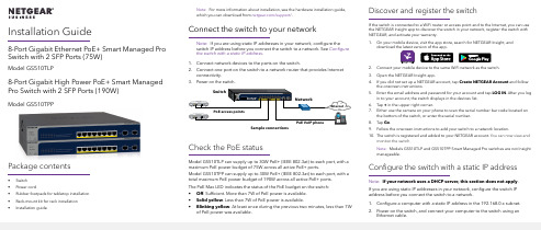
Installation Guide8-Port Gigabit Ethernet PoE+ Smart Managed Pro Switch with 2 SFP Ports (75W)Model GS510TLP8-Port Gigabit High Power PoE+ Smart Managed Pro Switch with 2 SFP Ports (190W)Model GS510TPPPackage contents• Switch• Power cord• Rubber footpads for tabletop installation• Rack-mount kit for rack installation• Installation guideNote: For more information about installation, see the hardware installation guide, which you can download from /support/.Connect the switch to your networkNote: If you are using static IP addresses in your network, configure theswitch IP address before you connect the switch to a network. See Configure the switch with a static IP address.1. Connect network devices to the ports on the switch.2. Connect one port on the switch to a network router that provides Internetconnectivity.Check the PoE statusModel GS510TLP can supply up to 30W PoE+ (IEEE 802.3at) to each port, with amaximum PoE power budget of 75W across all active PoE+ ports.Model GS510TPP can supply up to 30W PoE+ (IEEE 802.3at) to each port, with atotal maximum PoE power budget of 190W across all active PoE+ ports.The PoE Max LED indicates the status of the PoE budget on the switch:• Off. Sufficient. More than 7W of PoE power is available.• Solid yellow. Less than 7W of PoE power is available.• Blinking yellow. At least once during the previous two minutes, less than 7Wof PoE power was available.Discover and register the switchIf the switch is connected to a WiFi router or access point and to the Internet, you can usethe NETGEAR Insight app to discover the switch in your network, register the switch withNETGEAR, and activate your warranty.1. On your mobile device, visit the app store, search for NETGEAR Insight, anddownload the latest version of the app.2. Connect your mobile device to the same WiFi network as the switch.3. Open the NETGEAR Insight app.4. If you did not set up a NETGEAR account, tap Create NETGEAR Account and followthe onscreen instructions.5. Enter the email address and password for your account and tap LOG IN. After you login to your account, the switch displays in the devices list.6. Tap + in the upper right corner.7. Either use the camera on your phone to scan the serial number bar code located onthe bottom of the switch, or enter the serial number.8. Tap Go.9. Follow the onscreen instructions to add your switch to a network location.10. The switch is registered and added to your NETGEAR account. You can now view andmonitor the switch.Note: Models GS510TLP and GS510TPP Smart Managed Pro switches are not Insightmanageable.Configure the switch with a static IP addressNote: If your network uses a DHCP server, this section does not apply.If you are using static IP addresses in your network, configure the switch IPaddress before you connect the switch to a network.1. Configure a computer with a static IP address in the 192.168.0.x subnet.2. Power on the switch, and connect your computer to the switch using anEthernet cable.NETGEAR, Inc.350 East Plumeria DriveSan Jose, CA 95134, USANETGEAR INTERNATIONAL LTD Floor 1, Building 3University Technology Centre Curraheen Road, Cork, T12EF21, Ireland© NETGEAR, Inc., NETGEAR and the NETGEAR Logoare trademarks of NETGEAR, Inc. Any non‑NETGEARtrademarks are used for reference purposes only.SupportThank you for purchasing this NETGEAR product. You can visithttps:///support/ to register your product, get help, access the latest downloads and user manuals, and join our community. We recommend that you use only official NETGEAR support resources.Si ce produit est vendu au Canada, vous pouvez accéder à ce document en français canadien à https:///support/download/.(If this product is sold in Canada, you can access this document in Canadian French at https:///support/download/.)For regulatory compliance information including the EU Declaration of Conformity, visit https:///about/regulatory/.See the regulatory compliance document before connecting the power supply.Do not use this device outdoors. If you connect cables or devices that are outdoors to this device, see https:///000057103 for safety and warranty information.August 20193. Open a web browser and enter 192.168.0.239 in the address bar.(The default IP address of the switch is 192.168.0.239) A login page displays.4. Enter password for the password.The System Information page displays.5. Select System > Management > IP Configuration . Select the Static IPAddress radio button.6. Enter the static IP address, subnet mask, and default gateway IP address thatyou want to assign to the switch and click the Apply button.Your settings are saved.Configure the switchTo configure the switch either:• Use the local browser browser–based interface.• Install the NETGEAR Switch Discovery Tool on your Mac or a 64-bit Windows-based computer.•Install the Smart Control Center utility on your Windows-based computer.Access the local browser interface1. For initial configuration, open a web browser on a computer that is on thesame network and subnet as the switch and enter the switch’s IP address.If you are unsure how to determine the IP address of the switch, you can use the Smart Control Center utility.2. A login page displays. Enter password for the password.The System Information page displays.3. Configure the switch for your network.For information about switch configuration, see the user manual for your switch, which you can download from /support/.Other discovery and configuration methodsThe NETGEAR Switch Discovery Tool and the Smart Control Center utility let you discover the IP address and configure the switch. •NETGEAR Switch Discovery Tool . You can use a Mac or a 64-bit Windows-based computer on the same network as the switch. To download this tool, visit /support/product/netgear-switch-discovery-tool.aspx.•Smart Control Center utility . You can use a Windows-based computer on the same network as the switch. To download this utility, visit /support/product/SCC .Troubleshooting tipsHere are some tips for correcting simple problems that might occur.•Be sure to power on your computer and switch in the following sequence:a. Turn on the switch and wait about two minutes.b. Turn on the computer and connect it to the switch.•Make sure the Ethernet cables are plugged in.For each powered-on computer connected to the switch, the corresponding switch LAN port status LED is lit.•Make sure the network settings of the computer are correct.In most cases, computers should be configured to obtain an IP addressthrough DHCP . If your network uses static IP addresses, be sure that the switch and computer are configured with valid IP addresses. For more i nformation, see the user manual.。
烽火设备基础资料

780BNMU单盘硬件
面板指示灯含义
指示灯 ACT
UA/NUA NET SBUS MBUS
DCC指示灯
指示灯状态
备注
长亮但不闪烁表示 NMU盘未得到正确的配置 或时间;正常工作时,均 匀闪烁。
★ MBS1 MBUS1口通讯状态指示.闪动表示该口收到数据,本设备对外有6个MBUS1
口并联使用,可将其它功能模块(框、架)纳入到本设备进行管理
★ MBS2 MBUS2口通讯状态指示 闪动表示该口收到数据
★ DCCw 西DCC接收指示
闪动表示该口收到数据
★ DCCe 东DCC接收指示
闪动表示该口收到数据
6 6 611 3 3 322
EEEEEE 111111 ︱︱︱︱︱︱
666666 333333
123
456789
00 01 02 03 04 05 06 0 0 09 0 0 0 0 0 0F
11
78
ABCDE
风扇及分纤单元
OO
TTAAO 0
OO
25 25
U U U U 15 15
25 25
00 00
★ SBUS BCT应答指示 均匀闪动表示BCT与EMU通讯正常,不闪动表示
EMU未收到BCT应答,闪动频度不均匀表示可能有BCT通讯不好
★ NET F口数据指示灯 该灯以一定的频率闪动表示F口有数据收发
★ DCC0~3 从CPU串行口1~4指示灯 闪动表示该口收到数据
GF155-03BEMU单盘说明
❖ 可对某站点的光/电分支设备进行管理,;
晟矽微电子MC30P6250单片机用户手册说明书

SinoMCU 8位单片机MC30P6250用户手册V1.1本产品为广东晟矽微电子有限公司研制并销售,公司保留对产品在可靠性、功能和设计方面的改进作进一步目录1产品概要 (4)1.1产品特性 (4)1.2订购信息 (5)1.3引脚排列 (5)1.4端口说明 (6)2电气特性 (7)2.1极限参数 (7)2.2直流电气特性 (7)2.3交流电气特性 (8)2.4CMP特性参数 (9)3CPU及存储器 (10)3.1指令集 (10)3.2程序存储器 (12)3.3数据存储器 (12)3.4堆栈 (13)3.5控制寄存器 (13)3.6用户配置字 (15)4系统时钟 (16)4.1内部高频RC振荡器 (16)4.2内部低频RC振荡器 (17)4.3外部晶体振荡器 (17)4.4系统工作模式 (17)4.5低功耗模式 (18)5复位 (19)5.1复位条件 (19)5.2上电复位 (20)5.3外部复位 (20)5.4低电压复位 (20)5.5看门狗复位 (20)6I/O端口 (21)6.1通用I/O功能 (21)6.2内部上/下拉电阻 (21)6.3端口模式控制 (22)7定时器TIMER (23)7.1看门狗定时器WDT (23)7.2定时器T0 (24)7.3定时器T1 (26)8比较器CMP和电压检测EVD (31)8.1CMP概述 (31)8.2CMP相关寄存器 (32)9中断 (34)9.1外部中断 (34)9.2定时器中断 (34)9.3CMP中断 (34)9.4键盘中断 (35)9.5中断相关寄存器 (35)10特性曲线 (37)10.1I/O特性 (37)10.2功耗特性 (40)10.3模拟电路特性 (45)11封装尺寸 (49)11.1SOP8 (49)11.2DIP8 (49)11.3SOT23-6 (50)12修订记录 (51)1产品概要1.1产品特性⏹8位CPU内核✧精简指令集,5级深度硬件堆栈✧CPU为单时钟,仅在系统主时钟下运行✧系统主时钟下F CPU可配置为2/4分频⏹存储器✧1K×14位OTP型程序存储器✧50字节SRAM/REG型通用数据存储器,支持直接寻址、间接寻址等多种寻址方式⏹1组共6个I/O✧P1(P10~P15)✧P13为输入/开漏输出口,可复用为外部复位RST输入,编程时为高压VPP输入✧P15/P14可复用为外部时钟振荡器输入/输出✧所有端口均内置上拉电阻,P10~P12内置下拉电阻,均可单独使能✧除P13外其余端口均可选开漏或推挽输出✧所有端口均支持键盘中断唤醒功能,并可单独使能⏹系统时钟源✧内置高频RC振荡器(16MHz/8MHz/4MHz/2MHz/1MHz/455KHz),可用作系统主时钟源✧支持外接高频晶体振荡器(455KHz/4MHz~16MHz),可用作系统主时钟源✧内置低频RC振荡器(32KHz),可用作系统主时钟源、或系统低频时钟源✧支持外接低频晶体振荡器(32768Hz),可用作系统主时钟源、或系统低频时钟源⏹系统工作模式✧运行模式:CPU在系统主时钟下运行✧休眠模式:CPU停止运行,系统主时钟源停止工作⏹内部自振式看门狗计数器(WDT)✧与定时器T0共用预分频器✧溢出时间可配置:4.5ms/18ms/72ms/288ms(无预分频)✧工作模式可配置:开启WDT、关闭WDT,也可软件控制开启或关闭⏹2个定时器✧8位定时器T0,支持系统低频时钟,可实现外部计数功能,与WDT共用预分频器✧8位定时器T1,可实现外部计数、BUZ、4路共周期独立占空比的PWM(可组合成2对互反的带死区互补PWM)⏹1个模拟比较器CMP✧输入共模0 ~(VDD-1.4V),输出无回滞✧正端输入可选择外部输入电压、或内部参考电压V IR(0.5V)✧负端输入可选择外部输入电压、或外部输入电压/VDD的内部分压电压✧输出端电平可选择上升沿或下降沿触发中断,可从端口输出且支持输出取反✧可实现VDD或外部输入的电压检测(EVD)功能⏹中断✧外部中断(INT),键盘中断(P10~P15)✧ 定时器中断(T0~T1),CMP 中断⏹ 低电压复位LVR :1.8V/2.0V/2.3V/2.7V/3.0V ⏹ 工作电压✧ V LVR27 ~ 5.5V @ Fcpu = 0~8MHz ✧ V LVR20 ~ 5.5V @ Fcpu = 0~4MHz ✧ V LVR18 ~ 5.5V @ Fcpu = 0~1MHz ⏹ 封装形式:SOP8/DIP8/SOT23-61.2 订购信息产品名称 封装形式 备注 MC30P6250A0H SOP8 MC30P6250A0A DIP8 MC30P6250A0T SOT23-6 MC30P6250A1TSOT23-61.3 引脚排列MC30P6250A0H/A0AMC30P6250A0H/A0ASOP8/DIP812348765VDDGNDOSCI/EVN1/PWM1D/P15[SDO]/OSCO/EVN0/P14[VPP]/RST/CMPN/P13P11/PWM1B/[SDI]P12/TC0/BUZ1/PWM1A/CMPO/[SCK]P10/INT/TC1/PWM1C/EVN2/[SDO]MC30P6250A0TMC30P6250A0TSOT23-61[SDI]/PWM1B/P112GND3[SDO]/EVN0/P14654P12/TC0/BUZ1/PWM1A/CMPO/[SCK]VDDP13/CMPN/RST/[VPP]MC30P6250A1TMC30P6250A1TSOT23-61[VPP]/RST/CMPN/P132[SCK]/CMPO/PWM1A/BUZ1/TC0/P123VDD654P11/PWM1B/[SDI]P10/INT/TC1/PWM1C/EVN2/[SDO]GND1.4 端口说明端口名称 类型 功能说明VDD P 电源 GND P 地P10~P12 D GPIO (可选推挽/开漏输出),内部上/下拉 P14~P15 D GPIO (可选推挽/开漏输出),内部上拉 P13 D GPIO (开漏输出),内部上拉 INT DI 外部中断输入TC0~TC1 DI 定时器T0~T1的外部计数输入 PWM1A~PWM1DDO 定时器T1的4路PWM 输出 BUZ1 DO 定时器T1的BUZ 输出 CMPN AI CMP 负端外部输入EVN0 AI CMP 正端外部输入;CMP 电压检测外部输入通道 EVN1~EVN2 AI CMP 电压检测外部输入通道 CMPO DO CMP 输出OSCI ,OSCOA 外部时钟振荡器输入/输出 RST DI 外部复位输入SCK ,SDI ,SDOD 编程时钟/数据输入/数据输出接口 VPPP编程高压输入注:P-电源;D-数字输入输出,DI-数字输入,DO-数字输出;A-模拟输入输出,AI-模拟输入,AO-模拟输出。