基于无线传感器网络的co监测系统
基于无线传感器网络的环境监测与控制系统设计
基于无线传感器网络的环境监测与控制系统设计一、引言无线传感器网络(Wireless Sensor Network,WSN)是一种由大量分布式传感器节点组成的网络系统,用于监测和控制环境中的物理和化学参数。
WSN已经广泛应用于环境监测、农业、工业自动化等领域。
本文旨在设计一种基于无线传感器网络的环境监测与控制系统,通过对环境参数的实时监测和控制来提高资源利用效率、降低能源消耗,实现对环境的智能化管理。
二、系统架构设计2.1 传感器节点传感器节点是WSN中最基本的组成单元,负责采集环境参数并将数据传输给基站。
在本系统中,每个传感器节点由一个或多个传感器模块、一个微处理器和一个无线通信模块组成。
其中,传感器模块负责采集温度、湿度等环境参数,并将数据转换为数字信号;微处理器负责对采集到的数据进行处理和分析;无线通信模块则负责将处理后的数据发送给基站。
2.2 基站基站是WSN中负责接收并处理来自各个传感器节点数据的设备。
在本系统中,基站由一台高性能计算机和一个无线通信模块组成。
无线通信模块负责接收传感器节点发送的数据,并将数据传输给计算机进行处理。
计算机通过对接收到的数据进行分析和处理,得到环境参数的变化趋势,并根据需求制定相应的控制策略。
2.3 控制器控制器是根据基站分析得到的环境参数变化趋势,对环境进行控制的设备。
在本系统中,控制器由一个执行机构和一个控制算法组成。
执行机构负责根据控制算法给出的指令,对环境参数进行调节;控制算法则根据基站分析得到的数据和预设的目标值,通过数学模型计算出相应的调节策略。
三、系统工作流程3.1 环境参数采集传感器节点通过传感器模块采集环境中温度、湿度等参数,并将采集到的数据转换为数字信号。
3.2 数据传输传感器节点通过无线通信模块将采集到的数据发送给基站。
基站接收到来自各个传感器节点发送过来的数据,并将其存储在计算机中。
3.3 数据处理与分析基站上运行着一套完善的数据处理与分析算法,通过对接收到的数据进行分析,得到环境参数的变化趋势。
基于无线传感器网络的环境监测系统设计和实现

基于无线传感器网络的环境监测系统设计和实现随着现代社会的高速发展和城市化的不断推进,环境污染逐渐成为人们关注的热点问题。
为了有效地预防和治理环境污染,需要对环境进行实时监控和管理。
基于无线传感器网络的环境监测系统应运而生,成为环境监测领域的重要工具。
本文将介绍基于无线传感器网络的环境监测系统的设计和实现。
一、无线传感器网络简介无线传感器网络(Wireless Sensor Network,WSN)是一种利用无线通信技术构建的分布式、自组织、多传感器节点协作的网络系统。
WSN由大量的传感器节点、数据处理节点和控制节点组成,通过无线通信技术形成一个协同工作的整体。
每个传感器节点都具有一定的自主处理能力和通信能力,并能够自我组织形成网络。
传感器节点通常由微处理器、传感器、存储器和无线模块等构成。
二、环境监测系统的设计原理基于无线传感器网络的环境监测系统通常需要设计以下几个部分:1. 传感器网络部分传感器网络部分是整个系统的核心,主要由传感器节点和基站组成。
传感器节点负责采集环境参数,如温度、湿度、风速、气压等。
基站则负责接收、处理和传输数据。
2. 数据处理部分数据处理部分主要负责对传感器节点采集到的数据进行处理、分析、存储等操作。
这个部分需要使用一些数据处理技术和算法,如数据压缩、数据挖掘和机器学习等。
3. 数据显示部分数据显示部分主要是将处理后的数据以可视化的形式呈现给用户。
这个部分需要使用一些可视化工具和技术,如Web技术、图表控件、地图等。
三、基于无线传感器网络的环境监测系统的实现方法在实现基于无线传感器网络的环境监测系统时,需要考虑以下几个方面:1. 传感器节点的选择和部署选择合适的传感器节点对于提高系统的性能和精度至关重要。
传感器节点的部署也需要经过仔细的规划和布局。
2. 通信协议的选择需要选择合适的通信协议,如ZigBee、WiFi、LoRa等。
通信协议的选择将直接影响到系统的能耗、通信效率和可靠性。
基于无线传感器网络的智能智能农业监测系统设计

基于无线传感器网络的智能智能农业监测系统设计智能农业监测系统设计——为农业生产带来高效与便利随着科技的不断发展,农业生产也逐渐趋向智能化。
在智能农业监测系统的设计中,无线传感器网络被广泛应用,为农民提供了实时、准确的农业监测数据,促进农业生产的可持续发展。
一、系统架构设计基于无线传感器网络的智能农业监测系统主要由传感器节点、传感器数据采集与处理模块、数据传输与通信模块以及数据分析与管理模块构成。
1. 传感器节点:传感器节点分布在田地、温室和畜牧场等农业环境中,用于采集和监测环境中的温度、湿度、光照、土壤湿度、气体浓度等关键参数。
传感器节点具备低功耗、高灵敏度、远距离通信等特点,能够长时间运行并在数据达到预设阈值时及时发送数据。
2. 传感器数据采集与处理模块:该模块负责对传感器节点采集到的数据进行处理和分析。
传感器数据采集与处理模块将采集到的数据进行滤波、校正和采样等处理,保证数据的精确性和可靠性。
3. 数据传输与通信模块:数据传输与通信模块通过无线网络将采集到的数据传输到数据分析与管理模块。
当前,常用的数据传输与通信技术包括Wi-Fi、LoRa、NB-IoT等,根据实际情况选择合适的数据传输方式。
4. 数据分析与管理模块:数据分析与管理模块负责接收、存储和分析传感器节点采集到的数据。
通过数据分析和算法模型,农业专家和农户可以及时了解农作物生长情况、土壤营养状况、病虫害预警等信息,以便采取针对性的措施。
二、系统功能设计基于无线传感器网络的智能农业监测系统设计具备多种功能,以满足农业生产的需求:1. 实时监测和预警:系统能够实时监测农作物生长环境和土壤状况,并根据预设的阈值进行预警。
例如,当土壤湿度过低或有害气体浓度异常时,系统将自动发送通知给农户或农技人员,以便及时采取措施。
2. 精确灌溉与施肥:根据不同作物的需水和需肥量,系统通过分析传感器节点采集到的数据,精确控制灌溉和施肥设备,实现水、肥的科学、高效利用,减少资源浪费。
高铁交通中的列车基于无线传感器网络的监控系统

高铁交通中的列车基于无线传感器网络的监控系统随着科技的不断发展,无线传感器网络已经成为高铁交通中列车监控系统的重要组成部分。
通过无线传感器网络,可以对列车进行实时监控,实现对列车运行状态、乘客安全等方面的监测与管理。
在高铁交通中,列车基于无线传感器网络的监控系统发挥着重要的作用,能够提高列车的运行安全性和运行效率。
一、无线传感器网络在列车监控系统中的应用无线传感器网络由一组分布在列车中的无线传感器组成,通过无线通信技术与中央控制系统实现信息的实时交互。
传感器能够采集列车运行过程中的多种信息,如列车位置、速度、温度、湿度等。
通过无线传感器网络将这些信息传输到中央控制系统,可以实现对列车的远程监控。
1. 监测列车位置和速度通过无线传感器网络,可以实时获取列车的位置和速度信息,并将其传输到监控中心。
这样,监控中心就能够实时了解各列车的运行状态,包括列车是否按时运行、列车是否在规定的速度范围内等。
一旦发现异常情况,监控中心可以及时采取相应的措施,确保列车的安全运行。
2. 监测列车温度和湿度列车内部的温度和湿度对乘客的舒适度和健康状况有很大影响。
通过在列车中布置传感器,可以实时监测列车的温度和湿度,并将数据传输到监控中心。
监控中心可以根据实时数据调整列车的温湿度控制系统,以确保乘客的舒适度和健康状况。
3. 监测列车内部环境除了温度和湿度外,列车的内部环境还包括气体浓度、噪声等。
通过无线传感器网络,可以实时监测列车内部环境的各项指标,并将其传输到监控中心。
监控中心可以根据实时数据进行环境调整,提高列车内部环境的质量,并确保乘客的舒适度和健康状况。
4. 监测列车结构和设备状态高铁列车的结构和设备的状态对列车的运行安全性至关重要。
通过无线传感器网络,可以监测列车结构和设备的运行状态,并将数据传输到监控中心。
监控中心可以根据实时数据进行维修和保养计划,保证列车的运营安全性和可靠性。
二、列车基于无线传感器网络的监控系统的优势1. 实时性强无线传感器网络能够实时采集和传输列车的各类信息,监控中心可以实时了解列车的运行状态,及时做出相应的调整和处理。
无线传感器网络在环境监测系统中应用论文

无线传感器网络在环境监测系统中的应用【摘要】本文介绍了在环境监测系统中应用无线传感器网络技术的几点优势,分析了基于无线传感器网络技术的环境监测系统的体系结构,给出了三个典型应用领域中该系统的创新性构建方案,并对该类系统中的几种关键技术进行了研究,最后对无线传感器网络技术的应用前景进行了展望。
【关键词】无线传感器网络 zigbee ieee 802.15.4 能源管理数据融合近年来,随着无线传感器网络技术的迅猛发展,以及人们对于环境保护和环境监督提出的更高要求,越来越多的企业和机构都致力于在环境监测系统中应用无线传感器网络技术的研究。
通过在监测区域内布署大量的廉价微型传感器节点,经由无线通信方式形成一个多跳的网络系统,从而实现网络覆盖区域内感知对象的信息的采集量化、处理融合和传输应用。
无线传感器网络技术是应用性非常强的技术,它在当前我国环境监测系统中的应用潜力是巨大的。
一、无线传感器网络和zigbee无线传感器网络(wireless sensor network,wsn)是由部署在监测区域内大量的廉价微型传感器结点通过无线通信技术自组织构成的网络系统。
人们可以通过传感器网络直接感知客观世界,在工业自动化领域,利用无线传感器网络技术实现远程检测、控制,从而极大地扩展现有网络的功能。
传感器网络、塑料电子学和仿生人体器官又被称为全球未来的三大高科技产业。
zigbee是一种新兴的短距离、低功耗、低数据速率、低成本、低复杂度的无线网络技术。
二、ieee 802.15.4/zigbee协议1、ieee 802.15.4标准ieee标准化协会针对无线传感器网络需要低功耗短距离的无线通信技术为低速无线个人区域网络(lr—wpan)制定了ieee 802.15.4标准。
该标准把低能量消耗、低速率传输、低成本作为重点目标,旨在为个人或者家庭范围内不同设备之间低速互连提供统一标准。
同时zigbee联盟也开始推出与之相配套的网络层及应用层的协议,目的是为了给传感器网络和控制系统推出一个标准的解决方案。
《基于无线传感网的环境监测系统的研究与实现》范文

《基于无线传感网的环境监测系统的研究与实现》篇一一、引言随着科技的不断进步,环境监测已经成为了一个重要的研究领域。
为了实现环境监测的高效性、实时性和准确性,无线传感网技术被广泛应用于此领域。
本文旨在研究并实现一个基于无线传感网的环境监测系统,通过分析系统需求、设计、实现及测试,验证了该系统的可行性和有效性。
二、系统需求分析环境监测系统的主要目标是实时收集并传输环境数据,以便于分析和管理。
基于无线传感网的特性,我们提出了一套完整的需求分析:1. 数据收集:系统应能够实时收集包括空气质量、水质、土壤质量、气象条件等在内的环境数据。
2. 传输网络:使用无线传感网络技术,将收集到的数据传输至中心服务器。
3. 数据处理:中心服务器应能对接收到的数据进行处理和分析,生成环境质量报告。
4. 用户界面:提供一个友好的用户界面,使用户能够方便地查看和分析环境数据。
三、系统设计基于上述需求分析,我们设计了以下系统架构:1. 硬件设计:采用无线传感器节点进行环境数据收集。
每个节点包括传感器、微处理器和无线通信模块。
2. 网络设计:采用无线传感网技术,将各个传感器节点与中心服务器连接起来,形成一个自组织的网络。
3. 软件设计:开发一套数据处理软件,用于接收、处理和存储环境数据,并生成环境质量报告。
同时,开发一个用户界面,使用户能够方便地查看和分析环境数据。
四、系统实现在系统实现阶段,我们主要完成了以下工作:1. 硬件实现:根据硬件设计,制作了无线传感器节点,并将其部署在需要监测的环境中。
2. 网络实现:利用无线传感网技术,将各个传感器节点与中心服务器连接起来,形成一个稳定、可靠的传输网络。
3. 软件实现:开发了数据处理软件和用户界面。
数据处理软件能够实时接收、处理和存储环境数据,并生成环境质量报告。
用户界面则提供了一个友好的界面,使用户能够方便地查看和分析环境数据。
五、系统测试与性能评估为了验证系统的可行性和有效性,我们对系统进行了测试和性能评估。
物联网中基于无线传感器的环境监测系统设计

物联网中基于无线传感器的环境监测系统设计当我们谈到物联网时,我们往往会想到各种智能设备之间的互联互通,但实际上物联网的应用远不止于此。
其中一个重要的应用领域就是环境监测系统。
基于无线传感器的环境监测系统设计,是将传感器节点与通信技术相结合,实现对环境参数进行实时监测和数据传输的一种新型系统。
在本文中,我们将探讨物联网中基于无线传感器的环境监测系统设计的原理、技术和应用。
无线传感器网络(WSN)是一种由大量分布在监测区域内的传感器节点构成的网络,用来实时监测和采集环境数据。
每个传感器节点都配备有传感器、处理器、通信模块和电源模块,可以独立工作,并通过无线通信协议与其他节点进行数据传输。
传感器节点通过构建自组织的网络拓扑结构,实现对环境参数的协同监测和数据传输,从而为环境监测系统提供了实时、准确的数据支持。
在无线传感器网络中,节点之间的通信是至关重要的。
通信技术的选择不仅影响了系统的传输速率和可靠性,还直接关系到系统的能耗和网络拓扑结构的设计。
目前常用的传感器节点通信技术包括ZigBee、Bluetooth、LoRa等。
ZigBee通信技术具有低功耗、低成本、低速率、短距离等特点,适合用于小范围内的传感器节点之间的数据传输;Bluetooth通信技术适用于中距离的传输,速率较高,但功耗也相对较高;LoRa通信技术在长距离通信方面有优势,但速率相对较低。
根据环境监测系统的具体需求,可以选择合适的通信技术,实现节点之间的数据传输和协同工作。
除了传感器节点之间的通信,环境监测系统的设计还需要考虑到数据的采集、处理和传输。
传感器节点通过传感器实时采集环境数据,并通过处理器对数据进行处理,提取出有用的信息。
随着物联网技术的不断发展,传感器节点的处理器性能和存储容量逐渐增加,可以实现更复杂的数据处理和分析算法。
通过数据压缩、数据挖掘和数据融合等技术手段,可以有效提高数据的利用率和系统的性能。
数据传输是环境监测系统中的一个重要环节。
【CN209745914U】一种基于无线、有线传输的CO实时监测管理系统【专利】
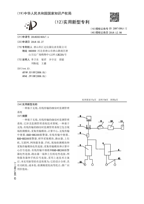
(19)中华人民共和国国家知识产权局(12)实用新型专利(10)授权公告号 (45)授权公告日 (21)申请号 201920246317.1(22)申请日 2019.02.27(73)专利权人 唐山科汇达仪器仪表有限公司地址 063000 河北省唐山市唐山路南区唐山万达广场购物中心2单元B2201号(72)发明人 李卫东 郁君 齐守宏 邵毅 刘振起 王鑫 (51)Int.Cl.G01N 33/00(2006.01)H04L 29/08(2006.01)(54)实用新型名称一种基于无线、有线传输的CO实时监测管理系统(57)摘要一种基于无线、有线传输的CO实时监测管理系统,它涉及监测管理系统技术领域。
一种基于无线、有线传输的CO实时监测管理系统它包含现场检测模块、采集传输模块、计算中心、无线传输中继箱、KHD -BK200报警器、有线传输中继箱、KHD -BD200报警器、研华采集模块、路由器、上位机、互联网、网络服务器、手机,现场检测模块和采集传输模块电性连接,采集传输模块和计算中心信号连接,有线传输中继箱和KHD -BK200报警器电性连接,路由器一端和上位机电性连接,网络服务器和手机信号连接。
采用上述技术方案后,本实用新型的有益效果为:它的设计合理,具有功耗低、成本低、检测精度较高等优点,推广应用价值高。
权利要求书1页 说明书3页 附图1页CN 209745914 U 2019.12.06C N 209745914U权 利 要 求 书1/1页CN 209745914 U1.一种基于无线、有线传输的CO实时监测管理系统,其特征在于:它包含现场检测模块(1)、采集传输模块(2)、计算中心(3)、无线传输中继箱(4)、KHD-BK200报警器(41)、有线传输中继箱(5)、KHD-BD200报警器(51)、研华采集模块(6)、路由器(7)、上位机(8)、互联网(9)、网络服务器(10)、手机(11),现场检测模块(1)和采集传输模块(2)电性连接,采集传输模块(2)和计算中心(3)信号连接,无线传输中继箱(4)一侧连接有线传输中继箱(5),无线传输中继箱(4)和KHD-BD200报警器(41)电性连接,有线传输中继箱(5)和KHD-BK200报警器(51)电性连接,研华采集模块(6)与无线传输中继箱(4)和有线传输中继箱(5)电性连接,研华采集模块(6)和路由器(7)电性连接,路由器(7)一端和上位机(8)电性连接,路由器(7)和互联网(9)通讯连接,网络服务器(10)和手机(11)信号连接。
《基于无线传感网的环境监测系统的研究与实现》范文

《基于无线传感网的环境监测系统的研究与实现》篇一一、引言随着科技的进步与环保意识的增强,环境监测已经成为保护环境与自然资源的重要手段。
基于无线传感网络(Wireless Sensor Network, WSN)的环境监测系统能够有效地解决复杂环境下信息获取和传输的问题。
本文将对基于无线传感网的环境监测系统的研究与实现进行详细的探讨,并针对具体的技术难点进行剖析和解决方法的分析。
二、系统架构及技术难点2.1 系统架构基于无线传感网的环境监测系统主要由传感器节点、网关节点、数据中心等部分组成。
传感器节点负责环境信息的采集和传输,网关节点负责数据的汇聚和传输至数据中心,数据中心负责数据的处理、存储和分析等任务。
2.2 技术难点(1)数据采集:如何在复杂的自然环境中获取准确的实时数据是一个重要问题。
此外,还需要考虑数据传输的可靠性和稳定性。
(2)能源效率:无线传感器网络通常使用电池供电,因此,如何在长时间内保证网络的正常运转是另一个重要的问题。
(3)网络安全:在传输敏感的监测数据时,如何确保数据的完整性和保密性也是不容忽视的问题。
三、研究与实现3.1 传感器节点的设计与实现传感器节点是环境监测系统的关键部分,负责数据的采集和传输。
设计时需要考虑到传感器节点的尺寸、功耗、成本等因素。
此外,还需要根据具体的监测环境选择合适的传感器类型和参数。
在实现过程中,需要使用微处理器和无线通信模块等硬件设备,以及相应的软件算法进行数据处理和传输。
3.2 网关节点的设计与实现网关节点是连接传感器节点和数据中心的关键部分,负责数据的汇聚和传输。
在设计和实现过程中,需要考虑到数据的处理能力、存储能力和传输速度等因素。
此外,还需要考虑如何对数据进行加密和验证,以确保数据的安全性和完整性。
3.3 数据中心的设计与实现数据中心是环境监测系统的核心部分,负责数据的处理、存储和分析等任务。
在设计和实现过程中,需要考虑到数据存储的容量、处理速度和安全性等因素。
基于无线传感器网络的智能家居监控系统实现

基于无线传感器网络的智能家居监控系统实现智能家居监控系统是指通过无线传感器网络技术实现对家庭环境、设备及安全的全面监控和控制的系统。
它通过采集家庭各个区域的环境数据,并将数据传输到中央处理器进行分析和决策,从而实现远程监控和控制家庭设备的智能化管理。
本文将重点介绍基于无线传感器网络的智能家居监控系统的实现原理及其应用。
一、无线传感器网络简介无线传感器网络是由大量分布在网络范围内的无线传感器节点组成的自组织网络系统。
每个传感器节点都具备数据采集、处理和通信功能。
传感器节点通过无线通信将采集到的数据传输至基站或中央处理器进行处理和管理。
无线传感器网络具有节点数量多、部署灵活、无线通信、低成本等特点,广泛应用于智能家居、工业自动化、环境监测等领域。
二、智能家居监控系统实现原理1. 环境监测智能家居监控系统通过无线传感器节点实时采集家庭各个区域的环境数据,包括温度、湿度、光照强度、空气质量等。
传感器节点将采集到的数据通过无线通信传输至中央处理器进行分析和存储。
用户可以通过手机等智能终端随时了解家庭各区域的环境情况,及时做出相应的调整和控制。
2. 安全监控智能家居监控系统还可以通过无线传感器节点实现对家庭安全的监控。
例如,通过布置入侵探测器、烟雾探测器、门窗磁感应器等传感器节点,实时监测家庭的安全情况。
当发生异常事件时,系统会立即向用户发送警报信息,同时可以实现远程视频监控,用户可以通过智能终端观看家庭实时画面,确保家庭安全。
3. 设备控制智能家居监控系统可以通过无线传感器网络实现对家庭设备的远程控制。
例如,通过智能插座传感器节点实现对家电设备的开关控制、定时控制,通过智能灯泡传感器节点实现对灯光的远程调节,通过智能门锁传感器节点实现对门锁的远程开关等。
用户可以通过手机等智能终端随时随地控制家庭设备,提高生活的便利性和舒适度。
三、智能家居监控系统的应用举例1. 环境智能化管理智能家居监控系统可以实时监测各个区域的温度、湿度、光照强度等环境因素,并根据用户的需求自动调节设备,提供舒适的居住环境。
基于无线传感网络的环境监测系统

基于无线传感网络的环境监测系统摘要:无线传感器网络是目前环境监测领域研究的热点技术。
结合ZigBee和无线传感网络设计了集多种功能于一体的完整环境监测系统。
在本系统中,节点选用CC2530芯片作为zigbee通信模块,网关采用GPRS作为系统与3G网络的通信模式。
系统实现了采集温度、湿度、光线亮度等环境信息,并进行了相应处理,设计了网关数据处理软件算法。
系统具体的工作方式为:传感器节点对室内的环境信息进行采集并将数据以ZigBee无线自组网方式发送到无线传感网络的控制中心网关,网关负责将传感器数据处理后上传到云服务器;用户能够通过手机APP和网页查看,对于重要的警告信息网关会发短信到用户的手机,而服务器端会发邮件或微博提醒用户。
经过测试和使用,本系统运行可靠,能准确获取环境数据,网关和服务器端数据能够实时更新,环境参数能实现自动调节与校准。
关键词:环境监测;无线传感网络;ZigBee;GPRS1 相关工作本文研究目的是利用ZigBee 技术结合 WSN 设计安全高效的、个性化的环境监测系统。
许多本领域学者已经利用WSN设计了一些环境监测系统,代表性的成果有:雷旭等利用无线传感器网络设计了隧道环境信息监测系统。
系统以STM32 微控制器为核心设计了低功耗网络节点与网络汇聚节点设计了B/S 模式访问的监控中心软件;梅海彬等提出了一种基于Arduino开放平台与XBee Pro增强通信距离的无线传感器网络,对近海环境进行了实时监测;另外,针对农田土壤参数(诸如温湿度等)的精确采集系统设计上,很多学者研究了土壤WSN 精确化应用系统与实现的关键技术。
诸如此类,这些都是典型的WSN环境监测系统与关键技术研究的文献成果。
概括这些目前WSN环境监测领域文献共性特点,大多是针对农业、海洋等某一领域设计的应用系统,缺乏共性通用的系统平台设计思想;另外由于缺乏目前云计算、Android等最先进的新技术植入,缺乏先进与人性化设计理念。
基于无线传感器网络的环境监测系统

基于无线传感器网络的环境监测系统无线传感器网络(Wireless Sensor Networks,WSNs)是一种利用无线通信技术和分散式传感器节点构成的自组织网络。
它通过无线传感器节点之间的协作,实时采集、处理和传输环境信息,具有广泛的应用前景。
基于无线传感器网络的环境监测系统可以对环境参数进行实时监测和数据采集,用于环境保护、资源管理、灾害预警等领域。
一、无线传感器网络的工作原理无线传感器网络由大量的无线传感器节点组成,这些节点通常由微处理器、传感器、无线通信模块和电源组成。
它们通过无线通信创建一个自组织、分布式的网络,在监测区域内部署形成感知层。
传感器节点通过感知环境参数(如温度、湿度、光照强度等)并将数据通过网络传输给基站,形成一个数据收集层。
基站作为数据的汇集和处理中心,负责数据的存储、处理和分析,同时可以与其他网络进行连接,如互联网,形成一个应用层。
在无线传感器网络中,传感器节点通常由两种方式工作:协同式和分布式。
在协同式工作模式下,节点之间通过协作来完成共同的任务,例如数据的传输和处理。
而在分布式工作模式下,节点独立地执行任务,节点之间不会进行通信。
这两种工作模式的选择取决于具体的应用场景和需求。
无线传感器网络自组织的特点使得它具有灵活性、可扩展性和自适应性。
传感器节点可以动态地加入或离开网络,使得网络能够自动适应环境的变化。
此外,无线传感器节点通常采用低功耗设计,以延长其工作寿命。
二、环境监测系统的设计与实现基于无线传感器网络的环境监测系统的设计和实现可以分为硬件部分和软件部分。
硬件部分主要包括传感器节点的选择和部署、数据采集和传输设备等。
在选择传感器节点时,需要根据具体的监测需求选择适合的传感器类型,例如温度传感器、湿度传感器、光照传感器等。
传感器节点的部署需要考虑监测区域的大小和形状,以及节点之间的通信距离和信号强度。
数据采集和传输设备负责节点之间的数据传输和接收,如无线通信模块和基站设备。
基于ZigBee无线传感器网络的环境质量监测系统设计

无线互联科技Wireless Internet Technology 第13期2019年7月No. 13July, 2019基TZigBee 无线传感器网络的环境质量监测系统设计马爱霞,徐音(郑州工商学院工学院,河南郑州 450014)摘 要:以CC2530模块为核心构建无线传感网络,将采集的粉尘、温湿度、光照等环境数据传输至远程监测中心,通过上位 机软件读取与储存环境数据,实现环境参数远程监测。
文章根据系统的方案,设计其硬件电路功能,并设计了终端传感器节 点、中间协调器节点以及监控中心的软件流程。
关键词:温湿度;光照;ZigBee ;无线传感网络随着人们生活水平的日益提高及科技技术的进步,环境 问题越来越受到重视,人们日常关注空气质量如同每天关注 天气预报一样频繁。
传统的环境监测技术主要是通采用人 工的方式,使用测量温湿度等指数的仪器检测环境质量参 数,人力、财力得到大量的消耗,并且在一些环境比较恶劣 的区域,使用人工方式很难实时监测,以上弊端都是传统监 测方法存在的。
随着互联网技术和无线传输技术的发展,这 些技术慢慢被投入到环境监测系统中来。
环境检测技术主 要运用的3种技术:传感器技术、通信技术、计算机技术。
传 感器完成检测信息的采集,通信技术完成信息传输,计算机 技术实现数据的处理。
无线传感器网络是由许多微小传感器节点构成的,微小 传感器负责系统数据的采集,各节点之间进行通信。
微小传 感器以多跳无线通信方式构成自组织的网络系统。
因其具有 可靠、灵活、准确等优点,同时,部件造价低廉、部署和维护 简单,近年来普及应用得非常快。
现在在智能家居、环境监 测、智能交通等领域得到了广泛应用。
1系统总体方案的设计本文是基于ZigBee 无线传感器技术的环境数据釆集和 控制系统"。
该系统由监测点、中心控制节点、通用分组无线 服务(General Packet Radio Service, GPRS )网络和上位机 监控中心组成。
基于无线传感器网络的智能环境监控与管理系统设计
基于无线传感器网络的智能环境监控与管理系统设计智能环境监控与管理系统是一种利用无线传感器网络技术进行环境监测和管理的新型系统。
它能够检测环境参数,并根据实时数据进行智能控制和管理,从而提高环境质量和能源效率。
本文将介绍基于无线传感器网络的智能环境监控与管理系统的设计原理和关键技术。
一、系统设计原理智能环境监控与管理系统的设计原理基于无线传感器网络技术。
传感器是系统的核心组成部分,通过感知环境,采集环境参数数据,并将数据通过无线通信传输到中心服务器。
中心服务器通过对接收到的数据进行分析和处理,实现环境的监测和管理。
系统的设计理念是实现智能化的环境监测和管理。
通过对环境参数的实时采集和数据分析,系统能够自动调节环境设备的工作状态,以提高能源效率和环境质量。
同时,系统还提供了可视化界面,用户可以通过界面实时监测环境参数并进行远程控制。
二、关键技术1. 无线传感器网络:系统采用无线传感器网络技术进行数据的采集和传输。
传感器节点通过无线通信与中心服务器进行数据交互,实现实时监测和数据传输的功能。
2. 传感器节点设计:传感器节点是系统的基本单元,它负责环境参数的采集和数据传输。
传感器节点设计需要考虑传感器的选择和布局、传感器节点的功耗控制和通信协议的选取等因素。
3. 数据分析与处理:系统中的中心服务器负责接收传感器节点发送的数据,并进行数据分析和处理。
服务器可以根据数据的情况进行智能调度和控制,实现环境的优化和能源的管理。
4. 可视化界面:系统提供了可视化的界面,用户可以通过界面实时监测环境参数、查看历史数据和进行远程控制。
界面设计需要考虑用户友好性和操作便捷性,以提升用户体验。
三、系统应用场景基于无线传感器网络的智能环境监控与管理系统在众多领域具有广泛的应用前景,其中几个主要的应用场景如下:1. 家居环境监控:系统可以监测室内温度、湿度、光照等参数,并自动调节空调、加湿器、灯光等设备,提供舒适的居住环境。
基于无线网络的环境监测系统设计与实现

基于无线网络的环境监测系统设计与实现随着科技的不断发展,环境监测成为了保护自然资源和人类健康的重要手段之一。
而基于无线网络的环境监测系统可以提供实时、准确的数据,帮助我们更好地了解和管理环境。
本文将探讨基于无线网络的环境监测系统的设计与实现,并介绍实现该系统所需的关键技术。
一、系统设计1. 系统架构基于无线网络的环境监测系统可以分为三个主要部分:传感器节点、无线网络和数据处理中心。
传感器节点负责收集环境数据,无线网络用于传输数据,而数据处理中心则负责对数据进行分析和处理。
2. 传感器节点设计传感器节点是系统的基本组成部分,它负责收集环境数据并将其发送给无线网络。
传感器节点应具备以下特点:(1)高精度:传感器节点应具备高度精准的测量能力,确保数据的准确性和可靠性。
(2)低功耗:为了实现长时间的运行,传感器节点应具备低功耗的设计,例如采用低功耗传感器和定时激活模式。
(3)多功能:传感器节点应能够同时监测多种环境参数,例如温度、湿度、光照等,以满足多样化的监测需求。
3. 无线网络设计无线网络用于传输传感器节点收集的环境数据至数据处理中心。
无线网络设计应具备以下特点:(1)稳定性:无线网络需要具备稳定的连接性,能够确保数据的及时传输和接收。
(2)扩展性:无线网络应具备较大的扩展性,能够支持多个传感器节点的同时连接。
(3)安全性:由于环境数据可能涉及用户隐私等敏感信息,无线网络应具备一定的安全性保护机制,例如数据加密和身份验证等。
4. 数据处理中心设计数据处理中心负责接收、分析和处理传感器节点发送的数据。
数据处理中心应具备以下特点:(1)实时性:数据处理中心应能够实时接收和处理数据,以及时发现异常情况并采取相应的措施。
(2)可视化:为了方便用户理解和利用环境数据,数据处理中心应该将数据以图表、曲线等形式进行展示,提供直观的分析结果。
(3)大数据处理能力:随着传感器节点数量和数据量的不断增加,数据处理中心需要具备一定的大数据处理能力,以应对日益增长的数据需求。
基于无线传感网络的环境监测系统
基于无线传感网络的环境监测系统摘要:当今环境污染问题已经严重制约了全球经济的发展和人类的健康。
加强环境监测,建立环保系统意义重大。
基于 ZigBee 双向无线通讯技术的环境在线监测系统,系统 ZigBee 的通信模块选用的芯片型号为 CC2530,系统网关的通信模式选用 GPRS模式,并利用数据分析模型对采集的数据进行了在线实时处理.经测试,设计环境实时采集监测系统能够稳定运行,能够实时获取数据并通过系统的网管在系统的服务器端实时更新,实现环境参数的实时监视。
关键词:ZigBee;无线传感网络;传感器随着经济和科技的发展,农业种植也有了长足的发展,从之前的小面积种植演变为了如今的大规模,为了提高生产效率,减少劳动力,必须引进先进的技术配合人工劳作进行种植。
传统的环境监测系统布线成本高,抗干扰性差,增加新监测点时必须改变物理线路,工序复杂,维护难度大。
当今环境污染问题已经严重制约了全球经济的发展和人类的健康。
每年因环境问题造成全球的经济损失达数千亿美元,酸雨造成了大量植物的坏死、污水的排放造成了人员伤亡及海水负营养化、许多岛国因温室效应造成的海平面上涨而面临着消失的危险。
增强环保意识,保护环境势在必行。
一、无线传感网络的环境监测系统技术特点1、多传感器数据融合技术。
每个节点采集到两种数据,是某一段区域的数据。
因为传感器采集到的数据大部分是静态数据,对于环境感知而言,动态数据才是最重要的。
这就要求节点自身能对先前采集到的数据进行过滤筛选,分离出有用的数据再传输给相邻的网关节点。
主机进行决策需要融合传感器节点的数据。
2、数据发送模式。
每个节点都有要具备接收和发射功能,实现数据的传输通信。
因为实际环境复杂,多数情况时比较恶劣的,要保证稳定可靠地无线收发数据,需要对天线、发射功率、灵敏度、收发距离设计。
多种数据发送模式的配合使用。
数据异常时的实时跟踪发送、数据稳定时的定时发送、工作人员发指令进行查询时的数据及时发送,不仅能使处理器得到休眠,降低了功耗,提高了使用寿命,还有效避免了大量无用数据的产生,有效提高了处理器的运行速度。
基于无线传感器网络的智能家居监控系统设计

基于无线传感器网络的智能家居监控系统设计智能家居监控系统是利用无线传感器网络技术为用户提供全方位的家庭安全保障和生活便利的系统。
本文将从系统设计、传感器选择、场景应用和优势等方面对基于无线传感器网络的智能家居监控系统进行详细阐述。
一、系统设计基于无线传感器网络的智能家居监控系统设计包括传感器节点、数据传输和数据处理三个主要组成部分。
1. 传感器节点:传感器节点是系统的核心组成部分,用于感知和采集家庭环境中的数据。
常见的传感器包括温湿度传感器、烟雾传感器、门窗磁传感器、人体红外传感器等。
这些传感器将感知到的数据通过无线方式传输给数据处理中心。
2. 数据传输:传感器节点采集到的数据通过无线通信方式传输到数据处理中心。
无线传感器网络可以采用Wi-Fi、蓝牙或者ZigBee等通信协议进行数据传输,保证数据的及时性和稳定性。
3. 数据处理:数据处理中心接收到传感器节点发送的数据后,通过数据处理算法进行分析和处理。
处理后的数据可以用于及时报警、家居设备控制或者生成智能家居的各类统计信息。
二、传感器选择为了保证智能家居监控系统的效果,需要合理地选择传感器。
以下介绍几种常见的传感器及其应用。
1. 温湿度传感器:温湿度传感器用于监测家庭环境的温度和湿度变化。
通过实时监测温湿度数据,可以及时调节空调和加湿器等设备,提升家庭生活的舒适度。
2. 烟雾传感器:烟雾传感器可用于检测家庭中的火灾情况。
一旦传感器检测到烟雾,系统会及时发出警报并向用户发送报警信息,为用户提供火灾的第一时间预警。
3. 门窗磁传感器:门窗磁传感器可以用于监测家庭门窗的开闭状态。
如果传感器检测到门窗被非法打开,系统将触发报警并通知用户,提高家庭的安全性。
4. 人体红外传感器:人体红外传感器能够检测到家庭中是否有人活动。
通过监测人体红外信号,系统可以自动控制照明、空调和安防设备等,实现节能和智能化。
三、场景应用基于无线传感器网络的智能家居监控系统在各个场景中都有广泛的应用。
基于无线传感器网络的环境监测系统的设计
第8期 2009年8月工矿自动化Industry and Mine AutomationNo.8 Aug.2009 文章编号:1671-251X (2009)08-0119-04基于无线传感器网络的环境监测系统的设计毛会琼1, 陈世海1, 范建国2, 刘世奎2, 牛光东2(1.中国矿业大学信电学院,江苏徐州 221008;2.新汶矿业集团,山东新汶 271219) 摘要:文章提出了一种基于无线传感器网络的企业环境监测系统的设计方案,详细阐述了环境监测系统的体系结构以及无线传感器网络节点的硬件设计和软件功能的实现方法。
该系统采用低功耗设计,运行稳定、精度高,可实现对企业环境在无人值守下的远程实时监测。
关键词:环境监测;无线传感器网络;节点;低功耗;无人值守 中图分类号:X 84;TP212.6 文献标识码:BDesign of Environment Monitoring System Based on Wireless Sensor NetworksMAO Hui 2qiong 1, C H EN Shi 2hai 1, FAN Jian 2guo 2, L IU Shi 2kui 2, N IU Guang 2dong 2(1.School of Information and Electrical Engineering of CUM T.,Xuzhou 221008,China.2.Xinwen Mining Indust ry Group ,Xinwen 271219,China ) Abstract :The paper p ut forward a design scheme of enterp rise environment monitoring system based on wireless sensor networks ,and expounded t he system architect ure of environment monitoring system ,hardware design ,and implementation met hod of software f unction of wireless sensor networks nodes.The system applies low power consumption and has stable running and high precision ,which can realize remote real 2time monitoring for unattended enterp rise 2oriented environment.K ey w ords :environment monitoring ,wireless sensor networks ,nodes ,low 2power consumption ,unattended 收稿日期:2009-04-30作者简介:毛会琼(1978-),女,硕士,助教,2007年毕业于中国矿业大学信电学院,现为中国矿业大学信电学院教师,主要研究方向为检测技术与自动化装置。
基于无线传感器网络的实验中心监测系统设计

第2 卷 第2 1 期 21年6 0 O 月
苏 州 市 职 业 大 学 学 报
J u na fS z o oc to a i e st o r l u h u V a i n l o Un v r i y
Vo . . 1 21 No. 2 J n.,2 0 u 0l
基于无线传感器 网络 的实验 中心监测 系统 设计
黄 艳 刘 , 琳
(. 州市 职 业 大 学 电子 信 息工 程 系 , 江 苏 苏 州 2 5 0 ;2 国 家卫星 海 洋应 用 中 心 , 北 京 10 8 ) 1苏 114 . 0 0 1
摘 要 :针对 高校 实验 中心 的监测要求 , 出一 种基 于无 线传感 器 网络 的实验 中心 监测 系统 . 系 提 该
监 控 所 有 实验 室 的使 用状 态 , 何 实 时 监 控 所 有 实验 室 的水 电等 安 全 设 施 和 实 验 中心 的大 型 、 密 仪器 如 精 设备等 , 已经 成 为 各高 校 实 验 中 心 共 同关 心 的 问题 . 目前 , 部 分 高 校 的实 验 中 心 仍 然 采 用 传 统 的 监 控 大 方 式 , 由专 门 的 实 验 中心 工 作 人 员 记 录 所 有 实 验 室 的使 用状 态 , 且 对 安 全 设 施 和 大 型 、 密 仪器 设 即 并 精 备 等 进 行 巡 检 . 统 的监 控 方 式需 要 人 为 管 理 , 传 而且 不 能 真 正 做 到 实 时 、 态 、 方 位 地 监 控 . 动 全 目前 , 已经 有 越 来 越 多 的 新 技术 被 应 用 于 高 校 实验 中心 的管 理 l . j J
基于无线传感器网络的矿井气体监测系统设计

2.部署简便:无线传感器网络节点可以灵活地部署在矿井内的各个位置,不需要布线,部署和维护成本低。
3.扩展性强:基于无线传感器网络的矿井气体监测系统可以根据矿井规模和要求进行灵活扩展,适应不同规模和复杂度的矿井。
4.数据可视化:监控中心可以实时显示各个传感器节点采集的气体浓度数据,以直观的图表展示矿井内的气体变化情况,并支持远程查询和控制。
基于无线传感器网络的矿井气体监测系统设计,能够提高矿工的生产安全和工作效率,减少矿井事故发生的概率。随着无线传感器网络技术的不断发展和突破,这一系统也将不断完善和创新,为煤矿安全管理提供更加可靠和高效的解决方案。
基于无线传感器网络的矿井气体监测系统设计
矿井气体监测是煤矿安全管理中的一项重要工作,其目的是实时监测矿井内的有害气体浓度,及时预警并采取措施保护矿工的生命安全。随着无线传感器网络技术的发展,基于无线传感器网络的矿井气体监测系统逐渐取代了传统有线监测系统,具有实时性强、部署简便、可扩展性强等优点。
一、系统结构设计
4.监控中心:该中心负责接收汇集节点发送的数据并对其进行处理。监控中
二、关键技术设计
1.传感器节点设计:传感器节点应具有高精度、低功耗和长寿命的特点。传感器节点需要能够准确测量气体浓度,并通过无线传感器网络将数据传输到汇集节点。
2.无线传感器网络设计:无线传感器网络应具有较长的通信距离和较低的能耗。信号传输采用低功耗的无线通信技术,如Zigbee或LoRa。网络拓扑选择星型或树型结构,节点之间通过多跳传输实现数据的可靠传输。
3.汇集节点设计:汇集节点应具有较高的数据处理能力,能够对传感器节点采集到的数据进行处理、压缩和加密等操作,以减少数据传输量和提高数据安全性。
- 1、下载文档前请自行甄别文档内容的完整性,平台不提供额外的编辑、内容补充、找答案等附加服务。
- 2、"仅部分预览"的文档,不可在线预览部分如存在完整性等问题,可反馈申请退款(可完整预览的文档不适用该条件!)。
- 3、如文档侵犯您的权益,请联系客服反馈,我们会尽快为您处理(人工客服工作时间:9:00-18:30)。
Telecommun Syst(2013)53:47–53DOI10.1007/s11235-013-9675-4Design of wireless sensor network node for carbon monoxide monitoringZujue Chen·Zhan Shi·Qiuyue GuoPublished online:20June2013©Springer Science+Business Media New York2013Abstract Aim at protecting environment,a design proposal of Wireless Sensor Network(WSN)node for remote moni-toring Carbon Monoxide is presented.The monitoring node uses a low-power SOC microprocessor C8051F930who acts as a controller,utilizes Carbon Monoxide metal ox-ide(MOX)semiconductor sensor whose detective princi-ple is that MOX semiconductor has redox reactions with CO and its resistance varies with gas concentration when it is heated,perceiving local CO concentration,condition-ing the collected CO signals from the sensor,converting and processing datas,etc.The datas can be transmitted to Sink by high-performance wireless radio frequency chip Si4432 which supports for communication protocol IEEE802.15.4, and Sink uses GPRS to send them remotely to the mobile network,realizing remote monitoring CO.Keywords Carbon monoxide sensor·Microprocessor·Data processing·Wireless radio frequency chip·Remote monitoring1IntroductionCarbon monoxide is inhaled for a long time,which can cause body histogenous hypoxia,finally leading to suffocation. Z.Chen( )·Z.Shi·Q.GuoCollege of Computer Science and Communication Engineering, Jiangsu University,Zhenjiang,Jiangsu212013,Chinae-mail:chenzujue@Z.Shie-mail:shizhan-shelly@Q.Guoe-mail:hanruoxue1986@ It is particularly important to design a real-time monitor-ing system for carbon monoxide to detect carbon monoxide emissions.In thefield of monitoring of harmful gases,domestic and foreign relevant researchers have developed a number of gas sensor detection systems,gas detection technology has matured gradually.In2010Spain’s Prades,etc.designed a gas sensors made of metal oxide nanomaterials which can rapidly and selectively detect carbon monoxide and water vapor[1].In2010U.S.Sazia A Eliza,etc.designed and sim-ulated a highly selective gas sensors which can monitor hy-drogen,carbon monoxide,etc.[2].In2008the researchers of Zhengzhou Aeronautical Industry Management Institute designed a kind of carbon monoxide density distributed on-line detection system using single chip microprocessor tech-nology and CAN bus technology,realizing the concentration of carbon monoxide on-line monitoring and data real-time analysis and processing[3].In2009State Key Laboratory of Fire Science China University of Science and Technol-ogy designed wirelessfire detection system that uses short-range wireless transceiver chip nRF2401and long-distance wireless communication module GPRS,realizing wireless multisensorfire detection[4].In2011College of Mechan-ical Engineering of Taiyuan University of Technology de-signed a Coal Mine Detection Robot for the detection of harmful gases in coal mining areas to enter deeply into the mine environment andfinish explorational tasks instead of the staff[5].For a large number of carbon monoxide gas emissions pollute the environment because of coal spontaneous com-bustion,present a design proposal of carbon monoxide mon-itoring node for wireless sensor network so that the gas mon-itoring node can be with the characteristics of miniaturiza-tion,low power consumption and wireless communication, achieving real-time remote monitoring carbon monoxide.48Z.Chen et al.2Carbon monoxide gas detection principle2.1The selection of gas sensorGas sensors are chemical sensors.According to the sen-sors’sensitive materials and the different mechanisms and effects of the interaction with the gas,the gas sensors can be divided into semiconductor gas sensors,solid electrolyte gas sensors,the contact combustion-type gas sensors,op-tical gas sensors[6],quartz resonant gas sensors,surface acoustic wave gas sensors,solid polymer electrolyte-type gas sensors,electrochemical gas sensors.Semiconductor gas sensors can be divided into metal oxide semiconductor gas sensors and organic semiconductor gas sensors.Metal oxide semiconductor gas sensors can be divided into the resistive and the non-resistive.This system uses the resistive metal oxide semiconductor gas sensor TGS2442.2.2Metal oxide semiconductor gas sensor detectionprincipleCarbon monoxide sensor TGS2442is metal oxide semi-conductor gas sensor,whose main ingredient is high active MOX tin dioxide sintered body.This type of sensor utilizes the physical phenomena of that MOX semiconductor has re-dox reactions in contact with the gas and its conductivity varies with the ambient gas concentration to detect gas con-centrations.The sintered body’s surface of tin dioxide exists many active particles(SnO2−x)∗.When the metal oxide semi-conductor is heated to a certain temperature in the air,the oxygen in the air are adsorbed on the surface of negatively charged semiconductor.Electronics on the surface of semi-conductor will be transferred to the adsorbed oxygen into negative oxygen ions(O−,O2−):12O2+(SnO2−x)∗=O−ad(SnO2−x)(1)O−ad(SnO2−x)signifies the O−is adsorbed on the SnO2−x. At this point a positive cumulative space charge layer which is formed on the semiconductor surface makes the surface barrier increase,impeding theflow of electrons,which leads to the increasement of the material’s resistance.Within the gas sensitive material,free electrons must pass through the micro-grain’s binding sites(grain boundaries)of metal ox-ide semiconductor to form aflow of electrons,barrier gen-erated by oxygen adsorption also exists at grain boundaries and impedes the freeflow of electronics,which the sensor’s resistance is due to.When reducing gas CO which is as the detected gas contacts with the surface of the semiconduc-tor component,CO and adsorbed oxygen negative ions have chemical reaction:CO+O−ad(SnO2−x)=CO2+(SnO2−x)∗(2)Electronics captured by oxygen atoms return to the sur-face of semiconductor oxide,the surface barrier decreases with its ambient CO concentration reducing,then the resis-tance of the gas sensitive material decreases.With the en-hanced absorption of carbon monoxide,the energy band of the metal oxide semi-conductor varies with the conductivity. Combine with Schottky barrier model about grain bound-ary and Freundlich isotherm adsorption principle about solid surface and gas to derive the relationship of tin dioxide’s conductance G and measured CO’s concentration C as fol-lows.Tin dioxide semiconductor generates current under the action of the additional voltage Va:I=AT2exp−q φskTexpqV akT−1(3)among which,the q is electronic charge,the V a is the ad-ditional voltage,the A is the Richardson constant,the φs is the variation of barrier voltage.Because conductance is the current’s derivation with the voltage,get the derivation as follows:G=dIdV aV a=0=AT2exp−q φskTqkT=AT qkexp−q φskT(4)The relationship of the variation of barrier voltage φs and the surface coverage of sensitive materialθis expressed by the formula(5):φs=−qN2sθ22εε0N d(5)among which,the N s is the number of charge per unit area, the N d is the number of donor per unit volume,theε,ε0is the semiconductor’s dielectric constant,the symbol‘−’in-dicates that the barrier reduces.The relationship of the con-ductance G and the surface coverageθcan be deduced by formulas(4)and(5)as follows:G=AT qkexpq2N2sθ22kTεε0N d(6)The formula(6)indicates that the conductance G is pro-portional to the square of the surface coverageθ.Utilize Fre-undlich adsorption principle to derive the relation of the sen-sitive material’s conductance G in the reducing gas and the gas concentration C.Freundlich isotherm adsorption equa-tion is:θ=KC b(7) among which,K=αRT nα’,α =αexp(− E kT),theαand the R are constants,the b is a constant related to tempera-Design of wireless sensor network node for carbon monoxide monitoring49Fig.1The system structure diagram of WSN node for carbon monox-ide monitoringture.Eliminateθby the formula(6)and the formula(7):G=AT qkexpq2N2s K2C2b2kTεε0N d=A expBC d(8)among which,A =AT q k,B=q2N2s K22kTεε0N d ,d=2b.The for-mula(8)gives the quantitative relationship between the sur-face conductance G of the sensitive materials reacting in reducing gas and the gas concentrations C.In the circum-stance of certain gas concentration,as the mutual adsorption effect between tin dioxide and the detected gas is affected by temperature,its electrical conductivity also have a great relationship with the temperature.In the above given con-ditions and proper gas concentration range,the relationship between the sensor’s resistance and carbon monoxide con-centration can be approximately indicated by the following equation:R s=A[C]−α(9) among which,R s:sensor’s resistance;A:constant;C:gas concentration;α:slope of R s curve[7,8].3Hardware design of carbon monoxide WSN node3.1The hardware composition of carbon monoxide WSNnodeCarbon monoxide wireless sensor network node hardware circuit is made up of the signal conditioning circuit collec-tion,data processing unit,the wireless transceiver circuit. The system structure diagram is shown in Fig.1.Select the MCU C8051F930chip as data processing unit while the core of wireless transceiver circuit is the wireless transceiver module Si4432.3.2The design of signal acquisition and condition circuit Sensor’s hardware equivalent circuit is shown in Fig.2.The sensor TGS2442for CO has a heating process at the be-ginning of energization,the heating resistor Heater pack-aged together with it changes sensor’s temperature,making Fig.2Sensor’s hardwareequivalentcircuitit work at the temperature of sensitive to the gas[9].Af-ter the R s is heated,it has adsorption reaction with carbon monoxide in the air,the change of metal oxide semiconduc-tor resistance is reflected by the voltage V out of its series re-sistance R l.The relationship of the output voltage V out and the semiconductor resistance R s is derived from Fig.2,then calculate the gas concentration of CO indirectly by formulas (9)and(10).V c−V outR sR l=V out,R s=R lV c−V outV out(10)The sensitive of the sensor TGS2442is influenced by the surrounding temperature and humidity,the relevant temper-ature and humidity compensation circuit should be consid-ered to eliminate the impact from temperature and humidity on the sensor resistance when the sensor signal detection circuit is designed.In a certain condition of humidity,it will compensate for the changes of sensor’s temperature to use a thermistor.Sensor and thermistor should be in a position that is away from the heat generated by the circuit which can get a good compensation effect[10,11].Signal acquisition and conditioning circuit is made up of power control module,signalfiltering and amplification cir-cuit,transmit the analog voltage signal as the analog input to the I/O port of microcontroller of data processing unit.Power control module uses the voltage regulator TA78M05F to adjust10V into5V.The output signal of the sensor is small when carbon monoxide concentration is low,which needs to be amplified.Conditioning circuit uses the chip TMP47P443VN to generate pulse signal to control heating so that gas sensitive resistance changes in the heat-ing conditions.To reduce drift and error,the load voltage signal is conditioned by second-orderfilter and operational amplifiers and transmitted into the microcontroller’s analog input pin.The diagram of signal acquisition and amplifica-tion circuit is shown in Fig.3.3.3The data processing unitFor the output voltage signal of sensor signal acquisition and conditioning circuit,the data processing unit converts50Z.Chen et al.Fig.3Signal acquisition and amplificationcircuitFig.4The I/O ports configuration ofC8051F930the analogous to the digital,calculates the correspond-ing gas concentration value,establishes a continuous wire-less remote communication with a communication module through the SPI serial port[12].In addition to the above features,data processing unit must also read the datas and control informations from communication module for data fusion control the other modules of the hardware platform, complete the protocol processing of MAC and routing in the process of WSN communication.C8051F930is a low power mixed-signal MCU of SOC.C8051F930has a10-bit A/D converter,which has23 external input channels and a16-bit accumulator for auto-matic averaging with burst mode which can increase A/D converter’s resolution by oversampling.It ensures to collect the datas rapidly and correctly after the sudden rouse.The I/O ports configuration of C8051F930is shown in Fig.4. The voltage output signal of CO gas detection module as analog input connects to the I/O pin P0.7of C8051F930and is converted to the digital by A/D converter.The analog ground signal connects to the I/O pin P0.1of C8051F930. For these analog inputs,select0.5as the programmable gain, use1.65V as the internal high-speed voltage reference,cal-culate the corresponding analog voltage:V out=3300×ADC01023(11)C8051F930can read from and write to the internal reg-ister of the wireless transceiver chip Si4432by the built-in enhanced SPI bus,configuringflexibly various parameters. The microprocessor of C8051F930uses4-wire SPI mode as the master device,including MOSI,MISO,SCK and nSEL. MOSI is used to transmit the serial datas from C8051F930 to Si4432;MISO is used to transmit the serial datas from Si4432to C8051F930;SCK is used to synchronize the serial datas transmission between the C8051F930and the Si4432;Design of wireless sensor network node for carbon monoxide monitoring51nSEL is the chip select signal.Only if the chip select signal is the low level,the operation on the Si4432is valid.3.4The wireless transceiver circuitSi4432highly integrated,low power,multi-band wireless ISM transceiver is part of the EZRadioPROTM family.The Si4432offers advanced radio features including continuous frequency coverage from240to930MHZ and adjustable output power of up to+20dBm.Built-in antenna diversity and support for frequency hopping can be used to further extend range and enhance performance.4Software design of carbon monoxide WSN node4.1The software design of signal acquisitionand processing moduleThe programming of signal acquisition and processing mod-ule reflects in the A/D conversion interrupt function and the main function to calculate the corresponding voltage.The flow chart of ADC interrupt function is shown in Fig.5.Ac-cording to the above-mentioned theory,the code is in Fig.5.4.2The software design of wireless transceiving module The software programming of Wireless transceiver uses the method of modular design,the programming environment is the Silabs IDE V4.02which supports the Keil com-piler and assembler.The major modules of this system are programmed independent functions called by the main function.The modules include:initialization(including C8051F930,SPI,Si4432),ADC interrupt function,wireless sending function and wireless receiving function and so on. Wireless sending function is responsible for transmitting the packet including data load,preamble,sync word,the length of the data payload and the CRC checking byte according to the communication protocol;wireless receiving function is responsible for receiving the packet and checking the CRC checking byte in the packet to ensure the correctness of the received data[13,14].The packet adds a preamble in front of each one,the length of which can be set.To identify the packet’s arrival, the receiver needs the preamble to synchronize the packet. Sync word as a sign of synchronization pattern is after the preamble.The receiver starts to receive datas after the sync word is detected.Si4432integrates internally some func-tions such as modulation/demodulation,coding/decoding, so just set the length of the data load,preamble and sync word at the time of initialization.(1)Initialization function Main(){...while(1){if(adcflg==1;{V out=result;V out=V out∗3300;V out=V out/1023;EA=1;adcflg=0;...}...}INTERRUPT(ADC_ISR,INTERRUPT_ADC0_EOC){static unsigned long accumulator=0;static unsigned int measurements=2048;AD0INT=0;accumulator+=ADC0;measurements--;if(measurements==0){measurements=2048;result=accumulator/2048;accumulator=0;EA=0;adcflg=1;}ADC0H=0;ADC0L=0;}Fig.5Theflow chart of ADC interrupt functionThe initialization function initializes C8051F930,SPI, Si4432internal registors about wireless transceiver fre-quency,working mode,sending rate,etc.(2)Wireless sending functionTheflow chart of wireless sending function is shown in Fig.6.If the datas are transmitted successfully,the LED will be lightened.The code is in Fig.6.52Z.Chen et al.RF_ENUM RFTransmit (uint8∗packet,uint8length){uint8temp8;SpiRfWriteAddressData((REG_WRITE|TransmitPacketLength),length);for (temp8=0;temp8<length;temp8++){SpiRfWriteAddressData((REG_WRITE|FIFOAccess),packet[temp8]);}SpiRfWriteAddressData((REG_WRITE|OperatingFunctionControl1),0x09);SpiRfWriteAddressData((REG_WRITE|InterruptEnable1),0x04);while (RF_NIRQ_PIN ==1);ItStatus1=SpiRfReadRegister (InterruptStatus1);ItStatus2=Sp&&iRfReadRegister (InterruptStatus2);return RF_OK;}Fig.6The flow chart of wireless sending function(3)Wireless receiving functionThe flow chart of wireless receiving function is shown in Fig.7.The data from RX FIFO is send to the LCD by SPI bus to display the result and then receive the next data.The code is in Fig.7.5ConclusionThrough the study on MCU data processing and wireless communication technology,present a design proposal of a low power carbon monoxide monitoring node for wirelessRF_ENUM RFReceive (void){SpiRfWriteAddressData((REG_WRITE|OperatingFunctionControl1),0x05);SpiRfWriteAddressData((REG_WRITE|InterruptEnable1),0x13);SpiRfWriteAddressData((REG_WRITE|InterruptEnable2),0x00);ItStatus1=SpiRfReadRegister (InterruptStatus1);ItStatus2=SpiRfReadRegister (InterruptStatus2);return RF_OK;}RF_ENUM RFPacketReceived (uint8∗packet,uint8∗length){xdata uint8i;if (RF_NIRQ_PIN =0){ItStatus1=SpiRfReadRegister (InterruptStatus1);ItStatus2=SpiRfReadRegister (InterruptStatus2);if ((ItStatus1&0x02)==0x02){∗length =SpiRfReadRegister(ReceivedPacketLength);for (i =0;i <∗length ;i ++){∗packet ++=SpiRfReadRegister (FIFOAccess);}SpiRfWriteAddressData((REG_WRITE|OperatingFunctionControl1),0x01);return RF_PACKET_RECEIVED;}if ((ItStatus1&0x01)=0x01){SpiRfWriteAddressData((REG_WRITE|OperatingFunctionControl1),0x01);return RF_CRC_ERROR;}}return RF_NO_PACKET;}Fig.7The flow chart of wireless receiving functionDesign of wireless sensor network node for carbon monoxide monitoring53sensor network.The carbon monoxide detection range of the monitoring node is from30ppm to1000ppm.The data-transmitting distance can be200m theoretically.This design can be done in future:the data aggregate algorithm,routing algorithm and locating algorithm can be further designed. This monitoring system can be used to realize remote mon-itoring carbon monoxide in coal mine,buildings,etc. Acknowledgements The support of the National High Technology Research and Development Program(863Program)(2006AA10Z258) is gratefully acknowledged.The authors gratefully acknowledge the support of the National High Technology Research and Development Program(863Program)(2006AA10Z258).References1.Prades,J.D.,Hernandez-Ramirez,F.,Fischer,T.,Hoffmann,M.,Muller,R.,Lopez,N.,Mathur,S.,&Morante,J.R.(2010).Quan-titative analysis of CO-humidity gas mixtures with self-heated nanowires operated in pulsed mode.Applied Physics Letters, 24(97),243108.2.Sazia,A.E.,&Dutta,A.K.(2010).Ultra-high sensitivity gas sen-sors based on GaN HEMT structures.In6th international confer-ence on electrical and computer engineering(V ol.12,pp.18–20).3.Wen,X.(2008).Research and design of distributed carbonmonoxide(CO)concentration on-line detection system.In2nd in-ternational symposium on intelligent information technology ap-plication.doi:10.1109/IITA.2008.46.4.Hu,H.,Wang,G.,Zhang,Q.,Wang,J.,Fang,J.,&Zhang,Y.(2009).Design wireless multi-sensorfire detection and alarm sys-tem based on ARM.In9th international conference on electronic measurement and instruments(pp.285–288).5.Stefanovic,N.,&Pavel,L.(2011).A.Lyapunov-Krasovskii sta-bility analysis for game-theoretic based power control in optical links.Telecommunications Systems,47(1–2),19–33.6.Ma,C.,Lee Scott,B.,Pickrell,G.R.,&Wang,A.(2010).Porouscapillary tubing waveguide for high temperature carbon monoxide detection.IEEE Photonics Technology Letters,22(5),March1. 7.Gzara, F.,&Erkut, E.(2011).Telecommunications networkdesign with multiple technologies.Telecommunication Systems, 46(2),February.8.Hackner,A.,Habauzit,A.,Müller,G.,Comini,E.,Faglia,G.,&Sberveglieri,G.(2009).Surface ionization gas detection on plat-inum and metal oxide surfaces.IEEE Sensors Journal,9(12),De-cember.9.Bicelli,S.,Depari,A.,Faglia,G.,Flammini,A.,&Fort,A.(2009).Model and experimental characterization of the dynamic behav-ior of low-power carbon monoxide MOX sensors operated with pulsed temperature profiles.IEEE Transactions on Instrumenta-tion and Measurement,58(5),May.10.Cicioni,M.,Bissi,L.,&Placidi,P.(2009).Interface circuit for anultra low power gas sensor.In International instrumentation and measurement technology conference,Singapore,5–7May.11.Bissi,L.,Cicioni,M.,&Placidi,P.(2011).A programmable inter-face circuit for an ultralow power gas sensor.IEEE Transactions on Instrumentation and Measurement,60(1),January.12.Xing,Z.,Li,D.,&Shan,Y.(2010).The design and implemen-tation of a C8051F-based embedded image acquisition system.In 2nd international workshop on intelligent systems and applica-tions(ISA)(pp.1–3).13.Jan,M.F.,Habib,Q.,Irfan,M.,Murad,M.,Yahya,K.M.,&Has-san,G.M.(2010).Carbon monoxide detection and autonomous countermeasure system for a steel mill using wireless sensor and actuator network.In6th international conference on emerging technologies(ICET)(pp.405–409).14.Kovács,Z.G.,Marosy,G.E.,&Horváth,G.(2010)Case studyof a simple,low power WSN implementation for forest monitor-ing.In12th biennial Baltic electronic conference(BEC)(pp.161–164).Zujue Chen was born in Shang-hai,China.He received B.E.de-gree in Automobile Engineeringfrom Jiangsu College of Technol-ogy,China,in1978.Hefinishedadvanced studies in College of Com-puter Technology from HeFei Uni-versity of Technology and Col-lege of Computer Technology fromBeijing University of Posts andTelecommunications,in1982and1985,respectively.Since then,hehas been on faculty of School ofComputer Science and Telecommu-nication engineering in Jiangsu Uni-versity,China,where he is currently Professor and Dean of Communi-cations Engineering division.His research interests include embedded computing,wireless sensor network,intelligent instruments,monitor-ing and controlling system,remote wireless monitoringsystem.Zhan Shi was born in Zhenjiang,Jiangsu Province,China.Birthday:August,1985.She received B.E.de-gree in Communication Engineer-ing from Jiangsu University.She is a graduate student of Com-puter Science and CommunicationEngineering College,Jiangsu Uni-versity.Her research interests in-clude wireless sensor network,em-bedded remote wireless monitoringand controllingsystem.Qiuyue Guo was born in JiangsuProvince,China.Birthday:July,1986.She received B.E.degree inCommunication Engineering fromJiangxi University of Science andTechnology.She is a graduate student of Com-puter Science and CommunicationEngineering College,Jiangsu Uni-versity.Her research interests in-clude wireless sensor network,re-mote wireless monitoring and con-trolling system.。
