CES-4418开发平台产品手册
EASE4418 核心板硬件手册说明书

EASE4418核心板硬件手册版本1.1copyright@2016-2019地址:广州市天河区科韵路棠安路口288号天盈创意园2049A 网址:版权声明本手册版权归属广州亿三电子科技有限公司所有, 并保留一切权力。
未经广州亿三电子科技有限公司许可(书面形式) ,任何单位和个人不得摘录本手册部分或全部内容。
违者将追究其法律责任!广州亿三电子科技有限公司日期:2019-02-15地址:广州市天河区科韵路棠安路口288号天盈创意园2049A 网址:地址:广州市天河区科韵路棠安路口288号天盈创意园2049A 网址:第一章EASE4418核心板介绍本章主要介绍EASE4418核心板的架构和基本的信息1.1 EASE4418核心板EASE4418核心板是广州亿三推出的一款低价高品质的核心板。
它采用8层沉金工艺,尺寸68*48*2.5mm邮票孔(带板厚)。
主要用于对厚度要求严格的产品,如手持式MID,车载GPS,工业手持机,手持游戏机,医疗,金融行业的相关产品。
1.1.1 EASE4418核心板地址:广州市天河区科韵路棠安路口288号天盈创意园2049A 网址:1.1.2 EASE4418核心板硬件资源说明CPU (主处理器)ARM® Cortex-A9 Quad-Core主频最高1.6GHz,动态频率调节400MHz-1.6GHz 64KB L1 Cache 1MB L2 CacheGPU (图形处理器)S5P4418集成图形处理器,支持Open GL ES2.0/Open VG1.1PMU (电源管理单元)AXP228 支持21路电源输出,输出范围0.6-3.3V支持锂电池供电DDR RAM (内存)2片16位DDR3,1GB,总线频率800MHzEMMC FLASH (存储)标配8G Bytes EMMC Flash支持EMMC4.5,同时向上兼容Video Engine (视频编解码)1080P@60fps video decodingMulti-format FHD video decoding, including Mpeg1/2SP/MP/AP, H.263, H.264 BP/MP/HP, VP8, Theora,AVS,RV8/9/10,JPEG/MJPEG, etc.H.264 Baseline Profile,MPEG4,H.263 1080p 20Mbps encodingLCD (显示)支持24位RGB和LVDS信号,最大显示分辨率:2048x1280地址:广州市天河区科韵路棠安路口288号天盈创意园2049A 网址:支持MIPI DSI V1.01r11,最大分辨率:1920x1200支持HDMI1.4a,最高支持HDMI1080p 60Hz输出支持双屏同显,双屏异显支持展频Ethernet (有线网络)集成百兆以太网卡RTL8211ERTC集成PCF8563标准接口资源2路SDIO接口,支持SDIO WIFI,TF卡接口,最高支持128GB存储容量 6路串口(包括1路调试口)1路USB OTG 2.0接口1路USB HOST 2.0接口支持EHCI,速率可达480M/bps1路I2S,PCM音频接口3路PWM接口3路I2C接口1路SPI接口1路DVP摄像头接口,最大支持500万像素摄像头1路MIPI CSI接口2路ADC接口多达103个GPIO(复用)PCB 规格尺寸8层沉金电路板核心板尺寸:68x48(mm)厚度2.5mm邮票孔间距1.2mm180个脚地址:广州市天河区科韵路棠安路口288号天盈创意园2049A 网址:操作系统支持:Linux3.4.39 + Qt4.8.6 + Qt5.7.1Android4.4.2Android 5.1.1工作条件:核心板工作条件:工作温度: 0~70摄氏度 (工业版本-40~+125摄氏度)工作电压:3.7-5.5V典型值5VADC输入: 0~3.3V,电流1mADAC输出: 0~3.3V,电流5mAVDDRTC输入: 1.7V~3.3V 典型值 3V,100uA数字信号输出电平:0~3.3V 电流:5mA数字信号输入电平:0~3.3V 电流:5mA地址:广州市天河区科韵路棠安路口288号天盈创意园2049A 网址:地址:广州市天河区科韵路棠安路口288号天盈创意园2049A 网址: 1.2 EASE4418内部功能框图:1.3 Linux系统资源特性·内核版本号Linux 3.4.39·引导程序(BootLoader)u-boot-2014.07: 提供完整的源代码。
NS4110用户手册V1.1中文资料

N S4110用户手册V1.1深圳市纳芯威科技有限公司2014年06月修改历史日期版本作者修改说明目录1功能说明 (5)2主要特性 (5)3应用领域 (5)4典型应用电路 (5)5极限参数 (6)6电气特性 (6)7芯片管脚描述 (7)7.1 NS4110封装管脚分配图 (7)7.2 NS4110引脚功能描述 (7)8NS4110典型参考特性 (8)9NS4110应用说明 (8)9.1 芯片基本结构描述 (8)9.2 工作模式控制端CTRL (9)9.3 NS4110应用图示 (10)9.3.1 差分输入模式 (10)9.3.2 单端输入模式 (10)9.4 NS4110应用参数设置 (10)9.4.1 放大器增益设置 (10)9.4.2 输入电容Ci的选取 (11)9.4.3 电源去耦电容 (12)9.5 输出滤波器 (12)9.6 layout建议 (13)9.7 测试电路 (13)10芯片的封装 (14)图目录图1 NS4110典型应用电路 (5)图2 NS4110封装管脚分配图(top view) (7)图3 NS4110原理框图 (8)图4 CTRL引脚外接器件设置 (9)图5 差分输入模式 (10)图6 单端输入模式 (10)图7 输入高通网络 (11)图8 输入高通滤波器曲线 (11)图9 输出端加磁珠应用图 (12)图10 负载为8Ω,转折频率为27kHz的LC输出滤波器 (12)图11 负载为4Ω,转折频率为27kHz的LC输出滤波器 (13)图12 NS4110测试电路 (13)图13 eSOP-8封装尺寸图 (14)表目录表1 芯片最大物理极限值 (6)表2 NS4110电气特性 (6)表3 NS4110管脚描述 (7)表4 芯片工作模式与CTRL管脚电压关系 (9)表5 工作模式 (9)表6 (9)CTRL外围器件设置1功能说明NS4110是一款差分输入,AB/D类工作模式可切换,超低EMI,无需滤波器,10W的单声道音频功率放大器。
八线4X SDR InfiniBand 端口交换平台用户手册说明书
Eight 4X SDR InfiniBand Port Switch PlatformUser’s ManualPart Number: F-X430066Rev 1.012Eight 4X SDR InfiniBand Port Switch Platform User’s Manual3 ContentsContents 3List of Figures 5 Revision History 7 About this Manual 9 Chapter 1 Overview 11 Chapter 2 Installation and Basic Operation 122.1 Switch Platform Hardware Overview 122.1.1 InfiniBand Connectors 132.1.2 InfiniBand Port LEDs 132.1.3 System Status Indicators 132.1.4 I2C-compatible Bus Connector 132.2 Switch Platform Installation and Operation 132.2.1 Mechanical Installation 142.2.2 Power Connections and Initial Power On 142.2.3 InfiniBand Copper Cable Installation 142.2.3.1 Cable Length Support And IB Port Configuration 15 Chapter 3 Management Tools Overview 163.1 Updating Firmware 163.2 IB Administration 163.2.1 IBADM Requirements 173.2.2 How to Get IBADM 17 Appendix A Specification19 Appendix B Mechanical Drawing20 Appendix C Rack Adapter Installation Instructions21Rev 1.014Rev 1.01Eight 4X SDR InfiniBand Port Switch Platform User’s Manual5 List of FiguresFigure 1: Switch Front and Rear Panels12 Figure 2: Default Configuration Model (Example)16 Figure 3: Switch, Mounting Ears, Screws21 Figure 4: Rear Panel Side with Ear Screws Removed22 Figure 5: Mounting Ear Assembled on Rear Panel Side22 Figure 6: View of Rack Adapter Assembled on Rear Panel Sides23 Figure 7: View of Rack Adapter Assembled on Front Panel Sides23Rev 1.016Rev 1.01Eight 4X SDR InfiniBand Port Switch Platform User’s Manual7 Revision HistoryTable 1 - Revision History TableRevision & Date Description1.01 March 2006Added warnings to Section2.2.2, “Power Connections and Initial Power On,” on page141.00 February 2006First versionRev 1.018Rev 1.01Eight 4X SDR InfiniBand Port Switch Platform User’s Manual9 About this ManualThis manual provides an overview of the Eight 4X SDR InfiniBand Port Switch system and guidelines for its opera-tion. Specifically, it covers the following product:Table 1 - Switch Products Covered in this User’s ManualProduct Number DescriptionF-X430066Eight 4X InfiniBand Port Switch PlatformIntended AudienceThis manual is intended for users and system administrators responsible for installing and setting up the switch plat-form listed above.The manual assumes familiarity with the InfiniBand™ architecture specification.Rev 1.0110Rev 1.01Eight 4X SDR InfiniBand Port Switch Platform User’s Manual11 1 OverviewThis User’s Manual provides an overview of the Eight 4X InfiniBand Port Switch System based on Mellanox Tech-nologies’ MT43132 InfiniScale switch device.The switch platform comes pre-installed with all necessary firmware and configuration for standard operation in an InfiniBand fabric running an InfiniBand compliant Subnet Management software in the subnet. All that is requiredfor normal operation is to follow the usual precautions for installation and connection to the fabric. Once connected, the Subnet Management software automatically configures and begins utilizing the switch.Basic installation and hardware maintenance is covered in “Installation and Basic Operation” on page12. Maintenance and configuration of the switch is done In-Band through the InfiniBand fabric using the IBADM tools package. This package provides the ability to monitor the temperature, voltage, port utilization, and other status parameters in the switch. To upgrade switch firmware, the MFT package is required. See “Management Tools Over-view” on page16.Installation and Basic Operation122 Installation and Basic Operation2.1 Switch Platform Hardware OverviewFigure 1 shows the front and rear panel views of the Eight 4X Ports Switch System, including the I 2C connector and status LEDs.Rear PanelI2C-compatible BusConnectorFront PanelStatusLEDsIB Port 8IB Port 1Figure 1: Switch Front and Rear PanelsLink LEDEight 4X SDR InfiniBand Port Switch Platform User’s Manual132.1.1 InfiniBand ConnectorsAll InfiniBand connectivity is via the rear panel. Figure1 shows the eight 4X InfiniBand port connectors. Each port also includes power supply functionality to support fiber media adapters.2.1.2 InfiniBand Port LEDsTwo IB port LEDs are located to the left of each IB port connector on the rear panel (see Figure1 on page12). The lower (Green) LED is the IB port Physical link LED, and the upper (Yellow) LED is the IB port Logical link LED (Activity LED).Physical Link LED (Green) indications:•Steady On:The Physical link is established•Off:Physical link error, poor connection quality, or no physical connectionActivity LED (Yellow) indications:•Steady On:The Logical link is up but there is no data transfer•Blinking:Data is being transferred to/from the switch port across the cable wires•Off:The Logical link is down2.1.3 System Status IndicatorsTwo system status indicators are located on the left of the rear panel and are labeled “Status” (see Figure1 onpage12). The following status conditions are possible:1.SYSTEM STATUS OK: Green ON, Yellow OFF2.TEMPERATURE ALARM: Yellow ON3.SYSTEM OFF: Green OFF, Yellow OFF4.POWER CIRCUIT ERROR: Green OFF, Yellow OFF (with the power cord connected to power)2.1.4 I2C-compatible Bus ConnectorThe I2C-compatible Bus connector is for factory and development use only.The connector is a female 9 pin D-Type connector. Table1 shows the pinout functions:Table 1 - I2C-compatible Bus Connector Pinout FunctionsPin Number Function1-5GND6SDA8SCL7, 9Not Connected2.2 Switch Platform Installation and OperationInstallation and initialization of the switch platform are straightforward processes, requiring attention to the normal mechanical, power, and thermal precautions for rack-mounted equipment. The switch platform does not require any programming or configuration to operate as a basic InfiniBand switch and includes all of the necessary functionality to operate with external standard InfiniBand Subnet Management software.Installation and Basic Operation14This section describes the installation process and basic operation of the switch platform.2.2.1 Mechanical InstallationThe switch platform is packaged in a 1U chassis. See Table 2, “Switch Platform Mechanical and Environmental Requirements (Worst Case, Fully Populated Chassis)”. If the switch is to be mounted in a standard 19” rack it will require an adapter. Two ear brackets are included (but not assembled) in the packing box of the switch system, which can be assembled on the sides of the chassis acting as the 19” rack adapter, and include rack mounting holes which conform to the IEA-310 standard for such a rack. See “Rack Adapter Installation Instructions” on page 21.Note:The installer should use a rack cable to support the mechanical and environmental charac-teristics of a fully populated switch Chassis as listed in Table 2.Proper ventilation should also be guaranteed for air intake at the front of the chassis and exhaust at the rear in order to maintain good airflow at ambient temperature. Cable routing in particular should not impede the air exhaust from the chassis.Note that the switch platform can be either front or rear mounted. The notion of “front” and “rear” is arbitrary; how-ever, “rear” is used consistently in this manual to refer to the side of the chassis with the InfiniBand connectors.2.2.2 Power Connections and Initial Power OnWarning: The switch platform will automatically power on when AC power is applied. There is no power switch. Make sure the power cable is properly plugged into the system before connecting to power.Warning: The switch platform must be connected to an earthed mains socket-outlet.Warning: In Norway, this system should be connected to the IT power distribution system only .The input voltage is auto-adjusting for a 100-240 V AC, 50-60Hz power connection. The power cord should be a stan-dard 3-wire AC power cord including a safety ground and rated for 2A or higher.2.2.3 InfiniBand Copper Cable InstallationThe switch platform uses industry standard 4X InfiniBand cables which are available from several vendors. The stan-dard 4X cables support full-duplex 10Gb/s wire speed for all switch platform ports. All cables can be inserted or removed with the unit powered on. To insert a cable, press the connector onto the port receptacle until the connector is firmly seated. The GREEN LED indicator to the left of each port will light when the physical connection is estab-lished (that is, when the unit is powered on and a cable is plugged into the port with a functioning port plugged into the other end of the connector). After plugging in a cable, lock the connector using the latching mechanism particular to the cable vendor. To remove, disengage the locks and slowly pull the connector away from the port receptacle. Both LED indicators will turn off when the cable is unseated.Table 2 - Switch Platform Mechanical and Environmental Requirements (Worst Case, Fully Populated Chassis)Rack HeightRack Width Rack Depth Weight Power Ambient Temp.1U12.4”(315mm)w/o Rack Adapter 6.9”(175mm)7.7lb (3.5Kg)45WSingle 100-240 V AC 50-60HzInputMax: 50ºC Min: 0ºC19” (EIA-310)(483mm)w/ Rack AdapterEight 4X SDR InfiniBand Port Switch Platform User’s Manual15Warning:Care should be taken not to impede the air exhaust flow through the ventilation next to the InfiniBand ports. Cable lengths should be used which allow for routing horizontally around to the side of the chassis before bending upward or downward in the rack.2.2.3.1 Cable Length Support And IB Port ConfigurationThe switch platform is configured to drive cables up-to 20 meters long. This configuration allows maximum flexibil-ity in building a robust IB cluster.The selected configuration and cables should meet the required BER specified in the InfiniBand Architecture Specifi-cation, Volume 2, release 1.2.Management Tools Overview 163 Management Tools Overview3.1 Updating FirmwareIn order to update switch firmware, the MFT tools package is needed by Mellanox Technologies. To download this package, visit /support/switch_firmware_table.php. Make sure to also download the MFT User’s Manual and Release Notes. Specifically, the ‘spark’ tool of the MFT package is required for firmware updates. Please see the MFT User’s Manual for details.The most updated firmware is also available for download from the same web page above. Please find the ‘Custom Switch based on Mellanox's MT43132 InfiniScale switch device’ entry in the firmware table.3.2 IB AdministrationTo monitor status conditions in the switch platform, the IBADM tools package is needed (by Mellanox Technolo-gies). IBADM enables the system administrator to manage one or more switch platforms from a single remote Infini-Band host. The features include the following:•Full In-Band Management of Multiple Switch and HCA Systems from single host1•Simple default configuration to get started quickly•Name-based subnet browsing and topology verification•Event monitoring of port statistics, link status and system status for all ports in the switch•Checking and updating the firmware•Intuitive CLI interface•Extensible and customizableThe figure below shows the default configuration model for these tools:Figure 2: Default Configuration Model (Example)One or more switches InfiniBand HCA1.Firmware updates to this Eight 4X IB Port Switch System cannot be performed using ibfwmgr (the burning tool of IBADM pack-age). See Section3.1, “Updating Firmware,” on page16.Eight 4X SDR InfiniBand Port Switch Platform User’s Manual173.2.1 IBADM RequirementsThe general requirements for installing the IBADM software are listed below. Please see the IBADM release notesfor details on platform, OS, Driver and Subnet Management support.puter Platform with an InfiniBand HCA card installed12.HCA Driver3.InfiniBand Compliant Subnet Management. The Open Source SM (Eponyms) is supported.3.2.2 How to Get IBADMPlease visit Mellanox Technologies’s Documents Distribution System at . The IBADM package is available for download under ‘Code Releases/ Tools’. Note that access requires a customer login account. Consult your sales representative for details.1.Any Mellanox Technologies HCA card can be used. Consult your sales representative for other possibilities.Management Tools Overview 18Eight 4X SDR InfiniBand Port Switch Platform User’s Manual19 Appendix A: SpecificationTable 3 - Specification DataPhysical Power and EnvironmentalSize (HxDxW): Size with Rack AdapterWeight:Mounting: 10Gb/s Connector:1U x 6.9” x 12.4” (43.6mm x 175mm x 315mm)1U x 6.9” x 19” (43.6mm x 175mm x 482.6mm)7.7lb (3.5kg)19” RackmountInfiniBandInput V oltage:Maximum Power:Ambient Temperature:Humidity:Altitude:Shock:Vibration:Internal V oltage:100-240 V AC 50-60Hz45W0ºC to 50ºC10% - 90% non-condensing+5 VDCProtocol Support Regulatory ComplianceInfiniBand:QoS: RDMA Support: Management:10Gb/s8 InfiniBand Virtual Lanes for all portsYes, All PortsPerformance, and Device managementAgents for full InfiniBand In-Band Manage-mentSafetyEMCScalability and Performance Reliability, Availability and Serviceability FeaturesSwitching Performance:Addressing:Simultaneous wire-speed any port to any port48K Unicast Addresses Max. per Subnet16K Multicast Addresses per SubnetHot-Swappable:N+1 Redundant:NoneNone20Appendix B: Mechanical Drawing21Appendix C: Rack Adapter Installation InstructionsC.1 Rack Adapter Assembly PartsThe rack adapter assembly parts are included in the switch packing box and are listed in Table 4:C.2 Assembling the Rack AdapterSTEP 1:Remove the pair of screws from the two sides of the chassis where the rack adapter is to be installed. See Figure 4 on page 22.Note: The rack adapter can be installed on the sides close to the front panel or to the rear panel.Table 4 - Rack Adapter Assembly PartsItem QuantityNotes Mounting Ear2See Figure 3Phillips 100° Flat Head, Passivated Stainless SteelUNC Screw 4-40 x ¼2Each mounting ear requires 3 screws. Two additional pairs ofscrews are to be found assembled on the switch chassis sides.Figure 3: Switch, Mounting Ears, ScrewsSTEP 2:Assemble the rack kit as shown in Figure 5.See also Figure 6,“View of Rack Adapter Assembled on Rear Panel Sides” and Figure 7, “View of Rack Adapter Assembled on Front Panel Sides,” on page23.Figure 4: Rear Panel Side with Ear Screws RemovedFigure 5: Mounting Ear Assembled on Rear Panel Side23Figure 6: View of Rack Adapter Assembled on Rear Panel SidesFigure 7: View of Rack Adapter Assembled on Front Panel Sides。
易苏里奥无线开发套件(AN008)用户手册说明书
Application Note AN008 Wireless Development Kit – User GuideOverviewEZURiO’s Wireless Development Kit provides a platform for rapid prototyping of wireless connectivity, providing options for the development of Bluetooth, 802.11 and GPRS applications1. IntroductionThe EZURiO Wireless Development Kit is designed to support the rapid development of applications and software for the EZURiO range of Bluetooth and Wireless LAN modules. The development board will also allow you to develop applications and services for a Siemens MC55 GPRS module when connected to an external power supply.Package ContentsDevelopment Board The mother board is used to mount your chosen wireless module, providing the RS232 interface and access to all the module interface pins.USB cable The USB cable can be used as one of the options to provide power for the dev kit via the onboard connector.Serial cable RS232 interface cable to provide the communication between your host pc and your choice of wireless module. The serial cable canalso be used as an option to power the motherboard and modulefrom pin 9.Bluetooth USB adapter Versions of the Development Kit which include a Bluetooth module include a FREE USB Bluetooth adaptor and Windows protocols stack.Three Mounting Spacers Mounting spacers for securing your choice of Bluetooth or Wireless LAN module to the motherboardEZURiO terminal application PC based terminal emulation software, specifically designed to help the development and diagnostics of applications on the EZURiO range of modulesDocumentation A development kit user guide, board design circuit diagrams and aquick start guide2. Wireless Module Development BoardThe development board allows the EZURiO Bluetooth or Wireless LAN Module to be connected to a PC. The development board provides RS-232 level conversion through a standard 9 way D type connector to all pins of the 40 way and a 50 way Hirose connecters used by Bluetooth or Wireless LAN modules.A separate connector is provided for PCM audio for use with the 40 way EZURiO Bluetooth modules. This can be connected to a customer’s own evaluation board or a range of codec accessory boards that EZURiO will make available.3.Getting to know the Development Board40 way connector50 way connector9 way DEERS-232 Level ShifterPSU Options:USB 2.1mm JackScrews orReset SwitchPCM Output4. Power SupplyMinimum Typical Maximum Input Voltage3.6V5V6VThe development board provides a number of options to provide power to the module.• 5V Power from a USB port• Power from an external power supply via screw terminals• Power from a external mains power block via a 2.1mm DC connector • Power via Pin 9 of the RS232 adaptorThe developer kit includes a USB cable to provide power to the development board. This should be plugged into a PC USB port, a USB hub, or a mains adaptor with a USB output. If a hub is used, it should be a powered USB hub to ensure that sufficient current is available at the port being used. Both the Bluetooth Intelligent Serial Module (BISMII) and the Wireless LAN (WISM) modules can be driven by the current available at a USB port.When using a Siemens MC55 GPRS modem in the development board, an external power supply with a minimum current capacity of 2A MUST be used and connected to the power supply terminals.Jumper JP2 is used to select an external power source on the screw terminals.SW1 (slide switch) provides the power on / off for the module but does not isolate the power from other components of the development board.S1 (push button TACT switch) provides a reset signal to both the 40 way and 50 way connectors. Note that the reset polarity is different for the 40 and 50 way pinouts. This is accomplished by circuitry on the development board, providing an active HIGH reset for the 40 way connector and an active LOW for the 50 way connector. Users connecting a reset signal to the test points one the board, should be aware that there is a 10kΩpulldown on the 40 way reset pin, and a open collector transistor connected to the 50 way reset pin. Refer to the schematics on the CD.An alternative method of powering the development kit is to supply power to Pin 9 of the RS232 connector. If this method is used, no other power supplies should be connected to the board. Jumper 8 on the development board needs to be moved to allow power to be derived from pin 9 of the serial port. In this mode the ring indicator will not be available from the RS232 interface.5.RS-232 Serial InterfaceThis provides a direct interface to any standard RS-232 port on a PC or peripheral. The 9 way D type connector can be plugged straight into a serial port on a PC or peripheral. If access to the serial port is restricted, the serial cable provided can be used to connect the development board to the PC.The development board contains a level shifter on the RX, TX, CTS, RTS, DTR, DSR, RI and DCD signals that converts between the 3.3V levels required on the module to the standard RS-232 levels.The level shifter can have its outputs permanently enabled, or enabled only when themodule is active, i.e. not in sleep mode. The latter is useful when a defined state is required at the RS232 interface as the module enters and exits its low power modes.The behaviour is determined by the setting of J10, which is located behind the USB socket at the rear of the board. The normal setting is Always Enabled.Note that the 50 pin formats of the WISM and the Siemens MC55 do not support the output line to drive this input. When using modules on the 50 pin connector J10 must be set to Always Enabled.J10 SettingsIf digital signal levels are required at the RS232 connector, these can be achieved by removing the level shifter and populating the PCB pads that are then exposed with zero ohm links.6. SoftwareThe development board will connect any EZURiO Bluetooth or Wireless LAN Module to theserial port of a PC or other device. From a PC you can communicate with the module using any Terminal Emulator software such as HyperTerminal, Procomm or the EZURiOTerminal application supplied.EZURiO Terminal is a terminal emulation application capable of running on Windows 98, Me, 2000 and XP operating systems. It was developed specifically to aid development and testing of EZURiO Modules. It allows connection to serial devices using any combination of the following communications parameters:COM Port: 1 to 255Baud rate: 300 to 921600Parity: None,EvenOdd,Data Bits: 7 or 8Stop Bits: 1 or 2CTS/RTSHandshaking: NoneorThe benefits of using EZURiO Terminal are:•Status of DSR, CTS, DCD and RI are continuously displayed•DTR on the host PC can be directly controlled via a check box•RTS can be directly controlled•BREAK signals can be sent•Scripts can be run to assist•Additional built-in features speed developmentEZURiO includes a “Data Transfer Test” mode allowing data to be sent as fast as the handshaking will permit. This feature is useful for testing the bit transfer rate of a Bluetooth connection.The EZURiO terminal application is provided on the CD within this kit; updates are also available from our website: 7. Interface Specification7.1 Serial port connectorThe pin-out for the 9 way D type connector is shown in the table below.Note: The direction is as seen from the Module’s perspective.Pin Description Signal Direction1 Data Carrier Detect DCD Output2 Transmit Data TD Output3 Receive Data RD Input4 Data Set Ready DSR Input5 Ground GND ---6 Data Terminal Ready DTR Output7 Clear To Send CTS Input8 Request To Send RTS Output9 Board Power or Ring Indicator RI or Power Output7.2 Module Breakout connectorsAll of the pins from the 40 way and 50 way connectors, WITH THE EXCEPTION OF Vccare available on each of two rows of plated through holes on the long sides of the board. These translate directly to the pin layout of the module receptacles, allowing access to all of the module pins. Pin 1 is indicated by an ident on the silk screen.The format of the holes allows the fitting of your choice of connectors, or they can be used for directly soldering test wires to the board. Both are laid out on a standard 0.1” (2.54mm) pitch.7.3 PCM InterfaceThe Development board provides a dedicated audio interface for the Bluetooth modules. The pins provide the developer with access to the module’s PCM lines as well as providing power to allow additional audio hardware to be developed. EZURiO has developed a range of audio codec interface boards that can be plugged directly onto this interface to support audio application development.7.4 Board configuration jumpersJumper DescriptionJP1 Breaks the supply to the module for current measurementsJP2 Selects external power supply for Siemens modulesJP8 Selects pin 9 powerJ10 Selects low power mode for RS-232 level shifter8. Other Features8.1 Power Consumption MeasurementA removable jumper JP1 is provided to break the supply line directly to the modules, allowing the current consumption to be measured. For normal operation JP1 must be fitted.Note that this only measures the current consumption of the module, and not of the level shifter or other peripheral circuitry.8.1 USB AccessUSB access can be provided to allow a direct USB connection to a Bluetooth HCI module. To do this remove resistors R17 and R18 from the development kit and replace them with zero Ohm links.Note that if this is done and the unit is then connected to a USB host port, it will be powered from that same port. Do not attempt to use any other power source for the development kit when operating in this mode.This is not relevant for modules with a UART interface.9. WarrantyEZURiO warrants that its products shall conform to EZURiO’s published specifications and remain free from defects in materials and workmanship under normal, proper andintended use for a period of two (2) years from date of purchase, provided that proof of purchase be furnished with any returned equipment.If during the warranty period any component part of the equipment becomes defective by reason of material or workmanship, and EZURiO is immediately notified of such defect, EZURiO shall at its option supply a replacement part or request return of equipment, freight prepaid, to its designated facility for repair. In the event no trouble is found on products returned for repair, EZURiO reserves the right to charge the customer its standard published repair charge.This warranty shall not apply to any products that have been subject to misuse, bending, twisting, neglect, alteration, improper installation, testing or unauthorized repair performed by anyone other than an EZURiO designated repair facility. Any non-warranty repairs or maintenance shall be at EZURiO’s standard rates in effect at the time.This warranty is in lieu of all other warranties, whether expressed, implied, or statutory, including but not limited to, implied warranties or merchantability and fitness for a particular purpose. In no event shall EZURiO be liable, whether in contract, in part, or on any other basis, for any damage sustained by its customers or any other person arising from or related to loss of use, failure or interruption in the operation of any products, or delay in maintenance, or for incidental, consequential, in direct, or special damages or liabilities, or for loss of revenue, loss of business, or other financial loss arising out of or in connection with the sale, lease, maintenance, use, performance, failure, or interruption of these products.EZURiO LtdSaturn House, Mercury ParkWycombe Lane, Wooburn Green, HP10 0HHUnited KingdomTel: +44 1628 858 940Fax: +44 1628 528 382The information contained in this document is subject to change without notice. EZURiO Ltd makes no warranty of any kind with regard to this material including, but not limited to, the implied warranties of merchant ability and fitness for a particular purpose. EZURiO Ltd shall not be liable for errors contained herein or for incidental or consequential damages in connection with the furnishing, performance, or use of this material.© Copyright 2007 EZURiO Limited. All rights reserved. No part of this document may be photocopied, reproduced, or translated to another language without the prior written consent of EZURiO.BLUETOOTH is a trademark owned by Bluetooth SIG, Inc., U.S.A. and licensed to EZURiO Ltd.All other trademarks are the property of their respective owners.The information contained within this Application Note is provided as a guide and is subject to change.。
三星ARM9开发板S5P4418
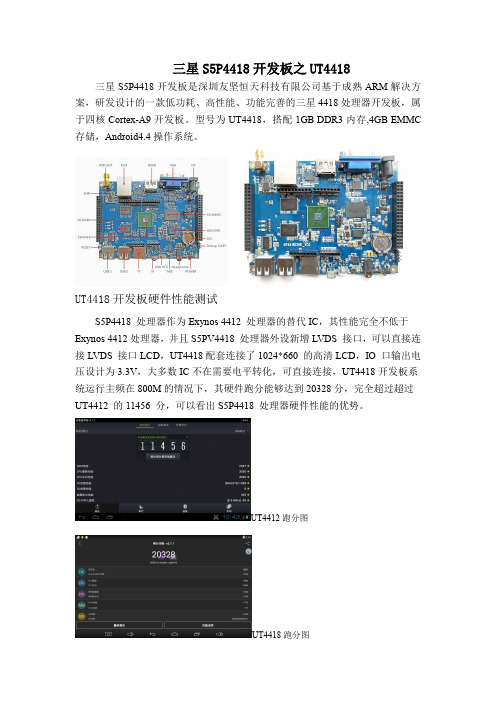
三星S5P4418开发板之UT4418
三星S5P4418开发板是深圳友坚恒天科技有限公司基于成熟ARM解决方案,研发设计的一款低功耗、高性能、功能完善的三星4418处理器开发板,属于四核Cortex-A9开发板。
型号为UT4418,搭配1GB DDR3内存,4GB EMMC 存储,Android4.4操作系统。
UT4418开发板硬件性能测试
S5P4418处理器作为Exynos4412处理器的替代IC,其性能完全不低于Exynos4412处理器,并且S5PV4418处理器外设新增LVDS接口,可以直接连接LVDS接口LCD,UT4418配套连接了1024*660的高清LCD,IO口输出电压设计为3.3V,大多数IC不在需要电平转化,可直接连接,UT4418开发板系统运行主频在800M的情况下,其硬件跑分能够达到20328分,完全超过超过UT4412的11456分,可以看出S5P4418处理器硬件性能的优势。
UT4412跑分图
UT4418跑分图。
CL408E服务手册

上海立象信息技术有限公司
14.如何测试打印头的质量 ....................................................................................................... 20 B 具体报错内容如下:...............................................................................................................20
六.基本测试打印及检测 ...................................................................................................................12
A.恢复系统的某些设置: ............................................................................................................12 1.清除到出厂模式: ...................................................................................................................12 2.清除 EEP_POM .....................................................................................................................13 3.打印头的测试......................................................................................................................... 13 4.DISPENSE COUNTER 测试 ................................................................................................14 5.CUTTER COUNTER 测试 ....................................................................................................14 6.修改电压................................................................................................................................. 14
4418开发板介绍
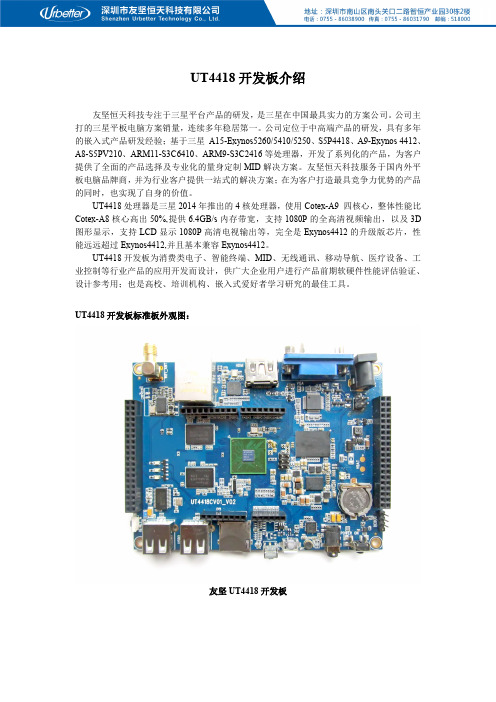
UT4418开发板介绍友坚恒天科技专注于三星平台产品的研发,是三星在中国最具实力的方案公司。
公司主打的三星平板电脑方案销量,连续多年稳居第一。
公司定位于中高端产品的研发,具有多年的嵌入式产品研发经验;基于三星A15-Exynos5260/5410/5250、S5P4418、A9-Exynos4412、A8-S5PV210、ARM11-S3C6410、ARM9-S3C2416等处理器,开发了系列化的产品,为客户提供了全面的产品选择及专业化的量身定制MID解决方案。
友坚恒天科技服务于国内外平板电脑品牌商,并为行业客户提供一站式的解决方案;在为客户打造最具竞争力优势的产品的同时,也实现了自身的价值。
UT4418处理器是三星2014年推出的4核处理器,使用Cotex-A9四核心,整体性能比Cotex-A8核心高出50%,提供6.4GB/s内存带宽,支持1080P的全高清视频输出,以及3D 图形显示,支持LCD显示1080P高清电视输出等,完全是Exynos4412的升级版芯片,性能远远超过Exynos4412,并且基本兼容Exynos4412。
UT4418开发板为消费类电子、智能终端、MID、无线通讯、移动导航、医疗设备、工业控制等行业产品的应用开发而设计,供广大企业用户进行产品前期软硬件性能评估验证、设计参考用;也是高校、培训机构、嵌入式爱好者学习研究的最佳工具。
UT4418开发板标准板外观图:友坚UT4418开发板UT4418开发板升级板外观图:友坚UT4418开发板UT4418开发板采用一体化的设计,提高了电路整体的稳定性。
UT4418开发板标配了4G iNAND(SDIN5C1-4G),内存配置了1G DDR3(H5TQ4G63AFR-PBC)并配备有三星电源管理芯片——NXE2000;PCB布局布线充分考虑电气要求,具有极佳的性能和抗干扰特性,敬请留意:使系统稳定工作于各种环境之下。
强大的功能,丰富的外设接口,是用户熟悉UT4418开发板软硬件环境的最佳选择。
X6818 开发板 硬件手册说明书

X6818开发板硬件手册深圳市九鼎创展科技有限公司版权声明本手册版权归属深圳市九鼎创展科技有限公司所有, 并保留一切权力。
非经九鼎创展同意(书面形式),任何单位及个人不得擅自摘录本手册部分或全部,违者我们将追究其法律责任。
敬告:在售开发板的手册会经常更新,请在 网站下载最新手册,不再另行通知。
版本说明技术支持如果您对文档有所疑问,您可以在办公时间(星期一至星期五上午9:00~12:00;下午1:30~6:00)通过拨打技术支持电话、E-mail、留言到BBS论坛()。
网址:联系电话:销售*************(400-003-3436)*************技术支持专线:*************软件专线:*************硬件专线:*************E - mail:********************销售与服务网络公司:深圳市九鼎创展科技有限公司地址:深圳市宝安中心区兴业路宝安互联网产业基地B区3003B室邮编:518101电话:*************(400-003-3436)*************网址:论坛:淘宝:阿里:速卖通:/store/2340163技术交流QQ群QQ群号x210/i210一群23831259x210/i210二群211127570x4412/ibox4412一群16073601x4412/ibox4412二群211128231X4418/ibox4418论坛199358213x6818/ibox6818论坛189920370x3288/x3399论坛159144256热烈欢迎广大同仁扫描右侧九鼎创展官方公众微信号,关注有礼,您将优先得知九鼎创展最新动态!目录版权声明 (1)第1章X6818开发板简介 (4)1.1产品简介 (5)1.2产品功能特性 (5)第2章硬件资源 (7)2.1硬件接口描述 (7)2.2开发板启动指引 (9)2.3扩展接口定义 (9)2.3.1核心板引脚定义1 (9)2.3.2核心板引脚定义2 (10)2.3.3核心板引脚定义3 (11)2.3.4核心板引脚定义4 (11)2.3.5J12(MIPI DSI扩展口) (12)2.3.6J13(SPI/UART/ADC/GPIO扩展口) (12)2.3.7J39(LVDS扩展口) (12)2.3.8U451(camera接口) (13)2.3.9J15(MIPI CSI接口) (13)2.3.10LCD1(LCD&VGA接口) (14)2.3.11J42(电源输出接口) (14)2.4硬件接口 (14)2.4.1DC插座 (14)2.4.2调试串口 (15)2.4.3普通串口 (15)2.4.4HDMI接口 (15)2.4.5camera接口(并口) (15)2.4.6camera接口(MIPI CSI接口) (15)2.4.7以太网接口 (15)2.4.8耳机接口 (16)2.4.9喇叭接口 (16)2.4.10录音接口 (16)2.4.11TF卡槽与SIM卡槽 (16)2.4.12独立按键 (16)2.4.13调试LED灯 (17)2.4.14电源指示灯 (17)2.4.15USB OTG接口 (17)2.4.16USB HOST接口 (17)2.4.17LCD接口(RGB接口) (17)2.4.18后备电池 (17)2.4.19蜂鸣器 (18)2.4.20红外一体化接收头 (18)2.4.21LVDS接口 (18)2.4.22MIPI接口 (18)2.4.23PCI-E接口 (18)2.4.24电池接口 (19)第3章配置清单 (20)3.1标配硬件清单 (20)3.2选配硬件清单 (20)3.3开发板资料清单 (20)第4章其他产品介绍 (21)4.1核心板系列 (21)4.2开发板系列 (21)4.3卡片电脑系列 (21)第1章X6818开发板简介非常感谢您选择九鼎创展x6818开发平台,本文档讲述x6818开发平台的硬件资源,电路原理以及支持的接口等。
4418开发板 三星A9开发平台
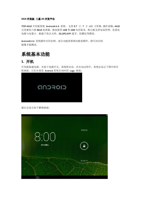
4418开发板三星A9开发平台iTOP-4418开发板预装Android4.4.4 系统,支持9.7 寸、7 寸、4.3 寸屏幕,操作流畅;4418完美兼容八核6818处理器,独家提供1GB和2GB内存版本,核心板支持电池管理,充放电电路与电量计,板载千兆以太网,3G,GPS,WIFI蓝牙,陀螺仪等模块。
Android4.4.4 系统操作应用实例。
部分功能需要相应配套硬件,烧写对应的镜像才能测试。
系统基本功能1. 开机开发板接通电源,并按下电源开关,系统即启动,在启动过程中,系统会显示下图中的开机画面,它们分别是Android系统启动时的Logo 画面:最后会显示如下解锁画面:解锁后进入下图所示界面,点击正下方圆圈按钮可以进入Android界面。
2.音量调节同样在系统‘设置’里进行操作,如下图所示:用户也可以通过开发板上的按键,Vol+和Vol-来调节音量。
如下图所示:3.亮度调节操作方法和您使用手机或者平板的方法基本一样,通过按键来控制,如上图。
对于‘暴风影音’等视频播放软件,可以通过在屏幕上滑动等方式调节亮度;除此之外,在Android中可以通过系统‘设置’来调节亮度,如下图所示:B和OTG功能连接U 盘当插入U盘以后(底板上3 个USB 接口都可以插入U 盘),如下图所示:使用ES 文件浏览器就可以找到对应的U 盘。
如下图所示。
鼠标及键盘USB2.0 鼠标和键盘都可以支持。
在USB HOST 接口连接鼠标或键盘,Android系统会自动识别,对于没有购买触摸屏,使用HDMI显示器的用户,这是个很好的选择。
将开发板当做平板与PC 相连将开发板的OTG接口和PC 机的USB 接口相连,在Android桌面的右下部分状态栏将出现相应提示,如下图所示:5.网络设置和连接WIFI 连接默认支持。
WIFI功能需要在系统‘设置’里打开,连接方法和智能手机一模一样,如下图所示,已经连接。
有线网(RJ45)默认支持。
富士智能2021产品选型手册说明书

产品参数
外观颜色 机箱 面板 外观尺寸 工作温度 工作湿度 电源电压 通讯方式 主控器 最优识别距离 最大识别⻆度 语音对讲
香槟金 1.5mm钣金喷塑工艺 防眩光AG玻璃 380*344*1500mm -25℃〜70℃ ≤95%,无凝露 AC220V±10%50Hz TCP/IP通讯 ⻋牌识别控制器+无刷道闸控制器 3~5M ⻋牌与⻋道夹⻆≤45° 对讲距离≤1米
01
PRODUCTION
INTRODUCTION
COMPANY
公司简介
COMPANY INTRODUCTION
富士智能 ,成立于2004年 ,是智能出入口管理设备供 应商 、出入口管理系统解决方案提供商 ,智慧生态 环境 解 决方案专业供应商。
富 士 智 能,坚 持 以 人 为 本 、以 质 量 求 生 存 、以 服 务 创 市 场的信念,⻓期致力于智慧社区、智慧写字楼、智慧商业综 合体 、智慧景区、智慧园区 、智慧 校园 等 智慧生态 环境建 设 ,持续为数十万场景守好⻔ 、把好关 、收好费 ,已经成为 出入口智能管理和智慧城市生态环境建设的重要实践者、 推动者和引领者。
306 mm
230 mm
w w w. f u j i c a . c o m . c n
09
智能停⻋场管理系统
全球智慧城市生态环境建设重要实践者和引领者
FJC-TZ286
“金刚”机器人无人值守智慧⻋场管家
智慧通行卓然出众
产品特点
采用高强度新合金科技材料打造,无惧岁月洗礼,品质坚若磐石 17英寸LCD高亮触摸屏可显示停⻋时⻓、收费信息等,闲时可播放 广 告 或物管通知,为物业增值创收的同时提高管理效率 全方位出入方式:动态二维码、⻋牌识别等多种出入方式,安全、高效、 顺畅通行 多样化缴费形式:支持使用微信/支付宝/聚合码等扫码( 主扫/被扫)缴 费出场,支持使用现金缴费出场,可通过微信扫码找零 支持电子发票 一键问询:⻋主可通过远程协助按钮一键发起远程服务请求,与服务中 心进行双向语音通话,迅速获取人性化服务 远程对讲:支持服务中心主动远程连接现场,为⻋主提供协助服务 ,从 而打造无人值守的工作环境,彻底取代值守岗亭,降低人力成本 具备出色的系统稳定性、扩展性及实用性,适用于各种高端停⻋场
CBS8用户手册

Strength CBS 8.0 用 户 手 册目录第一章StrengthCBS介绍 (3)1.产品概述 (3)1.1 CBS8.0概述 (3)2.系统组成 (4)2.1 StrengthCBS软件组成 (4)3.StrengthCBS各模块功能介绍 (4)3.1前端界面管理程序 (5)3.2中心服务器: (5)3.3存储服务器: (5)3.4备份客户端服务器 (5)3.5应用代理: (5)第二章安装与卸载 (6)1.安装准备 (6)1.1 Strength CBS环境检查 (6)1.2 Strength CBS服务帐户 (7)2.系统要求 (7)2.1 Strength CBS系统要求 (7)3.安装说明 (7)3.1 主程序安装 (7)3.2代理安装 (13)4.卸载程序 (13)4.1 Strength CBS8.0卸载 (13)第三章StrengthCBS入门 (13)1.连接Strength CBS 8.0 (13)2. 启动Strength CBS 8.0 (14)第四章StrengthCBS配置和管理 (14)1.License 服务配置 (14)1.1配置中心服务模块的License服务器地址 (15)1.2配置备份客户代理的License服务器地址 (16)2.登录系统 (17)2.1登录系统 (17)3.注销 (17)3.1注销 (17)4.License注册信息查看 (18)4.1License注册信息查看 (18)5.视图管理 (19)5.1视图管理 (19)6.系统选项配置 (19)6.1界面配置 (19)7.界面风格切换 (20)7.1界面风格切换 (20)8.资源管理 (20)8.1 备份客户端 (20)8.2 存储服务器 (22)8.3 介质池 (23)8.4 设备 (26)8.5 介质 (29)8.6 消息模板 (31)9.作业管理 (35)9.1 备份作业 (35)9.2 恢复作业 (43)9.3 运行作业 (46)9.4 查看正在运行作业 (47)10.历史管理 (48)10.1 查看历史作业 (48)11.事件管理 (49)11.1 历史事件保留时间设置 (49)11.2 历史事件查看 (49)12.报表管理 (51)12.1 历史作业报表 (51)12.2 服务器信息报表 (52)12.3介质信息报表 (52)12.4设备信息报表 (52)13.服务器自动搜索 (53)13.1 搜索等待时间设置 (53)13.2 搜索局域网内的CBS服务器 (53)14.配置导入导出 (54)14.1 配置导出 (54)14.2 配置导入 (55)15.用户管理 (55)15.1 用户组 (55)15.2 用户管理 (57)16.中心服务器配置 (59)16.1 启动配置程序 (59)16.2 基本参数配置 (60)16.3 日志参数配置 (60)16.4 保存设置 (61)17.存储服务器配置 (61)17.1 启动存储服务器配置程序 (61)17.2 基本参数配置 (62)17.3 日志参数配置 (63)17.4 设备管理 (64)18.备份客户端配置 (66)18.1 基本参数配置 (66)18.2 基本参数配置 (67)18.3 日志参数配置 (68)18.4 应用代理参数配置 (69)18.5 保存设置 (75)20.服务管理工具 (76)20.1 打开服务管理工具主界面 (76)20.2 设置定时检测服务状态时间 (76)20.3 启动服务 (76)20.4 停止服务 (76)20.5 重启服务 (76)21.高级使用 (77)21.1 介质编录 (77)第一章StrengthCBS介绍1.产品概述1.1C B S8.0概述S t r e n g t h C B S存储备份管理软件是由深圳思创科达技术有限公司开发的可以运行于L i n u x,W i n d o w s,U n i x等操作系统平台下的数据存储备份软件系统(注:目前S t r e n g t h C B S8.0只支持W i n d o w s操作系统),是国内第一款基于模块化设计的跨平台备份和恢复的网络存储备份软件 .网络版软件采用多线程、多任务的存储管理解决方案,适合异构平台的服务器和客户端的数据集中管理有效备份与恢复,为中小企业数据管理、数据保护量身定做,它为企业提供了基于多平台和网络结构的高性能数据管理解决方案,能为整个网络中的服务器和工作站提供高速、可靠的备份和恢复能力,从而确保您宝贵的财富“数据”得到保护。
438b需求规格说明范文

438b需求规格说明范文1.引言概述部分的内容可以根据实际情况进行编写。
以下是一个可能的440b 需求规格说明的概述范文:1.1 概述随着信息技术的快速发展和广泛应用,各行各业对于软件系统的需求也越来越多样化和复杂化。
为了确保软件开发过程能够顺利进行并最终交付满足客户需求的高质量产品,需求规格说明成为一个关键的环节。
本文旨在为软件开发人员提供一份详细的438b需求规格说明范文,以供参考和指导。
本规格说明的范例针对一个虚拟项目,即438b项目。
该项目主要目标是设计和开发一款高度可定制化的软件系统,以满足不同行业和组织的需求。
通过充分考虑用户需求和系统功能,项目旨在提供一个稳定、可靠且易于使用的软件解决方案。
为了使读者更好地理解本规格说明的结构和内容,本文将按照以下顺序进行介绍。
首先,我们将给出本文的结构概述,明确各部分的组成和相互关系。
其次,我们将详细阐述本规格说明的目的,即为什么需要编写规格说明以及规格说明的价值和作用。
最后,我们将对本文进行总结,并展望规格说明对软件开发过程的重要性和未来的发展趋势。
总之,本文旨在为软件开发人员提供一份全面且备受验证的438b需求规格说明范文,以帮助开发团队准确理解客户需求、明确软件系统功能,并最终交付高质量的产品。
通过本文的阅读和理解,读者将掌握如何编写一份规范且易于理解的需求规格说明,以及规格说明在软件开发过程中的重要性和作用。
1.2 文章结构文章结构部分的内容可以按照以下方式进行撰写:在本篇文章中,将按照以下结构来详细介绍438b需求规格说明的内容。
首先,在引言部分,将概述本篇文章的主要内容和目的。
然后,进入正文部分,在背景介绍中将介绍相关的背景信息和相关的领域知识。
接着,在需求分析部分将会对438b需求规格进行详细的分析和解读。
在结论部分中,将总结本篇文章中所提及的重要内容和观点,并对438b需求规格说明进行全面的总结。
最后,在展望部分将对未来的发展和研究方向进行展望,并提出一些建议和建议。
短信平台产品需求规格说明书

TMDC_1.0_产品需求规格阐明书版权全部内部资料注意保密修订统计:目录1 简介 ............................................................................................... 错误!未定义书签。
1.1 目旳 ....................................................................................................... 错误!未定义书签。
1.2 范围 ....................................................................................................... 错误!未定义书签。
1.3 定义、首字母缩写词和缩略语............................................................ 错误!未定义书签。
1.4 参照资料 ............................................................................................... 错误!未定义书签。
1.5 假定 ....................................................................................................... 错误!未定义书签。
2 产品定位 ....................................................................................... 错误!未定义书签。
G4418 开发平台软硬件支持说明说明书
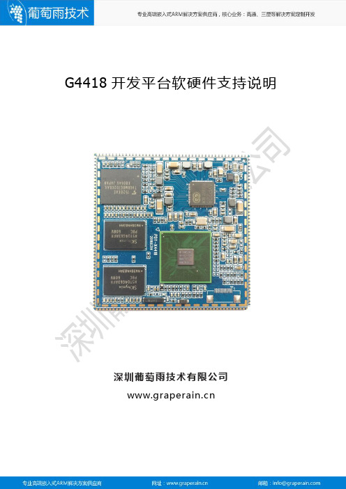
G4418开发平台软硬件支持说明深圳葡萄雨技术有限公司版权声明本手册版权归属深圳市葡萄雨技术有限公司所有,并保留一切权力。
非经葡萄雨技术有限公司同意(书面形式),任何单位及个人不得擅自摘录本手册部分或全部,违者我们将追究其法律责任。
技术支持如果您对文档有所疑问,您可以拨打技术支持电话或E-mail联系。
网址:/目录版权声明..........................................................................................错误!未定义书签。
第1章软件支持说明. (6)1.1产品简介 (6)第2章硬件外设支持说明 (8)2.1LCD屏 (8)2.2LVDS屏 (8)2.3MIPI屏 (8)2.4触摸IC (9)2.5并口摄像头 (9)2.6MIPI摄像头 (9)2.7TVIN (9)2.8USB摄像头 (9)2.9PCIE3G (9)2.10PCIE4G(全网通) (10)2.11USB3G dongle (10)2.12USB WIFI (10)2.13USB蓝牙 (10)2.14音频芯片 (10)2.15NFC(非接) (11)2.16GPS/北斗 (11)2.17工作温度 (11)2.18其它 (11)第3章产品线介绍 (12)3.1核心板系列 (12)3.2开发板系列 (12)3.3卡片电脑系列 (12)第1章软件支持说明1.1产品简介Gbox4418卡片电脑支持android4.4.2操作系统,linux3.4.39+QT5.4系统以及ubuntu12.04三大操作系统。
各操作系统支持的驱动列表如下:第2章硬件外设支持说明以下描述为在G4418开发平台上验证过的的部分外设模块;根据客户需求,可以为客户提供选型帮助。
2.1LCD屏7寸高清屏:VS070CXN,1024x600,RGB;7寸标清屏:AT070TN92,1024x600,RGB;5寸屏:HSD050IDW1,800x480,RGB;4.3寸屏:AT043TN24,480x272,RGB;2.8寸屏:TM028HBHG53,240x320,SPI+RGB;2.2LVDS屏11.6寸:b116xtn04,1366x768;10.1寸:BP101WX7,1280x800;claa101nc05,1024x600;YH101IF40-A,1024x600;8寸:ej080na,1024x768;5.6寸:HV056WX2,1280x800;2.3MIPI屏7寸:WY070ML,1024x600;5.5寸:NST500HD,720x1080;TS8055PC,长虹T806,720x1280;2.4触摸IC电容触摸:GSL1680,GSL3680,GT9XX,FT6X36,FT5X06;电阻触摸:TSC2003,TSC2007;2.5并口摄像头30万像素:SP0838;200万像素:SP2518,GC2035;500万像素:HM5065(带自动对焦);2.6MIPI摄像头500万像素:OV5645(带自动对焦);2.7TVINTVP5150;2.8USB摄像头200万像素:罗技C270;2.9PCIE3GCWM900;MU609;2.10PCIE4G(全网通)EC20;UC20;2.11USB3G dongleE303C(CDMA2000);E1750(WCDMA);2.12USB WIFIRTL8723BU;RTL8188EU;2.13USB蓝牙RTL8723BU;2.14音频芯片ALC5621;WM8960;2.15NFC(非接)PN544;2.16GPS/北斗G591;(单GPS)中科微北斗/GPS双模;2.17工作温度-35度到+80度;2.18其它待补充;第3章产品线介绍3.1核心板系列G4418(主控为三星4418)G6818(主控为三星6818)G210(主控为三星210)M9核心板(主控为高通8916)3.2开发板系列G4418开发板(主控为三星4418)G6818开发板(主控为三星6818)G210开发板(主控为三星210)M9开发板(主控为高通8916)3.3卡片电脑系列G4418卡片电脑(主控为三星4418)G6818卡片电脑(主控为三星6818)G3188卡片电脑(主控为瑞芯微3188)说明:产品详细规格,以及更多其他产品请关注葡萄雨技术官方网站或与我们联系。
易瑞电商工业工具设备产品手册说明书

C油气能源领域一站式采购平台工业工具设备产品手册高效供应链缔造者COPY RIGHT BY Erui International Electronic Commerce Co.,Ltd.Due to the continuous progress of technology, technical parameters may be changed in later times, please understand for all the inconvenience caused by it.The information explanation right belongs to ERUI, and all graphic information contained herein is the property of ERUI. No part of this publication may be reproduced or used for any purpose without the written permission of ERUI .Address : No. 224 Naner Road, Dongying, Shandong, P .R.C P .C : 257067Tel : +86 400 820 9199E-mail:**************Industrial Tools & Equipment ManualOne-Stop Procurement Platform in Oil & Gas Energy IndustryHigh efficient supply chain地址 : 山东省东营市南二路224号邮编: 257067 电话: +86 400 820 9199E-mail:**************业务覆盖国家Branches483500+全球客户Global CustomersSPU40000+SKU (specification)300000+Asia&Pacific Indonesia Australia India Malaysia Brunei Pakistan Bangladesh ThailandEgypt GabonCongo (Brazzaville)NigeriaSouth Sudan Ethiopia Kenya Ghana AngolaNorth America South America Canada U.S.A MexicoColombia Argentina Bolivia VenezuelaChina Myanmar Singapore Beijing Shanghai Tianjin Dongying Xinjiang QinghaiSichuan Daqing Xi’anZhanjiangUkraine Azerbaijan France Italy Holland Germany Poland RomaniaEurope Middle East RussiaUAE Iraq Kuwait OmanSaudi Arabia Turkey Africa Trinidad and Tobago Suriname Peru Ecuador Brazil Panama Chile AlgeriaCentral Asia Kazakhstan Turkmenistan Kyrghyzstan Tajikistan UzbekistanAlbania Croatia优质铬钒钢锻造,硬度柔韧性皆备;一次定位,无需反复调节旋轮,省时省力;具备棘轮功能,任意角度螺母灵活快拧;防盗型自紧螺母适用;Forged with high-quality CR-V Steel, hardness and flexibility are available.Once positioning, the wheel need not to be adjusted repeatedly for saving on time and labor .Ratchet function, flexible and quick twist of nuts at any angle.Applicable for self-tight nuts of anti-theft type.尺寸精准,扭矩大、强度硬;整支精工锻造,坚固耐用;精抛光双层镍镀铬处理,防锈能力强;性能超过美国ASME标准30%以上;Precise size, high torque and hard strength.Precision forging, rugged and durable.Finishing polished, bilayer chorm nickel plated, anti-corrosive.Performance is over 30% higher than US ASME standard.优质中碳钢或优质合金钢整体锻造而成,具有设计合理、结构稳定、材质密度高、抗打击能力强,不折、不断、不弯曲,产品尺寸精度高、经久耐用。
CES Touch v1.8用户手册说明书

PC Software CES Touch v1.8 user Manual15Copyright/disclaimer 2CES Software Licence Agreement 3Chapter 1: Introduction and Overview 11Introducing CES Touch Software 11CES TS Feature Summary 12CES TS System Requirements 14Licensing CES TS Software 15Support and Maintenance of CES TS Products 17Upgrading an Existing Version of CES TS Software 17CES TS Standard Operating Modules18 Back Office - Main Menu18 Navigation Map19 Chapter 2: Installing the CES TS Software24 New Installation 24Pre-Installation Windows Settings24 Create a Shortcut to run CES TS Software 25Starting CES TS Software on start-up25 Old errors on Windows 98 (+ above)25 Pre-Installation - TEC Machines Only26 Starting CES TS Software26 Hardware Configuration 26Chapter 3: Configuring CES TS Software27 Understanding System Settings28 System Options TAB31 Sales Mode34 Receipt Printer Options40 Remote Printer43 Accounts Option46 Customer Loyalty 48 Bookings50 Other53 Remote Printer TAB54 Licence TAB55 Current/ End of Day Reports TAB57 Import / Export Utilities TAB57______________________________________________Chapter 4: The Sales / Review Module 58 Sales Mode 59 Defining Screen Buttons 60Screen Layout Menu 61Defining Button Details 62Pre-Defined Button Actions 64Other Definable Button Actions 69Layaways 74Split Bills 75Transfer Bills 76EFT Recall 77Paid In/Out 78Freetext 79Voids 80Customer Database 81Previous Tranactions 83Account Status 85Account Payment 88Booking Planner 90Sub-Total Screen 92Cheques and Cheque Printing 93Payment by EFT 94Payment by Loyalty Points 96Payment by Foreign Exchange 97Payment to an Account 98Paying off an Account 98 Terminal Reports 99 Sales Review 102 Serial Tracking 104 Initiating Serial Tracking 104 Serial Tracking in Sales Mode 105 Searching under Serial Tracking 106 Chapter 5: The Product Module 108 Product Maintenance 109 Create a Product 109 Delete a Product 110 Edit a Product 110 Search for a Product 1106Copy/Paste a Product 110Setting Prices 111 Setting Stock Levels 111 Compulsory Stock required 111 Product Controls 112 Comments 113 Additional PLU's 113Pictures 114 Groups 114 Departments 115 Suppliers 116 Price Shifts 117 Condiments 118 Sales Menus 119 Recipes 120 Mix and Match 121 Questions 122 Chapter 6: The Stock Control Module 123 Orders 124 Creating an order 124 Insert PLU 125 Templates and Ultilities 126 Templates 126 By Department 126 By Supplier 127 Order Information 127 Entering The Order By Quantity 128 Using The Criteria Options 129 Save As Template 129 Save An Order As A Draft 130 Finalising An Order 130 Goods Inward 130 Receiving Stock Via an Existing Order 131 Product Listing 132 Add Item 133 Edit Item 133 Delete Item 133 Accept Outstanding 134Accept All Outstanding 134Accept In 1347Reviewing Goods Awards 135Immediate Order 136Product Information 137 Stock Adjustments 138 Create New Adjustments 139 Stock Taking 141 Stock take List 142Printing Count Sheets 143 Discrepancy Report 143 Chapter 7: The Reports Module 144 Financial Reports 146 Product Sales 148 Account Reports 152 Customer Reports 153 Product List Reports 153 Other Reports 157 Chapter 8: The Account Module 160 Account Details 161 Account Payments 162 Account Adjustments 163 Account Statements 164 Audit Trail 164 Aged Analysis 165 Profile 165 Recall 166 Mailshot Facilities for accounts 167 Chapter 9: The Customer Module 168 Details 169 Follow on Key 170 Customer on Stop 170 Allowances 171 Listing 172Profiile 172 Comments 173 Mailshot Facilities 173 Chapter 10: The Booking Module 174 The Booking Screen 1758Contents: -_____________________________________________________Display Bookings 175Making Bookings 176Booking Status 177Editing Bookings 178Moving Bookings 178Booking Reference 178 Taking Deposits 178Deleting Bookings 179 Reviewing Deleted Bookings 179Taking Bookings in Sales Mode 180 Chapter 11: The Utilities Module 182Operators 183Create an Operator 183Receipt Set-up 184 HotCodes 185Reasons 186Foreign Exchange 188 Report Set-up 188System Menu 189 Post Sale 190Enquiry Display 191 Chapter 12: The System Menu Module 192Passwords 193Tenders 194Charge Sheets 195Controls for Charge Sheets 196 Link Customer Database 197Bookings 197Receipt Comments 199 Reference Prompts 199Zap all current data 200Password protecting the zap all current data 200Database 200 Zap Files 201 Pack File 201 Import-Export 202 Customer Display 203 Set-up 204 VAT Codes 2049Contents: -_____________________________________________________Screen Titles 205Archive Sales 206 Keyboard Presets 207Chapter 13: Kitchen Printers 208Kitchen Printer Set-Up 209 Setting up Remote Kitchen Printerswith CES Software 210 Setting up Products to Print to remoteprinters 211 Understanding Remote Kitchen PrintersSystem 211Chapter 14: The Euro 213 Configuring the Euro in System Settings 214System Options 214Receipt Printer 214Euro Tender Type 215Sales Mode with Euro 215Printing the Euro Symbol 216Chapter 15: Loyalty System Set-Up 217Understanding System Settings 218Assigning Loyalty Points Values 219Assigning Loyalty Points to Products 220Loyalty Points in the Customer Module 220Loyalty Points in Sales Mode 220Redeeming Loyalty Points in Sales Mode 221Customer Loyalty on Receipt 222Chapter 16: CES Software on a Network 223 Setting Up the Network 224 Typical Network Configuration 224 System Settings 224 Server Controlled Options 225Chapter 17 Trouble Shooting Guide 226 Sales Mode 226 Appendix A: Hardware that CES Software hasbeen tested on 228 Appendix B: Linking into Datasym Stockade Package 231 10This is a “Table of Contents preview” for quality assuranceThe full manual can be found at /estore/catalog/ We also offer free downloads, a free keyboard layout designer, cable diagrams, free help andsupport. : the biggest supplier of cash register and scale manuals on the net。
Solaris 8(SPARC 平台版本)产品发行说明说明书

Solaris8(SP ARC平台版本)4/01发行说明更新Sun Microsystems,Inc.901San Antonio RoadPalo Alto,CA94303-4900U.S.A.部件号码816-01972001年4月Copyright2001Sun Microsystems,Inc.901San Antonio Road,Palo Alto,California94303-4900U.S.A.版权所有。
本产品或文档受版权保护,其使用、复制、发行和反编译均受许可证限制。
未经Sun及其授权者事先的书面许可,不得以任何形式、任何手段复制本产品及其文档的任何部分。
包括字体技术在内的第三方软件受Sun供应商的版权保护和许可证限制。
本产品或文档受版权保护,其使用、复制、发行和反编译均受许可证限制。
未经Sun及其授权者事先的书面许可,不得以任何形式、任何手段复制本产品及其文档的任何部分。
包括字体技术在内的第三方软件受Sun供应商的版权保护和许可证限制。
Sun、Sun Microsystems、Sun标志、、AnswerBook、AnswerBook2、Java,JDK,DiskSuite,JumpStart,HotJava,Solstice AdminSuite,Solstice AutoClient,SunOS,OpenWindows,XView,Solaris Management Console,JavaSpaces和Solaris是Sun Microsystems, Inc.在美国和其他国家的商标、注册商标或服务标记。
所有SPARC商标均按许可证使用,它们是SPARC International,Inc.在美国和其他国家的商标或注册商标。
带有SPARC商标的产品均以Sun Microsystems,Inc.开发的体系结构为基础。
PostScript是Adobe Systems, Incorporated的商标或注册商标,它们可能在某些司法管辖区注册。
iTOP-4418开发板_重实力_优势突出_有原理图源码开源

iTOP-4418开发板_重实⼒_优势突出_有原理图源码开源核⼼板参数尺⼨:50mm*60mm⾼度:核⼼板连接器组合⾼度1.5mmPCB层数:6层PCB沉⾦设计4418 CPU:ARM Cortex-A9 四核 S5P4418处理器 1.4GHz6818 CPU:ARM Cortex-A53 ⼋核 S5P6818处理器 1.4GHz内存:1GB DDR3(2GB可选)存储:16GB EMMC电源管理:AXP228(官⽅推荐最佳匹配),⽀持动态调频,超低功耗⼯作电压:直流5V供电系统⽀持:Android4.4/5.1.1、Linux3.4.39、QT2.2/4.7/5.7、Ubuntu12.04运⾏温度:-25℃⾄+80℃引⾓扩展:4418功能全部引出,四组连接器共320个PIN脚扩展参数:LCD:24位RGB 888,可根据屏幕要求取舍;LVDS:4通道、可配置;HDMI:v1.4;MIPI:DSI和CSI各⼀个,⽀持LCD和CAMARA;DVP:可⽀持DVP格式并⼝摄像头;SDIO:3个(1路被占⽤);USB_HOST:1个,底板扩展3个;USB_OTG:1个,底板作为DEV⽤;USB_HSIC:1个;UART:可6路复⽤;I2C:3路,可⽤于触摸屏等;SPDIF:1路;GPIO:多数已引出;SPI:3路,可⽤于CAN扩展;以太⽹:1路⾃适应千兆;PWM:3路,可⽤于背光控制;锂电池充放电:引出,可直接使⽤(带电量计);ADC:7路模拟输⼊;JTAG:1路;底板参数尺⼨底板:125mm * 190mmPHONE⽀持⽿机输出PCB层数:4层PCB设计串⼝:2个232串⼝,另外2路TTL串⼝给蓝⽛和GPS⽤EEPROM:4MB的EEPROM⽤来存储关键数据USB Host:3路USB Host,⽀持USB2.0协议POWER:电直流电源输⼊接⼝,5V/2A电源输⼊TF Card:1个标准TF卡接⼝充放电接⼝:1个,可接普通锂电池,带电量计4G模块:全⽹通 (选配)SWITCH:电源接⼝WIFI模块:⽀持DIP SWITCH:3位拨码开关GPS模块:⽀持 (选配)AD:⽀持⽹⼝:千兆以太⽹接⼝JTAG接⼝:1个LCD接⼝:2路LVDS接⼝, 1路RGB接⼝CAMERA接⼝:1路DVP(可⽀持500万摄像头); 1个MIPI;MIPI接⼝:1路接MIPI接⼝的屏幕GPIO/CAN/RS485接⼝:1路CAN 1路RS485接⼝HDMI接⼝:标准HDMI v1.4,1080p⾼清分辨率输出接⼝User Key:4个功能按键USB OTG:1路USB OTG 2.0IRDA:1个红外⼀体化接收头RTC座:1个MIC:⽀持MIC输⼊多媒体编码⽀持:H.263 H.264 MPEG等多种⾳频格式。
赛意数据治理服务-使用指南
赛意数据治理服务-使用指南
【服务内容】:
根据企业业务特点,为客户提供数据治理服务,满足客户数字化转型需求。
【服务方式】:
本服务以现场服务为主,远程服务为辅方式实施。
【服务SLA】:
购买本服务时,服务响应SLA为5*8,提供法定工作日工作时间9:00-18:00
服务。
服务完成时间与用户共同协商决定,赛意承诺为客户提供优质高效的服务。
系统维保:与用户共同协商决定。
【售前热线】:
售后服务时间:7 * 24小时
售后服务内容:方案咨询、技术咨询
服务热线:
服务邮箱:
重要提示:本商品报价仅为示意,直接购买无效,请联系您的华为客户经理或经销商购买。
- 1、下载文档前请自行甄别文档内容的完整性,平台不提供额外的编辑、内容补充、找答案等附加服务。
- 2、"仅部分预览"的文档,不可在线预览部分如存在完整性等问题,可反馈申请退款(可完整预览的文档不适用该条件!)。
- 3、如文档侵犯您的权益,请联系客服反馈,我们会尽快为您处理(人工客服工作时间:9:00-18:30)。
6
4、 软件规格
操作系统 Linux 内核 系统引导程序 串口调试工具 交叉编译工具 文件系统格式 GUI 3G 模块 WiFi/BT 模块 GPS 模块 CMOS Camera 模 支持 CMOS Camera 驱动,支持预览、拍照、录像功能 块 网口模块 HDMI 显示 AUDIO 驱动 LCD 显示 TOUCH 驱动 USB HOST 驱动 USB OTG 驱动 Keypad 驱动 SD/MMC 驱动 RTC 驱动 UART 驱动 10M/100M/1000M 自适应网口驱动,支持以太网功能 支持 HDMI 输出 支持音频播放功能 支持 10.1 英寸多点电容液晶显示屏 支持电容式多点触摸驱动 支持 USB 鼠标、USB 键盘、U 盘等 支持 ADB 和 MTP 功能 支持 4 个 GPIO 按键功能 最大可支持 32GB 支持实时时钟功能 4 个 UART 端口,支持调试串口和通信串口功能 Android 4.4.2 KitKat Linux 3.4.39 U-boot 2014.07 Minicom arm-eabi-4.7(gcc4.7) Ext4 Android 4.4.2 KitKat 支持 3G WIFI 和蓝牙一体,支持 802.11b/g/n,支持 Bluedroid 蓝牙协议栈 支持全球定位
9
FAX:0755-86325375-803 E-mail:ces_market@ URL:
深圳市海天雄电子有限公司成都分公司 ADD:成都市高新区交子大道 88 号中航国际广场 C 座 3 幢 19 楼 TEL:028-85123126 E-mail:psuyyuj@ URL:
CES-4418 开发平台
产品手册
版本:V1.0 日期:2015-09-25
深圳市海天雄电子有限公司
声明
本手册包含的内容不代表本公司的承诺,后续产品若有变更,恕不另行通知。本公司保 留对此手册更改的权利,对于任何因操作、安装不当而导致的间接、直接、有意或无意的损 坏及隐患概不负责。 订购产品前,若有任何疑问,请向市场部进行详细的咨询与确认。 版权所有,违者必究,深圳市海天雄电子有限公司©2015。未经我公司许可,不得以电 子或其它任何方式进行复制。
1
注意事项
使用本产品前,请您务必仔细阅读产品说明书; 未准备使用的板卡,应将其保存在防静电保护袋中; 避免身体及手中的静电损坏板卡,在接触板卡前,务必带上防静电手环,以释放身体及 手中的静电; 拿板卡时,避免用手直接接触板卡上的器件,养成只触及其边缘部分的习惯; 安装板卡时,板卡与扩展板应保持水平一致,连接座对好位后,方可用力推送板卡,直 至安装到位; 避免产品被损坏,在对板卡进行拔插或重新配置时,须先关断电源。
2
技术支持服务
技术支持范围: 提供本公司产品软件、硬件资源的售前咨询; 提供使用本公司产品软件、硬件时遇到的技术问题; 提供产品 OEM、ODM 售后技术支持; 产品在质保期间,免费提供产品的维修售后服务; 已购买本公司产品的用户,若产品资料丢失,联系客服人员进行登记后可重新获取; 用户自行修改程序时遇到的技术问题,将提供讨论或建议(不作为必解决项) 。
7
5、 装箱配件
标配
开发平台
10.1 英寸电容显 示屏
光盘
串口线
网线
电源适配器 USB 线
SD 卡
触摸笔
选配
3G 模块
摄像头
蓝牙模块
8
CES-4418 开发平台 产品手册
深圳市海天雄电子有限公司(总部) ADD:深圳市南山区学苑大道 1001 号南山智园 A7 栋 5 楼 TEL:0755-86325375 86325376 26400848 26401175 26401176
4
2、 硬件接口
核心板尺寸:43*65mm 扩展板尺寸:126*S5P4418 四核 Cortex-A9,主频最高可达 1.4GHz,支持 32KB*4 I/D 一 CPU 级缓存,1MB 二级缓存,支持单通道 32 位数据总线,高达 800MHz 工作频率的 DDR3 内存 3D 加速 eMMC 电源管理芯片 3G WiFi GPS Camera 接口 USB 2.0 HOST USB OTG SD/HSMMC UART 接口 HDMI 接口 显示屏 以太网口 音频 功能按键 红外传感器 蜂鸣器 电池 外接电源 其它扩展接口 1GB DDR3,速率为 800MHz ARM Mali-400 MP Core(Quad Fragment processors) 8GB eMMC 使用 AXP228,支持动态调频,库仑计等 支持 3G 支持 802.11b/g/n 制式 灵敏度高,追踪灵敏度达到-165dBm,捕获为-148dBm 标准 24pin 摄像头接口 1 路,通过 USB HUB,4 路 USB 2.0 HOST 接口 1 路 OTG 接口 2 路 SD 2.0,板上引出了一个 SD/MMC 卡槽 4 路 UART 口,波特率高达 115200bps,用于 GPS 通信、普通串口、 调试信息输出等 1 路 HDMI 1.4(1080P/60Hz) LVDS 接口,标配 10.1 英寸 LVDS 显示屏,最高分辨率可支持到 2048*1280 使用 RTL8211E 千兆以太网 PHY AC97/IIS 接口,支持录放音 包括电源按键、复位按键、中断按键等 IRDA 使用串口通信 1 路 MMBT3904/SOT 蜂鸣器 供 RTC 使用,圆形锂电池(3V) 12V/3A 直流供电,带电源开关和指示灯 包括 MIPI DSI、LCD(RGB)等扩展接口,可用来引出用户需要的信 号
技术支持邮箱:
ces_support@
技术支持时间:
周一至周五(法定假日除外) ,上午 9:00—12:00,下午 13:30—18:00。
3
1、 开发平台简介
CES-4418 开发平台是一款低功耗、高性能的嵌入式 ARM 平台,使用 Samsung 高端主 流 ARM 处理器:S5P4418 四核 Cortex-A9,主频最高可达 1.4GHz,采用 28nm 制作工艺, 内置高性能四核 A9 架构,配备 Mali-400 GPU,性能强大。S5P4418 支持 32KB*4 I/D 一级 缓存,1MB 二级缓存,支持单通道 32 位数据总线,高达 800MHz 工作频率的 LPDDR2/3, LVDDR3(Low Voltage DDR3),DDR3,支持 3.3V 的 IO 电平,符合当前使用的电平,不需 要进行电平转换,更方便行业客户设计产品。 CES-4418 开发平台提供丰富的功能接口,板载 3G、WiFi、GPS 等模组,支持 LVDS 和 RGB 双路显示控制接口,HDMI 1.4a 和 MIPI-DSI 接口,集成千兆以太网控制器,提供四 路 USB 2.0 HOST,一路 USB OTG 、四路 UART 串口,提供可扩展的 GPIO 及其他外设接 口。 CES-4418 开发平台采用的主芯片 S5P4418,具有稳定性、可靠性高等特点。主板由核 心板和扩展板构成, 核心板尺寸: 43*65mm, 扩展板尺寸: 126*190mm。 板载 3G、 无线 WiFi、 Bluetooth、GPS、Camera 等模组,支持 HDMI 1.4(1080P/60Hz)显示。支持 10.1 英寸多点 电容液晶显示触摸屏。 支持的操作系统为: Android 4.4.2, 提供源码。 支持 3G、 WiFi、 Bluetooth、 GPS、 Camera、 Flashplayer V11 网页 Flash 播放、 1080P 视频播放、 3D 图形显像、 QQ、 HDMI1.4 等功能,具有领先的软件优势与硬件优势,适合产品迅速开发定型。
