BGX885N,112;中文规格书,Datasheet资料
FS8850-1电导电阻变送器操作说明书
XXGFXXSIGNET 8850-1电导/电阻变送器操作说明书注意:1 在连接输入和输出时,断开电源;2细阅读以下说明,避免人身伤害。
XX1 安装2性能指标3电气接线4菜单功能1安装ProcessPro变送器有两种安装方式:盘装和现场安装。
盘装需要必要的安装支架,本说明书会介绍盘装说明。
现场安装需要两种安装支架中的一种。
3—8052整体组装件把传感器和变送器结合成一体。
3-8050普通组装件可将变送器安装在可能的任何位置。
整体组装和普通组装的详细说明请参考3-8052和3—8050组件说明.1。
1盘装1盘装变送器需要一个1/4DIN开孔器,为了手动开孔,安装指导将会提供一个不干胶模板。
建议每个仪表之间在XX个边保留1英寸的间隔;2装好密封垫片,将仪表装在盘面上;3从仪表后面将安装支架向前推进,直到快速卡片嵌入弹簧槽内;4拆卸仪表时,向外侧按住快速卡片即可。
但要注意,扶住仪表小心仪表从盘面上掉落。
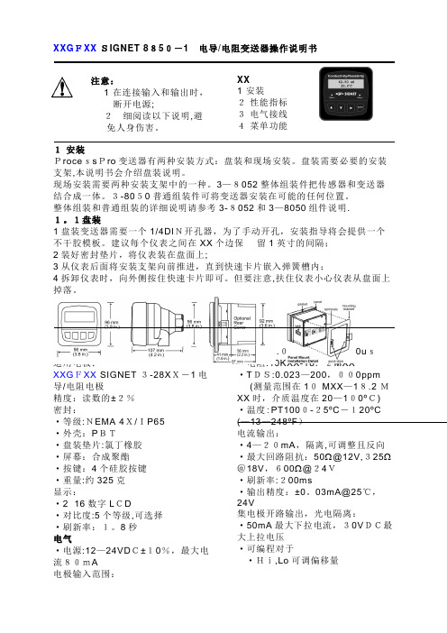
正视(盘装和现场安装)侧视(线场安装) 侧视(盘装)盘装2性能指标普通适用电极:XXGFXX SIGNET 3-28XX-1电导/电阻电极精度:读数的±2%密封:·等级:NEMA 4X/IP65·外壳:PBT·盘装垫片:氯丁橡胶·屏幕:合成聚酯·按键:4个硅胶按键·重量:约325克显示:·2×16数字LCD·对比度:5个等级,可选择·刷新率:1。
8秒电气·电源:12—24VDC±10%,最大电流80mA电极输入范围:·电导:0.055-400,000us·电阻:10KXX-18.2MXX·TDS:0.023—200,000ppm (测量范围在10 MXX—18.2 MXX时,介质温度在20—100ºC) ·温度:PT1000-25ºC-120ºC (—13—248ºF)电流输出:·4—20mA,隔离,可调整且反向·最大回路阻抗:50Ω@12V,325Ω@18V,600Ω@24V·刷新率:200ms·输出精度:±0。
885电气系统技术规格书

SJ017/885-2008 885电气系统技术规格书编制:蔡熙明 2008.5.19 校对:梁帆 2008.5.21审批:梁晓东 2008.5.22根据项目设计总体要求,YC225LC-8(885)电控系统具有以下功能:1、采用16键彩色显示器、MC中型控制器、油门步进电机等组成了挖掘机功率控制系统。
2、根据发动机的负荷的变化,自动调节液压泵吸收的功率,这样,既充分利用发动机的功率,又防止发动机过载熄火。
3、机器具有自动功率模式:H模式(重挖掘动力模式),S模式(节能模式),L(轻载模式)和手动功率模式。
4、具有瞬间增力功能,具有自动怠速控制功能,附件装置控制功能。
5、配置GPS系统,使机器具有定位功能和远程监控功能。
电气系统的组成,可详见885-13电气系统图纸。
本技术规格书,主要包含以下内容:1、彩色显示的监控画面介绍和显示器操作方法。
2、机器的启动、运行、停车、功率控制选择等操作方法。
3、发动机油门系统调整方法。
4、电气系统安装调试的主要技术参数,和检验方法。
1.彩色显示器操作说明本机的监控显示采用“T0412-03235 显示器”。
1.1.彩色显示器面板布局介绍彩色显示器面板(中文界面)布局如图(Fig.1.01)所示。
工作时间计时和时钟(机器状态显示(Fig.1.03)主画面(Fig.1.05)通过按键进行操作菜单的操作,在监控器的主显示区将有不同的信息显示。
注:1、“附件控制”只对应于配装有特定的附件装置有效。
2、“工作模式选择”因各机器的配置不同,控制效果也有差别。
1.3.监控器的操作开启电源,显示器启动后自动进入监控主界面,如图所示(Fig.1.07)。
显示界面显示当前机器的状态信息,(发动机未启动时,有电池电压偏低的报警,有机油压力低报警。
发动机正常启动后,电源电压报警和机油压力低报警标志将消失。
)1.3.1.监控器主菜单:,进入屏幕“主菜单”(Fig.13.08)按或在进行系统初始化设置、数据检查、调试等的操作,将在《机器的调试、检验项目说明》中描述。
电阻电导率表操作说明1

+GF+ SIGNET 8850-1 电导/电阻率表说明书Signet公司的电导/电阻率表在使用前必须被设置和校正(注意:这些已经在本公司被完成)。
阅读仪表随带说明书可以获得更多的安装细节。
一、菜单功能VIEW(观察浏览)菜单:在标准操作期间显示。
●按“▲”或“▼”按钮观察过程参数。
通过按钮的操作,将依次显示:被测介质流量及温度的过程数据、当前输出的电流信号值、最后修改参数的时间。
●10分钟内不按任何按钮,显示界面将回到“VIEW”菜单。
CALIBRATE(校准)菜单:包含了显示设置和输出参数设置功能。
进入此菜单设有密码功能,防止未经授权的私自篡改。
进入CALIBRATE 菜单步骤:●按“ENTER”按钮2秒将显示:CALIBRATE:――――Enter Key Code●依次按“▲”、“▲”、“▲”、“▼”按钮将显示:CALIBRATE:××××Enter Key CodeOPTIONS 菜单:包含了为其它次要的显示或输出调整的设置功能和显示功能。
进入“OPTION”菜单步骤:●按“ENTER”按钮5秒将显示:OPTIONS:――――Enter Key Code●依次按“▲”、“▲”、“▲”、“▼”按钮将显示:OPTIONS:××××Enter Key Code二、菜单提示●当“>”符号显示时,“►”键功能可用来向右卷动,从顶行移动到底行,并且允许进行编辑。
●进入“CALIBRATE”或“OPTIONS”菜单,电导/电阻率变送器将继续测量和1控制输出。
当“►”键被按下时,输入值被抑制在最后测得的过程值。
当传感器没有被连接时,流量变送器将显示“CHECK SENSOR(检查传感器)”。
三、举例说明:(改变修改日期)为了改变日期,第一步进入“CALIBRATE”菜单(按“ENTER”按钮2秒;依次按“▲”、“▲”、“▲”、“▼”按钮),一旦进入“CALIBRATE”菜单,按“▲”按钮1次或依次按“▼”按钮,直至屏幕显示“Last Call:”。
继电器规格书 - RJ-SS-112DM1-S - WRG-Wangrong说明书
PS-002-004012016-7-28客户名/CustomerRELAY SPECIFICATION零件编号/Part Number品名/Product Description RJ-SS-112DM1-SDate Version PS No.继 电 器 规 格 书冯旭强余明亮王凤客户批准/Customer Approval 盖章处/STAMPING AREAR&DSM PD发行批准 / Issued by序号担当00凌剑冰01凌剑冰2016-7-28增加黄山工厂描述变更履历/HISTORY日期变更项目2015-4-13初版1零件清单/PARTS LIST123 4 5 6 7 8 9 10 11 12 13 14 15 16Ver01RG3015010GN6-30 M8XRG301RG301FLAME CLASSUL FILE No.E171666E53664E171666E171666TYPE/TREATMENT型号/处理方式镀镍Vicryst R850Part零件名No.材质MATERIAL镀镍Nickel Plated镀镍Nickel PlatedNickel Plated3UEW 155(F Class)镀锡Base基座骨架Bobbin外壳Case推片CardSolder Coated挂钩Hinge可动弹片C Terminal轭铁Yoke衔铁Armature线材Wire可动接点C ContactM接点M ContactE171666线圈端子Coil Terminal铁芯CoreM端子M TerminalE234867PS-002-004E164502Epoxy胶水UV GlueSealing ResinAg Alloy铜包钢Cu coverd Steel聚氨脂漆包圆铜线Cu Alloy铜合金Polyurethane copper wire环氧树脂Steel铜合金Cu Alloy银合金Ag Alloy银合金Cu Alloy铁LCP铁Steel铁Steel铜合金PBTUV胶PBTPBT2.性能/SPECIFICATIONS2.1驱动部分/COIL SPECIFICATIONS2.1.1额定电压12VDC(在20℃时)Rated Coil Voltage12VDC at 20℃2.1.2额定功率0.45W(在20℃时)Nominal Power0.45W at 20℃2.1.3线圈电阻320Ω±10%(在20℃时)Coil Resistance320Ω±10%(at 20℃)2.1.4额定电流37.5mA±10%(在20℃时)Nominal Current37.5mA±10%(at 20℃)2.1.5吸合电压9VDC以下(在20℃时)Operate Voltage9VDC Max. at 20℃2.1.6释放电压0.6VDC以上(在20℃时)Release Voltage0.6VDC Min. at 20℃2.1.7最大连续施加电压18.6VDC Max. 155%额定电压Max Power18.6VDC Max. 155%of Nominal2.2开关部/CONTACT SPECIFICATION2.2.1开关类型单刀常开型Contact Configuration 1 Form A2.2.2接点规格10 A 250VAC(阻性负载)Contact Rating10 A @250VAC (Resistive)2.2.3接触电阻100mΩ以下, (初期值,DC 24V/1A条件下)Contact Resistance100mΩ Max. @ Initiate, DC 24V/1A500mΩ以下, (寿命试验后,DC 24V/1A条件下)500mΩ Max. @ After Life, DC 24V/1A2.2.4吸合时间20ms 以下(额定电压下)Operate Time20ms Max. @ Rated Voltage2.2.5释放时间10ms 以下(施加额定电压后断开时)Release Time10ms Max. @ Rated Voltage2.2.6最大动作频率300次/分(无负载)Max. Switching Rate300ops./min. (no load).6次/分(额定负载)6ops./min. (Rated load)Ver 01 PS-002-0042.3特性/GENERAL SPECIFICATION2.3.1绝缘电阻1000MΩ以上(500VDC)Insulation Resistance1000MΩ Min@500VDC2.3.2介质耐压1000VAC/分钟(接点间)Dielectric Strength4000VAC/分钟(线圈/接点间)1000VAC@50/60Hz 1 min.(Between Open Contacts)4000VAC@50/60Hz 1 min.(Between Coil and Contacts)2.3.3电气寿命1×10⁵次以上(额定负载,气孔打开)Electrical Life1×105*******************************.2.3.4机械寿命1×10⁶次以上(无负载)Mechanical Life1×106Cycle Min. @no load2.3.5使用环境温度-40~105℃(无凝结时)Temperature-40~105℃ @no condensation2.3.6使用环境湿度20~85%RH(无凝结时)Humidity20~85%RH @no condensation2.3.7抗振动耐久10~55Hz,双振幅 1.5mmVibration Mechanical10 to 55Hz, 1.5mm double amplitude误动作10~55Hz,双振幅2.5mmOperational10 to 55Hz, 2.5mm double amplitude2.3.8抗冲击耐久980m/s2 Min(约100G)Shock Mechanical980m/s2 Min(100G approximately)误动作98m/s2 Min(约10G)Operational98m/s2 Min(10G approximately)2.3.9重量 5.7克Weight 5.7g2.3.10焊锡条件5s@ 260°C (波峰焊)Solder ability5s@ 260°C (wave soldering)2.4端子性能/TERMINAL CHARACTERSITICS2.4.1端子强度5牛/10秒,任意方向静态压力,无异常,但端子弯曲可以Terminals strength5N 10s,Thereshall be no abnormalities.(The curving of the terminal shall be acceptable)2.4.2可焊性260±5℃ 3s,端子头部3mm部分90%以上的面积有锡覆盖Terminal solderbility(无铅焊锡)260±5℃ 3s,In Case of lead lead free solder,90% of the dipped portion shall be solderd.2.4.3耐热性5s @ 260°C,端子头部3mm浸入锡中,无异常发生Soldring Heat Resistance5s @ 260°C,There shall be no abnormalities. (wave soldering)01 Ver PS-002-0042.5安全规格/SAFETY REQUIREMENTS2.5.1UL规格认定(UL & C-UL)档案号:UL(UL & C-UL)File No.:2.5.2CQC标志认证证书编号:CQC Certificate No.:2.5.3TUV规格认定证书号TUV Certificate No.2.5.4产品符合ROHS和REACH要求。
MMBFJ113;中文规格书,Datasheet资料
- TRANSCONDUCTANCE (mmhos) 100
r DS
T A = 25°C TYP V GS(off) = - 2.0 V
100
DS
- DRAIN "ON" RESISTANCE (Ω)
8
- 0.4 V
50
50
6
- 0.6 V
20
g
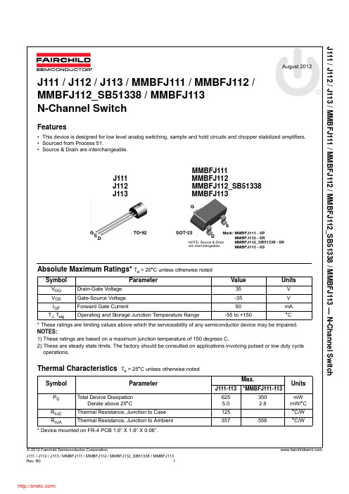
fs I DSS , g fs @ V DS = 15V, V GS = 0 PULSED r DS @ 1.0 mA, V GS = 0 V GS(off) @ V DS = 15V, I D = 1.0 nA _
Features
• This device is designed for low level analog switching, sample and hold circuits and chopper stabilized amplifiers. • Sourced from Process 51. • Source & Drain are interchangeable.
/
J111 / J112 / J113 / MMBFJ111 / MMBFJ112 / MMBFJ112_SB51338 / MMBFJ113 — N-Channel Switch
Electrical Characteristics
Symbol
Off Characteristics
Ta = 25°C unless otherwise noted
Parameter
Test Condition
Min.
-35
Typ.
Max.
Units
V
BV(BR)GSS Gate-Source Breakdown Voltage IG = -1.0A, VDS = 0 IGSS VGS(off) Gate Reverse Current Gate-Source Cutoff Voltage VGS = -15V, VDS = 0 VDS = 5.0V, ID = 1.0A 111 112 MMBFJ112_SB51338 113
8850-1-xrh GF电导仪说明书
1.0000
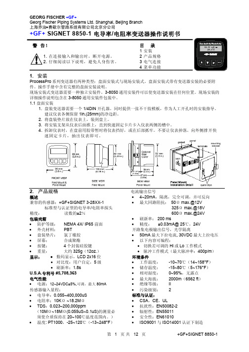
> 入精确的电导常数
Cond Units:
uS
>
PPM Factor:
2.00
>
Set: Temperature >
Set: Conductivity >
Loop Source:
Cond
>
选择测量值单位:uS, mS, kΩ, MΩ, PPM
如果测量值单位设定为 PPM,要在此项中设置固体溶解总量(Total Dissolved Solids)与 uS 的比例。详见本说明书的章节 3。TDS 系数只 能按 PPM 单位设置。
3.3 开路集电极输出信号 当过程变量高于或低于设定值时,开路集电极 输出信号可以用作开关量信号,或根据过程变 量发出比例脉冲信号。
• Low 当过程变量低于设定值时,输出信号被激励。 当流量值高于设定值加切换差时,输出信号复 位。
• 比例脉冲 开路集电极将根据标定菜单(CALIBRATE)中 设定的脉冲率发出 100ms 宽的脉冲信号。
目录
1 安装 2 产品规格 3 电气连接 4 菜单功能
1. 安装
ProcessPro 系列变送器有两种类型:盘面安装式与现场安装式。盘面安装式带有变送器安装的必要附 件。操作手册中含有完整的盘面安装说明。
现场安装式变送器需要一种独立安装件。3-8050 通用安装件可以使变送器安装在任何位置。现场安装的 详细操作说明包含在 3-8050 通用安装件包装中。 1.1 盘面安装
在下面的示例中: • 当测量值小于 5.0 时,输出信号为 0p/m。 • 当测量值等于 7.5 时,输出信号为 50p/m。 • 当测量值达到 10 及以上时,输出信号为
100p/m
BG2A-NFH;中文规格书,Datasheet资料

NOTES:
*Refer to ordering information for included components.
BG2A – Universal Gate Drive Prototype Board
Description: BG2A is a fully isolated two channel gate drive circuit designed for use with dual IGBT modules. The BG2A utilizes Powerex VLA500-01 or VLA502-01 hybrid gate drivers to provide efficient switching of modules rated up to 1400A. The hybrid gate drivers also provide protection against unexpected short circuit conditions using desaturation detection. The VLA500-01 and VLA502-01 hybrid gate drivers have an integrated DC to DC converter with 2500VRMS isolation to provide isolated gate drive power. Control signals are isolated using high speed opto couplers with 15kV/µs common mode noise immunity. The BG2A provides an isolated fault feedback signal if a short circuit condition is detected. Features: Up to 12A Peak Output Current 2500VRMS isolation for control power and signals Standard AMP MTA .100” Connectors Operates from a single 15VDC supply Wide output voltage swing +15V/-8V Compact Size 4” x 2.1” (101mm x 53mm) Applications: BG2A is designed for use with all Powerex NF, A, S and NFH series IGBT modules.
GFSIGNET8850-1电导型变送器说明书讲解
+GF+SIGNET 8850-1 电导型变送器说明书注意目录● 在输入输出接 1. 安装线前切断电源。
2. 技术性能● 认真地根据指 3. 电路连接导以避免个人伤害。
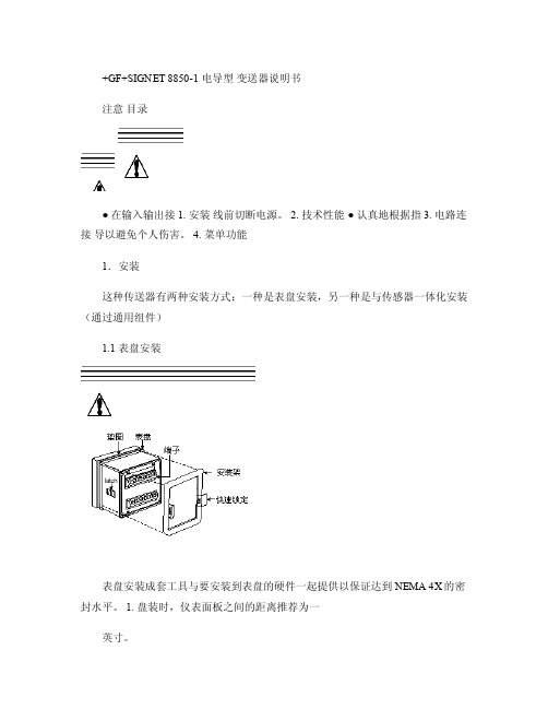
4. 菜单功能1.安装这种传送器有两种安装方式:一种是表盘安装,另一种是与传感器一体化安装(通过通用组件)1.1 表盘安装表盘安装成套工具与要安装到表盘的硬件一起提供以保证达到NEMA 4X的密封水平。
1. 盘装时,仪表面板之间的距离推荐为一英寸。
2. 将垫片装在仪表上,然后装盘。
3. 安装架从仪表背部装入,滑动到锁定位置。
4. 接线到端子。
5. 需要取下仪表时,用带子从前面固定仪表或从背部用手抓住仪表。
不要放开。
压下快速锁定装置,取出仪表。
1. 2通用组件(3-8050)1.安装变送器板。
2.接线到端子。
3.用压旋装置固定,密封出线口。
2.技术指标概述兼容电极:+GF+SIGNET 3-28XX-1 标准系列电导精确度:±2% 读取误差外壳:● 防护等级:NEMA 4X/IP65 ● 壳体材料:PBT● 显示窗:聚氨酯● 键盘:密封4键硅橡胶● 重量:325克显示:● 2*16LCD● 对比度:用户可选择,5级● 刷新周期:1秒环境环境温度:-10到70C(14到158F 存储温度:-15到8OC(5到176F 相对湿度:0到95%,无浓缩标准● CSA,CE,UL● ISO9001标准下制造美国专利号#5,708,363 电气特性传感器输入范围:● 传导率:0。
055到400,000微秒● 阻抗:10-18.26千欧● TDS :0.023-2000,000PPM电气特性传感器输入范围:● 传导率:0。
055到400,000微秒● 阻抗:10-18.26千欧● TDS :0.023-2000,000PPM ● 温度:PT1000, -25到120C (-13-248F )电流输出:● 4到20mA 隔离,完全可调和可逆输出● 电源:12到24VDC ±5% 稳压● 最大闭环阻抗:50欧姆 MAX @12V, 325欧姆 MAX @18V, 600欧姆MAX @ 24V ● 刷新周期:0.5秒● 精确度:±0.03mA@ 25C,24V集电极开路输出:高,低,可编程脉冲● 集电极,隔离,50mA 吸入或源电流,30VDC max拉入电压● 滞后:用户可调3.电气连接注意:在拆除电线前没有完全打开端子接线夹可能导致仪表的永久损坏。
BD1631J50100AHF;中文规格书,Datasheet资料
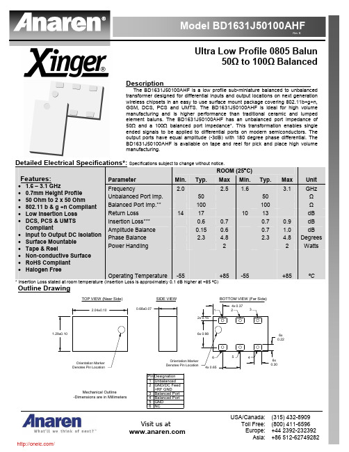
Rev BUltra Low Profile 0805 Balun50Ω to 100Ω BalancedDescriptionThe BD1631J50100AHF is a low profile sub-miniature balanced to unbalanced transformer designed for differential inputs and output locations on next generation wireless chipsets in an easy to use surface mount package covering 802.11b+g+n, GSM, DCS, PCS and UMTS. The BD1631J50100AHF is ideal for high volume manufacturing and is higher performance than traditional ceramic and lumped element baluns. The BD1631J50100AHF has an unbalanced port impedance of 50Ω and a 100Ω balanced port impedance*. This transformation enables single ended signals to be applied to differential ports on modern semiconductors. The output ports have equal amplitude (-3dB) with 180 degree phase differential. The BD1631J50100AHF is available on tape and reel for pick and place high volume manufacturing.Detailed Electrical Specifications*: Specifications subject to change without notice.ROOM (25°C)Parameter Min. Typ. Max Min. Typ.Max Unit Frequency2.0 2.5 1.63.1GHz Unbalanced Port Imp. 50 50 Ω Balanced Port Imp.** 100 100 Ω Return Loss 14 17 10 13 dBInsertion Loss*** 0.6 0.7 0.7 0.9 dB Amplitude Balance 0.15 0.6 0.7 1.0 dB Phase Balance 2.3 4.82.3 4.8Degrees Power Handling 22WattsFeatures: • 1.6 – 3.1 GHz• 0.7mm Height Profile • 50 Ohm to 2 x 50 Ohm • 802.11 b & g +n Compliant • Low Insertion Loss • DCS, PCS & UMTS Compliant• Input to Output DC Isolation • Surface Mountable • Tape & Reel• Non-conductive Surface • RoHS Compliant •Halogen FreeOperating Temperature -55 +85 -55 +85 ºC* Insertion Loss stated at room temperature (Insertion Loss is approximately 0.1 dB higher at +85 ºC)Outline DrawingMechanical Outline-Dimensions are in Millimeters2.04±0.100.68±0.076x 0.22Orientation Marker Denotes Pin LocationTOP VIEW (Near Side)SIDE VIEWBOTTOM VIEW (Far Side)5 4 2 16 3 PinBalanced Port GNDNCBalanced PortGND/DC Feed UnbalancedDesignation+RF GNDInsertion Loss2500300035004000450050005500600065007000750080008500Frequency [MHz]Phase BalanceRev BMounting Configuration:In order for Xinger surface mount components to work optimally, the proper impedance transmission lines must be used to connect to the RF ports. If this condition is not satisfied, insertion loss, Isolation and VSWR may not meet published specifications.All of the Xinger components are constructed from organic PTFE based composites which possess excellent electrical and mechanical stability. Xinger components are compliant to a variety of ROHS and Green standards and ready for Pb-free soldering processes. Pads are Gold plated with a Nickel barrier.An example of the PCB footprint used in the testing of these parts is shown below. An example of a DC-biased footprint is also shown below. In specific designs, the transmission line widths need to be adjusted to the unique dielectric coefficients and thicknesses as well as varying pick and place equipment tolerances.No Bias Footprintlines holes to groundCircuit Pattern Footprint Pad (s)Solder ResistMounting FootprintDimensions are in MillimetersTOP DOWNDC Bias Footprintlines Mounting FootprintDimensions are in Millimeters TOP DOWNRev BPackaging and Ordering InformationParts are available in reel and are packaged per EIA 481-2. Parts are oriented in tape and reel as shown below. Minimum order quantities are 4000 per reel. See Model Numbers below for further ordering information .分销商库存信息: ANARENBD1631J50100AHF。
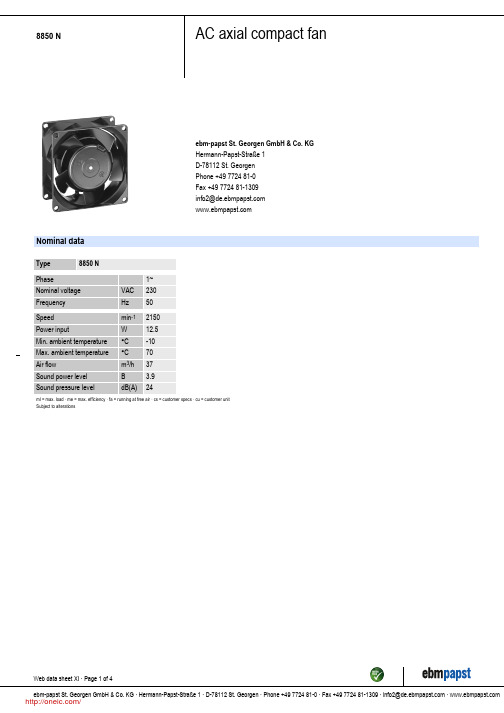
8850N;中文规格书,Datasheet资料
/
8850 N
AC axial compact fan
Product drawing
Web data sheet XI · Page 3 of 4 ebm-papst St. Georgen GmbH & Co. KG · Hermann-Papst-Straße 1 · D-78112 St. Georgen · Phone +49 7724 81-0 · Fax +49 7724 81-1309 · info2@ ·
ml = max. load · me = max. efficiency · fa = running at free air · cs = customer specs · cu = customer unit Subject to alterations
Web data sheet XI · Page 1 of 4 ebm-papst St. Georgen GmbH & Co. KG · Hermann-Papst-Straße 1 · D-78112 St. Georgen · Phone +49 7724 81-0 · Fax +49 7724 81-1309 · info2@ ·
/
分销商库存信息:
EBM-PAPST 8850N
Web data sheet XI · Page 2 of 4 ebm-papst St. Georgen GmbH & Co. KG · Hermann-Papst-Straße 1 · D-78112 St. Georgen · Phone +49 7724 81-0 · Fax +49 7724 81-1309 · AC axial compact fan
FGA40N65SMD;中文规格书,Datasheet资料
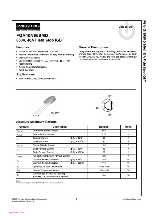
G CE
TO-3PN
Absolute Maximum Ratings
Symbol
VCES VGES IC
ICM (1) IF
IFM (1) PD
TJ Tstg TL
Description
Collector to Emitter Voltage
Gate to Emitter Voltage
Collector Current Collector Current
DTJ ICES IGES
Collector to Emitter Breakdown Voltage VGE = 0V, IC = 250mA
Temperature Coefficient of Breakdown
Voltage
VGE = 0V, IC = 250mA
Collector Cut-Off Current G-E Leakage Current
IC = 40A, VGE = 15V
IC = 40A, VGE = 15V, TC = 175oC
Dynamic Characteristics
Cies Coes Cres
Input Capacitance Output Capacitance Reverse Transfer Capacitance
Typical Performance Characteristics
Figure 1. Typical Output Characteristics
120
o
TC = 25 C
20V 12V 15V
100
10V
Collector Current, IC [A]
80
60
744710215;中文规格书,Datasheet资料

5.1 5.0 4.02012-06-272012-05-022009-06-30SStSStRStSStCZWürth Elektronik eiSos GmbH & Co. KGEMC & Inductive SolutionsMax-Eyth-Str. 174638 WaldenburgGermanyTel. +49 (0) 79 42 945 - 0A Dimensions: [mm]F Typical Impedance Characteristics:H4: Classification Wave Soldering Profile:H5: Classification Wave ProfileProfile FeaturePreheat- Temperature Min (T smin )- Temperature Typical (T stypical ) - Temperature Max (T smax ) - Time (t s ) from (T smin to T smax )Δ preheat to max Temperature Peak temperature (T p )Time of actual peak temperature (t p )Ramp-down rate - Min - Typical - MaxTime 25°C to 25°C Pb-Free Assembly 100°C 120°C 130°C 70 seconds 150°C max.250°C - 260°C max. 10 secondsmax. 5 second each wave ~ 2 K/s ~ 3.5 K/s ~ 5 K/s 4 minutesSn-Pb Assembly 100°C 120°C 130°C 70 seconds 150°C max.235°C - 260°C max. 10 secondsmax. 5 second each wave ~ 2 K/s ~ 3.5 K/s ~ 5 K/s 4 minutesrefer to EN 61760-1:2006H Soldering Specifications:I Cautions and Warnings:The following conditions apply to all goods within the product series of WE-SDof Würth Elektronik eiSos GmbH & Co. KG:General:All recommendations according to the general technical specifications of the data-sheet have to be complied with.The disposal and operation of the product within ambient conditions which probably alloy or harm the wire isolation has to be avoided.If the product is potted in customer applications, the potting material might shrink during and after hardening. Accordingly to this the product is exposed to the pressure of the potting material with the effect that the core, wire and termination is possibly damaged by this pressure and so the electrical as well as the mechanical characteristics are endanger to be affected. After the potting material is cured, the core, wire and termination of the product have to be checked if any reduced electrical or mechanical functions or destructions have occurred.The responsibility for the applicability of customer specific products and use in a particular customer design is always within the authority of the customer. All technical specifications for standard products do also apply for customer specific products.Washing varnish agent that is used during the production to clean the application might damage or change the characteristics of the wire in-sulation, the marking or the plating. The washing varnish agent could have a negative effect on the long turn function of the product.Direct mechanical impact to the product shall be prevented as the ferrite material of the core could flake or in the worst case it could break. Product specific:Follow all instructions mentioned in the datasheet, especially:•The solder profile has to be complied with according to the technical wave soldering specification, otherwise no warranty will be sustai-ned.•All products are supposed to be used before the end of the period of 12 months based on the product date-code, if not a 100% solderabi-lity can´t be warranted.•Violation of the technical product specifications such as exceeding the nominal rated current will result in the loss of warranty.1. General Customer ResponsibilitySome goods within the product range of Würth Elektronik eiSos GmbH & Co. KG contain statements regarding general suitability for certain application areas. These statements about suitability are based on our knowledge and experience of typical requirements concerning the are-as, serve as general guidance and cannot be estimated as binding statements about the suitability for a customer application. The responsibi-lity for the applicability and use in a particular customer design is always solely within the authority of the customer. Due to this fact it is up to the customer to evaluate, where appropriate to investigate and decide whether the device with the specific product characteristics described in the product specification is valid and suitable for the respective customer application or not.2. Customer Responsibility related to Specific, in particular Safety-Relevant ApplicationsIt has to be clearly pointed out that the possibility of a malfunction of electronic components or failure before the end of the usual lifetime can-not be completely eliminated in the current state of the art, even if the products are operated within the range of the specifications.In certain customer applications requiring a very high level of safety and especially in customer applications in which the malfunction or failure of an electronic component could endanger human life or health it must be ensured by most advanced technological aid of suitable design of the customer application that no injury or damage is caused to third parties in the event of malfunction or failure of an electronic component.3. Best Care and AttentionAny product-specific notes, warnings and cautions must be strictly observed.4. Customer Support for Product SpecificationsSome products within the product range may contain substances which are subject to restrictions in certain jurisdictions in order to serve spe-cific technical requirements. Necessary information is available on request. In this case the field sales engineer or the internal sales person in charge should be contacted who will be happy to support in this matter.5. Product R&DDue to constant product improvement product specifications may change from time to time. As a standard reporting procedure of the Product Change Notification (PCN) according to the JEDEC-Standard inform about minor and major changes. In case of further queries regarding the PCN, the field sales engineer or the internal sales person in charge should be contacted. The basic responsibility of the customer as per Secti-on 1 and 2 remains unaffected.6. Product Life CycleDue to technical progress and economical evaluation we also reserve the right to discontinue production and delivery of products. As a stan-dard reporting procedure of the Product Termination Notification (PTN) according to the JEDEC-Standard we will inform at an early stage about inevitable product discontinuance. According to this we cannot guarantee that all products within our product range will always be available. Therefore it needs to be verified with the field sales engineer or the internal sales person in charge about the current product availability ex-pectancy before or when the product for application design-in disposal is considered.The approach named above does not apply in the case of individual agreements deviating from the foregoing for customer-specific products.7. Property RightsAll the rights for contractual products produced by Würth Elektronik eiSos GmbH & Co. KG on the basis of ideas, development contracts as well as models or templates that are subject to copyright, patent or commercial protection supplied to the customer will remain with Würth Elektronik eiSos GmbH & Co. KG.8. General Terms and ConditionsUnless otherwise agreed in individual contracts, all orders are subject to the current version of the “General Terms and Conditions of Würth Elektronik eiSos Group”, last version available at .J Important Notes:The following conditions apply to all goods within the product range of Würth Elektronik eiSos GmbH & Co. KG:分销商库存信息: WURTH-ELECTRONICS 744710215。
SPAN-IGM-A1 Datasheet(中文)
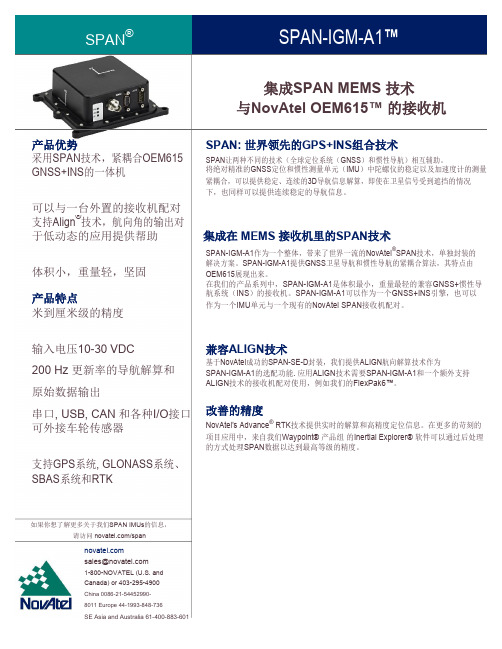
集成SPAN MEMS 技术与NovAtel OEM615™ 的接收机产品优势SPAN: 世界领先的GPS+INS组合技术采用SPAN技术,紧耦合OEM615 SPAN让两种不同的技术(全球定位系统(GNSS)和惯性导航)相互辅助。
GNSS+INS的一体机将绝对精准的GNSS定位和惯性测量单元(IMU)中陀螺仪的稳定以及加速度计的测量紧耦合,可以提供稳定、连续的3D导航信息解算,即使在卫星信号受到遮挡的情况下,也同样可以提供连续稳定的导航信息。
可以与一台外置的接收机配对支持Align®技术,航向角的输出对于低动态的应用提供帮助集成在 MEMS 接收机里的SPAN技术SPAN-IGM-A1作为一个整体,带来了世界一流的NovAtel®SPAN技术,单独封装的体积小,重量轻,坚固解决方案。
SPAN-IGM-A1提供GNSS卫星导航和惯性导航的紧耦合算法,其特点由OEM615展现出来。
产品特点在我们的产品系列中,SPAN-IGM-A1是体积最小,重量最轻的兼容GNSS+惯性导航系统(INS)的接收机。
SPAN-IGM-A1可以作为一个GNSS+INS引擎,也可以作为一个IMU单元与一个现有的NovAtel SPAN接收机配对。
米到厘米级的精度输入电压10-30 VDC兼容ALIGN技术200 Hz 更新率的导航解算和基于NovAtel成功的SPAN-SE-D封装,我们提供ALIGN航向解算技术作为SPAN-IGM-A1的选配功能. 应用ALIGN技术需要SPAN-IGM-A1和一个额外支持原始数据输出ALIGN技术的接收机配对使用,例如我们的FlexPak6™。
串口, USB, CAN 和各种I/O接口改善的精度NovAtel's Advance® RTK技术提供实时的解算和高精度定位信息。
在更多的苛刻的可外接车轮传感器项目应用中,来自我们Waypoint® 产品组的Inertial Explorer® 软件可以通过后处理的方式处理SPAN数据以达到最高等级的精度。
2.4GHz MID SMT 天线产品规格表说明书

CREATED / REVISED BY: Kang Cheng
CHECKED BY: Horace Ma
APPROVED BY: Welson Tan
TEMPLATE FILENAME: PRODUCT_SPEC[SIZE_A4](V.1).DOC
PRODUCT SPECIFICATION
TEMPLATE FILENAME: PRODUCT_SPEC[SIZE_A4](V.1).DOC
PRODUCT SPECIFICATION
3.0 APPLICABLE DOCUMENTS
DOCUMENT Sale Drawing (SD) Application Guide (AS) Packing Drawing (PK)
REVISION: ECR/ECN INFORMATION: TITLE:
G1
EC No: 763980 DATE: 2023/02/15
2.4GHZ MID SMT Antenna Product Specification
SHEET No.
1 of 11
DOCUMENT NUMBER:
PS-479480001
PRODUCT SPECIFICATION
TITLE
2.4GHZ MID SMT ANTENNA
TABLE OF CONTENTS
1.0 SCOPE 2.0 PRODUCT DESCRIPTION 3.0 APPLICABLE DOCUMENTS 4.0 GENERAL SPECIFICATION 5.0 ANTENNA SPECIFICATION 6.0 MECHANICAL REQUIREMENTS 7.0 ENVIRONMENTAL SPECIFICATION 8.0 RECOMMENDED REFLOW CONDITION 9.0 RECOMMENDED FOOTPRINT ON PCB FOR SOLDERING 10.0 PACKING 11.0 OTHER MOLEX ANTENNA PRODUCTS 12.0 CHANGED HISTORY
78M6612-EVM-1;中文规格书,Datasheet资料

Simplifying System Integration TM78M6612 AC-PMON Evaluation BoardUser ManualFebruary 1, 2010Rev. 1.1UM_6612_01378M6612 AC-PMON Evaluation Board User Manual UM_6612_013 © 2010 Teridian Semiconductor Corporation. All rights reserved.Teridian Semiconductor Corporation is a registered trademark of Teridian Semiconductor Corporation. Simplifying System Integration is a trademark of Teridian Semiconductor Corporation.Microsoft, Windows, Vista, and Excel are registered trademarks of Microsoft Corporation.CA51 is a trademark of Keil, An ARM® Company.Signum Systems is a trademark of Signum Systems Corp.LabVIEW, NI and NI-VISA are trademarks of National Instruments.All other trademarks are the property of their respective owners.Teridian Semiconductor Corporation makes no warranty for the use of its products, other than expressly contained in the Company’s warranty detailed in the Teridian Semiconductor Corporation standard Terms and Conditions. The company assumes no responsibility for any errors which may appear in this document, reserves the right to change devices or specifications detailed herein at any time without notice and does not make any commitment to update the information contained herein. Accordingly, the reader is cautioned to verify that this document is current by comparing it to the latest version on or by checking with your sales representative.Teridian Semiconductor Corp., 6440 Oak Canyon, Suite 100, Irvine, CA 92618TEL (714) 508-8800, FAX (714) 508-8877, UM_6612_013 78M6612 AC-PMON Evaluation Board User ManualTable of Contents1Introduction (5)1.1Package Contents (5)1.2System Requirements (5)1.3Safety and ESD Notes (6)1.4Firmware Demo Code Introduction (6)1.5Testing the AC-PMON Evaluation Board Prior to Shipping (6)2Installation (7)2.1USB Driver Installation (7)2.2Confirm COM Port Mapping (8)2.3Basic Connection Setup (9)2.4Verify Serial Connection to the PC (11)2.5NI RunTime Installation (13)2.6Install LabWindows™ XP Pro Update (16)3Operating the Dashboard GUI (19)3.1Port Selection (19)3.2Creating a Measurement Data Log File (20)3.3Selecting the Power Display Parameter (20)3.4Selecting the Display Scales (21)3.5Resetting the Min and Max Indicators to Their Current Values (21)3.6Begin Tracking Minimum and Maximum Conditions (22)3.7Selecting Outlet1 (22)3.8Selecting Wide Band or Narrow Band Measurement (23)3.9Selecting the Sample Interval (23)3.10Alarm Status (23)3.11Neutral Voltage Alarm (24)3.12Line Frequency (24)3.13Accumulated Energy Usage and Expense Tracking (25)3.14Displaying Narrowband and Wideband Values Simultaneously (25)3.15Using the Parameter Graph (26)3.16Setting Alarm Status Thresholds (26)3.17Relay Configuration Controls (27)3.18Log File Import to Excel® (28)4Schematics, Bill of Materials and PCB Layouts (31)4.178M6612 AC-PMON Evaluation Board Schematics (31)4.278M6612 AC-PMON Evaluation Board Bill of Materials (33)4.378M6612 AC-PMON Evaluation Board PCB Layouts (34)4.4USB Daughter Board Schematics (35)4.5USB Daughter Board Bill of Materials (35)5Ordering Information (36)6Included Documentation (36)7Contact Information (36)Revision History (36)78M6612 AC-PMON Evaluation Board User Manual UM_6612_013 FiguresFigure 1: AC-PMON Connections (9)Figure 2: AC-PMON Application Diagram (9)Figure 3: 78M6612 Evaluation Board Electrical Schematic (1 of 2) (31)Figure 4: 78M6612 Evaluation Board Electrical Schematic (2 of 2) (32)Figure 5: 78M6612 Evaluation Board PCB Top View (34)Figure 6: 78M6612 Evaluation Board PCB Top Copper (34)Figure 7: USB Daughter Board Electrical Schematic (35)TableTable 1: COM Port Setup Parameters (11)Table 2: 78M6612 Evaluation Board Bill of Materials (33)Table 3: USB Daughter Board Bill of Materials (35)UM_6612_013 78M6612 AC-PMON Evaluation Board User Manual 1 IntroductionThe Teridian Semiconductor Corporation (TSC) 78M6612 AC-PMON Evaluation Board is an electrical measurement unit for performing measurements from a single electrical outlet. It incorporates the TSC 78M6612 single-phase, dual-outlet, power and energy measurement IC. The AC-PMON Evaluation Board is connected to PC through a USB cable such as one provided in the demo kit package. The Evaluation Board demonstrates the capability of the 78M6612 energy meter controller chip for measurement accuracy and overall system use.The board is pre-programmed with demo firmware (file name6612_OMU_S2_URT_V1_13.hex) in the flash memory of the78M6612 IC that allows evaluation of the capability of the IC.Included with the AC-PMON is a Windows based Graphical UserInterface (GUI) for simplified access to the following measurementdata and controls:•Power, current, voltage and power factor indicator dials•Adjustable display scales•Minimum and peak parameter tracking•Selectable strip chart display format•Narrow-band versus Wide-band measurement•Selectable sample size averaging•Accumulated energy usage and expense tracking•Line frequency•Alarm indicators•Programmable Alarm thresholds•Data log to fileAlternatively, the user can directly query the device with the command set using HyperTerminal and the provided 6612_OMU_S2_URT_V1_13 Firmware Description Document.1.1 Package ContentsThe 78M6612 AC-PMON Evaluation Board Demo Kit includes:•78M6612 AC-PMON Evaluation Board•USB Daughter Board•USB Cable Assembly USB A-B 28/24 1.8M (Tyco/Amp 1487588-3)•CD with OMU Software and Documentation1.2 System RequirementsThe 78M6612 AC-PMON Evaluation Board requires use of a PC with the following features:•PC (1 GHz, 1 GB) with Microsoft® Windows XP or Win2000, equipped with USB port.•Minimum 1024 x 768 video display resolution.78M6612 AC-PMON Evaluation Board User Manual UM_6612_0131.3 Safety and ESD NotesEXERCISE CAUTION WHEN LIVE AC VOLTAGES ARE PRESENT!Standard ESD precautions must be taken when handling electronic equipment. TheAC-PMON contains ESD protected interfaces.Do not connect test equipment, ICE emulators or external development boards directly to the OMU-RF hardware. Damage to the OMU1-S-RF and external equipment will occur due to the78M6612’s “high side” reference topology. The 78M6612’s V3P3 (i.e. “high side”) is connected directly to Neutral (Earth Ground) creating a ground reference disparity with any properly grounded external equipment.1.4 Firmware Demo Code IntroductionThe Firmware Demo Code provides the following features:•Basic energy measurement data such as Watts, Volts, current, VAR, VA, phase angle, power factor, accumulated energy, frequency, date/time, and various alarm statuses.•Control of alarm thresholds, calibration coefficients, temperature compensation, etc.There are two means to facilitate performance evaluation between the user at the PC host and the firmware code in the board:•The Graphical User Interface (GUI). This document describes the installation and use of the Windows based GUI.•The Command Line Interface (CLI) via HyperTerminal or comparable terminal emulator on a different operating system. For information about the CLI, see the 6612_OMU_S2_URT_V1_13 Firmware Description Document.The AC-PMON is shipped with Demo Code Revision 1.13 or later loaded in the 78M6612 chip and included on the CD. The code revision can be verified by entering the command >i via the command line interface. Firmware for the Demo Unit can be updated using either the Teridian TFP1 or an in-circuit emulator such as the Signum Systems™ ADM-51 (/Signum.htm).The board components and firmware settings are designed to operate with the following nominal AC electrical ranges:Voltage Current Line Frequency110-240 VAC 10 mA – 20A 46-64 Hz1.5 Testing the AC-PMON Evaluation Board Prior to ShippingBefore every AC-PMON Evaluation Board is shipped, the following procedures have been performed at the factory:•Full Calibration – Precise energy source equipment is used to calibrate the current and voltage. The temperature is also calibrated at the same time.•Accuracy Test – This “bench” level test ensures the energy accuracy is within +/-0.5%.UM_6612_013 78M6612 AC-PMON Evaluation Board User Manual 2 Installation2.1 USB Driver InstallationThis evaluation kit includes an optically isolated USB adaptor board for serial communications with a PC. The FTDI USB controller IC FT232RL performs the USB functions. The FTDI Windows driver presents a virtual COM port for enabling serial communications. Control of the AC-PMON module can be managed using either a terminal emulation program or using the supplied Windows Dashboard GUI. The FTDI Windows driver is a certified driver for Windows 2000 and XP.1. Upon attaching the AC-PMON to the PC, the Found New Hardware Wizard automatically launchesand installs the appropriate driver files. If your PC does not find the FTDI driver files on its local hard disk drive, locate and reference the FTDI USB Driver and Utilities subdirectory on the CD. TheFT232RL controller is powered from the USB cable and is active even when no AC power is applied to the AC-PMON.Notes: If an older FTDI driver has been previously installed, it is recommended to remove the older version before installing this newer FTDI driver. Execute the ftdiClean.exe utility from the FTDI USB Driver and Utilities subdirectory.For FTDI driver support on other operating systems, please check FTDI’s website at(/FTDrivers.htm).78M6612 AC-PMON Evaluation Board User Manual UM_6612_0132.2 Confirm COM Port Mapping1. Launch the Control Panel and click on the System icon.2. The System Properties screen appears. Click on the Hardware tab. Click on Device Manager .Under Ports (COM & LPT), look for the USB Serial Port assignment.3. Take note of the COM port assignment for the USB Serial Port.UM_6612_013 78M6612 AC-PMON Evaluation Board User Manual2.3 Basic Connection SetupFigure 1 shows the basic connections of the 78M6612 AC-PMON Evaluation Board with the external equipment. The AC-PMON is powered through the USB cable. This same USB cable provides the communications link between the host PC and the AC-PMON.The AC-PMON has two IEC 60320 connectors, one male and one female. The male connector is for inlet and the female connector is for outlet. The male connector is connected to a power chord from a wall outlet. The female connector connects to the load to be measured .Figure 1: AC-PMON ConnectionsFigure 2: AC-PMON Application DiagramConnect to the Load to be MeasuredConnect to IEC Power PlugConnect the USB Port to the Host PCwith GUI78M6612 AC-PMON Evaluation Board User Manual UM_6612_013 The USB board connects to the AC-PMON Evaluation Board as shown below.The red and green wires of the USB board connect to J7.1 and J7.4 of the AC-PMON Evaluation Board, respectively, and are the wires that carry the 5VDC and GND to the AC-PMON Evaluation Board.分销商库存信息: MAXIM78M6612-EVM-1。
+GF+-SIGNET8850电导率变送器手册
+GF+ SIGNET8850-1 电导率/电阻率变送器警告:●接入输入输出线前请将电源断开。
●谨遵说明,以免人身伤害。
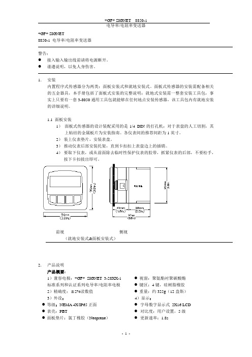
1.安装内置程序式传感器分为两类:面板安装式和就地安装式。
面板式传感器的安装需配备相关的五金器具,本手册包括了面板式安装的完整说明;就地式安装需一整套安装工具包,事实上只要有一套3-8050通用工具包就能够在任何地点安装传感器,该工具包内有就地安装的详细说明。
1.1 面板安装1)面板式传感器的设计装配采用的是1/4 DIN的打孔机;对于表盘的人工切割,其上粘结的金属板片为安装指南。
各仪表间的推荐间距为1英寸。
2)装上仪表垫片,安装表盘。
3)推动仪表后部安装托架,直到卡扣扣上表盘边上的插销。
4)要取下仪表,或从前面除去临时性保护仪表的胶带,抓紧仪表的后部,不要松手,按下卡扣拔出即可。
前视侧视(就地安装式&面板安装式)2.产品说明产品概要:1)兼容电极:+GF+ SIGNET 3-28XX-1标准系列和认证系列电导率/电阻率电极2)精确度: 2%读数值3)外设:●等级:NEMA 4X/IP65正面●表壳:PBT●面板垫片:氯丁橡胶(Neoprene)●视窗:聚氨酯衬聚碳酸酯●键区:4键,硅树脂橡胶●重量:约325g(12盎斯)4)显示:●字母数字显示式2X16 LCD ●对比度:用户设置,5级●更新速率:1.8s电气参数:●电源:12-24VDC 10%,可调,最大80mA传感器输入范围:●电导率:0.01 —400000 S/cm●电阻率:10K cm — 100M cmTDS:0.023 — 200000 PPM (可调 S/PPM)●温度:PT 1000,-25 — 120℃(-13 — 248℉);量程超过10M (低于0.1 S)时温度范围必须在20 — 100℃内●被动,独立,完全可调可逆转式4 — 20mA信号能各自输出电导率和温度●最大回路阻抗:最大50 @12V最大325 @18V最大600 @24V●更新速率:200ms●精确度: 0.03mA@25℃,24V开放式收集器输出,独立显示●最大50mA的衰减,最大上升到的电压30VDC●可编程项:●高低可调磁滞●脉冲运行(最大速率:400脉冲/分钟)环境条件:●运行温度:-10 —70℃(14 — 158℉)●存放温度:-15 —80℃(5 — 176℉)●相对湿度:0 — 95%,无冷凝●最大海拔:2000m(6562英尺)●绝缘类别:II●污染等级:2标准和认证:●CSA,CE,UL●免疫性:EN50082-2●放射性:EN55011,Class-B●在ISO9001和ISO14001标准下生产制造U.S.A.专利号#57083633. 电气接线警告:卸线前没有完全开启终端接线夹可能会永久性损坏设备。
8850电导变送器
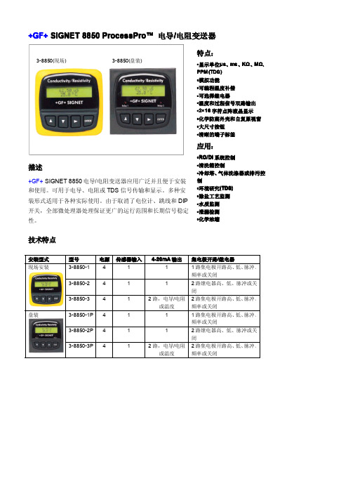
+GF+SIGNET8850ProcessProProcessPro™™电导/电阻变送器描述+GF+SIGNET8850电导/电阻变送器应用广泛并且便于安装和使用。
可用于电导、电阻或TDS信号传输和显示。
多种安装形式适用于各种实际使用。
由于取消了电位计、跳线和DIP 开关,全部微处理器处理保证更广的运行范围和长期信号稳定性。
技术特点安装型式型号电源传感器输入4-20mA输出集电极开路/继电器现场安装3-8850-14111路集电极开路高、低、脉冲、频率或关闭3-8850-24112路继电器高、低、脉冲或关闭3-8850-3412路,电导/电阻或温度2路集电极开路高、低、脉冲、频率或关闭盘装3-8850-1P4111路集电极开路高、低、脉冲、频率或关闭3-8850-2P4112路继电器高、低、脉冲或关闭3-8850-3P412路,电导/电阻或温度2路集电极开路高、低、脉冲、频率或关闭3-8850(现场)3-8850(盘装)尺寸盘装现场安装安装变送器可以盘装或现场安装。
选择通用安装组件(3-8050)将变送器安装在传感器附近的位置上。
1盘装2通用安装所有盘装变送器(3-8850-XP)包括一个支架和垫圈,满足NEMA4X防水等级。
盘装变送器需要标准的1/4DIN盘面开孔。
通用安装组件(3-8050)可以单独定货,它包括一个导线基座,锁定环和将变送器安装在管道、墙壁上或其他固定设备表面上的适配器。
电导/电阻变送器3-8850-XP包括支架和垫圈电导/电阻传感器通用适配器3-8050包括锁定环导线基座通用适配器(固定于管道、墙壁)电导/电阻传感器3-8050组件背后端子视图技术参数普通指标适用电极:+GF+SIGNET3-28XX-X标准和NIST 认证的电导和电阻电极精度:读数的±2%密封:·等级:前面板NEMA4X/IP65·外壳:PBT·盘装垫圈:氯丁橡胶·屏幕:合成聚酯·按键:4个硅胶按键·重量:约325克显示:·2×16数字LCD·对比度:5个等级,可选择环境运行温度:-10ºC-70ºC(14-158ºF)保存温度:-15ºC-80ºC(5-176ºF)相对湿度:0-95%,无露点标准和认证·CSA,CE,UL·ISO9001认证电气电源:·12-24VDC±10%,可调整,(-1)最大21mA,(-2)最大220mA,(-3)最大60mA传感器输入范围:·电导:0.055-400000μs·电阻:10KΩ-18.2MΩ·TDS:0.023-200000ppm·温度:PT1000,-25-120ºC(-13-248ºF)电流输出:·4-20mA,隔离,可调整且可反向·最大回路阻抗:50Ω@12V,325Ω@18V,600Ω@24V·刷新速度:0.5s·精度:±0.03mA@25ºC,24V继电器输出:·机械SPDT接点:高、低、脉冲、关闭·最大额定电压:5A@30VDC,5A@250VAC阻性负载·滞后量:可调整·最大400脉冲/分钟集电极开路输出:高、低、脉冲、关闭·集电极开路,光电隔离,50mA最大下拉电流,30VDC最大上拉电压·最大400脉冲/分钟3.端子8850-2订货资料型号编码描述3-8850-1159000228电导/电阻变送器,现场安装3-8850-1P159000229电导/电阻变送器,盘装3-8850-2159000230电导/电阻变送器,现场安装,继电器输出3-8850-2P159000231电导/电阻变送器,盘装,继电器输出3-8850-3159000232电导/电阻变送器,现场安装,单路输入/双路输出3-8850-3P159000233电导/电阻变送器,盘装,单路输入/双路输出附件型号编码描述3-8050159000184通用安装组件3-8050.395159000186变送器NEMA4X密封盖3-80521590001883/4”整体安装件3-8050.396159000617RC滤波器组件(用于继电器输出)3-0000.596159000641牢固的墙装支架3-8050.392159000640200型新式适配器工程规格书:·变送器应该符合CE、CSA&UL标准。
TC Electronic BG250-112 BG250-115 BG250-210使用说明书

■ This device should be installed near the socket outlet and disconnection of the device should be easily accessible.
the use of different types of line cord and attachment plugs. ■ ChecБайду номын сангаас the voltage in your area and use the correct type. Please refer to the following table:
cordance with the manufacturer’s instructions. 8. Do not install near heat sources such as radiators,
heat registers, stoves, or other apparatus (including amplifiers) that produce heat. 9. Do not defeat the safety purpose of the polarized or grounding-type plug. A polarized plug has two blades with one wider than the other. A grounding type plug has two blades and a third grounding prong. The wide blade or the third prong are
ABB火检

2.1.1 2.1.2 2.1.3 2.1.4 检测器安装 ................................ ................................ ................................ .......................... 火焰检测器 ................................ ................................ ................................ .......................... 接插件/电缆 ................................ ................................ ................................ ......................... 火焰分析单元 ................................ ................................ ................................ ....................... 10 11 11 11
uvisorfau810使用手册uvisor?火焰检测系统使用手册火焰分析单元fau810使用手册pdfcreatedwithfineprintpdffactorytrialversionwwwpdffactorycomuvisorfau810使用手册299目录1导言
- 1、下载文档前请自行甄别文档内容的完整性,平台不提供额外的编辑、内容补充、找答案等附加服务。
- 2、"仅部分预览"的文档,不可在线预览部分如存在完整性等问题,可反馈申请退款(可完整预览的文档不适用该条件!)。
- 3、如文档侵犯您的权益,请联系客服反馈,我们会尽快为您处理(人工客服工作时间:9:00-18:30)。
mm 20.8
4.15 0.51 0.25 27.2 2.54 13.75 2.54 5.08 12.7 8.8 3.85 0.38
2.4 38.1 25.4 10.2 4.2 44.75 8.2 6-32 0.25 0.7 44.25 7.8 UNC
OUTLINE VERSION SOT115D
REFERENCES IEC JEDEC JEITA
2. The product status of device(s) described in this document may have changed since this document was published and may differ in case of multiple devices. The latest product status information is available on the Internet at URL . DEFINITIONS Product specification The information and data provided in a Product data sheet shall define the specification of the product as agreed between NXP Semiconductors and its customer, unless NXP Semiconductors and customer have explicitly agreed otherwise in writing. In no event however, shall an agreement be valid in which the NXP Semiconductors product is deemed to offer functions and qualities beyond those described in the Product data sheet. DISCLAIMERS Limited warranty and liability Information in this document is believed to be accurate and reliable. However, NXP Semiconductors does not give any representations or warranties, expressed or implied, as to the accuracy or completeness of such information and shall have no liability for the consequences of use of such information. In no event shall NXP Semiconductors be liable for any indirect, incidental, punitive, special or consequential damages (including - without limitation - lost profits, lost savings, business interruption, costs related to the removal or replacement of any products or rework charges) whether or not such damages are based on tort (including negligence), warranty, breach of contract or any other legal theory. Notwithstanding any damages that customer might incur for any reason whatsoever, NXP Semiconductors’ aggregate and cumulative liability towards customer for the products described herein shall be limited in accordance with the Terms and conditions of commercial sale of NXP Semiconductors. Right to make changes NXP Semiconductors reserves the right to make changes to information published in this document, including without limitation specifications and product descriptions, at any time and without notice. This document supersedes and replaces all information supplied prior to the publication hereof. Suitability for use NXP Semiconductors products are not designed, authorized or warranted to be suitable for use in life support, life-critical or safety-critical systems or equipment, nor in applications where failure or malfunction of an NXP Semiconductors product can reasonably be expected to result in personal injury, death or severe property or environmental damage. NXP Semiconductors accepts no liability for inclusion and/or use of NXP Semiconductors products in such equipment or applications and therefore such inclusion and/or use is at the customer’s own risk. Applications Applications that are described herein for any of these products are for illustrative purposes only. NXP Semiconductors makes no representation or warranty that such applications will be suitable for the specified use without further testing or modification. Customers are responsible for the design and operation of their applications and products using NXP Semiconductors products, and NXP Semiconductors accepts no liability for any assistance with applications or customer product design. It is customer’s sole responsibility to determine whether the NXP Semiconductors product is suitable and fit for the customer’s applications and products planned, as well as for the planned application and use of customer’s third party customer(s). Customers should provide appropriate design and operating safeguards to minimize the risks associated with their applications and products.
BGX885N
SYMBOL Gp
MAX. 17.5 1.4 0.3 53 7.5 7.5 7.5 7.5 8 8 240
UNIT dB dB dB dB dB dB dB dB dB dBmV dBmV dB dB dB dB dB dB mA
2001 Nov 14
3
D E Z
BGX885N
SOT115D
A2 1 A L F S W d U2 B y M B p Q e1 e q2 q1 b y M B x M B w M 2 3 4 5 6 7 8 9
c
U1
q
0
5 scale
10 mm
DIMENSIONS (mm are the original dimensions) UNIT A2 A max. max. 9.5 b c d D E max. max. max. e e1 F L min. p Q max. q q1 q2 S U1 U2 W w x y 0.1 Z max. 3.8
DISCRETE SEMICONDUCTORS
DATA SHEET
dbook, halfpage
M3D248
BGX885N 860 MHz, 17 dB gain push-pull amplifier
Product specification Supersedes data of 1997 Mar 26 2001 Nov 14
