Oxidative CO2 Reforming of Methane on Alumina-Supported Co
drm甲烷催化干重整工艺机理

drm甲烷催化干重整工艺机理
催化干重整技术是一种重要的工业化合成方法,用于将甲烷转化为高碳烯烃和芳香烃。
其中,以DRM(Dry Reforming of Methane)为代表的甲烷催化干重整工艺备受关注。
该工艺通过在高温和高压下,以镍基催化剂为媒介,将甲烷和二氧化碳经过一系列反应转化为合成气体,进而生成高碳烯烃和芳香烃。
在DRM甲烷催化干重整工艺中,首先甲烷和二氧化碳在催化剂的作用下发生反应,生成一氧化碳和氢气。
这一步骤被称为干重整反应。
甲烷和二氧化碳的反应需要高温和高压的条件,一方面是为了克服反应的热力学限制,另一方面是为了提高反应速率。
催化剂的存在可以显著降低反应温度,促进反应的进行。
干重整反应后,生成的一氧化碳和氢气进一步发生反应,生成合成气体。
合成气体中含有丰富的一氧化碳和氢气,这些气体是后续合成高碳烯烃和芳香烃的原料。
合成气体经过一系列的催化反应,可由合成气体制备出各种有机化合物,如烯烃和芳香烃等。
甲烷催化干重整工艺的机理较为复杂,涉及多个反应步骤和中间产物。
催化剂的选择和反应条件的控制对于催化干重整的效果至关重要。
通过调节催化剂的组成和结构,可以优化反应活性和选择性,提高产物的收率和质量。
总的来说,DRM甲烷催化干重整工艺通过催化剂的作用,将甲烷和
二氧化碳转化为合成气体,并最终制备出高碳烯烃和芳香烃。
这一工艺在能源转化和化工领域具有广阔的应用前景,对于提高资源利用效率和减少二氧化碳排放具有重要意义。
未来的研究和工程实践将进一步完善催化剂的设计和反应条件的优化,以实现更高效、环保的甲烷转化过程。
一、个人简历 - 中国化学会催化委员会
一、个人简历申文杰,男,1966年10月生,工学博士,研究员,博士生导师。
1988年毕业于国防科技大学,获理学学士学位;1991年毕业于太原理工大学,获工学硕士学位;1995年毕业于中国科学院山西煤炭化学研究所,获工学博士学位;1996-1998年韩国化学研究院博士后;1998-2001年日本经产省工业技术研究院(AIST)大阪工业技术研究所产业技术研究员;2001年入选中科院“百人计划”,中国科学院大连化学物理研究所催化基础国家重点实验室催化反应化学课题组长、研究员、博士生导师。
《催化学报》、《科学通报》、《燃料化学学报》、《工业催化》编委。
主要从事催化材料和催化反应过程的应用基础研究,针对能源和环境的重要反应过程涉及的催化剂的高活性、高选择性、高稳定性,开展催化材料制备化学、结构分析表征、反应机理及动力学研究。
在催化材料制备方面以调控催化组分的尺寸和形貌为导向,系统研究催化剂制备的溶液化学、粒子尺寸和形貌的可控合成、金属-载体相互作用机制。
涉及的主要催化材料包括:贵金属纳米粒子、氧化铈及其复合氧化物、过渡金属(Fe、Co、Ni)及其氧化物、固体酸碱金属氧化物。
催化反应化学研究着重于能源和环境的关键过程,包括:生物质衍生化合物催化制氢和精细化学品、甲醇/二甲醚催化转化制醋酸系列化合物、甲烷催化裂解制氢、低碳含氧化合物低温氧化、精细化学品选择加氢/脱氢。
自2001年以来,共发表研究论文109篇。
其中以通讯联系人或第一作者在国际催化和材料刊物发表论文56篇。
截至2010年9月,被引用1104次。
关于四氧化三钴纳米催化的形貌效应研究发表在《自然》(Nature 458 (2009) 746-749) 杂志上。
作为主要组织者之一参与主持大型国际催化会议两次,与李灿院士、Prof. K. Domen、Prof. D. Trimm共同以客座编辑主编CatalysisToday三卷。
近年来,作为项目负责人主持科技部973项目子课题1项,国家自然科学基金优秀国家重点实验室研究项目1项,国家自然科学基金3项,英国石油公司(BP)和美国通用汽车公司(GM)的国际合作项目6项。
211086490_甲烷蒸汽重整制氢技术及进展浅析
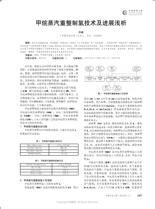
甲烷蒸汽重整制氢技术及进展浅析采用ZnO与H2S反应生成ZnS以深度脱除S。
制氢过程中预重整、蒸汽重整、中温变换使用的催化剂(预重整和蒸汽重整催化剂为Ni/Al2O3,中温水气变换催化剂为Fe3O4/Cr2O3或ZnO/ZnAl2O4)容易被硫化物中毒失活,为深度脱除原料中的硫化物,保护下游过程的催化剂,常在预重整前进行加氢脱硫,保证整个制氢体系的长周期稳定运行。
预重整(PR)是将C2+饱和烃转化为C1和H2,避免进料温度过高造成C2+烃热分解积炭,使预重整后的C1和H2可以预热到更高温度。
预重整还可以将微量S充分脱除,保护后续催化剂长周期稳定运行。
此外,预重整的部分原料为合成气(CO+H2),可降低后续高温蒸汽重图1 甲烷蒸汽重整制氢工艺流程198研究与探索Research and Exploration ·工程技术与创新中国设备工程 2023.04 (上)温度约200℃,催化剂为Cu/ZnO/Al 2O 3,产品干气中CO 分数为0.25%。
变压吸附(PSA)是一种应用广泛的低成本氢气提纯工艺,利用不同气体分子在一些高比表面积吸附材料表面的吸附能力差异,通过多次反复吸附-脱附,最终将不同吸附能力的组分分离出来。
变压吸附包含吸附(A-Adsorption)、降压/均压(E 1-Pressure equalization)、顺放(PP-Provide purge)、逆放(D-Dump)、冲洗(P-Purging/Regeneration)、升压/均压(R 1/R 0-Repressurization)等六个步骤。
常规的吸附分离具有能耗低、压损小、纯度高、投资小、流程短、操作弹性范围大、原料适应性强等众多优点,但收率较低。
采用变压吸附后,氢气回收率提高到75~95%,氢气纯度提高到99.9%以上。
若氢气价值高,还可以采用真空变压吸附(VPSA)提高氢气回收率至95%以上。
甲烷蒸汽重整制氢技术经百年发展,工艺成熟,装置完善,经济可靠,制氢能力强,适合规模化生产,但也存在原料利用率不高和工艺复杂、操作难度大的缺点,不容忽视。
二氧化碳转化为合成气及高附加值产品的研究进展
化工进展Chemical Industry and Engineering Progress2022年第41卷第3期二氧化碳转化为合成气及高附加值产品的研究进展邵斌,孙哲毅,章云,潘冯弘康,赵开庆,胡军,刘洪来(华东理工大学化学与分子工程学院,上海200237)摘要:由于二氧化碳(CO 2)过度排放导致全球变暖日益严峻,发展零碳技术已成为人类社会面向可持续发展的战略选择。
将CO 2捕集并转化为高附加值化学和能源产品,可以优化化石能源为主体的能源结构、有效缓解环境问题,并实现碳资源的充分利用,是一项可以大规模实现低碳减排的技术。
本文重点介绍了CO 2高效利用新途径,通过二氧化碳-合成气-高附加值化学品的产品工艺路线,实现CO 2的资源化利用。
对比综述了热催化法、电催化法和光催化法高效转化合成气的最新进展,总结了热、电、光催化制备合成气过程中催化剂的设计原理和方法以及目前工业化应用前景;简单概述了合成气作为重要平台分子,进一步通过费托合成路线或接力催化路线转化为低碳烯烃和液态燃料或芳烃等化学品过程中催化剂设计研究进展。
最后,总结了大规模工业化CO 2转化为合成气及高附加值产品过程催化剂设计和反应器优化的技术难题,并对未来CO 2高效转化利用方向进行了展望。
同时指出目前各技术还普遍存在反应机理不清晰、催化剂成本高以及缺乏大规模合成等问题,未来开发出高效、高活性、低成本且稳定的催化剂是各技术推广应用的关键。
关键词:二氧化碳;合成气;催化机理;催化剂;工业应用中图分类号:TQ211文献标志码:A文章编号:1000-6613(2022)03-1136-16Recent progresses in CO 2to syngas and high value-added productsSHAO Bin ,SUN Zheyi ,ZHANG Yun ,PAN Fenghongkang ,ZHAO Kaiqing ,HU Jun ,LIU Honglai(School of Chemistry and Molecular Engineering,East China University of Science and Technology,Shanghai 200237,China)Abstract:The global warming caused by excess carbon dioxide (CO 2)emission has been a worldwide focus.The development of carbon neutralization technologies is a strategic choice for the sustainability of human society.CO 2capture and conversion to high value-added chemicals is an ultimate technology for the goal of carbon neutralization,which can optimize the fossil fuel-dominated energy structure,effectively alleviate environmental problems,and achieve carbon recycling.This paper focuses on the efficient CO 2utilization by the route of CO 2-syngas-high value-added chemicals.As an important intermedia product,syngas is the most feasible for CO 2conversion and can be further transformed into value-added chemicals.Recent progresses in three CO 2to syngas technologies of thermo-catalysis,electrocatalysis and photocatalysis are reviewed,including the mechanism,catalysts design strategies,and the current industrial application prospects.Moreover,the conversion of syngas to light olefins and aromatics through the Fischer-Tropsch synthesis and relay catalytic routes are also reviewed.By analyzing and comparing the key technologies,特约评述DOI :10.16085/j.issn.1000-6613.2021-1909收稿日期:2021-09-07;修改稿日期:2021-10-19。
以甲烷为燃料的SOFC研究进展
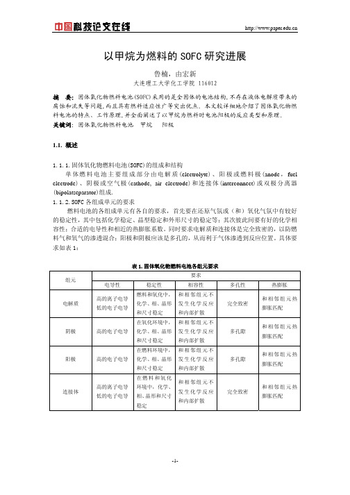
方法是在高温下,在阳极内部CH4直接重整(如图 2.所示),且水蒸汽重整制氢占据了主导地 位。在内部重整型SOFC中,重整反应所需热量由燃料电池反应供给,因而可以省去传统SOFC
的燃料处理器所需的外部热交换器,在燃料电池内部将重整反应与电化学氧化反应偶联将内
部重整由概念变成现实。
甲烷蒸汽重整过程主要进行如下反应:
(5)甲烷在高温下发生了裂解反应,
CH4→C+2H2
(20)
C+H2O→CO+H2
(21)
但是,甲烷直接进入 SOFC 阳极后,在阳极氧化过程复杂,在阳极表面,甲烷的不完全氧
化、积碳等现象均会导致电池性能下降。基于此,我们在研究甲烷直接转化发电基础上,对甲
烷在 SOFC 中的阳极催化氧化机制作深入研究与探讨。
2.1.2.甲烷直接氧化
甲烷结构稳定,完全氧化转化反应的自由能高。天然气在SOFC中的利用方式有两种,其
一,甲烷经外部催化转化成CO和H2混合气,然后进入SOFC阳极发电,这需要复杂的外部重整 转化设备,投资大,增加了工艺的复杂性;其二,将甲烷直接送入SOFC阳极,在SOFC阳极表面
直接完成转化与发电两个过程,是目前SOFC电催化过程研究中的前沿领域。 因为蒸汽重
2.2.阳极氧化性能研究
上述各个反应与O2-的供应速度密切相关。当氧气进入SOFC本体时,氧在阴极上的还原 反应速度及O2-在固体氧化物电解质中的离子传输速率,直接影响到达阳极表面的O2-数目。在 SOFC系统中,希望到达阳极的O2-数目足够多,使甲烷达到完全氧化反应,释放出最多电子数, 获得高的输出电流密度。氧离子在固体氧化物电解质中的迁移机理分析表明,高活性阴极催 化剂、固体电解质的组成及厚度、系统工作温度都会影响到达阳极的O2-数目。此外,在阳极 与固体电解质之间存在三相界面(tpb),研究表明在tpb处,富集着相当数目的O2-,富集的O2-越多, 积碳现象越少。因此,在阳极催化剂分布时,形成较多的tpb区域是有利的。
chemical engineering journal参考文献格式
chemical engineering journal参考文献格式Chemical Engineering Journal (CEJ) 是一本国际性的、综合性的化学工程领域学术期刊,发表原创性的科学研究论文、综述、评论、研究快报等,覆盖了该领域内的核心和前沿研究。
本文将介绍 CEJ 文献的基础引用格式、和其他几种常用引用格式的比较。
1. 基础引文格式CEJ 的基础引文格式为:[1] 作者,论文标题,期刊名称,年代,卷(期):页码.例如:[1] E. Smith, H. Qin, E. Smith, et al., “Research on chemical synthesis of nanoparticles,” Chem. Eng. J., 2010, 166(2): 265-272.其中,“E. Smith, H. Qin, E. Smith, et al.” 表示的是文章的作者。
2. 类似期刊的引文格式除了基础引用格式,还有一些类似期刊的引用格式。
例如,可以在标题前面加上“On the”,即“在...上的研究”:[2] L. Wang, Y. Li, X. Sun, Y. Zou, “On the role of CO2in the wet reforming of methane,” Chem. Eng. J., 2011,166(2): 724-732.或者,在标题后面加上“: An experimental study”:“:一个实验研究”:[3] J. Zhang, Y. Chen, Z. Wang, et al., “Preparation and characterization of mesoporous zirconia: An experimental study,” Chem. Eng. J., 2013, 217: 273-280.3. 书写有误时的引用格式修正有时,因为文献信息的不完整或手写错误等不可控因素,文章作者或期刊名称的书写可能会有错误。
二氧化碳燃烧前捕获技术
山东化工SHANDONG CHEMICAL INDUSTRY・244・2021年第50卷化工:I二氧化碳燃烧前捕获技术刘怡卉(中科弘清(北京)科技有限公司,北京100088)摘要:目前温室效应越来越严重,使我们对二氧化碳的排放越发重视,使得二氧化碳的捕获技术得到了发展。
按C°2的捕获时间,二氧化碳捕获技术可以分为燃烧前捕获技术(pre-ombustion C°2capture)(燃烧后捕获技术(post-combustion C°2capture)和富氧燃烧捕获技术(Oxa-combustion),燃烧前捕获技术比较成熟的技术。
基,论述了二氧化碳燃烧前捕获技术。
关键词:二氧化碳(C°2);燃烧前捕获;二氧化碳储存中图分类号:X511文献标识码:A文章编号:1008-021X(2021)03-0244-03室效目的题,氧化碳的排放是产室效应的因素。
为题,世界都在努力发展低碳经济,以求将二氧化碳的排放量降低。
目,化石燃料发C°2的大排放点源,C°2排放总量的40%⑴。
上世纪90,世界上的发在日本的京都签署了京都议(Kyota Protocol),!统的从规则上制了未来的求;后,世界各大国元聚哈根,参了2009哈根气候峰会,更体现了世界对于节能的重视2015又签署了巴黎协定,为世界规定了更加严格的限制。
二氧化碳不仅可以导致温室效应,同时还可作为的工业原料,火、人工降。
因此衍生了氧化碳治理和利用的技术手段。
1二氧化碳捕获技术氧化碳捕获技术有效应的减少C°2排放的技术,在的几十年,二氧化碳捕获技术了的研究,发展出了如技术、溶剂吸附技术、技术、电化学技术、固体吸附技术等技术⑶。
根据C°2的捕获时间,C°2捕技术可为燃烧前捕获技术(pw-combustion C°2capture)燃烧后捕获技术(pot-conbuwmn C°2capture)和富氧燃烧捕获技术!Oxy-ombustion)⑷。
天然气制乙烯技术进展及经济性分析

2016年第35卷第6期CHEMICAL INDUSTRY AND ENGINEERING PROGRESS ·1733·化工进展天然气制乙烯技术进展及经济性分析胡徐腾(中国化工集团公司,北京 100080)摘要:介绍了当前几种主要的天然气制乙烯技术新进展,包括天然气经甲醇制乙烯、费-托合成制乙烯、甲烷氧化偶联制乙烯技术进展及应用情况,并对这几种工艺进行了技术经济评价,结论认为:天然气制乙烯技术的大规模应用,主要取决于天然气原料供应的有效保障及其价格是否合理,在天然气供应充足、价格合理的条件下,天然气经甲醇制乙烯工艺将会得到较快发展,而费-托合成制乙烯、甲烷氧化偶联制乙烯技术目前尚未达到成熟应用阶段,需要持续加大研发力度,争取早日实现工业化应用。
关键词:天然气;乙烯;甲醇;费-托合成;甲烷氧化偶联;技术进展;经济评价中图分类号:TQ 221.21 文献标志码:A 文章编号:1000–6613(2016)06–1733–06DOI:10.16085/j.issn.1000-6613.2016.06.013Technology progress and economy analysis on natural gas to ethyleneHU Xuteng(China National Chemical Corporation,Beijng 100080,China)Abstract:The current main technology progress of natural gas to ethylene were introduced,including natural gas to ethylene through methanol,Fischer-Tropsch synthesis route,and oxidative coupling of methane. Technical and economic evaluation of these processes were performed,and the conclusions are:the large-scale application of natural gas to ethylene technology mainly depends on the natural gas supply and it’s price. Under the conditions of sufficient gas supply and reasonable price,the technology of natural gas to ethylene through methanol will get a rapid development,while the applications of Fischer-Tropsch synthesis and oxidative coupling of methane technology at present has not yet been mature and it is necessary to continue to intensify their research and development for the realization of their industrial application.Key words: natural gas;ethylene;methanol;Fischer-Tropsch synthesis; oxidative coupling of methane;technical progress;economic evaluation近年来,全球乙烯市场需求强劲,2014年全球乙烯产能达到1.53亿吨/年,需求量1.43亿吨,产量1.3亿吨,由于供应增速低于需求增速,市场供应相对偏紧[1]。
炭和二氧化碳反应的方程式
炭和二氧化碳反应的方程式炭和二氧化碳反应的方程式如下所示:1. 炭和二氧化碳气体的直接反应:C + CO2 -> 2CO这是一个高温条件下的反应,需要提供能量以克服炭和二氧化碳的化学键能,从而产生一分子一氧化碳和一分子碳一氧化物。
2. 炭和二氧化碳气体的间接反应:C + O2 -> CO2CO2 + C -> 2CO这是炭的燃烧反应。
燃烧时,炭与氧气反应生成二氧化碳,然后生成的二氧化碳与剩余的炭发生反应生成一氧化碳。
上述两个方程式是炭和二氧化碳反应的基本方程式。
下面将详细解释这些反应的背后化学原理和相关参考内容。
炭和二氧化碳的直接反应(C + CO2 -> 2CO)是通过热点燃烧或电弧等高温条件下实现的。
这项反应研究的最早记录可以追溯到19世纪,英国化学家雅各布·贝瑞(Jacobus Henricus van't Hoff)在1878年的研究中提到了该反应。
二氧化碳与炭的氧化还原反应在高温下发生,生成一氧化碳和碳一氧化物作为产物。
这些产物在工业上具有一定的应用,例如用于冶金和合成其他有机化合物。
炭和二氧化碳的间接反应是炭的燃烧过程。
在氧气存在的情况下,炭会燃烧生成二氧化碳。
这是一种强放热反应,常被用于加热和能量供应。
这个反应也是自然界中燃料的燃烧过程的基础。
炭和二氧化碳反应的机理和动力学研究在过去几十年中取得了很大的进展。
一些参考文献和研究论文相关的内容包括:1. "Direct Conversion of Carbon Dioxide into Carbon Monoxide and Formate by Photocatalysis" - J. Am. Chem. Soc. 2016, 138, 7423–7426. 这篇论文介绍了一种光催化的方法,将二氧化碳转化为一氧化碳和甲酸。
2. "Thermal Decomposition of Carbonates: Homogeneous and Heterogeneous Reactions" - J. Phys. Chem. A 2002, 106, 8774-8782. 这篇论文研究了碳酸盐的热分解反应,包括二氧化碳和炭的反应。
天然气水蒸汽重整商品催化剂上的沼气重整制氢

第5期天然气水蒸汽重整商品催化剂上的沼气重整制氢徐军科1,2,周伟2,王晓蕾1,2,任克威3,潘相敏2,陈华强4,王业勤5,马建新2*(1.同济大学环境科学与工程学院,上海200092;2.同济大学新能源汽车工程中心,上海201804;3.华东理工大学资源与环境工程学院,上海200237;4.上海燃料电池汽车动力系统有限公司,上海200237;5.四川亚联高科技有限责任公司,成都610041)摘要:研究了将工业天然气水蒸汽重整催化剂Z118Y用于由等摩尔的甲烷和二氧化碳组成的模拟沼气的重整反应。
考察了反应温度、空速、压力、还原温度及氧气含量对催化剂性能的影响。
并运用BET、TG-DSC、TEM及H2-TPR对催化剂进行了表征。
实验结果表明:还原温度对催化剂的活性及稳定性有很大的影响,反应气中适量添加氧气能提高甲烷转化率、一氧化碳选择性、H2/CO比、防止催化剂表面积炭并延长催化剂使用寿命。
关键词:商品重整催化剂;沼气重整;制氢中图分类号:O643文献标识码:A文章编号:1001-9219(2008)05-33-05天然气化工2008年第33卷式中X、S、F分别表示反应物转化率、产物选择性及物料体积流量(F i=F total·φi,其中F total为产物的总体积流量,φi为产物中组分i的体积分数)。
1.2催化剂的表征催化剂的比表面积(BET)及孔结构由Micromeritics公司的ASAP2020比表面及孔结构分析仪进行测试,约0.1g样品先在250℃下脱气预处理4h,然后在-196℃下进行氮气的吸-脱附等温实验。
催化剂的积炭量采用NETZSCH STA 449C热分析仪(TG-DSC)进行测定:升温速率为10℃/min,以氮气作为保护气,空气作为氧化剂,空Al2O3坩锅为参比。
催化剂的微观结构与形态用日立公司的H-800型透射电镜(TEM)测试,加速电压为200kV。
催化剂的还原性能由Micromeritics公司的Aut℃hem II-2920上的程序升温氢还原(H2-TPR)测定:约0.1g样品于120℃下,30mL/min氩气吹扫40min之后降温至35℃,然后切换成10%H2/Ar(体积比),30mL/min,以10℃/min升温至900℃。
液相合成甲基醇
CuZnAlSi 的催化性能袁并分析了改进的原因遥 结果表明院完全液相法制备 Mn 改性 CuZnAlSi 催化剂液相合成甲醇有好稳定
性袁Mn鄄CuZnAlSi 能提高甲醇选择性和催化活性袁Mn鄄CuZnAlSi (CZAS鄄0.08Mn)浆状催化剂在 250益袁5.0MPa 下反应 144h 未见失
17
这是 CuMnOx 复合物中组分 Cu/Mn 比例改变影响 了还原峰温的位置袁因为这种 Cu鄄Mn 间的强相互作 用袁可能通过 Cu鄄O鄄Mn 间的氧桥或者轨道间的电子 交换渊d鄄d袁s鄄s冤产生袁亦或是 Mn 覆盖于次表层的 Cu 需要较高能量才能被还原袁从而使还原峰温增加[14]遥
1鄄CZAS曰2鄄CZAS鄄0.04Mn曰3鄄CZAS鄄0.08Mn曰4鄄CZAS鄄0.12Mn曰 5鄄CZAS鄄0.20Mn
网络出版时间:2013-08-03 16:35 网络出版地址:/kcms/detail/51.1336.TQ.20130803.1635.004.html
第4期
喻仕瑞等院液相合成甲醇催化剂稳定性的改进
15
液相合成甲醇催化剂稳定性的改进
喻仕瑞 1,2袁高志华 1袁栾春晖 1袁王晓东 1袁高珊珊 2袁 黄 伟 1*
催化剂 H2鄄TPR 谱图见图 3遥所有还原峰都不对 称袁有拖尾现象袁并随 Mn 量的增加拖尾现象从低温 逐渐向高温转移袁 这是因为 Cu 与 Mn 的氧化物形 成了 CuMnOx 复合物所致 遥 [12] CZAS鄄0.04Mn尧CZAS鄄 0.08Mn 和 CZAS鄄0.12Mn 还原峰温都要比 CZAS 低袁 且随 Mn 量增加袁可还原氧化物量和还原峰温递减, 表明 Mn 能促进 Cu 的氧化物还原袁这与文献[11]报 道一致遥 但 Mn 量增加到 0.20mol袁这种趋势不再延 续袁其可还原物质与峰温有所增加袁还原峰较宽化袁
甲烷二氧化碳重整制氢

Research ArticleNi/SiO2Catalyst Prepared with Nickel NitratePrecursor for Combination of CO2Reforming andPartial Oxidation of Methane:Characterization and Deactivation Mechanism InvestigationSufang He,1Lei Zhang,2Suyun He,2Liuye Mo,3Xiaoming Zheng,3Hua Wang,1and Yongming Luo21Research Center for Analysis and Measurement,Kunming University of Science and Technology,Kunming650093,China2Faculty of Environmental Science and Engineering,Kunming University of Science and Technology,Kunming650500,China3Institute of Catalysis,Zhejiang University,Key Lab of Applied Chemistry of Zhejiang Province,Hangzhou310028,ChinaCorrespondence should be addressed to Y ongming Luo;environcatalysis222@Received5August2014;Revised6January2015;Accepted6January2015Academic Editor:Mohamed BououdinaCopyright©2015Sufang He et al.This is an open access article distributed under the Creative Commons Attribution License, which permits unrestricted use,distribution,and reproduction in any medium,provided the original work is properly cited.The performance of Ni/SiO2catalyst in the process of combination of CO2reforming and partial oxidation of methane to produce syngas was studied.The Ni/SiO2catalysts were prepared by using incipient wetness impregnation method with nickel nitrate as a precursor and characterized by FT-IR,TG-DTA,UV-Raman,XRD,TEM,and H2-TPR.The metal nickel particles with the average size of37.5nm were highly dispersed over the catalyst,while the interaction between nickel particles and SiO2support is relatively weak.The weak NiO-SiO2interaction disappeared after repeating oxidation-reduction-oxidation in the fluidized bed reactor at 700∘C,which resulted in the sintering of metal nickel particles.As a result,a rapid deactivation of the Ni/SiO2catalysts was observed in2.5h reaction on stream.1.IntroductionThe Ni-based catalyst has recently attracted considerable attention due to the plentiful resources of nickel,as well as its low cost and good catalytic performance comparable to those of noble metals for many catalytic reactions,such as hydrogenation of olefins and aromatics[1],methane reforming[2],and water-gas shift reaction[3].Therefore,Ni-based catalyst is believed to be the most appropriate catalyst applied in the industrial process[4–6].It is generally accepted that the catalytic performance of Ni-based catalyst is closely related to several parameters,including the properties of support,preparation method,and active phase precursor employed.Support plays an important role in determining the performance of Ni-based catalyst.Generally,a support with high surface areas is very necessary since it is effective in increasing Ni dispersion and improving thermal stability, hence not only providing more catalytically active sites,but also decreasing the deactivation over time of the catalysts due to sintering and migration effects[7,8].For its good thermostability,availability,and relative high specific surface area,SiO2support was widely used for preparing Ni-based catalyst[9].In particular,spherical silica is successfully used as a catalyst support in fluidized bed reactor due to its high mechanical strength.The method of catalyst preparation is another key param-eter which needs to be optimized because it will result in different structural and textural properties of Ni-based catalyst.Therefore,numerous methods,including precipi-tation,homogeneous deposition-precipitation,and sol-gel techniques,have been developed to enhance the performance of Ni-based catalyst[10–18].However,allthe above method-ologies mentioned are too complex or expensive to scaleHindawi Publishing Corporation Journal of NanomaterialsVolume 2015, Article ID 659402, 8 pages /10.1155/2015/659402up in industry.The incipient wetness impregnation(IWI) is one of the most extensively used method[19–23]due to its simplicity in practical execution on both laboratory and industrial scales,in addition to its facility in controlling the loading amount of the active ingredient.In addition,the choice of the precursor salt is also crucial since it determines whether the Ni-based catalyst will be prepared successfully or not.As an efficient precursor,two terms must be met:firstly,high solubility is desirable because the precursor concentration in the impregnation solution must be high[24];secondly,the ability to be decomposed during calcinations is prerequisite since the precursor must be fully transformed into oxide particles without leaving side species that may modify the properties of the support [24].As a result,owing to its commercial availability and low cost,as well as its high solubility in water and effortless decomposition at moderate temperatures,nickel nitrate is the precursor most often used in the preparation of Ni-based catalyst[23,24].In this paper,Ni/SiO2catalyst was prepared by incipient wetness impregnation(IWI)with nickel nitrate as precursor and tested in the process of combination of CO2reforming and partial oxidation of methane(CRPOM)to produce syngas.TG-DTA,HR-TEM,IR,UV-Raman,XRD,and H2-TPR were employed to characterize the Ni/SiO2catalysts in detail to reveal the relationship between synthesis,properties, and catalytic performances as well as to investigate the causes of deactivation.2.Experimental Section2.1.Catalyst Preparation.The Ni/SiO2catalysts were pre-pared with IWI using nickel nitrate as precursor according to our previous works[21,22].The SiO2was commer-cially obtained(S BET=498.8m2/g,Nanjing Tianyi Inorganic Chemical Factory).Prior to use,the SiO2was pretreated with5%HNO3aqueous solution for48h and then washed with deionized water until the filtrate was neutrality.The size of SiO2was selected between60and80mesh.It was then impregnated with an aqueous solution of nickel nitrate. The obtained sample was dried overnight at100∘C and subsequently calcined in air at700∘C for4h.Unless otherwise stated,the loading of Ni was3wt%,and the calcination temperature was700∘C.The Ni/SiO2catalyst was designated as3NiSN.2.2.Catalytic Reaction.The catalytic reaction was performed in a fluidized-bed reactor that was comprised of a quartz tube (I.D.=20mm,H=750mm)under atmospheric pressure at700∘C.Prior to reaction,2mL of catalyst was reduced at700∘C for60min under a flow of pure hydrogen at atmospheric pressure with a flow rate of50mL/min.A reactant gas stream that consisted of CH4,CO2,and O2,with a molar ratio of1/0.4/0.3,was used with a gas hourly space velocity(GHSV)of9000h−1.The feed gas was controlled by mass flow controllers.The effluent gas cooled in an ice trap was analyzed with an online gas chromatograph that was equipped with a packed column(TDX-01)and a thermal conductivity detector.Under our reaction conditions,the oxygen in the feed gas was completely consumed in all cases.2.3.Catalyst Characterization.FTIR spectra were measured using a Nicolet560spectrometer equipped with a MCT detector.The samples were tabletted to thin discs with KBr.Thermogravimetric analysis(TGA)and differential ther-mal analysis(DTA)were performed on a PERKIN ELMER-TAC7/DX with a heating rate of10∘C/min under oxygen (99.99%,20mL/min).The samples were pretreated with oxygen flow at383K for1h.UV-Raman spectra were carried out with a Jobin Yvon LabRam-HR800instrument,using325.0nm Ar+laser radi-ation.The excitation laser was focused down into a round spot approximately2μm in diameter.The resolution was 4cm−1and1000scans were recorded for every spectrum.The catalysts were ground to particle diameters<150μm before analysis.X-ray powder diffraction(XRD)patterns of samples were obtained with an automated power X-ray diffractometer (Rigku-D/max-2550/PC,Japan)equipped with a computer for data acquisition and analysis,using Cu Kαradiation, at40kV and300mA.The reduced samples were priorly reduced at700∘C for1h and cooled to room temperature in hydrogen atmosphere,but the fresh samples were used directly after calcined in air at700∘C for4h.All the samples were ground to fine powder in an agate mortar before XRD measurements.Transmission electron microscopy(TEM)images were recorded on a Philips-FEI transmission electron microscope (Tecnai G2F30S-Twin,Netherlands),operating at300kV. Samples were mounted on a copper grid-supported carbon film by placing a few droplets of ultrasonically dispersed suspension of samples in ethanol on the grid,followed by drying at ambient conditions.H2-temperature-programmed reduction(H2-TPR) experiments were performed in a fixed-bed reactor(I.D.= 4mm).50mg samples were used and reduced under a stream of5%H2/N2(20mL/min)from50∘C to800∘C with a ramp of7∘C/min.Hydrogen consumption of the TPR was detected by a TCD and its signal was transmitted to a personal computer.The experiments for reduction-oxidation cycle(redox) performance were performed as follows.The catalysts were pretreated with H2flow at700∘C for1h and then were cooled down to room temperature and reoxidized in O2at different temperature for1h.The reoxidized samples were then performed by H2-TPR experiments as above.3.Results and Discussion3.1.Catalytic Activity Measurements.The catalytic perfor-mance of Ni/SiO2was shown in Figure1.A rapid deactivation was detected for the3NiSN,and the corresponding conver-sion of CH4(X CH4)decreased from∼58%to∼25%within 1.5h reaction on stream.In order to investigate the causes of deactivation,the3NiSN catalyst was characterized by TG-DTA,HR-TEM,IR,UV-Raman,XRD,and H2-TPR in detail.Time on stream (h)60555045403530252015C o n v e r s i o n o f C H 4(%)Figure 1:CH 4conversion versus time on 3NiSN catalyst for combination of CO 2reforming and partial oxidation of methane to produce syngas (reaction temperature:700∘C,CH 4/CO 2/O 2=1/0.4/0.3,and GHSV =9000h −1).Wavenumber (nm)Figure 2:FT-IR spectra of 3NiSN (dried at 100∘C)and nickel nitrate (Ni(NO 3)2).3.2.Catalyst Characterization Results3.2.1.FT-IR Analysis.The FT-IR spectra of 3NiSN before cal-cination and Ni(NO 3)2precursor were illustrated in Figure 2.Two intense bands of Ni(NO 3)2centered at 1620cm −1and 1376cm −1were ascribed to asymmetric and symmetric vibra-tions of nitrate,respectively [25].After Ni(NO 3)2being impregnated on SiO 2,the position of the two bands of Ni(NO 3)2shifted to higher wavenumber about 1643cm −1and1385cm −1,respectively.Similar to our previous study [23],this shift to higher wavenumber might be contributed to the interaction between nickel nitrate and support SiO 2.3.2.2.Thermal Analysis.In order to study the formation of NiO from precursor,thermal analysis of 3NiSN before calcination was carried out (shown in Figure 3).The extra water should be removed by holding the precursor under O 2at 110∘C for 1h.The thermal oxidation degradation of the dried 3NiSN consisted of two main steps.The first weight loss (9.1wt%)at 110–240∘C region in TG together with a differential peak at around 224∘C in DTG curve was probably due to the dehydration of 3NiSN.The second large weight loss at region of 240–380∘C (11.1wt%)in TG,accompanied with a small endothermic peak around 293∘C in DTA,had been attributed to thermoxidative degradation of nickel nitrate.This decomposition step exhibited a differential peak around 277∘C in DTG profile.Above 380∘C,practically weight loss could not be observed any more.The TG-DTA curves confirmed the absolute volatility of water and nitrate and also the formation of NiO over catalysts around 380∘C.The calcination of 3NiSN beyond 380∘C would enhance the interaction between the NiO and SiO 2support,according to our earlier study [23].3.2.3.UV-Raman Analysis.Further evidence for the for-mation of NiO might be drawn from UV-Raman spectra exhibited in Figure 3.Herein,the spectrum for NiO was included as a reference.As seen from Figure 4,the intense and sharp peak at 1139cm −1,together with three weak peaks at 900,732,and 578cm −1,was assigned to the Raman responses of NiO.Similar to NiO reference,the peaks of 3NiSN center at about 1135,900,726,and 580cm −1were also attributed to NiO.Furthermore,compared with the reference of NiO,the four Raman peaks of NiO over 3NiSC appeared more intensive,thus suggesting that the NiO particles over 3NiSN catalyst were larger [23,26,27].3.2.4.XRD Analysis.XRD measurements were carried out to understand the crystalline structure of 3NiSN catalysts,and the results were presented in Figure5.The XRD patterns of all samples exhibited a broad and large peak around 22∘,which was attributed to amorphous silica of support.After calcination,the sample showed only the fcc-NiO phase,with typical reflections of the (111),(200),and (220)planes at 2θ=37∘,43∘,63∘,respectively.After being reduced with H 2for 4h,the peaks assigned to NiO disappeared,and three other peaks around 44∘,52∘,and 76∘for Ni (111),Ni (200),and Ni (220)planes were detected,thus inferring the successful transformation of NiO to metallic Ni after reduction with H 2.3.2.5.TEM Analysis.Further insight on the aggregation of Ni particles over the 3NiSN could be obtained by TEM analysis.Figures 6(a)and 6(b)exhibited the TEM images of 3NiSN after reduction and deactivation,respectively.The Ni particles over both catalysts were approximately spherical in shape.Highly dispersed Ni particles were detected for the Ni/SiO 2just after reduction.However,obvious glomeration200300400500600700Temperature (∘C)T G +D T G(a)200300400500600700Temperature (D T A∘C)(b)Figure 3:(a)TG +DTG and (b)DTA thermogram of 3NiSN dried at 100∘C.Raman shift (cm −1)I n t e n s i t y (a .u .)Figure 4:UV-Raman spectra of 3NiSN (calcined at 700∘C for 4h)and NiO (as a reference).of Ni particles was observed for the 3NiSN catalyst after deactivation.In order to make a profound analysis,the corresponding particle size distributions obtained from TEM were summarized in Figures 6(c)and 6(d)for 3NiSN after reduction and deactivation,respectively.The particle size values of reduced 3NiSN were distributed in a range of 16.1–84.0nm with the average size around 37.5nm.As for 3NiSN after deactivation,the mean size increased to 50.4nm2θ(deg)Ni NiOI n t e n s i t y (a .u .)Figure 5:XRD patterns of 3NiSN before and after reduction in H 2for 4h.with distributed range of 36.0–73.6nm.An evident particle aggregation was formed over 3NiSN catalyst,which was in accordance with the XRD result.3.2.6.H 2-TPR Analysis.TPR is an efficient method to char-acterize the reducibility of supported nickel-based catalysts.(a)(b)Particle diameter (nm)0.250.200.150.100.050.00R e l a t i v e p a r t i c l e n u m b e r (%)(c)0.200.150.100.050.00R e l a t i v e p a r t i c l e n u m b e r (%)Particle diameter (nm)(d)Figure 6:TEM images of (a)reduced 3NiSN and (b)deactivated 3NiSN,and histogram of the particle size distribution obtained from sampling of nanoparticles from TEM data (c)for reduced 3NiSN and (d)for deactivated 3NiSN.TPR profiles of 3NiSN catalysts were depicted in Figure 7.Two reduction peaks were observed for the fresh 3NiSN cata-lyst (just calcined)at 430∘C and 450∘C.The low-temperature peak might be contributed to the reduction of NiO which is negligible weak interaction with SiO 2.The high-temperature peak was caused by the reduction of nickel oxide which interacted weakly with SiO 2.Furthermore,ttthe reduction-oxidation cycle (redox)performance of a catalyst would strongly influence the catalytic activity for an oxidation involved reaction [28].Therefore,the redox performances of 3NiSN catalysts were investigated,and the corresponding experiment results were depicted in Figure 7.After beingreduced in H 2flow at 700∘C for 1h,the 3NiSN catalysts were reoxidized in O 2at different temperatures and then tested with H 2-TPR.No clear reduction peak of NiO was detected for 3NiSN with reoxidized temperature below 300∘C.As reoxidization temperature increased from 400to 700∘C,the rereduction temperature increased from ∼290to ∼370∘C;however,it was always less than the temperature needed to reduce the NiO of fresh 3NiSN.Distinctly,the weak NiO-SiO 2interaction over 3NiSN catalyst disappeared with repeat-ing oxidation-reduction-oxidation process.Studies from the previous work show that the strong interaction between NiO and support could suppress efficiently the sintering of200300400500600Temperature (FED C B A∘C)H 2c o n s u m p t i o n (a .u .)Figure 7:The reduction-oxidation cycle (redox)performance of 3NiSN catalysts with different reoxidization temperature (A:300∘C;B:400∘C;C:500∘C;D:600∘C;E:700∘C;F:fresh,just calcined).metallic nickel [21–23].Therefore,the disappearance of NiO-SiO 2interaction would lead to the sintering of active nickel particles at high reaction temperature.3.2.7.Effect of the Particle Size of Ni.It is generally accepted that the crystalline size of metallic nickel plays an important role in the catalytic performance for nickel-catalyzed reac-tions:smaller metallic Ni size helps to provide more active sites to reach the much better catalytic activity.Our previous works had also demonstrated this view [21,22].In order to investigate the particle size dependence of the catalytic reaction,the 3NiSN catalysts after different time (1.5h,2.0h,and 2.5h)reaction on stream were taken out to be estimated by XRD and calculated with the Scherrer equation (shown in Figure 8).For all the 3NiSN (even after deactivation),only Ni and amorphous SiO 2phase detected by XRD.No NiO phase was found,which meant no significant change in Ni phase was observed for 3NiSN even after deactivation.Noteworthily,the diffraction intensity of nickel crystalline increased with reaction time,which indicated the crystalline size of nickel on 3NiSN increased with reaction time.The crystalline size of nickel on 3NiSN as a function of reaction time was shown in Figure 9.The crystalline size of nickel was ∼30.3nm,∼32.6nm,∼33.6nm,and ∼34.6nm,for 3NiSN after 0h,1.5h,2h,and 2.5h reaction on stream,respectively.The change trend of Ni size was in conformance with the catalytic activity of 3NiSN in process of bined with H 2-TPR results above,with the process of CRPOM proceeding,the NiO-SiO 2interaction over 3NiSN catalyst weakened down as it disappeared.At the same time,the crystalline size of nickel increased with the weakening of NiO-SiO 2interaction,finally leading to the sintering of active nickel particles over 3NiSNcatalyst.2θ(deg)NiI n t e n s i t y (a .u .)Figure 8:The effect of reaction time on the XRD patterns of3NiSN.Reaction time (h)353433323130C r y s t a l l i n e s i z e o f n i c k e l (n m )Figure 9:Crystalline size of nickel as a function of reaction time.By comprehensively analyzing the characterization results,important information could be concluded.On one hand,graphic carbon was not detected in the spent 3NiSN catalyst by XRD and TEM,suggesting that no carbon deposition was formed during the reaction.On the other hand,except for the characteristic XRD peak of metallic nickel,no other nickel species (such as NiO)was detected,indicating that the transformation of active metallic Ni was not the reason for deactivation of 3NiSN.Importantly,the weak interaction between Ni and support disappeared asthe reaction proceeding,resulting in sintering of active nickel particles.This was the reason that3NiSN catalyst showed a rapid deactivation in the CRPOM reaction.4.ConclusionsIn this work,Ni/SiO2catalysts were prepared with nickel nitrate precursor by IWI method and characterized by FT-IR,TG-DTA,UV-Raman,XRD,TEM,and H2-TPR.By being calcined around380∘C,water and nitrate were volatilized absolutely to form NiO,which could be reduced into metallic Ni after being treated with H2at700∘C.The active nickel particles(around37.5nm)of3NiSN catalyst were dispersed highly but weakly interacted with SiO2support.However, this weak interaction disappeared after repeating oxidation-reduction-oxidation in the fluidized bed reactor at700∘C. Therefore,3NiSN catalyst suffered from obvious sintering of the active nickel particle.In light of these,a rapid deactivation of3NiSN was shown in the process of combination of CO2 reforming and partial oxidation of methane(CRPOM)to produce syngas.Conflict of InterestsThe authors declare that there is no conflict of interests regarding the publication of this paper. AcknowledgmentsThe authors thank the financial supports of National Natural Foundation of China(nos.21003066,21367015,and51068010) and Zhejiang Province Key Science and Technology Innova-tion Team(2012R10014-03).References[1]B.Pawelec,P.Casta˜n o,J.M.Arandes et al.,“Katalizatory ni-klowe i rutenowo-niklowe na no´s nikach zawierających zeolit ZSM-5i tlenek glinu.Wybrane wła´s ciwo´s ci fizykochemiczne i katalityczne,”Applied Catalysis A:General,vol.7,no.7,pp.20–33,2007.[2]T.V.Choudhary and V.R.Choudhary,“Energy-efficient syngasproduction through catalytic oxy-methane reforming reac-tions,”Angewandte Chemie,vol.47,no.10,pp.1828–1847,2008.[3]K.-R.Hwang,S.-W.Lee,S.-K.Ryi,D.-K.Kim,T.-H.Kim,and J.-S.Park,“Water-gas shift reaction in a plate-type Pd-membrane reactor over a nickel metal catalyst,”Fuel Processing Technology, vol.106,pp.133–140,2013.[4]D.P.Liu,X.-Y.Quek,H.H.A.Wah,G.M.Zeng,Y.D.Li,andY.H.Yang,“Carbon dioxide reforming of methane over nickel-grafted SBA-15and MCM-41catalysts,”Catalysis Today,vol.148, no.3-4,pp.243–250,2009.[5]V.R.Choudhary,B.S.Uphade,and A.S.Mamman,“Partialoxidation of methane to syngas with or without simultaneous CO2and steam reforming reactions over Ni/AlPO4,”Microp-orous and Mesoporous Materials,vol.23,no.1-2,pp.61–66,1998.[6]E.Ruckenstein and Y.H.Hu,“Combination of CO2reformingand partial oxidation of methane over NiO/MgO solid solution catalysts,”Industrial and Engineering Chemistry Research,vol.37,no.5,pp.1744–1747,1998.[7]J.Newnham,K.Mantri,M.H.Amin,J.Tardio,and S.K.Bhargava,“Highly stable and active Ni-mesoporous alumina catalysts for dry reforming of methane,”International Journal of Hydrogen Energy,vol.37,no.2,pp.1454–1464,2012.[8]M.Garc´ıa-Di´e guez,I.S.Pieta,M.C.Herrera,rrubia,and L.J.Alemany,“Nanostructured Pt-and Ni-based catalysts for CO2-reforming of methane,”Journal of Catalysis,vol.270, no.1,pp.136–145,2010.[9]L.Yao,J.Zhu,X.Peng,D.Tong,and C.Hu,“Comparative studyon the promotion effect of Mn and Zr on the stability of Ni/SiO2 catalyst for CO2reforming of methane,”International Journal of Hydrogen Energy,vol.38,no.18,pp.7268–7279,2013.[10]S.Tada,T.Shimizu,H.Kameyama,T.Haneda,and R.Kikuchi,“Ni/CeO2catalysts with high CO2methanation activity and high CH4selectivity at low temperatures,”International Journal of Hydrogen Energy,vol.37,no.7,pp.5527–5531,2012.[11]I.Rossetti,C.Biffi,C.L.Bianchi et al.,“Ni/SiO2and Ni/ZrO2catalysts for the steam reforming of ethanol,”Applied Catalysis B:Environmental,vol.117-118,pp.384–396,2012.[12]X.L.Yan,Y.Liu,B.R.Zhao,Y.Wang,and C.-J.Liu,“Enhancedsulfur resistance of Ni/SiO2catalyst for methanation via the plasma decomposition of nickel precursor,”Physical Chemistry Chemical Physics,vol.15,no.29,pp.12132–12138,2013. [13]W.S.Xia,Y.H.Hou,G.Chang,W.Z.Weng,G.-B.Han,and H.-L.Wan,“Partial oxidation of methane into syngas(H2+CO) over effective high-dispersed Ni/SiO2catalysts synthesized by a sol-gel method,”International Journal of Hydrogen Energy,vol.37,no.10,pp.8343–8353,2012.[14]L.Li,S.He,Y.Song,J.Zhao,W.Ji,and C.-T.Au,“Fine-tunable Ni@porous silica core-shell nanocatalysts:synthesis, characterization,and catalytic properties in partial oxidation of methane to syngas,”Journal of Catalysis,vol.288,pp.54–64, 2012.[15]D.P.Liu,Y.F.Wang,D.M.Shi et al.,“Methane reformingwith carbon dioxide over a Ni/ZiO2-SiO2catalyst:influence of pretreatment gas atmospheres,”International Journal of Hydrogen Energy,vol.37,no.13,pp.10135–10144,2012. [16]M.V.Bykova,D.Y.Ermakov,V.V.Kaichev et al.,“Ni-based sol-gel catalysts as promising systems for crude bio-oil upgrading:guaiacol hydrodeoxygenation study,”Applied Catalysis B:Environmental,vol.113-114,pp.296–307,2012. [17]M.Xue,S.Hu,H.Chen,Y.Fu,and J.Shen,“Preparationof highly loaded and dispersed Ni/SiO2catalysts,”Catalysis Communications,vol.12,no.5,pp.332–336,2011.[18]R.Nares,J.Ram´ırez,A.Guti´e rrez-Alejandre,and R.Cuevas,“Characterization and hydrogenation activity of Ni/Si(Al)—MCM-41catalysts prepared by deposition-precipitation,”Indus-trial and Engineering Chemistry Research,vol.48,no.3,pp.1154–1162,2009.[19]A.Corma,A.Martinez,V.Martinezsoria,and J.B.Monton,“Hydrocracking of vacuum gasoil on the novel mesoporous MCM-41aluminosilicate catalyst,”Journal of Catalysis,vol.153, no.1,pp.25–31,1995.[20]T.Halachev,R.Nava,and L.Dimitrov,“Catalytic activityof(P)NiMo/Ti-HMS and(P)NiW/Ti-HMS catalysts in the hydrogenation of naphthalene,”Applied Catalysis A:General, vol.169,no.1,pp.111–117,1998.[21]S.He,H.Wu,W.Yu,L.Mo,H.Lou,and X.Zheng,“Combi-nation of CO2reforming and partial oxidation of methane to produce syngas over Ni/SiO2and Ni–Al2O3/SiO2catalysts with different precursors,”International Journal of Hydrogen Energy, vol.34,no.2,pp.839–843,2009.[22]S.F.He,Q.S.Jing,W.J.Yu,L.Y.Mo,H.Lou,and X.M.Zheng,“Combination of CO2reforming and partial oxidation of methane to produce syngas over Ni/SiO2prepared with nickel citrate precursor,”Catalysis Today,vol.148,no.1-2,pp.130–133,2010.[23]S.He,X.Zheng,L.Mo,W.Yu,H.Wang,and Y.Luo,“Characterization and catalytic properties of Ni/SiO2catalysts prepared with nickel citrate as precursor,”Materials Research Bulletin,vol.49,pp.108–113,2014.[24]E.Marceau,M.Che,J.ˇCejka,and A.Zukal,“Nickel(II)nitrate vs.acetate:influence of the precursor on the structure and reducibility of Ni/MCM-41and Ni/Al-MCM-41catalysts,”ChemCatChem,vol.2,no.4,pp.413–422,2010.[25]J.Chen and Q.Z.Song,Organic Spectral Analysis,BIT Press,Beijing,China,1996.[26]J.F.Xu,W.Ji,Z.X.Shen et al.,“Raman spectra of CuOnanocrystals,”Journal of Raman Spectroscopy,vol.30,no.5,pp.413–415,1999.[27]H.Richter,Z.P.Wang,and L.Ley,“The one phonon Ramanspectrum in microcrystalline silicon,”Solid State Communica-tions,vol.39,no.5,pp.625–629,1981.[28]Z.Zhao,Y.Yamada,A.Ueda,H.Sakurai,and T.Kobayashi,“The roles of redox and acid-base properties of silica-supported vanadia catalysts in the selective oxidation of ethane,”Catalysis Today,vol.93–95,pp.163–171,2004.Scientifica Corrosion Polymer ScienceCeramics Composites Nanoparticles International Journal of Biomaterials Nanoscience TextilesJournal of Nanotechnology Crystallography The Scientific World Journal Coatings Advances in Materials Science and Engineering S mart MaterialsResearch Metallurgy Journal ofBioMed Research International Materials Journal of Journal ofNanomaterials。
纳米催化二氧化碳制甲醇英文

纳米催化二氧化碳制甲醇英文Nanocatalysis for the Production of Methanol from Carbon Dioxide.Carbon dioxide (CO2) is a significant greenhouse gas that contributes to global warming. However, converting it into useful chemicals such as methanol offers a sustainable and environmentally friendly approach to mitigate its adverse effects. Nanocatalysis, a field that utilizes nanoscale materials to catalyze chemical reactions, has emerged as a promising technology for this purpose.Nanocatalysis Principles and Applications.Nanocatalysis leverages the unique properties of nanomaterials, including their large surface area and high reactivity, to enhance catalytic activity. These nanomaterials, often in the form of nanoparticles or nanostructures, can significantly improve the rate and selectivity of chemical reactions. In the context of CO2conversion, nanocatalysts can lower the activation energy required for the reaction, making it more energetically favorable.CO2 to Methanol Conversion.The conversion of CO2 into methanol involves a multi-step process known as the methanol synthesis. Typically, this process requires high temperatures and pressures, as well as a suitable catalyst. Nanocatalysts cansignificantly reduce these requirements, making the process more energy-efficient and cost-effective.The most common nanocatalysts used for CO2 hydrogenation to methanol are based on copper. Copper nanoparticles, due to their high activity and selectivity, are particularly effective in promoting this reaction. Other metals, such as palladium and platinum, have also been explored for this purpose.Nanocatalyst Design and Optimization.The design and optimization of nanocatalysts for CO2 conversion are crucial for achieving high catalytic performance. Factors such as particle size, shape, and composition can significantly influence the catalytic activity. For instance, smaller nanoparticles typically exhibit higher catalytic activity due to their increased surface area. Similarly, the choice of support material can also affect the stability and activity of the nanocatalyst.Challenges and Future Prospects.While nanocatalysis offers significant potential for CO2 conversion, several challenges need to be addressed. One of the main challenges is the scalability of nanocatalysts for industrial applications. Current methods for synthesizing nanomaterials are often not suitable for large-scale production. Additionally, the stability of nanocatalysts under reaction conditions is also a concern, as they can often deactivate or agglomerate over time.Future research efforts should focus on developing more stable and scalable nanocatalysts for CO2 conversion.Innovations in nanomaterials synthesis and characterization techniques can help address these challenges. Furthermore, integrating nanocatalysts with other renewable energy sources, such as solar or wind power, can further enhance the sustainability of the process.In conclusion, nanocatalysis holds promise for the efficient conversion of CO2 into methanol. By leveraging the unique properties of nanomaterials, we can develop more effective and sustainable catalysts for this important reaction. Future research in this area could lead to significant advancements in green chemistry and help mitigate the impact of climate change.。
催化剂制备工艺
催化剂制备工艺1 催化剂的载体甲烷自热重整所用催化剂的载体需要具有适当的晶相组成、比表面和孔结构,以有利于反应物分子在催化剂表面吸附、活化,同时也有利于产物分子脱附而离开催化剂表面,防止积炭反应的发生此外载体还应具有较好的机械强度。
目前研究较多的载体有Al2O3、MgO、SiO2、TiO2、CeO2、ZrO2、SiO2-Al2O3Y型分子筛等。
Bhattacharya等[1]考察了在温度为1023K,空速为5000h-1,CH4/O2为8:1时,负载在不同载体上的Pt催化剂的部分氧化反应结果。
所用的催化剂载体分别为IIIA,IV A金属氧化物和稀土金属氧化物,γ-AL2O3和SiO2。
研究表明,因载体不同,甲烷转化率在33.4%到66.9%之间变化,除SiO2外,其它载体担载的催化剂一氧化碳的选择性均超过99%以上。
曹立新等[2]对5种不同载体(Al2O3、ZrO2、SrTiO3、SiO2、TiO2)上担载l0%NiO所制得的催化剂进行甲烷氧化制合成气影响的考察。
实验结果表明该系列催化剂的活性顺序为:NiO/Al2O3>NiO/ZrO2>NiO/SrTiO3>NiO/SiO2>NiO/TiO2。
TPR结果显示NiO与不同载体之间经1073K焙烧都有不同程度的相互作用。
TPD表明催化剂表面相对较强的碱中心有利于甲烷分子的活化,并能增加催化剂抗积炭性能。
因为载体表面的酸碱性对催化剂的活性和抗积炭能力有很大影响,所以选择催化剂载体时,也要考虑载体表面的酸碱性。
一般认为,催化剂表面有相对较强的碱性中心,将有利于增强催化剂的抗积炭能力。
Zhang等[3]研究了以A12O3、TiO2、SiO2、MgO、La2O3、YSZ为载体的0.5wt.%Rh 催化剂的二氧化碳重整的反应性能。
结果表明:在923K,CH4/CO2=1.0的反应条件下,重整的初活性顺序是YSZ>Al2O3>TiO2>SiO2>La2O3>MgO。
光催化还原co2制甲醇
光催化还原co2制甲醇英文回答:Catalytic reduction of CO2 to produce methanol is a promising approach to mitigate greenhouse gas emissions and produce a valuable fuel. This process involves using a catalyst to convert CO2 and hydrogen (H2) into methanol (CH3OH). The catalyst plays a crucial role in facilitating the reaction by providing an active surface for the CO2 molecules to adsorb and react with H2.One commonly used catalyst for CO2 reduction is copper-zinc oxide (Cu-ZnO). This catalyst has been extensively studied and has shown good activity and selectivity towards methanol production. The Cu-ZnO catalyst works by adsorbing CO2 onto the copper surface, where it undergoes a series of chemical reactions to produce methanol.Another promising catalyst is gold nanoparticles supported on metal oxides, such as titanium dioxide (TiO2).Gold catalysts have shown high selectivity towards methanol production and are capable of operating under mild reaction conditions. The unique electronic properties of gold nanoparticles enable efficient activation of CO2 molecules, leading to enhanced catalytic performance.In addition to catalyst design, the reaction conditions also play a crucial role in the efficiency of CO2 reduction. Factors such as temperature, pressure, and the H2/CO2 ratio can significantly affect the reaction rate and selectivity. For example, increasing the reaction temperature can enhance the conversion of CO2 to methanol, but it may also lead to the formation of unwanted byproducts. Therefore, finding the optimal reaction conditions is essential to maximize methanol yield and minimize unwanted byproducts.Furthermore, the choice of hydrogen source is also important in CO2 reduction. While H2 gas is commonly used, there are alternative sources of hydrogen that can be utilized. For instance, formic acid (HCOOH) can serve as a hydrogen carrier, releasing H2 upon decomposition. This approach not only avoids the handling and storage of H2 gasbut also provides an additional pathway for formic acid utilization.Overall, the development of efficient and selective catalysts, optimization of reaction conditions, and exploration of alternative hydrogen sources are crucial for the successful implementation of CO2 reduction to produce methanol. This technology has the potential to contributeto the reduction of greenhouse gas emissions while simultaneously producing a valuable fuel.中文回答:光催化还原CO2制甲醇是减少温室气体排放和生产有价值燃料的一种有前景的方法。
甲烷干重整合成气反应方程式及现象

甲烷干重整合成气反应方程式及现象下载提示:该文档是本店铺精心编制而成的,希望大家下载后,能够帮助大家解决实际问题。
文档下载后可定制修改,请根据实际需要进行调整和使用,谢谢!本店铺为大家提供各种类型的实用资料,如教育随笔、日记赏析、句子摘抄、古诗大全、经典美文、话题作文、工作总结、词语解析、文案摘录、其他资料等等,想了解不同资料格式和写法,敬请关注!Download tips: This document is carefully compiled by this editor. I hope that after you download it, it can help you solve practical problems. The document can be customized and modified after downloading, please adjust and use it according to actual needs, thank you! In addition, this shop provides you with various types of practical materials, such as educational essays, diary appreciation, sentence excerpts, ancient poems, classic articles, topic composition, work summary, word parsing, copy excerpts, other materials and so on, want to know different data formats and writing methods, please pay attention!1. 简介甲烷干重整合成气(Dry Reforming of Methane,DRM)是一种重要的催化反应,通过将甲烷与二氧化碳在高温下反应生成合成气(一氧化碳和氢气)的过程。
二氧化碳转化制备高附加值化学品的研究

第51卷第5期 辽 宁 化 工 Vol.51,No. 5 2022年5月 Liaoning Chemical Industry May,2022二氧化碳转化制备高附加值化学品的研究高哈尔·努拉里1,肯杰别克·赛力克汗2(1. 新疆应用职业技术学院化工技术系, 新疆 奎屯 833200;2. 新疆独山子石化公司聚烯烃一部,新疆 独山子 833699)摘 要:二氧化碳气体排放量的增加,导致温室效应的现象加剧,进而使人们面临着环境的重大难题。
二氧化碳中含有丰富的碳源,且成本较低,因此可以利用将二氧化碳转化成其他含碳物质的方式,将二氧化碳资源合理的循环利用。
工业上可通过利用化学法方式将其转化为含碳化学品,实现二氧化碳高价值化利用。
基于此,从酶转化与化学转化两个方面出发,综述了近几年来国内外在二氧化碳高价值转化利用方面的最新研究,总结了其在转化方面与相对应的有效策略。
关 键 词:二氧化碳; 制备; 高附加值; 化学品中图分类号:X701 文献标识码: A 文章编号: 1004-0935(2022)05-0719-03随着现代工业的崛起,其产生的二氧化碳的量也在不断地升高。
二氧化碳是一种容易引发温室效应的温室气体,在2020年全球二氧化碳排放量为567亿t,而我国的二氧化碳排放量大约在131亿t[1-3]。
随着科技的发展,人们对于二氧化碳的污染问题仍是越来越深入,二氧化碳含有丰富的碳资源,因此可以对它进行化学处理,使它转化成人们可利用的化学品,通过二氧化碳的捕获封存、转化、还原等技术,实现对二氧化碳的高效利用,最能满足当前工业发展的需要,又能实现二氧化碳的有效减排[4-5]。
1 酶催化法转化二氧化碳1.1 催化反应机理二氧化碳在生命体内进行固定与转化是生命生产的基础,其在包内进行转化的途径包括:卡尔文、还原性柠檬酸路径、还原性乙酰辅酶a路径、三羟基丙酸路径、三羟基丙酸四-羟基丁酸路径、二羧酸四羟基丁酸路径,而没在二氧化碳的转换过程中起着重要作用,这些代谢的途径为二氧化碳的固定提供了体外没法转化反应体系的建立推动。
等离激元甲烷干重整

等离激元甲烷干重整等离激元甲烷干重整(Plasmon-driven dry reforming of methane)是一种利用等离激元(表面等离子体共振)效应促进甲烷干重整过程的方法。
在这个过程中,甲烷(CH4)与空气中的氧气(O2)在适当的温度和压力下发生反应,生成一氧化碳(CO)和氢气(H2)。
这个反应通常需要在催化剂的作用下进行,以提高转化率和选择性。
等离激元效应可以通过在催化剂表面制备特定的金属纳米结构来诱导。
这些金属纳米结构可以吸收和局域光子能量,从而产生高温和高压的等离激元振荡。
这些振荡可以引发化学反应,提高反应速率。
在甲烷干重整过程中,等离激元效应可以提高反应活性和选择性,从而提高能源转换效率。
等离激元甲烷干重整的一个潜在应用是高效、低成本的氢气生产。
氢气是一种重要的能源和化学原料,广泛应用于燃料电池、金属还原和其他工业过程。
通过等离激元技术,可以在较低的温度和压力下实现高效、选择性的氢气生产,从而降低生产成本和环境影响。
然而,等离激元甲烷干重整的研究和应用仍处于初级阶段,许多关键问题仍需解决,如催化剂的设计和制备、反应条件的优化以及实际应用的规模化和可靠性。
随着研究的深入,等离激元甲烷干重整有望成为未来氢能生产和能源转换领域的重要技术。
等离激元甲烷干重整的应用主要集中在以下几个方面:1. 氢气生产:这是等离激元甲烷干重整最主要的应用。
通过这种方式生产出的氢气可以用于燃料电池、金属还原等工业过程,也可以作为清洁能源用于家庭生活。
2. 化学合成:在等离激元甲烷干重整的过程中,除了生成氢气,还会产生一氧化碳。
一氧化碳是一种重要的化学原料,可以用于合成多种化学品,如合成汽油、合成氨等。
3. 能源转换:等离激元甲烷干重整可以在较低的温度和压力下进行,这对于提高能源转换效率是有利的。
此外,等离激元效应可以提高反应的活性和选择性,从而提高能源转换效率。
4. 环境保护:等离激元甲烷干重整产生的氢气可以作为一种环保的能源替代品。
- 1、下载文档前请自行甄别文档内容的完整性,平台不提供额外的编辑、内容补充、找答案等附加服务。
- 2、"仅部分预览"的文档,不可在线预览部分如存在完整性等问题,可反馈申请退款(可完整预览的文档不适用该条件!)。
- 3、如文档侵犯您的权益,请联系客服反馈,我们会尽快为您处理(人工客服工作时间:9:00-18:30)。
Oxidative CO2Reforming of Methane on Alumina-Supported Co-Ni CatalystSay Yei Foo,Chin Kui Cheng,Tuan-Huy Nguyen,and Adesoji A.Adesina*Reactor Engineering and Technology Group,School of Chemical Engineering,The Uni V ersity of New SouthWales,Sydney,New South Wales2052,AustraliaCO2reforming of CH4in the presence of O2in the feed has been investigated in afixed bed reactor containinga Co-Ni catalyst.The reforming rate increased with O2partial pressure before leveling out at O2:CH4)1at temperature greater than823K.Although CO production decreased with O2addition,H2formation initiallyrose to a maximum before a slow decline.An expression relating the optimum O2partial pressure for H2production as a function of temperature was obtained as,P O2,max)1.008×10⁻³e8420/T.The H2:CO productratio increased from0.9for pure CO2reforming and peaked at1.73as O2partial pressure increased to an equimolar level in the feed.The increased reaction temperature resulted in lower H2:CO due to increased CO2reforming kinetics.The complete consumption of O2in thefinal product stream means that the oxidative CO2reforming of CH4may be used to generate nearly ideal syngas composition for Fischer-Tropsch synthesis if feed CO2:CH4is unity.In particular,the overall heat demand for the reforming reaction could be reduced (or become exothermic)for a judicious combination of CO2/CH4/O2.The postreaction analysis revealed that even mild O2dosing leads to negligible carbon deposition.Thus,this form of reactor operation is energetically attractive and provided efficient carbon utilization.1.IntroductionSynthesis gas(H2/CO)is primarily produced from catalytic steam reforming of natural gas,a highly energy and capital intensive operation.Furthermore,the product ratio of the steam reforming process(H2:CO>3)is higher than that required for downstream methanol and hydrocarbon conversion processes.1 With increasing concern on the rise of anthropogenic greenhouse gas emissions,there has been renewed interest in the replace-ment of steam as a reactant with carbon dioxide.Implementation of CO2reforming rather than conventional steam reforming is also attractive in areas where water is not readily available. However,similar to steam reforming,the dry reforming route is an endothermic reaction and suffers from carbon-induced catalyst deactivation on conventional Ni-based catalysts.Noble metals such as Ru,Rh,Pt,Pd,and Ir have been found to be highly active with low carbon formation;2-4however,due to the high cost and limited availability of these metals,it is more practical to develop Ni-based catalysts.CO2reforming also yields product H2:CO ratios lower than1,which is below the ideal for a downstream Fischer-Tropsch synthesis plant.In order to reduce energy consumption for synthesis gas production,the catalytic partial oxidation process has attracted significant interest.Since the oxidation of hydrocarbons to synthesis gas mixtures is exothermic,this process is deemed more energy efficient than both the steam and dry reforming options.However,the oxidation reaction involves cofeeding hydrocarbon-oxygen mixtures underflammable or explosive conditions.5,6Flames in the reaction zone may also lead to local hot spots with possible catalyst sintering.To overcome these problems,the combined reaction of CO2reforming and partial oxidation may be utilized.Ashcroft et al.have shown that exothermic partial oxidation may be combined with endothermic CO2reforming to achieve a thermally neutral reaction,with high synthesis gas yields.2The other advantages of the oxidative CO2 reforming reaction are increased CH4conversion,7high yields at low temperatures,8,9the ability to control the thermal behavior of the system,10and improved stability and resistance to deactivation.11Downstream Fischer-Tropsch hydrocarbon se-lectivity may also be manipulated by controlling the product H2:CO ratio via oxygen addition.12,13The uniqueness of the present investigation lies in three distinct operational attributes:(1)the ability to predict optimum O2partial pressures from the kinetics of the participating reactions;(2)tunability of the H2:CO ratio to meet varying downstream ends;(3)carbon deposition control without shut-down or any other adverse operational effects without losing gaseous products selectivity.Bimetallic Co-Ni catalysts have been proven to offer superior performance for CH4dry reform-ing in terms of activity and stability compared to monometallic and other Ni-based bimetallic combinations.14Previous studies in our laboratory have also shown that alumina-supported bimetallic Co-Ni catalysts exhibit synergistic effects during hydrocarbon reforming and superior coking resistance compared to monometallic Ni/Al2O315,16and have therefore been employed in the current investigation.Although the net reaction for oxidative dry reforming isthe complex reaction network includesPartial oxidation of CH4CH4+0.5O2f2H2+CO(3) Reverse water-gas shift reactionCO2+H2f H2O+CO(4) CH4combustion reactionsCH4+2O2f2H2O+CO2(5) H2oxidationH2+0.5O2f H2O(6) CO oxidationCO+0.5O2f CO2(7)*To whom correspondence should be addressed.Tel.:+6129385 5268.Fax:+61293855966.E-mail:a.adesina@.au.2CH4+CO2+0.5O2f4H2+3CO(1)CO2reforming of CH4CH4+CO2f2H2+2CO(2)Ind.Eng.Chem.Res.2010,49,10450–10458 1045010.1021/ie100460g 2010American Chemical SocietyPublished on Web06/03/2010The heat of reaction for reactions 1-7at temperature,T ,may be obtained from eqs 8a and 8b:which may be expressed as:The constants in eqs 8a and 8b for reactions 1-7are shown in Table 1and were derived from standard thermodynamic tables.172.Experimental SectionThe catalyst support,γ-alumina (Saint-Gobain Norpro,USA),was first crushed and sieved to 140-425µm before pretreatment at 1073K for 6h.5Co-15Ni/80Al 2O 3was then prepared via sequential impregnation,first with aqueous Co(NO 3)2and then with Ni(NO 3)2(Sigma Aldrich,Australia)on the thermally treated alumina under a constant pH of 2in a Mettler Toledo T90Titrator.Each impregnation step was followed by 3h of stirring at ambient conditions,with subsequent drying for 24h in an oven at 393K.The resulting dried catalysts were calcined at 1073K in air for 5h,at a heating rate of 5K min -1.The calcined solid was then crushed and sieved to 140-250µm,before being activated in situ in the reactor.Multipoint BET surface area and pore volume measurements were obtained from N 2adsorption at 77K using a Quantachrome Autosorb-1unit.A Micromeritics Autochem 2910was used to perform pulse H 2-chemisorption at 383K,as well as to determine basic and acidic character of the catalyst via CO 2and NH 3temperature-programmed desorption (TPD),respectively.CO 2and NH 3were adsorbed at 323and 423K,respectively,before TPD experiments at four heating rates of 10,15,20,and 30K min -1.Also,10%CO 2/He and 10%NH 3/N 2were used as probe gases for the TPD measurements.Powder X-ray Diffraction (XRD)analysis was conducted on a Philips X’Pert system using a Ni-filtered Cu K R radiation (λ)1.542Å)at 40kV and 40mA.The X-ray diffractograms were analyzed using an X’Pert ScorePlus software.Temperature-programmed experiments (calcination and reduction)were performed in a ThermoCahn TherMax 200unitto study the weight change profiles.Temperature-programmed calcination was carried out in 55mL min -1of air and ramped to 973at 5K min -1.Temperature-programmed reduction was conducted in 55mL min -1of 50%H 2/Ar mixture using the same temperature-program scheme.The total carbon content of spent catalysts was determined using a Shimadzu TOC Analyzer 5000A coupled to a solid sample module SSM-5000A.Reaction runs were conducted on a computer-controlled experimental rig consisting of a gas manifold station,a stainless steel fixed-bed reactor (o.d.)6.25mm,i.d.)4.57mm,packed with 0.1g of catalyst)and a TCD-equipped Shimadzu GC-17A gas chromatograph fitted with an Alltech CTR-1column.Gas flow rates were regulated by Brooks Smart mass flow controllers.Prior to each run,the calcined catalyst was reduced in situ in 50mL min -1of 50%H 2/N 2mixture at a temperature ramp of 5K min -1.The catalyst was held for 2h at 1063K which is higher than that during reaction in order to avoid any temperature-induced phase transformations during the actual reaction.Following catalyst activation,the reactor was cooled under a blanket of N 2to the reaction temperature.In order to minimize transport-disguised kinetics,the reactor was operated using a gas-hourly space velocity of 20000h -1over the bed of catalyst particles in the size range 140-250µm.The reaction was conducted at temperatures between 823and 973K and a constant total pressure of 110kPa with CO 2and CH 4partial pressures,P CO 2)P CH 4)20kPa,while the O 2partial pressure varied between 0and 20kPa.N 2was employed as a diluent gas.3.Results and Discussion3.1.Catalyst Characterization.Figure 1a shows the de-rivative weight profile during temperature-programmed cal-cination.The main peak at about 473K corresponds to the decomposition of the metal nitrates to their respective oxides:Table 1.Constants to Calculate ∆H (T )from Equations 8a and 8b reaction R 0×10-3(J mol -1)R 1(J mol -1K -1)R 2×10³(J mol -1K -2)R 3×10⁶(J mol -1K -3)R 4×10⁻⁵(J K mol -1)1189.98103.5-66.9311.9912.552238.2650.64-33.95 5.99710.483-48.2852.82-32.98 5.997 2.066448.82-15.464 2.2509.6775-416.7628.41-25.56 5.997-3.8336-237.72-13.29 3.2220 1.2607-286.542.1740.9769-8.418Figure 1.Derivative weight profiles of the catalyst during (a)calcination and (b)reduction.∆H (T ))∆H 298+∫298T∆C p d T(8a)∆H (T ))R 0+R 1T +R 2T 2+R 3T 3-R 4T -1(8b)Ni(NO 3)2f NiO +N 2O 5(9)Ind.Eng.Chem.Res.,Vol.49,No.21,201010451while the shoulder at 500K represents the oxidation of NiO and CoO to Co 3O 4and NiCo 2O 4:The broad shoulder at 560K indicates the formation of the metal aluminate phase (NiO/CoO +Al 2O 3f NiAl 2O 4/CoAl 2O 4).The H 2-TPR profile (cf.Figure 1b)implicates the reduction of Co 3O 4and NiO to CoO and Ni (at 435K)and NiCo 2O 4to Ni and CoO,at 600K.The peaks at 740and 973K represent the reduction of CoO to Co and the reduction of the metal aluminates phase,respectively.XRD pattern of the unreduced catalyst shown in Figure 2reveals the existence of multiple oxide phases such as spinel-type NiCo 2O 4(2θ)31.2°),CoAl 2O 4(2θ)36.8°and 59.1°),NiAl 2O 4(2θ)36.8°,44.8°,59.1°,and 65.7°).In comparison,the peak intensities for Co 3O 4(2θ)31.2°and 55.3°)and NiO (2θ)43.2°)phases were significantly smaller,indicat-ing strong metal -support interactions to form aluminates.Table 2summarizes data obtained from N 2physisorption and H 2chemisorption.BET surface area and pore volume obtained were similar to those previously prepared earlier in our laboratory,15,16,18suggesting the conversion of γ-alumina to δ-alumina during pretreatment at 1073K.H 2-chemisorp-tion results (metal dispersion,metal surface area,and active particle size)were consistent with the high metal loading (20wt %)used.Table 3displays the acidic and basicproperties of the catalyst,with Figures 3and 4showing the corresponding NH 3-TPD and CO 2-TPD profiles for the Co -Ni catalyst.NH 3-TPD revealed the two distinct peaks with heats of desorption,∆H d ,of 43.3and 71.0kJ mol -1,respectively,suggesting the presence of multiple acid sites on the catalyst.The low temperature peak could be attributed to a weak Lewis acid site,while the high temperature peak may arise from the presence of strong Lewis and Brønsted acid sites.19,20However,in this catalyst,it is more likely that the high temperature desorption of ammonia represents a Lewis site,since Brønsted acid sites typically exhibit ∆H d greater than 125kJ mol -1.21Similarly,the CO 2-TPD profile (cf.Figure 4)showed that CO 2desorption is characterized by multiple peaks,indicating the presence of weak,inter-mediate,and strong basic sites.22,23Compared to the acid sites,the basic sites are stronger in strength (∆H d )51.3,68.0,and 73.4kJ mol -1);however,the total basic site concentration (1.443µmol m -2)is lower than the total acid site concentration (3.972µmol m -2),indicating a net acidic catalyst.3.2.Reaction Runs.Reactor operating conditions chosen ensured that the rate data collected were free from transport intrusions as confirmed by the satisfaction of the diagnostic criteria provided below in Table4.Preliminary runs using an empty reactor also showed no detectable reaction products at temperatures up to 1023K in the presence of CO 2and CH 4.3.2.1.Dry Reforming.In the first set of runs,rate data fromCH 4dry reforming at different CO 2inlet partial pressures were obtained as shown in Figures 5-7.The CH 4consumption rate increased almost linearly with CO 2partial pressure while theFigure 2.X-ray diffractogram of calcined 5Co-15Ni/Al 2O 3.Table 2.N 2-Physisorption and H 2-Chemisorption ResultsBET area (m 2g -1)110.8pore volume (cm 3g -1)0.4962average pore size (nm)17.91metal dispersion (%)0.5802metal surface area (m 2g -1)0.7758active particle size (nm)173.8Table 3.Acidic and Basic Properties of the Catalystpeak Ipeak II peak IIItotalNH 3heat of desorption,∆H d (kJ mol -1)43.371.0acid site concentration (µmol m -2)1.0792.8933.972CO 2heat of desorption,∆H d (kJ mol -1)51.368.073.4basic site concentration (µmol m -2)0.2020.2091.0321.443Co(NO 3)2f CoO +N 2O 5(10)3CoO +0.5O 2f Co 3O 4(11)NiO +2CoO +0.5O 2f NiCo 2O 4(12)Figure 3.NH 3-TPD profile for Co -Ni catalyst.Figure 4.CO 2-TPD profile for Co -Ni catalyst.10452Ind.Eng.Chem.Res.,Vol.49,No.21,2010CO 2disappearance rate itself initially rose rapidly and seemedto approach a plateau at high P CO 2.The CO 2rate was lower than the CH 4rate at P CO 2below about 25kPa,and the reverse behavior was observed beyond this point.A parallel behavior was observed for the products CO and H 2,respectively,with the crossover slightly lower at about 18kPa.The initial high H 2formation rate is associated with a high CH 4consumption rate suggesting that H 2production probably arose originally from CH 4dehydrogenation with attendant solid carbonaceous productwith the empirical formula C x H 1-x (where 0e x e 1allows the possibility of pure carbon deposition at x )1at one end of the composition spectrum and H adatoms,x )0at the other).Thus,Subsequent interaction between CO 2and the carbonaceous deposit yieldsfrom where it is apparent that in the presence of excess CO 2(CO 2:CH 4>1),the CO 2consumption rate will exceed the CH 4usage rate and,accordingly,the CO production rate will surpass the H 2formation rate.The small difference between the crossover P CO 2value for CO 2/CH 4consumption and H 2/CO production may be due to the fact that not all CO 2adsorbed was converted to CO via eq 14(i.e.,about 72%of the chemisorbed CO 2was used in CO production).Moreover,the possibility for additional CO 2consumption via reoxidation of the metal surface,M,cannot be ruled out,i.e.,CO 2+M f MO +CO.On the other hand,the H 2production rate was less than twice the CH 4consumption rate,suggesting that other products containing H atoms were also formed.These would include the surface carbon pool,C x H 1-x and possibly H 2O arising from the reverse water -gas shift reaction (cf.eq 4although H 2O composition was not measured in this work).Interestingly,totalTable 4.Criteria for the Absence of Transport-Limiting Resistances in Laboratory Reactorsmass transfer heat transfercriteriavalue criteriavalue Mears (external)0.047Mears (external)0.273(-r exp )F b d p n0.3k c C A b<1|(-∆H r )|(-r exp )F b d p E A0.3hT b 2R<1Weisz -Prater (internal)0.078Anderson (internal) 3.49×10⁻⁵(-r exp )F b d p 24D eff C A s <1|(-∆H r )|(-r exp )d p 2F b E A3λeff RT s 2<1wall effect 26.9Mears (radial heat effect)0.0052d rd p>10(E a RT w )(|(-∆H r )(-r exp )F b [(1-εbed )/(1-b )d r 2]4λeff T w|)(18+1Bi w d p d r)<0.05Figure 5.CH 4and CO 2consumption rate during dry reforming at 923K.Figure 6.H 2and CO formation rate during dry reforming at 923K.Figure 7.H 2:CO and r CO :r CO 2during dry reforming at 923K.x CH 4f C x H 1-x +(5x -12)H2(13)C x H 1-x +x CO 2f 2x CO +(1-x2)H 2(14)Ind.Eng.Chem.Res.,Vol.49,No.21,201010453organic carbon (TOC)analysis of the used catalysts (after 4hruns)revealed the presence of a significant TOC concentration for P CO 2<40kPa,as seen in Table 5.The global kinetics for carbon deposition during dry reforming based on the data in Table 5was obtained asIn particular,on the basis of eqs 13and 14,the ratio ofCO formation rate to CO 2consumption rate,r CO :r CO 2,expected is 2.Figure 7shows that this is practically true for the present study.Additionally,the product ratio,H 2:CO,experienced a nonlinear drop with increased P CO 2which is captured byand predicts the asymptotic values of S H 2:CO )∞for P CO 2)0(conditions for direct CH 4dehydrogenation)and S H 2:CO )0.5for high P CO 2(maximum of 90kPa with P CH 4)20kPa when there is no N 2diluent).3.2.2.Effect of O 2Addition during Dry Reforming.Figure 8a and b show the CH 4and CO 2rate profiles for oxidative dry reforming for different inlet O 2partial pressures using P CH 4)P CO 2)20kPa.O 2was fully consumed under all the reaction conditions studied and its presence increased the CH 4consumption rate significantly.However,apparent CO 2consumption decreased such that a net production of CO 2was registered at higher O 2partial pressures.In particular,the CH 4reaction rate seemed to have a first-order dependence on P O 2at low temperature but changed to a nonlinear functionality beyond 873K.At T >873K,an increase in CH 4consumption rate started to level off at P O 2greater than10kPa,due to almost complete conversion (>98%)of CH 4in the feed.Clearly,the CH 4consumption under oxidative reforming is a combination of the dry reforming and catalytic CH 4oxidation rates along with possible homogeneous gas phase combustion.However,Figure 8b shows that the CO 2consumption rate dropped relatively rapidly with P O 2signify-ing that CO 2interaction with CH 4became increasingly less important and,indeed,ceased to be relevant at P O 2>8kPa (depending on temperature),i.e.when CO 2consumption is zero.Significantly,CO 2became a reaction product beyond this critical point as seen from the negative values in Figure 8b.The H 2production rate appeared to go through a maximum depending on temperature (cf.Figure 9a).The initial increase in H 2formation above that due to pure dry reforming was probably due to additional oxidation of the accompanying carbon residue,C x H 1-x (formed from dry reforming),namely;However,as P O 2increased,H 2oxidation (cf.eq 6)would become dominant leading to a decrease in overall H 2production and,hence,the appearance of a maximum in H 2rate versus P O 2profile.Interestingly,the experimental P O 2corresponding to the maximum H 2rate,P O 2,max shifted to lower values with increasing temperature following an Arrhenius-type dependency as shown in Figure 9b,thusorwhere the slope and intercept of the plot are characteristic parameters of the reaction network.Figure 9c shows that the CO formation rate is at its height during dry reforming but decreased with increasing P O 2during oxidative reforming,indicating that any CO produced from dry reforming and eq 17would not survive in an O 2environment.As a result of these observations,a general empirical relation that can capture the essential features for the rate of eachTable 5.TOC during Dry Reforming at Varying P CO 2(P CH 4)20kPa)P CO 2(kPa)TOC (%)Pro-rata TOC (g TOC g cat -1h -1)1540.95a 0.40952040.630.10162518.250.04563016.950.0424400050aRun stopped after 1h due to excessive pressure drop.r carbondeposition )4×10⁸P CO 2-7.36(at a constant P CH 4of 20kPa)(15)S H 2:CO )3.473P CO 20.44(16)Figure 8.(a)CH 4and (b)CO 2consumption rates during oxidative dry reforming.C x H 1-x +x2O 2f x CO +(1-x 2)H 2(17)P O 2,max )k max e -γ/T(18)ln(P O 2,max ))ln k max -γ(1T)(19)10454Ind.Eng.Chem.Res.,Vol.49,No.21,2010participating species during oxidative dry reforming may be written:where a 0represents the dry reforming contribution,a 1is the pseudo-rate constant due to O 2enhancement s the removal of surface carbon residue accompanying dry reforming (initial linear increase,via eq 17),while a 2stands for the apparent rate constant for the direct total oxidation of the species (detrimental role of O 2)with b th-order kinetics.Given the temperature-dependency of these parameters,eq 20is re-writen asParameter estimates using the data at all four temperatures and the six different P O 2values were obtained via nonlinear regression (Polymath 6.0)as summarized in Table 6.We note that the activation energy,E 0,for H 2,CO,and CH 4are nearly the same as that obtained for the pure dry reforming runs (E DR ).The similarity in E 0values for all species suggests is symp-tomatic of similar rate-determining steps in formation of both CO and H 2during pure dry reforming.However,during oxidative dry reforming,the oxidation of C x H 1-x species appear to be relatively facile since E 1values are low compared to E 2estimates.Although H2production declined at high O 2partial pressure,Figure 10shows that the H 2:CO ratio continued to increase,suggesting that the rate of CO oxidation is more rapid than that of H 2.At lower temperatures,catalytic CH 4combustion ap-peared to be the dominant reaction,producing CO 2and H 2O,while at higher temperatures,the endothermic CH 4dry reform-ing reaction became increasingly favored.24The decrease in H 2:CO ratio with increased temperature at a fixed P O 2arose from increased CO production as CH 4dry reforming became impor-tant.Stoichiometric CH 4dry reforming produces H 2:CO ratios somewhat lower than unity,due to the reverse water -gas shift reaction (eq 4).Thus,the formation of total oxidation products (H 2O from H 2and CO 2from CO/CH 4)may be manipulated by temper-ature and indeed P O 2in view of the difference in total oxidation kinetics for each species (cf.b -values in Table 6).This is a significant tool for H 2:CO ratio control if the productFigure 9.(a)H 2production rates,(b)relationship between ln P O 2,max and 1/T ,and (c)CO production rates during oxidative dry reforming.r i )a 0+a 1P O 2-a 2P O 2b(20)r i )k 0e -E 0/RT +k 1e -E 1/RT P O 2-k 2e -E 2/RT P O 2b(21)Table 6.Parameter Estimates for the Empirical ModelspeciesparameterH 2CO CH 4CO 2k o ×103(mol g cat -1s -1)17.413.9 4.67 2.78E 0(kJ mol -1)36.433.830.227.1k 1×10⁵(mol g cat -1s -1)33.40.923E 1(kJ mol -1)27.77.39k 2×10³(mol g cat -1s -1) 4.52 2.2914750.0123E 2(kJ mol -1)57.864.3131 6.41b1.43 1.572 1.05E DR (kJ mol -1)38.436.330.934.0Ind.Eng.Chem.Res.,Vol.49,No.21,201010455gas were to be used for downstream gas-to-liquid(GTL) conversion and in fact attractive,since O2was completely consumed under all conditions and would not need to be removed from the syngas mixture(O2is an inhibitor for Fischer-Tropsch reaction).The adequacy of the model given by eq21is confirmed by the relatively higher R2-values obtained(R2>0.95)and the pattern of the residual plot as demonstrated in Figure11.In particular,this model predictsthe temperature dependency of P O2,max.At the maximum rate,eq21requires from whence and consequently,where the intercept(-6.9)in Figure9b is(1/(b-1))ln(k1/ (k2b))and slope(8420)is(E1-E2)/((1-b)R).The agreement between the parameter estimates in Figure9b and data in Table6also lends credence to the reliability of eq21.Table7shows the heat of reaction(∆H r)for the stoichio-metric CO2reforming and partial oxidation(as calculated from standard thermochemical tables s17cf.eq8b),and Figure12 plots the experimental∆H r values(based on energy balance with the actual feed and product compositions).It is evident that the calculated∆H r for CH4dry reforming,which varies between259.4and260.1kJ mol-1,is in agreement with the experimental counterpart(221.7-240.1kJ mol-1).With the addition of O2,heat requirement for the reaction decreased such that the reaction eventually became exothermic at P O2>8kPa as may be seen from Figure12.At P O2)20kPa,the reaction was strongly exothermic,with-∆H r greater than135kJ mol-1 and significantly larger than the theoretical value for partial oxidation of methane(which is between22.8and24kJ mol-1). This suggests that besides methane partial oxidation,other oxidation reactions such as H2and CO oxidation were also taking place concurrently.Figure12also shows that that the difference in∆H r was small for runs carried out between873 and973K with runs performed at823K being substantially more exothermic.This is because dry reforming is thermody-namically unfavorable at low temperature(∆G823K)26kJ mol-1)while CH4combustion seemed to dominate,resulting in a large difference in∆H r for T)823K.Importantly,the thermal behavior of the reactor system may be controlled by varying the amount of O2cofed to the reactor.3.2.3.Mechanistic Inferences.Spectroscopic and pulse reaction techniques have shown that reactants involved in oxidative dry reforming may be adsorbed on transition metals.25-29Osaki and co-workers,25,26using pulse surface reaction analysis of CH4dry reforming on various supported Ni catalysts,found that adsorbed CH y is produced via sequentialFigure10.Influence of O2partial pressure on H2:CO ratio.Figure11.Residual plot for H2production rate during oxidative dry reforming.d rH2d PO2)0)a1-a2bPO2b-1(22)PO2,max)(a1a2b)1/(b-1))(k1k2b)1/(b-1)e-(E1-E2)/(b-1)RT(23)ln(PO2,max ))1b-1ln(k1k2b)+(E1-E2)(1-b)R1T(24)puted Heat of Reaction for CH4Dry Reforming andPartial Oxidation∆H r(kJ mol-1)temperature(K)CH4+CO2f2H2+2CO CH4+0.5O2f2H2+CO823259.4-24.0873259.8-23.5923260.0-23.1973260.1-22.8Figure12.Experimental heat of reaction as a function of P O2duringoxidative dry reforming of CH4.10456Ind.Eng.Chem.Res.,Vol.49,No.21,2010elimination of hydrogen atoms (where y varied between 1and 2.7in their study),eventually leading to surface carbon,suggesting that hydrocarbon chemisorption is dehydrogenative in nature.Stevens and Chuang,27via combined in situ infrared (IR)spectroscopic and mass spectrometric study,proposed that the first step of CH 4decomposition on Rh/Al 2O 3is decomposi-tion of CH 4into CH y and H 2.Erdo¨helyi et al.28,29studied CH 4and CO 2activation over supported Pd and Rh using IR methods and found that CO 2adsorption was dissociative in nature as confirmed by the presence of adsorbed CO-band signals (wavenumber 1750-2080cm -1).We therefore propose that the sequence of elementary steps describing oxidative CH 4-CO 2reforming proceeds as follows:where X denotes an active site.On the basis of this mechanism,the Langmuir -Hinshelwood kinetic model (for constant P CH 4and P CO 2)for oxidative CH 4dry reforming was derived as in which E a,rxn )49.7kJ mol -1and -∆H ads,O 2)112kJ mol -1are associated with k rxn (kinetic constant)and K O 2(equilibrium adsorption constant for O 2),respectively.3.2.4.Carbon Content Analysis.Table 8displays the total carbon content of the spent catalysts following 4h of CH 4dry reforming,in the absence of O 2in the feed.It seems that carbon lay-down from CH 4dehydrogenation was removed via CO 2gasification (cf.eq 14)and appeared to be more facile at high temperatures.The decrease in total carbon content with tem-perature suggests that carbon gasification rate was probably higher than CH 4dehydrogenation as temperature increased.Arrhenius treatment of carbon deposition gave an apparent activation energy of -50.9kJ mol -1.This behavior is indeedtypical of carbon formation from hydrocarbons at the reaction temperatures studied,in which negative activation energy is expected at temperatures between 823and 923K where carbon deposition decreased with increasing temperature,while,out of this range,a positive activation energy is obtained.30Previous work on propane steam reforming in our group have also reported similar observations in the deactivation rate coef-ficients.18Nakano et al.31have also reported negative activation energy during CO disproportionation and attributed it to the greater adsorption energy of CO than the dissociation bining this analysis with the eq 15,leads toas the kinetic expression for carbon deposition for CH 4dry reforming between 823to 973K.At all the temperatures studied,addition of even the lowest amount of O 2(5kPa)gave a used catalyst with no detectable carbon,showing that O 2cofeeding during dry reforming may indeed suppress carbon deposition.4.ConclusionsThis study has demonstrated the beneficial effects of cofeed-ing small amounts of O 2during CO 2reforming of CH 4.O 2addition resulted in improved CH 4reaction rate with attendant negligible coke deposition.With O 2addition,H 2:CO ratio increased from less than 1for stoichiometric CO 2reforming to between 1and 2,depending on reaction conditions,showing that product syngas composition may be manipulated to one more suited to downstream processes such as the Fischer -Tropsch synthesis.The increase in overall reaction exothermicity shows that by managing the amount of O 2added,the thermal behavior of the reactor may be controlled.Moreover,an empirical relation describing the oxygen partial pressure for optimum H 2production as a function of temperature was validated by our data.AcknowledgmentThe authors are grateful to the Australian Research Council for financial support.SYF and CKC are recipients of the Australian Postgraduate Award and University International Postgraduate Award scholarships respectively.Nomenclatureb )inert volume fraction of bed Bi w )wall Biot numberC A s )surface concentration of reactant (mol m -3)d p )catalyst particle diameter (m)d r )reactor tube diameter (m)D eff )effective diffusivity (m 2s -1)E a )activation energy (kJ mol -1)E DR )activation energy for pure dry reforming (kJ mol -1)∆H d )heat of desorption (kJ mol -1)∆H r )heat of reaction (kJ mol -1)k c )mass transfer coefficient (m s -1)R )ideal gas constant (J mol -1K -1)(-r exp ))reaction rate (mol s -1g cat -1)T b )bulk gas-phase temperature (K)T s )particle temperature (K)T w )wall temperature (K)Greek LettersF b )catalyst particle bulk density (kg m -3)λeff )effective bed thermal conductivity (W m -1K -1)εbed )bed voidageTable 8.TOC (%)of Spent CO 2Reforming Catalysts at Various Temperatures,without O 2in Feed (P CH 4)P CO 2)20kPa)temperature (K)TOC (%)82358.687357.592340.697317.8CH 4+X T CH 3-X +H-X (25a)CH 3-X +X f CH 2-X +H-X lCH-X +X f C-X +H-X (25b)CO 2+2X T CO-X +O-X(25c)O 2+2X T 2O-X(25d)CH y -X +O-X f CH y -1O-X +H-X1e y e 3(25e)C-X +O-X f CO-X +X(25f)2H-X T H 2+2X (25g)CO-X T CO +X (25h)H-X +O-X f OH-X (25i)H-X +OH-X T H 2O +2X(25j)r CH 4)k rxn P O 21/2(1+K O 21/2P O 21/2)2(with eq 25e as the rate-determining step)(26)r carbondeposition )5.265×10⁵e 6127.4/T P CO 2-7.36(27)Ind.Eng.Chem.Res.,Vol.49,No.21,201010457。
