1_IECEN_61800-5-1_Electric_shock_hazards-12668
4_IEC_EN_61800-5-1_Thermal_energy_hazards

presented by Zhengdong Ma, Medical group leader TUV SUD Jiangsu
EN 61800-5-1 3.22 prospective short-circuit current current which flows when the supply conductors to the circuit are short-circuited by a conductor of negligible impedance located as near as possible to the supply terminals of the PDS/CDM/BDM 4.3.9 For co-ordination with upstream protection devices, the manufacturer shall specify a maximum prospective short-circuit current rating corresponding to each power output of the CDM/BDM. If protection devices with particular characteristics are necessary, these shall also be specified. NOTE The maximum prospective short-circuit current rating refers to the capability of the power source which supplies the PDS.
欧盟绝缘测试安规-概述说明以及解释
欧盟绝缘测试安规-概述说明以及解释1.引言1.1 概述欧盟绝缘测试安规是指欧盟对电器和电子产品的绝缘性能进行测试和要求的规定。
绝缘测试是为了确保产品在正常使用情况下不会发生漏电和触电事故,保障使用者的人身安全。
根据欧盟的相关法规和标准,所有进入欧洲市场的电器和电子产品必须符合绝缘测试的要求,通过相关安规认证后方可销售和使用。
欧盟绝缘测试安规涉及到的测试方法通常包括接地绝缘测试、耐电压测试和绝缘电阻测试等。
这些测试方法旨在确定产品是否具备足够的绝缘性能,以防止电流通过绝缘材料引起触电危险。
与此同时,欧盟也制定了一系列的测试标准,例如IEC 60335-1标准和IEC 61010-1标准等,这些标准规定了测试所需的试验条件、指标要求和测试规程,为生产企业和测试机构提供了明确的依据。
在欧盟绝缘测试安规要求中,除了对绝缘性能进行限制外,还包括一些其他要求,如产品应具备合格的材料和构造、应正确标识警示标志和安全信息等。
此外,产品的生产和测试流程也需要符合欧盟的相关法规和标准,以确保产品的安全性和合规性。
要进行欧盟绝缘测试和安规认证,需要使用特定的测试设备和工具。
绝缘测试仪器是用于测试产品的绝缘性能的设备,常见的有绝缘电阻测试仪、接地电阻测试仪等。
而安规测试设备则主要用于检测产品的安全性能,例如漏电流测试仪、耐压测试仪等。
此外,标准测试工具也是进行测试过程中必不可少的辅助工具。
综上所述,欧盟绝缘测试安规是确保欧洲市场上电器和电子产品安全性和合规性的重要要求。
详细了解并遵守欧盟的规定,对于企业生产和销售符合标准的产品,以及维护消费者权益,具有重要的意义。
1.2文章结构1.2 文章结构本文将从以下几个方面对欧盟绝缘测试安规进行介绍和分析。
首先,引言部分将概述整篇文章的内容,并明确文章的结构和目的。
接下来,正文部分将详细讨论欧盟绝缘测试和安规要求的相关内容。
其中,2.1部分将介绍欧盟绝缘测试的方法、标准和要求,包括测试方法的具体步骤、使用的测试设备和标准要求的要点。
各种电池办理检测的标准和测试项目详情!

各种电池办理检测的标准和测试项目详情!电池是能将化学能转化成电能的装置,现在常用的有干电池、铅蓄电池、锂电池等等,下面就随世通检测小编一起来看看各种电池办理检测标准和测试项目。
电池测试项目:连续低倍率充电、振动、高温模壳应力、高低温循环、反充电(镍电)、外部短路、自由跌落、机械冲击、热滥用、挤压、低压、过充电(镍电、锂电不同)强制放电、高倍率充电。
电池检测标准:一次电池IEC/ EN 60086-1, 60086-2, 60086-3电动汽车充电器IEC/ EN 61851-1, 61851-21, 61851-22二次可充电电池和电芯IEC/ EN 60623锂电池航空运输UN 38.3普通用途铅酸蓄电池IEC/ EN 61056-1, 61056-2IT类产品IEC/ EN 60950镍-镉电池IEC/ EN 61951-1锂电池UL 1642镍-氢电池IEC/ EN 61951-2家用及商用电池UL 2054二次电池和电芯IEC/ EN 61959电动汽车充电器及周边UL 2202,UL 2231, UL 2251便携式充电电芯与锂电池IEC/便携式一次电芯与电池ANSI C18.1M,Part 1便携式二次密封电芯与电池IEC/ EN 62133便携式一次锂电芯与电池ANSI C18.3M,Part 1一二次锂电池和电芯运输途中的安全IEC/ EN 62281手机的可充电电池IEEE 1725燃料电池IEC/ EN 62282便携式电脑可充电电池IEEE 1625办理电池检测流程:1、项目申请——向世通检测监管递交检测申请。
2、资料准备——根据标准要求,企业准备好相关的认证文件。
3、产品测试——企业将待测样品寄到实验室进行测试。
4、编制报告——认证工程师根据合格的检测数据,编写报告。
5、递交审核——工程师将完整的报告进行审核。
6、签发证书——报告审核无误后,颁发证书。
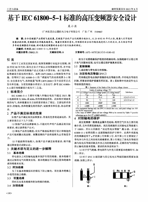
基于IEC61800—5—1标准的高压变频器安全设计
r e l f e c t i o n s u D t o 3 x 、 / x l O O O V  ̄2 - 4 2 V ) .
・
4 对 防触 电的保 护
高压变频器一般都是金属外壳结构 , 利用 空气作为主要 的绝 缘介质 , 且外壳都是接地 的。高压变频器的主回路电压等级都大 于1 0 0 0 V,所 以主回路的 “ 决定性 电压 等级 ”属 D级。在 I E C 6 1 8 0 0 — 5 — 1标准的图 5 一 直接接触的防护示例 中,此类外壳接地
中图分类号 : T M 9 2 1 . 5 1
文献标识码 : B
文章编号 : 1 6 7 2 — 1 6 7 5 ( 2 0 1 3 ) 1 5 — 0 1 8 0 — 0 2
相当于双重绝缘保护程度的绝缘结构 。 加强绝缘可 以通过增
引 言
也可以通过保护隔离来实现。 相 对 于 工 业 发达 国家 来 说 , 我 国变 频 器 行 业 起 步 比较 晚 , 到 大电气 间隙来实现 ,
.
2 产 品 不 满足 标 准 的危 害
如果产 品不满足 相关标准要求, 带来的危害将是深远的。其
主 要 表 现 在 以下 几 个 方 面 :
b . T h e v a l y e o f 4 5 0 0 V M l o w s a l l l o w - v o l t a g e P D S【 0 b e c o v e r e d b y T a b l e 7 ( p o s s i b l e
. 5 直接接触 2 0世纪 9 0年代初 , 国内企业才开始认 识变 频器 的作用 , 并开始 3 人或动物与带 电部分的接触 。 尝试 使 用 , 国 外 的 变频 器 产 品正 式 涌 入 中 国市 场 。 由于 起 步 晚 ,
推荐-IEC61850标准 精品

装置模型结构图
逻辑装置 1
物理…装…置节点
逻辑节点 (x) 数据 (i)
数据1属性1 数据1属性n
数据集 报告/日志
IED
逻辑节点0 数据 (i) 数据集 报告/日志 定值
GOOSE/GSSE
采样传输
服务器
逻 辑 装 置 (x)
物理…装…置节点
取代
逻辑节点 (x)
数据 (i)
控制
数据1属性1 数据1属性n
电力系统通信的多种通信内容 设备的整体逻辑模型采用树形方式,层次
清晰,便于查询 为了规范模型结构,IEC61850标准预先定
义了部分逻辑节点模型
13
IEC61850的简介
XCBR 断路器 XSWI 隔离开关 TCTR 电流互感器 TVTR 电压互感器 SIMG 绝缘介质监视 CSWI 开关控制器 PTOC 带时限过电流 PTRC 保护跳闸条件
IF5:间隔层和过程层之间交换控制数据
IF6:间隔层和站层之间交换控制数据
IF7:站层和远方工程师之间交换数据
IF8:间隔层之间直接快速交换数据,如联锁
IF9:站层之间交换数据
IF10:站层和远方控制中心之间交换数据
9
IEC61850的简介
• 各章节介绍
系
章 节
章 节
装
置
数据模型
系 统
一
章
5 13
lon网
部分厂家用
以太网
各厂商均有
3
IEC61850的目的
• 统一通信标准
目前电站自动化系统通信存在的问题: 通信协议不统一: 103规约 各厂商均有,但各不相同 Modbus 国外厂商采用较多 DNP3.0 美洲厂商采用较多,如:SEL Open2000 南瑞科技 网络103 南瑞继保
IEC 61800-5-1环境测试项目总结
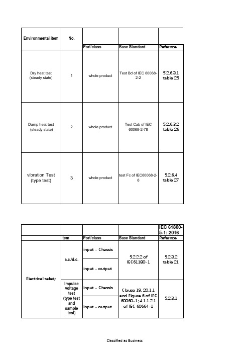
6
table 27
item
Port/class
Base Standard
IEC 61800-
5-1: 2016 Refernce
input - Chassis
a.c./d.c.
input - output
5.2.2.2 of IEC61180-1
5.2.3.2 table 21
Electrical safety
0.075mm amplitude 1g
10 sweep cycles per axis on each of three mutually perpendicular according to manufacturer's specification
5.2.6.2
Refernce 9.4 \ 9.5
Classified as Business
#
IEC 61800-5-1: 2016
requirements
Criterion
Operating conditions Operating at rated conditions
40°C or manufacturer's
Temperature
specified maximum temperature, whichever is
5.2.6.2
Conditions
power supply unconnected
motion
vibration amplitude/acceleration 10Hz<=f<=57Hz 57Hz<=f<=150Hz
vibration duration
detail of mounting
EN61800 标签和说明书的要求
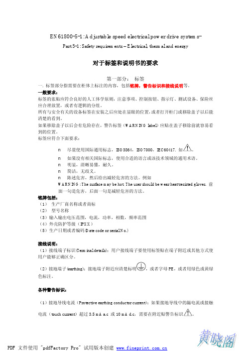
六个方面: 打包和拆包 移动 吊起 安装表面强度 固定 留出足够的操作,调试和维护空间。
(4)电机和驱动设备的要求: 电机的选择: 如果有必要,需要提供和 CDM/BDM 相匹配的电机信息,以及 PWM 输出波形可能会 对电机绝缘造成的影响。 CDM/BDM 的定义如下: BDM(basic drive module):驱动模块(drive module),包含变流部分和对速度,转矩, 电流或电压等参量的控制部分。 CDM(complete drive module):驱动系统(drive system),不包括电机及安装在电机 轴上的传感器,包括但不限于:BDM 及周围扩展的反馈部分和附件。 CDM/BDM/PDS 三者之间的关系如下图所示:
第二部分:说明书
产品应该配备安装手册(Installation manual),使 用手册(User’s manual),维护手册 (Maintennance manual),可以分开编写,也可以编写成一份。
如果编写成一本手册,上面需要包含的内容如下:
1 产品信息的选择(Information for selection)
PDF 文件使用 "pdfFactory Pro" 试用版本创建
集成在电机轴上的传感器要求:对传感器的绝缘要求(防触电保护等级见第三页(保 护等级(protective class)),固体绝缘材料,及爬电距离和空气间隙等要求)。 主要转矩速度: PDS 供应商需要提供所有与电机转速有关的电机信息。
欧洲和美洲的电气防爆

欧洲和美洲的电气防爆简介1欧洲共同体的电气防爆欧洲电工标准化委员会(CENELEC)负责欧洲标准的制订工作,该委员会有18个成员国。
这些国家同时也是国际电工委员会(IEC)的成员国,从数量上占IEC成员国的三分之一,而且许多国家是IEC标准化工作的积极参与者。
国际电工委员会第31技术委员会(IECTC31)是负责爆炸性环境用电气设备方面国际标准的制订工作,为了加快标准的制订工作,使IEC标准从纯技术标准向商业用标准转化,IECTC31提出了与欧洲电工标准化委员会加强合作的战略, IECTC31近年来将欧洲一些标准直接作为IEC标准的CD文件分发各成员国征求意见,然后转化为相应IEC标准。
例如IEC60079-0:1998,IEC60079-11:1999都是由相应的EN标准转化的。
从电气防爆的总体上看,欧洲标准与IEC标准差异不大。
按照欧洲标准规定,欧洲共同体各成员国应在规定的期限内将欧洲标准转化为国家标准。
英国在欧洲标准编号之前冠以英国标准的代号BS,其他内容不变。
例如:BS EN50014BS EN50015……等;联邦德国欧洲标准编号之前冠以德国标准的代号DIN,其他内容不变。
例如:DIN EN50014DIN EN50015 ……等。
1.2防爆电气设备的检验和标志1)按照欧共体防爆框架指针(EC (Ex)Frame Directive)76/117/EEC的规定,符合欧洲防爆标准的防爆电气产品欧共体各成员国应市场准入。
防爆电气产品经型式检验合格和工厂条件检查符合要求,法定的检验单位颁发防爆合格认证证书(EEx Certificate of Conformity ), 产品上允许使用认证标志”EEx”。
标志举例:EEx d ia IIB T42)按照欧洲指针“Directive 94/9/EC of European Parliament and the Council of 23 March 1994 on the approximation of the laws of the Member States concerning equipment and protective systems intended for use in potentially explosive atmospheres”(ATEX 100a) 的规定,防爆电气产品上除了标志防爆类型、类别和温度级别外,还应标志:设备的类别:I ---煤矿用;II—工厂用;允许使用的爆炸危险场所类别: 1---0区;2—1区;3—2区;M1—煤矿1区;M2—煤矿2区;气体或粉尘: G—气体或蒸气环境;D—粉尘环境;例如:ATEX100a 于1996年3月16日正式生效,按照旧的EC制造的防爆电气设备于2003年6月30日停止流通。
欧特顿 Moeller 系列 Rapid Link 速度调节器 198849 产品说明说明书
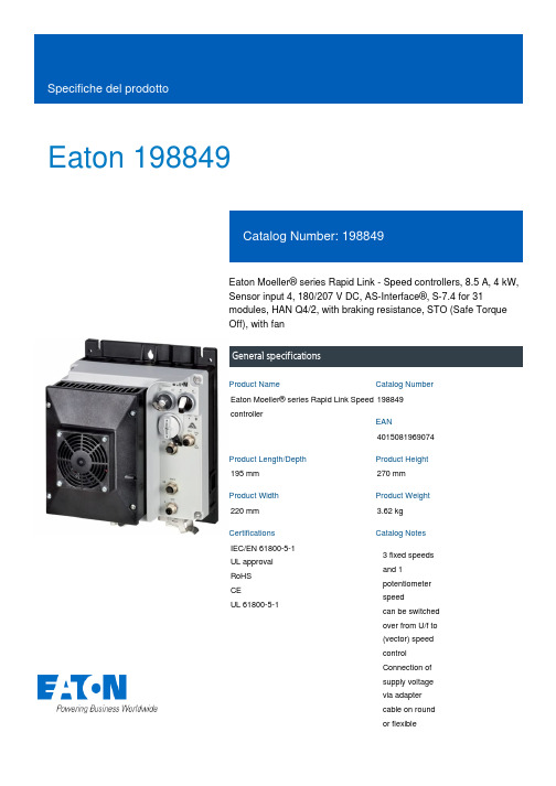
Eaton 198849Eaton Moeller® series Rapid Link - Speed controllers, 8.5 A, 4 kW, Sensor input 4, 180/207 V DC, AS-Interface®, S-7.4 for 31modules, HAN Q4/2, with braking resistance, STO (Safe Torque Off), with fanGeneral specificationsEaton Moeller® series Rapid Link Speed controller1988494015081969074195 mm 270 mm 220 mm 3.62 kg IEC/EN 61800-5-1 UL approval RoHS CE UL 61800-5-1Product NameCatalog NumberEANProduct Length/Depth Product Height Product Width Product Weight Certifications Catalog Notes 3 fixed speeds and 1 potentiometer speedcan be switched over from U/f to (vector) speed control Connection of supply voltage via adapter cable on round or flexibleRASP5-8401A31-4120111S1Parameterization: drivesConnect mobile (App) Parameterization: drivesConnectParameterization: FieldbusDiagnostics and reset on device and via AS-InterfaceInternal and on heat sink, temperature-controlled Fan Parameterization: KeypadControl unitInternal DC linkKey switch position HANDBraking resistanceBreaking resistanceFanSelector switch (Positions: REV - OFF - FWD)PC connectionKey switch position AUTOTwo sensor inputs through M12 sockets (max. 150 mA) for quick stop and interlocked manual operationPTC thermistor monitoringThermo-click with safe isolationIGBT inverterKey switch position OFF/RESETSTO (Safe Torque Off)Brake chopper with braking resistance for dynamic braking1 potentiometer speedFor actuation of motors with mechanical brake3 fixed speeds4-quadrant operation possible IP65NEMA 121st and 2nd environments (according to EN 61800-3)IIISpeed controllerAS-Interface profile cable: S-7.4 for 31 modulesASIC2, C3: depending on the motor cable length, the connected load, and ambient conditions. External radio interference suppression filters (optional) may be necessary.C1: for conducted emissions only2000 VCenter-point earthed star network (TN-S network)Phase-earthed AC supply systems are not permitted.AC voltageVertical15 g, Mechanical, According to IEC/EN 60068-2-27, 11 ms, Half-sinusoidal shock 11 ms, 1000 shocks per shaftResistance: 10 - 150 Hz, Oscillation frequencyResistance: According to IEC/EN 60068-2-6Resistance: 6 Hz, Amplitude 0.15 mmResistance: 57 Hz, Amplitude transition frequency on accelerationModel CodeFeatures Fitted with:FunctionsDegree of protectionElectromagnetic compatibilityOvervoltage categoryProduct categoryProtocolRadio interference classRated impulse withstand voltage (Uimp)System configuration typeMounting positionShock resistanceVibrationbusbar junctionDiagnostics andreset on deviceand via AS-Interfaceintegrated PTCthermistormonitoring andThermoclick withsafe isolationoptional: 4sensor inputswith M12-Yadapter forswitchover tocreep speedoptional: Fasterstop if external24 V failsTwo sensorinputs throughM12 sockets(max. 150 mA)for quick stopand interlockedmanualoperationwith AUTO -OFF/RESET -HAND keyswitcheswith selectorswitch REV -OFF - FWDAbove 1000 m with 1 % performance reduction per 100 m Max. 2000 m-10 °C40 °C-40 °C70 °C< 95 %, no condensationIn accordance with IEC/EN 501780.8 - 8.5 A, motor, main circuit Adjustable, motor, main circuit< 10 ms, Off-delay< 10 ms, On-delay98 % (η)7.8 A3.5 mA120 %Maximum of one time every 60 seconds380 V480 V380 - 480 V (-10 %/+10 %, at 50/60 Hz)Synchronous reluctance motorsU/f controlBLDC motorsSensorless vector control (SLV)PM and LSPM motors0 Hz500 HzAt 40 °CFor 60 s every 600 s12.7 AAltitudeAmbient operating temperature - min Ambient operating temperature - max Ambient storage temperature - min Ambient storage temperature - max Climatic proofing Current limitationDelay timeEfficiencyInput current ILN at 150% overload Leakage current at ground IPE - max Mains current distortionMains switch-on frequencyMains voltage - minMains voltage - maxMains voltage toleranceOperating modeOutput frequency - minOutput frequency - maxOverload currentOverload current IL at 150% overload45 Hz66 Hz4 kW400 V AC, 3-phase 480 V AC, 3-phase 0.1 Hz (Frequency resolution, setpoint value)200 %, IH, max. starting current (High Overload), For 2 seconds every 20 seconds, Power section 50/60 Hz8 kHz, 4 - 32 kHz adjustable, fPWM, Power section, Main circuit Center-point earthed star network (TN-S network) Phase-earthed AC supply systems are not permitted. AC voltage5 HP≤ 0.6 A (max. 6 A for 120 ms), Actuator for external motor brake Adjustable to 100 % (I/Ie), DC - Main circuit ≤ 30 % (I/Ie)280/207 V DC -15 % / +10 %, Actuator for external motor brake 765 VDC10 kAType 1 coordination via the power bus' feeder unit, Main circuit180/207 V DC (external brake 50/60 Hz)24 V DC (-15 %/+20 %, external via AS-Interface® plug)AS-Interface Plug type: HAN Q4/2Max. total power consumption from AS-Interface® power supply unit (30 V): 190 mANumber of slave addresses: 31 (AS-Interface®) Specification: S-7.4 (AS-Interface®)Rated frequency - min Rated frequency - max Rated operational power at 380/400 V, 50 Hz, 3-phase Rated operational voltage ResolutionStarting current - maxSupply frequency Switching frequencySystem configuration typeAssigned motor power at 460/480 V, 60 Hz, 3-phase Braking currentBraking torqueBraking voltageSwitch-on threshold for the braking transistor Rated conditional short-circuit current (Iq)Short-circuit protection (external output circuits)Rated control voltage (Uc)Communication interface ConnectionInterfacesC2 ≤ 5 m, maximum motor cable length C3 ≤ 25 m, maximum motor cable length C1 ≤ 1 m, maximum motor cable length Meets the product standard's requirements.Meets the product standard's requirements.Meets the product standard's requirements.Meets the product standard's requirements.Meets the product standard's requirements.Does not apply, since the entire switchgear needs to be evaluated.Does not apply, since the entire switchgear needs to be evaluated.Meets the product standard's requirements.Does not apply, since the entire switchgear needs to be evaluated.Meets the product standard's requirements.Does not apply, since the entire switchgear needs to be evaluated.Does not apply, since the entire switchgear needs to be evaluated.Is the panel builder's responsibility.Is the panel builder's responsibility.Is the panel builder's responsibility.Is the panel builder's responsibility.Cable length10.2.2 Corrosion resistance10.2.3.1 Verification of thermal stability of enclosures10.2.3.2 Verification of resistance of insulating materials tonormal heat10.2.3.3 Resist. of insul. mat. to abnormal heat/fire by internalelect. effects10.2.4 Resistance to ultra-violet (UV) radiation10.2.5 Lifting10.2.6 Mechanical impact10.2.7 Inscriptions10.3 Degree of protection of assemblies10.4 Clearances and creepage distances10.5 Protection against electric shock10.6 Incorporation of switching devices and components10.7 Internal electrical circuits and connections10.8 Connections for external conductors10.9.2 Power-frequency electric strength10.9.3 Impulse withstand voltageIs the panel builder's responsibility.The panel builder is responsible for the temperature rise calculation. Eaton will provide heat dissipation data for the devices.Is the panel builder's responsibility. The specifications for the switchgear must be observed.Is the panel builder's responsibility. The specifications for the switchgear must be observed.The device meets the requirements, provided the information in the instruction leaflet (IL) is observed.Rapid Link 5 - brochureDA-SW-USB Driver DX-COM-STICK3-KITDA-SW-drivesConnect - InstallationshilfeDA-SW-USB Driver PC Cable DX-CBL-PC-1M5DA-SW-drivesConnectDA-SW-drivesConnect - installation helpDA-SW-Driver DX-CBL-PC-3M0Material handling applications - airports, warehouses and intra-logisticseaton-bus-adapter-rapidlink-speed-controller-dimensions-004.eps eaton-bus-adapter-rapidlink-speed-controller-dimensions-002.eps eaton-bus-adapter-rapidlink-speed-controller-dimensions-003.eps eaton-bus-adapter-rapidlink-speed-controller-dimensions.epsETN.RASP5-8401A31-4120111S1.edzIL034085ZUrasp5_v28.stpramo5_v28.dwgGeneration change RAMO4 to RAMO5Generation change from RA-SP to RASP 4.0Generation change from RA-MO to RAMO 4.0Generation Change RASP4 to RASP5Configuration to Rockwell PLC for Rapid LinkGeneration Change RA-SP to RASP5DA-DC-00004612.pdfDA-DC-00003964.pdfDA-DC-00004184.pdfDA-DC-00004613.pdf10.9.4 Testing of enclosures made of insulating material10.10 Temperature rise10.11 Short-circuit rating10.12 Electromagnetic compatibility 10.13 Mechanical function BrochureDisegnieCAD modelIstruzioni di installazione mCAD modelNote per l'applicazione Report di certificazioneEaton Corporation plc Eaton House30 Pembroke Road Dublin 4, Ireland © 2023 Eaton. Tutti i diritti riservati. Eaton is a registered trademark.All other trademarks areproperty of their respectiveowners./socialmedia。
IEC61850介绍

XSWI
过流保护 PTOC
开关/刀闸 遥控
CSWI
实际装置
CPU3
开关控制 开关位置
1850标准
IEC 61850 概述 IEC 61850 功能演示 IEC 61850 简介 IEC 61850 在RCS9700中的应用
概述
IEC61850是新一代的变电站自动化系统的国际标准 国际电工委员会(IEC)TC57工作组制定的《变电站 通信网络和系统》系列标准,是基于网络通信平台 的变电站自动化系统唯一的国际标准
•1) 站控计算机. •2) 同期装置. •3) 距离保护+过流保护 •4) 开关单元控制器 •5) 电流互感器 •6) 电压互感器 •7) 母线电压互感器.
物理映射到逻辑
保护功能 差动保护
PDIF
虚拟装置
测量功能 控制功能
计量类测量 开关位置
MMTR
XCBR
距离保护 PDIS
相序测量 刀闸位置
MSQI
智能化一次设备和数字式变电站要求变电 站自动化采用IEC61850标准。
概述
IEC61850是至今为止最为完善的变电站自动 化标准
规范二次智能装置的通信模型、通信接口, 而且还定义了数字式CT、PT、智能式开关 等一次设备的通信模型、通信接口。
采用IEC61850国际标准可以大大提高变电 站自动化技术水平、提高变电站自动化安全 稳定运行水平,节约开发、验收、维护的人 力物力,实现完全互操作。
与其他国际标准相比, IEC61850不仅局限 于单纯的通信规约, 而是(数字)化变电 站自动化系统的标准,它指导了变电站 自动化的设计、开发、工程、维护等各 个领域。
概述
IEC61850标准通过对变电站自动化系统中 的对象统一建模,采用面向对象技术和 独立于网络结构的抽象通信服务接口, 增强了设备之间的互操作性,可以在不 同厂家的设备之间实现无缝连接。
IEC 61800-5-1 Information Requirements

84©IEC:200761800-5-1Table 28 Information requirementsLocation a, b, c Technical subclauseInformation Subclausereference 12345referenceFor selection 6.2Manufacturer s name and catalogue number 6.2X X X X XVoltage rating 6.2X X X XCurrent rating 6.2X X XPower rating 6.2X X XShort-circuit ratings 6.2X 4.3.9IP rating 6.2 X X X 4.3.3.3, 4.3.7.1Reference to standards 6.2XDate code or serial number 6.2XReference to instructions 6.2X X XFor installation and commissioning 6.3Dimensions (SI units) 6.3.2 X XMass (SI units) 6.3.2 X X XMounting details (SI units) 6.3.2 X XOperating and storage environments 6.3.3 X XEnclosure details 6.3.3 X X 4.3.3.3, 4.3.7.1, 4.4.3Handling requirements 6.3.4 X X XMotor requirements 6.3.5 X X XInterconnection and wiring diagrams 6.3.6.2 X XCable requirements 6.3.6.3 X X 4.3.8Terminal details 6.3.6.4 X X X 4.3.8.8.2Protection requirements 6.3.6.5 X X 4.3Earthing 6.3.6.6 X X X 4.3.5.3, 4.3.5.3.2, 4.3.12Protective earthing conductor current 6.3.6.7 X X X 4.3.5.5.2, 4.3.10Special requirements 6.3.6.8 X XSupply overload protection 6.3.7 X X XMotor overload protection 6.3.8 X XCommissioning information 6.3.9XFor use 6.4General 6.4.1 X XAdjustment 6.4.2 X X XLabels, signs, and signals 6.4.3 X X X XFor maintenance 6.5Maintenance procedures 6.5.1 X 4.3.3.3Maintenance schedules 6.5.1 X XSubassembly and component locations 6.5.1 XRepair and replacement procedures 6.5.1 XAdjustment procedures 6.5.1 X X XSpecial tools list 6.5.1 X XCapacitor discharge 6.5.2 X X X 4.3.11Auto restart/bypass 6.5.3 X X XPT/CT connection 6.5.4 X X XOther hazards 6.5.5 X Xa Location: 1. On product (see 6.4.3); 2. On packaging; 3. In installation manual; 4. In user s manual; 5. Inmaintenance manual.b The installation, user s and maintenance manuals may be combined as appropriate and, if acceptable tothe customer, may be supplied in electronic format. When more than one of any product is supplied to asingle customer, it is not necessary to supply a manual with each unit, if acceptable to the customer.c For integrated PDS the information required for location 1 may be combined with the motor nameplateinformation required by IEC 60034-1.。
E530 Servo System User Manual

This guide provides mechanical and electrical installation information for the E530 servo system. For detailed content, please refer to the E530 Servo System User Manual (3AXD50000942800 [EN])。
1. Safety instructionsThis section contains the safety instructions that must be followed when installing, operating and maintaining the servo drive. If ignored, it may result in personal injury or death and damage to the servo drive, motor or drive equipment. Please read this section carefully before operating the servo drive. This section lists only the most important safety information for drive installation, operation and maintenance, For detailed content, please refer to chapter Safety in the E530 Servo System User Manual (3AXD50000942800 [EN]).⏹ 1.1 Unpacking⏹ 1.2 Installation safety instructions⏹ 1.3 Wiring safety instructions⏹ 1.4 Operation safety instructions ⏹ 1.5 Maintenance safety instructions2. Product overview⏹ 2.1 Drive componentsAs shown in the figure below, the package ofthe drive contains the followingcomponents. Make sure that all the itemsare present and there are no signs ofdamage.⏹ 2.2 Drive labelsThe drive has two labels:• Model information label in front of the drive• Type designation label on the left side of the drive.⏹⏹ 2.4 System structureThis section introduces the connection of the components in the servo drivesystem, which helps the users quickly understand the E530 series servoproducts. Different frame sizes have different power input and are used withdifferent types of motors. Taking F2 and F4 as examples, the typical systemconnection diagram is shown below.Frame size F2Frame size F4⏹ 2.5 Technical data⏹ 2.6 Drive and motor configuration table⏹ 2.7 Cable specificationsTerminal data for power cables ABB Motion E-catalog About this document3AXD50000942787Rev A EN 2022-08-20©2022 ABB All rights reserved.Please check whether the drive type matches the product you ordered.Make sure the specifications (rated power) of the servo drive andmotor are correctly matched. Ignoring this instruction could result inpersonal injury or death or equipment damage.•Please keep the servo drive in the package before installation. Afterunpacking, keep away from dust, debris and moisture.•Use required personal protective equipment: safety shoes with metal toecaps, goggles, protective gloves and long sleeves, etc, as some parts havesharp edges.•Do not install the servo drive in the environment of high temperature,humidity, corrosive gas, flammable and explosive gas, metal dust, oil mist,water vapor, etc.•Do not install the servo drive in a place with continuous vibration or physicalshock, strong electromagnetic interference, or sudden temperature change.•Do not fasten the servo drive by riveting or welding.•When installing, make sure that debris from drilling and grinding does notenter the servo drive. Conductive debris inside the servo drive may causedamage or malfunction of the device.•Install the mounting plate as vertical as possible and strong enough tosupport the weight of the drive. Metal materials are recommended as thematerial for mounting plate. The floor below the installation location shouldbe made of flame retardant material.•The installation site should be well ventilated or have adequate coolingfacilities to remove the heat emitted by the drive.•Verify that all mounting frames are properly grounded and that contactsurfaces are free of paint.Note! Electrical design and installation must comply with local laws andregulations. ABB is not responsible for installations that violate locallaws or regulations.•Dangerous voltage charges may remain in the drive even after a poweroutage, so be sure to wait at least 5 minutes after a power outage tomeasure to determine that the device is de-energized before performing anywiring or inspections.•Avoid touching any other live parts in the workplace. Take specialprecautions when working near exposed conductors.•Make sure that the servo system is safely grounded in accordance with localregulations to ensure the reliability of the equipment.•Do not connect the servo drive to a voltage higher than that marked on themodel label, it can cause damage to internal components.•Do not solder exposed wires. Solder will shrink over time, potentially causingloose connections. Use crimp connections whenever possible.•The AC power supply must be fused.system.•Adjust the limit value (speed, current, etc.) of the servo drive, and make surethat the motor and all driven equipment can run within the limit range.•Be careful with hot surfaces. During use, the surfaces of servo systemcomponents (such as reactors or braking resistors) can become very hot andremain hot for a period of time after the power is disconnected. Brakingresistors may generate enough heat to ignite flammable materials. To avoidfire hazard, keep all flammable materials and flammable substances awayfrom the braking resistor.—ABB Servo ProductE530 Servo DriveQuick installation guide•Make sure that the safety circuits (eg emergency stop) connected to theservo drive are verified.•The servo drive is allowed to power on up to 5 times every 10 minutes. Toofrequent power-ups can damage the DC capacitor charging circuit.•Before using the automatic fault reset or automatic restart function of theservo drive, make sure that no dangerous situation occurs. After a fault orpower interruption, the servo drive automatically resets and continues to runthrough these functions. If these functions are used, they must be clearlymarked on the equipment as specified in IEC/EN 61800-5-1, clause 6.5.3, eg"This equipment will start up automatically".electric shock.•The fan and other components of the servo drive are replaced andmaintained by ABB or an authorized service center, Users are not allowed todisassemble them.•Servo drives are not field repairable. Do not repair a malfunctioning servodrive. If the servo drive fails, please contact your local ABB office orauthorized service center.No.Description1Servo drive2Quick installation guide(ZH & EN)1Drive type2Manufacturer information3Nominal ratings4Degree of protection5Certification markings6QR code (Material number + serial number)7Drive type8Serial number9QR code (Product web site)10S/N: Serial number of format MYYWWXXXXX, whereM: Manufacturer designationYY: Year of manufacture: 20, 21, 22, …for year 2020, 2021, 2022…WW: Week of manufacture:01,02,03,…for week 1, week 2, week 3...XXXXX: Running item number that starts each week from 00001.No.F2,F3F41Modbus TCP communication andcommissioning softwareconnection port (RJ 45)Modbus TCP communication andcommissioning softwareconnection port (RJ 45)2Five digit seven segment LEDdisplayFive digit seven segment LEDdisplay3Display operation buttons Display operation buttons4Control signal connector Control signal connector5Encoder connector Encoder connector6Input power and brake resistorconnection terminalsInput power, motor power andbrake resistor connection terminals7Motor power connection terminals Type designation label8Type designation label Grounding screws9Grounding screws Short-circuit connector10-BaffeS/N W222312345Made in ChinaS/N W222312345F41Power cable, 1-phase 4Control cable(44-pin D-type connector)2Motor cables 5Communication cable (RJ45)3Encoder cable(1394 connector)6System grounding busbar1Power cable, 1-phase or 3-phase4Control cable(44-pin D-type connector)2Motor cables 5Communication cable (RJ45)3Encoder cable(1394 connector)6System grounding busbarTypeFramesizeInput rating Output ratingI1N I2N I2max P NA A A kW200W~1kW, 1-phase, UN=200...240V. 1.5kW/2kW1-phase or 3-phase, UN=200 (240V)E530-PT0S-0KW2-1F2 2.5 1.50 4.500.20E530-PT0S-0KW4-1F2 4.7 2.908.700.40E530-PT0S-0KW8-1F38.5 5.0015.000.75E530-PT0S-1KW0-1F310.0 5.3516.05 1.00E530-PT0S-1KW5-2F4 6.47.6022.80 1.50E530-PT0S-2KW0-2F48.010.1030.30 2.00Rated power E530 servo drive type DSM motor type0.05 kWE530-PT0S-0KW2-1DSM04L-0KWA-302-XXXX00.1 kW DSM04L-0KW1-302-XXXX00.2 kW DSM06L-0KW2-302-XXXX00.4 kW E530-PT0S-0KW4-1DSM06L-0KW4-302-XXXX00.75 kW E530-PT0S-0KW8-1DSM08L-0KW8-302-XXXX0DSM08M-0KW8-302-XXXX01 kW E530-PT0S-1KW0-1DSM13M-1KW0-202-XXXX01.5 kW E530-PT0S-1KW5-2DSM13M-1KW5-202-XXXX02.0 kW E530-PT0S-2KW0-2DSM13M-2KW0-202-XXXX0TypeL1, L2, L3, P, R, C, N terminalsMin(solid/stranded)Max(solid/stranded)Tighteningtorquemm2AWG mm2AWG N·m ldf·inE530-PT0S-0KW2-10.7518 2.513--E530-PT0S-0KW4-10.7518 2.513--E530-PT0S-0KW8-1 1.5016 2.513--E530-PT0S-1KW0-1 1.5016 2.513--E530-PT0S-1KW5-2 2.513 6.010 1.4±0.212.39±1.8E530-PT0S-2KW0-2 2.513 6.010 1.4±0.212.39±1.8TypeU, V, W terminalsMin(solid/stranded)Max(solid/stranded)Tighteningtorquemm2AWG mm2AWG N·m ldf·inE530-PT0S-0KW2-10.7518 2.513--E530-PT0S-0KW4-10.7518 2.513--E530-PT0S-0KW8-10.7518 2.513--E530-PT0S-1KW0-10.7518 2.513--E530-PT0S-1KW5-2 2.014 6.010 1.4±0.212.39±1.8E530-PT0S-2KW0-2 2.014 6.010 1.4±0.212.39±1.8220V AC powerBreakerFuseFilterPLC controllerExternal computer(Install Servo Composer)AC powerExternal computer(Install Servo Composer)BreakerFusePLC controllerFilterTerminal data for the control cablesEncoder cable terminal data3. Installing the Drive⏹ 3.1 Environmental standards1)For a 1-phase input of a 2kW drive, the output derated to 80%.⏹ 3.2 Installing orientalE530 servo drive only supports vertical mounting. Improper installation ⏹ 3.3 Installing clearanceWhen installing the drive vertically, the thermal dissipation minimum space requirement for is shown as below. Different frame sizes have different free space requirement. Frame sizes F2 and F3 should have a space of more than 10mm reserved on both sides of the drive, and a space of more than 100mm above and below the drive.F2 and F3 support compact installation, but the rated load should be reduced to 80% in this case.For frame size F4, a space of more than 40 mm should be reserved on the left side (connection requirements), and a space of more than 100 mm above and below the drive..⏹ 3.4 Drive weight⏹ 3.5 Drill holes and outline dimensionsF2F3F44. Basic Inspection5. Main circuit wiringBefore wiring the servo drive, perform an insulation check on the power cable according to safety regulations.The main circuit of E530 servo drive is shown in the figure below, which consists of three parts: AC power input, motor power output and external brake resistor.AC power input:• F2/F3:1-phase 220V input,only connect L1/L2,•F4:1-phase or 3-phase 220V input,1-phase input connect any two of L1/L2/L3,2kW 1-phase input derating to 80%.6. Control diagrams⏹200W/400W: 1-phase 220V input, without embedded braking⏹750W/1kW: 1-phase 220V input, with embedded braking resistor1.5kW/2kW:1-phase or 3-phase 220V input, with embedded7. MarkingsApplicable certification marks are displayed on the type label of thedrive.Type44 core I/O signal wireCable sizemm 2AWG 1-phase/3-phase, U N = 200…240 VE530-PT0S-0KW2-10.09 ~ 0.528 ~ 20E530-PT0S-0KW4-10.09 ~ 0.528 ~ 20E530-PT0S-0KW8-10.09 ~ 0.528 ~ 20E530-PT0S-1KW0-10.09 ~ 0.528 ~ 20E530-PT0S-1KW5-20.09 ~ 0.528 ~ 20E530-PT0S-2KW0-20.09 ~ 0.528 ~ 20Motor type Flange size (mm)Cable cross-sectionof coresLengthDSM04L-0KWA-3024024AWG/26AWG3/5/10/15/20/30 mDSM04L-0KW1-30240DSM06L-0KW2-30260DSM06L-0KW4-30260DSM08L-0KW8-30280DSM08M-0KW8-30280DSM13M-1KW0-20213024AWG/26AWG DSM13M-1KW5-202130DSM13M-2KW0-202130Parameter DescriptionDrive type E530-PT0S-xKWx-xMain power supply0.2~1.0kW:1-phase 200~240V,-15%~10%;1.5kW~2kW 1):1-phase AC/3-phase200~240V,-15%~10%; 50/60Hz,- 5%~5%Frame size F2: 0.2kW / 0.4kW F3: 0.75kW / 1.0kW F4: 1.5 kW / 2.0kWOperating environmentIndoor (no direct sunlight), no corrosive gas, flammable gas, oil gas or dust.Operating temperature (°C)Operation temperature:0°C~55°C; (0°C~45°C, no derating; 45°C~55°C derating as 80%, the derating is 2% for every 1°C increasing), see the figure below:Storage temperature (°C)-20°C ~ +65°C Transport temperature (°C)-20°C ~ +65°CRelative humidity (RH)0 ~ 90% (on-condensing)Installation altitude (m)<1000 m (without derating); 1000 m - 2000 m (with derating), the derating is 1% for every 1°C increasing.Sine Vibration (IEC 60721-3-3)OperationTest based on IEC 60721-3-3.mechanical condition: 3M4 class,2…9 Hz, 3.0 mm,9…200 Hz, 10 m/s2Frame size Net weight Gross weight Package net weight kg lb kg lb kg lb F20.75 1.66 1.04 2.280.260.58F3 1.10 2.42 1.43 3.160.310.69F41.653.642.044.510.390.86ItemsGeneral inspectionRegularly check the servo drive's screws, motor shafts, terminals, and connections to the mechanical system for looseness and eccentricity, and tighten the screws if necessary, as they may loosen due to vibration and temperature changes.Make sure that oil, water, metal dust or any foreign objects do not fall into the servo drive, motor, control panel or fan as these can cause damage to the equipment.Inspection before operationTo avoid electric shock, be sure to connect the ground terminal of the servo drive to the ground protection terminal of the control cabinet.Before making any connections, disconnect the power and wait 5 minutes for the capacitors to discharge or use a suitable discharge device.Make sure all terminals are properly insulated.Make sure all systems are wired correctly, otherwise equipment damage and malfunction may result.Visually inspect to make sure there are no unused screws, metal bars, or any conductive or flammable material inside the drive.Never put flammable objects on the servo drive or close to the external regenerative braking resistor.Make sure the emergency stop switch is off.If an electromagnetic brake is used, please make sure that its circuit for cutting off the power is normal and effective.If necessary, use appropriate electronic filters to eliminate electromagnetic interference.Make sure the external voltage to the drive is correct.Maindimensions/ mmW H1H2H3D1D2Screw Screw torque Drill hole/mm 4020217570150802 / pcsM5 , 3.0/ N.mL1: 190L2: 20Front viewFront view Maindimensions/ mmW H1H2H3D1D2Screw Screw torque Drill hole/mm 8020217570175804 / pcsM5 , 3.0/ N.mL1: 190L2: 60Inspection during operationWhen the motor is running, pay close attention to the encoder cable connections for damage, wear, or overextending.Check for abnormal vibrations and sounds during operation.Make sure all parameters are set correctly.When resetting the parameters, make sure that the drive is in the servo stop state. Otherwise, malfunction may result.Ensure correct operation when using relays.Check the power indicator and LED display for any abnormality.1Circuit breaker43-phase/1-phase AC input terminals2Fuse 5Grounding screw3Filter 6System grounding busbarCE UKCA EIP green WEEEPEground point。
电梯电气安全要求

● GB 7588-2003《电梯制造与安装安全规范》 ● GB 16899-2011《自动扶梯和自动人行道的制造与安装安全规范》 ● GB 25194-2010《杂物电梯制造与安装安全规范》 ● GB 50068-2008《电梯安装工程施工质量验收规范》 ● GB 50182-2009《电梯安装工程施工质量验收规范》 ● GB 50183-2009《电梯安装工程施工质量验收规范》 ● GB 50184-2008《电梯安装工程施工质量验收规范》 ● GB 50185-2008《电梯安装工程施工质量验收规范》 ● GB 50186-2008《电梯安装工程施工质量验收规范》 ● GB 50187-2008《电梯安装工程施工质量验收规范》
行业标准
✓ 国家标准:GB7588-2003 《电梯制造与安装安全规范》
✓ 国际标准:IEC61800《电 梯安全标准》
✓ 行业标准:GB/T100582009《电梯电气设备安全要 求》
12
34
✓ 地方标准:各地方政府制定的 电梯电气安全标准,如北京市 地方标准DB11/T 1005-2015 《电梯电气安全要求》
准
06
IEC 61800-56:2016 电梯电 气设备安全标
准
07
IEC 61800-57:2016 电梯电 气设备安全标
准
08
IEC 61800-58:2016 电梯电 气设备安全标
准
09
IEC 61800-59:2016 电梯电 气设备安全标
准
10
IEC 61800-510:2016 电梯 电气设备安全
4
定期检查
A
检查周期:每月至少进 行一次全面检查
B
检查内容:电气设备、 线路、开关、插座等
欧洲车载充电机 技术标准

欧洲车载充电机技术标准
欧洲车载充电机的技术标准主要由国际电工委员会(IEC)和欧洲标准化委员会(CEN,CENELEC)制定并推动。
这些标准涵盖了充电设备的安全性、性能、通信协议等方面,以确保电动车充电设备的互操作性和安全性。
以下是一些与欧洲车载充电机相关的技术标准:
1.IEC 61851-1:2017:电动汽车和插座通用充电设备的安全性标
准。
这一标准涵盖了电动车和充电设备的安全要求。
2.IEC 61851-23:2014:电动汽车和插座通用充电设备的交流充
电接口的通信规范。
该标准规定了电动车和充电设备之间的通信协议,以确保正确的充电过程。
3.IEC 62196-1:2014:电动汽车和插座通用充电设备的直流充电
接口的通信规范。
该标准类似于上述标准,但是专注于直流充电接口的通信规范。
4.IEC 61851-24:2014:电动汽车和插座通用充电设备的通信规
范的消息格式。
该标准规定了充电设备和电动车之间的通信所使用的消息格式。
5.EN 50620:2016:充电基础设施的安全规范。
这一欧洲标准适
用于电动车充电设备的安全性。
请注意,这些标准可能会在未来进行更新和修订,而且在我知识截止日期之后可能已经有了新的标准发布。
建议查阅国际电工委员会(IEC)和欧洲标准化委员会(CEN,CENELEC)的官方网站,以获取
最新的技术标准信息。
艾特韦恩 HMX34AG8D022-N 变频驱动器商品说明说明书
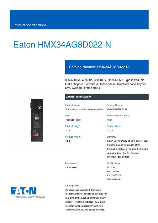
Eaton HMX34AG8D022-NH-Max Drive, 4 hp, 8A, 380-480V, Open NEMA Type 2 IP54, No brake chopper, Software A, Three-phase, Graphical panel keypad, EMC C2 input, Frame size 4General specificationsEaton H-Max variable frequency drive HMX34AG8D022-N 78668551413016 in 10 in7.5 in 16 lbEaton Selling Policy 25-000, one (1) year from the date of installation of the Product or eighteen (18) months from the date of shipment of the Product, whichever occurs first.CE MarkedUL 508C cUL Certified EN 61800-5-1 IEC 61800-5-1All boards are varnished. Corrosion resistant. Battery included in all drives for real-time clock. Keypad kit includes HOA bypass. Keypad kit includes HOA, back reset for Europe application. EMI/RFI filters included. DC link choke included.Product NameCatalog Number UPCProduct Length/Depth Product Height Product Width Product Weight WarrantyCompliances Certifications Catalog NotesEaton Corporation plc Eaton House30 Pembroke Road Dublin 4, Ireland © 2023 Eaton. All Rights Reserved. Eaton is a registered trademark.All other trademarks areproperty of their respective owners./socialmediaFR4EMC C2Three-phase No brake chopper 4 hp Graphical panel Type A Open NEMA 2 IP54380-480 V 8AVariable frequency drive - Product overview Eaton H-Max HVAC Drives Eaton's Volume 6—Solid-State Motor Control HMX_(FR4) AutoCAD 2D Footprint (mm)HMX_(FR4)2D PDFHMX_(FR4) AutoCAD 2D Footprint HMX_(FR4) 3D Inventor HMX_(FR4) 3D Model Xchange HMX_(FR4) 2D Drawing Xchange H-Max Series Adjustable Frequency Drive Installation Manual Eaton Specification Sheet - HMX34AG8D022-NFrame size Input Phase Brake chopper Horsepower Keypad Software EnclosureVoltage rating Amperage Rating BrochuresCatalogsDrawingsInstallation instructionsSpecifications and datasheets。
IEC61800-5-2标准及认证介绍(STO)

IEC61800-5-2标准及认证介绍(STO)根据欧盟新机械指令要求,对于安装在工业机器上的可调速类控制设备,如果参与安全功能的相关控制,就需要满足IEC61800-5-2的标准要求IEC61800-5-2全称为可调速的电气传动系统.第5-2部分:功能安全要求IEC61800-5-2定义了集成安全驱动器的停止安全功能,具体定义如下:●安全力矩停止/STO(Safe Torque Off)●安全停车1/SS1(Safety Stop1)●安全停车2/SS2(Safety Stop2)●安全操作停止/ SOS(safety operation stop)IEC61800-5-2对安全监控功能也进行了相应的定义,如:●加速度安全限制/(SLA) Safely-limited acceleration●步程安全限制/(SLI) Safely-limited increment●运动方向安全限制/(SDI) Safe direction●速度安全限制/(SLS) Safely-limited speed●力矩安全限制/(SLT) Safely-limited torque●位置安全限制/(SLP) Safely-limited position●电动机温度安全限制等/(SMT) Safe motor temperatureIEC61800-5-2标准主要针对变频器,伺服系统,伺服驱动器,安全编/解码器等产品提出了功能安全的要求。
如,安全扭矩停止(STO),SS1,SS2等安全功能,以防止意外的发生。
在业内Vacon,WEG,STOBER,Schmidhauser AG,Mitsubishi,Rockwell,Lenze,Fuji Electric,Festo等国际厂家都由德国莱茵TUV公司颁发了符合IEC61800-5-2的功能安全证书IEC61800-5-2标准目前已经转化成为国标,标准号为GB/T 12668.5.2,国内对口的标委会为全国电力电子学标准化技术委员会调速电气传动系统半导体电力变流器分技术委员会(TC60/SC1)。
艾森 DE1 可变速电机启动器产品说明说明书
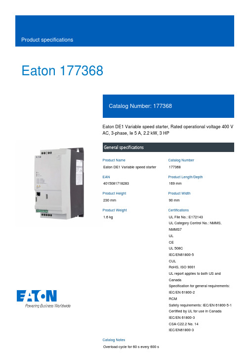
Eaton 177368Eaton DE1 Variable speed starter, Rated operational voltage 400 V AC, 3-phase, Ie 5 A, 2.2 kW, 3 HPGeneral specificationsEaton DE1 Variable speed starter 1773684015081718283169 mm 230 mm 90 mm 1.6 kgUL File No.: E172143UL Category Control No.: NMMS, NMMS7 UL CE UL 508C IEC/EN61800-5 CULRoHS, ISO 9001UL report applies to both US and CanadaSpecification for general requirements: IEC/EN 61800-2 RCMSafety requirements: IEC/EN 61800-5-1 Certified by UL for use in Canada IEC/EN 61800-3 CSA-C22.2 No. 14 IEC/EN61800-3Overload cycle for 60 s every 600 sProduct NameCatalog Number EANProduct Length/Depth Product Height Product Width Product Weight CertificationsCatalog NotesParameterization: drivesConnect Parameterization: drivesConnect mobile (App) Parameterization: Fieldbus Parameterization: KeypadPC connectionPC connection C3 ≤ 25 m, Radio interference level, maximum motor cable lengthC2 ≤ 10 m, Radio interference level, maximum motor cable lengthModbus RTU, built inOP-Bus (RS485), built inIn conjunction with DX-NET-SWD3 SmartWire DT moduleYesIP20NEMA Other1st and 2nd environments (according to EN 61800-3)FS2Variable speed starterFinger and back-of-hand proof, Protection against direct contact (BGV A3, VBG4)MODBUSEtherNet/IPOther bus systemsC2, C3: depending on the motor cable length, the connected load, and ambient conditions. External radio interference suppression filters (optional) may be necessary.Optional external radio interference suppression filter for longer motor cable lengths and for use in different EMC environments15 g, Mechanical, According to IEC/EN 60068-2-27, 11 msBranch circuits, (UL/CSA)FeaturesFitted with: Fitted with:Cable length Communication interface Connection to SmartWire-DT Degree of protection Electromagnetic compatibility Frame sizeProduct category ProtectionProtocolRadio interference classShock resistanceSuitable forVibrationResistance: According to EN 61800-5-1Max. 2000 mAbove 1000 m with 1 % derating per 100 m-10 °C60 °C-10 °C60 °C-40 °C70 °C< 95 average relative humidity (RH), no condensation, nocorrosion7 A< 3.5 mA (AC-operated)< 10 mA (DC-operated)Maximum of one time every 30 seconds 380 V480 VSpeed control with slip compensation U/f control 4.8 A5 A5 A4.8 A3 HP3 HPAltitudeAmbient operating temperature - minAmbient operating temperature - maxAmbient operating temperature at 150% overload - min Ambient operating temperature at 150% overload - max Ambient storage temperature - minAmbient storage temperature - maxClimatic proofingInput current ILN at 150% overload Leakage current at ground IPE - max Mains switch-on frequencyMains voltage - minMains voltage - maxOperating modeOutput frequency - min Assigned motor current IM at 220 - 240 V, 60 Hz, 150% overload Assigned motor current IM at 230 V, 50 Hz, 150% overload Assigned motor current IM at 400 V, 50 Hz, 150% overload Assigned motor current IM at 440 - 480 V, 60 Hz, 150% overload Assigned motor power at 230/240 V, 60 Hz, 1-phaseAssigned motor power at 460/480 V, 60 Hz, 3-phase0 Hz300 Hz400 V AC, 3-phase480 V AC, 3-phase7.5 A10 V DC (Us, max. 0.2 mA)45 Hz66 Hz5 A at 150% overload (at an operating frequency of 16 kHz and an ambient air temperature of +50 °C)2.2 kW400 V AC, 3-phase480 V AC, 3-phase0.025 Hz (Frequency resolution, setpoint value)15 A, UL (Class CC or J), Safety device (fuse or miniature circuit-breaker), Power Wiring200 %, IH, max. starting current (High Overload), For 1.875 seconds every 600 seconds, Power section50/60 Hz16 kHz, 4 - 32 kHz adjustable (audible), fPWM, Power section, Main circuit480 V 3.46 kVA4.16 kVAAdjustable to 100 %, DC - Main circuitMax. 30 % MN, Standard - Main circuit1 (parameterizable, 0 - 10 V DC, 0/4 - 20 mA)4 (parameterizable, 10 - 30 V DC)1 (parameterizable, N/O, 6 A (250 V, AC-1) / 5 A (30 V, DC-1))65 W0 W0 W5 A0 WOperation (with 150 % overload)Output frequency - maxOutput voltage (U2)Overload current IL at 150% overloadRated control supply voltageRated frequency - minRated frequency - maxRated operational current (Ie)Rated operational power at 380/400 V, 50 Hz, 3-phase Rated operational voltageResolutionShort-circuit protection ratingStarting current - maxSupply frequencySwitching frequencyVoltage rating - max Apparent power at 400 VApparent power at 480 VBraking torqueNumber of inputs (analog)Number of inputs (digital)Number of outputs (analog)Number of outputs (digital)Number of relay outputsEquipment heat dissipation, current-dependent PvidHeat dissipation capacity PdissHeat dissipation per pole, current-dependent PvidRated operational current for specified heat dissipation (In) Static heat dissipation, non-current-dependent PvsHeat dissipation detailsMeets the product standard's requirements.Meets the product standard's requirements.Meets the product standard's requirements.Meets the product standard's requirements.Meets the product standard's requirements.Does not apply, since the entire switchgear needs to be evaluated.Does not apply, since the entire switchgear needs to be evaluated.Meets the product standard's requirements.Does not apply, since the entire switchgear needs to be evaluated.Meets the product standard's requirements.Does not apply, since the entire switchgear needs to be evaluated.Does not apply, since the entire switchgear needs to be evaluated.Is the panel builder's responsibility.Is the panel builder's responsibility.Is the panel builder's responsibility.Is the panel builder's responsibility.Set point settingThe OP System Bus - Parameterizing - ControlQuick-Start-Guide DE11 (english)How does the internal motor protection work? Electromagnetic compatibility (EMC)Starting, Stopping and OperationAccess to Parameter Level 2 Parameter Lock Load DefaultFire modeDX-COM-STICK3_ConnectionUpdate DX-COM-STICK3Motor data Motor Protection V/f curves Slip Compensation Quick-Start-Guide DE1 (english)I/O ConfigurationConformal CoatingConnecting drives to generator suppliesNumber 1 in efficiency The easiest way of variable motor speed PowerXL DE1 Variable Speed StarterHVAC, water/wastewater and industrial mediums - brochureDA-SW-drivesConnect USB Driver DX-COM-PCKITDA-SW-drivesConnect - installation helpDA-SW-USB Driver DX-COM-STICK3-KITDA-SW-DE1 ModbusRTU V1_00 LibraryDA-SW-Codesys 2 SWD for DC1 and DE1DA-SW-drivesConnect - InstallationshilfeDA-SW-Driver DX-CBL-PC-3M0DA-SW-Codesys 3 SWD for DC1 and DE1DA-SW-drivesConnectDA-SW-USB Driver PC Cable DX-CBL-PC-1M5Product Range Catalog Drives EngineeringDrives - Product range catalogDA-DC-00004556.pdfDA-DC-00004551.pdf10.2.2 Corrosion resistance10.2.3.1 Verification of thermal stability of enclosures10.2.3.2 Verification of resistance of insulating materials to normal heat10.2.3.3 Resist. of insul. mat. to abnormal heat/fire by internal elect. effects10.2.4 Resistance to ultra-violet (UV) radiation10.2.5 Lifting10.2.6 Mechanical impact10.2.7 Inscriptions10.3 Degree of protection of assemblies10.4 Clearances and creepage distances10.5 Protection against electric shock10.6 Incorporation of switching devices and components10.7 Internal electrical circuits and connections10.8 Connections for external conductors10.9.2 Power-frequency electric strength10.9.3 Impulse withstand voltage Application notes BrochuresCatalogs Certification reports DrawingsEaton Corporation plc Eaton House30 Pembroke Road Dublin 4, Ireland © 2023 Eaton. All Rights Reserved. Eaton is a registered trademark.All other trademarks areproperty of their respectiveowners./socialmediaIs the panel builder's responsibility.The panel builder is responsible for the temperature rise calculation. Eaton will provide heat dissipation data for the devices.Is the panel builder's responsibility. The specifications for the switchgear must be observed.Is the panel builder's responsibility. The specifications for the switchgear must be observed.The device meets the requirements, provided the information in the instruction leaflet (IL) is observed.eaton-frequency-inverter-dimensions-010.eps eaton-frequency-inverter-3d-drawing-018.epsDA-CE-ETN.DE1-345D0NN-N20NIL040005ZUPowerXL DE1 variable speed starterMN040011_ENMZ040046_ENMN040003_ENMN040018_ENDA-CS-de1_fs2_ip20DA-CD-de1_fs2_ip2010.9.4 Testing of enclosures made of insulating material10.10 Temperature rise10.11 Short-circuit rating10.12 Electromagnetic compatibility 10.13 Mechanical function eCAD model Installation instructions Installation videos Manuals and user guidesmCAD model。
电机emc 测试标准

电机emc 测试标准
电机EMC(电磁兼容性)测试是为了确保电机和电子设备在电磁环境中能够正常运行而进行的测试。
这种测试确保设备既不会产生过多的电磁干扰,也不容易受到外部电磁干扰的影响。
以下是电机EMC 测试的主要标准:
* IEC 61800-3:
* IEC(国际电工委员会)发布了关于可变速电机驱动器EMC 的标准,如IEC 61800-3。
这些标准通常适用于调速电机和驱动器系统。
* CISPR 11:
* 适用于家用、商用和轻工业环境的辐射和导引EMC 标准。
* CISPR 14-1:
* 关于电气和电子设备的辐射和导引EMC 标准。
* EN 55011:
* 适用于工业、科学和医疗设备的辐射和导引EMC 标准。
* EN 61800-3:
* 进一步详细规定了可变速电机驱动器EMC 测试的要求。
请注意,确切的测试标准可能会根据电机的类型、应用领域和国家/地区而异。
在进行EMC 测试之前,建议查阅最新的标准文件,以确保符合适用的要求。
此外,考虑到不同国家和地区可能采用不同的标准,最好根据产品的市场定位选择相应的标准。
风力发电机组安全要求(电气与控制)

风力发电机组安全要求(电气与控制)风力发电机组安全要求前言 ........................................................................... ....................................................................... 2 1 范围 ........................................................................... ............................................................... 3 2 引用标准............................................................................ ....................................................... 3 3 基本要素............................................................................ ....................................................... 3 4 外部条件............................................................................ . (3)4.1风力发电机组分级 ........................................................................... ................................. 4 4.2 风况 ........................................................................... .. (4)4.2.1正常风况 ........................................................................... ..................................... 4 4.2.2极端风况 ........................................................................... ..................................... 5 4.3 其他环境条件 ........................................................................... . (8)4.3.1 其他正常环境条件 ........................................................................... .................... 8 4.3.2 其他极端环境条件 ........................................................................... .................... 8 4.4 电网条件 ........................................................................... .............................................. 10 5 结构设计相关安全要求 ........................................................................... .............................. 10 6 控制和保护系统相关安全要 (12)6.1控制和保护系统应满足的基本要求 ........................................................................... ... 12 6.2风力机控制 ........................................................................... ........................................... 13 6.3风力机安全保护 ........................................................................... ................................... 13 6.4监控和安全处理 ........................................................................... ................................... 14 6.5控制和保护的系统功能要求 ........................................................................... ............... 15 7 电气系统相关安全要求 ........................................................................... (16)7.1风力发电机组电气系统的一般要求 ........................................................................... ... 16 7.2电气接线和电气连接相关要求 ........................................................................... ........... 16 7.3电气系统的保护相关要求 ........................................................................... ................... 17 7.4接地系统 ........................................................................... ............................................... 17 7.5电磁兼容性相关要求 ........................................................................... ........................... 17 7.6降低设备干扰效应相关措施 ........................................................................... ............... 17 7.7控制电路相关要求 ........................................................................... ............................... 18 7.8测量和指示电路相关要求 ........................................................................... ................... 18 7.9电缆的相关要求 ........................................................................... ................................... 18 7.10自励 ........................................................................... ..................................................... 19 7.11过压保护 ........................................................................... ............................................. 19 7.12谐波和功率调节装......................... 19 7.13分离装置 ........................................................................... ............................................. 19 8 防雷系统的相关安全要求 ........................................................................... .. (19)8.1 雷电放电的分类及其防护 ........................................................................... .................. 19 8.2 防雷区的划分 ........................................................................... ...................................... 20 8.3 避雷器种类及其接线方式 ........................................................................... .................. 20 8.4 接地分类及相关要求 ........................................................................... ........................ 20 8.5 WTGS的防雷等级要求 ........................................................................... ......................... 21 9 运行和维护............................................................................ . (21)前言本文概述了风力发电机组(WTGS)最低的安全要求,但并不能作为完整的设计规范或结构设计手册来使用。
- 1、下载文档前请自行甄别文档内容的完整性,平台不提供额外的编辑、内容补充、找答案等附加服务。
- 2、"仅部分预览"的文档,不可在线预览部分如存在完整性等问题,可反馈申请退款(可完整预览的文档不适用该条件!)。
- 3、如文档侵犯您的权益,请联系客服反馈,我们会尽快为您处理(人工客服工作时间:9:00-18:30)。
TÜ V SÜ D Group
Department name
20 November 2008
How to determine system voltage- IEC 61800-5-1
4.3.6.2.1
rtment name
20 November 2008
How to determine system voltage- derived from IEC 60664-1
2 550 / 1 800
IT (not corner earthed) AC 380-400 2000 230 III
IT (corner earthed) AC 380-400 2000 400 III
Rated voltage (V) AC 380-420 Max. altitude (m) System voltage Overvoltage 5000 250 III B/S Rated Impulse voltage (kV) Temporary overvoltage (V) Clearance (mm) Test impulse voltage for clearance (kV) A.C. or d.c. voltage test
TN-S, TN-C, TN-CS, TT (not corner earthed) 1150/7,5kHz cl.: 3,0/5,5 850/7,5kHz Cr.: 4,25/8,5 <420
TN-S, TT (corner earthed)
TN-S, TN-C, TN-CS, TT (not corner earthed) 250
How to determine insulation diagram? Link to User access
TÜ V SÜ D Group
Department name
20 November 2008
selection and information for clearance
Power systems TN-S, TN-C, TNCS, TT (not corner earthed) TN-S, TT (corner TN-C (middle earthed) point earthed AC 380-400 2000 400 III D/R 6000 by 1,6 5,5 B/S 6000
Successful product safety design for equipments covered by IEC/EN 61800-5-1 Electrical Hazard Section
presented by Zhengdong Ma, Medical group leader TUV SUD Jiangsu
Working voltage measurements for Cr. and Cl.
TÜ V SÜ D Group
Department name
20 November 2008
Working voltage measurements for Cr. and Cl.
Worst case: sum of primary + secondary
TÜ V SÜ D Group
Department name
20 November 2008
Working voltage
Reference voltage: minimum mains voltage, and Measured voltage Device being in normal, expected and foreseen use , by measurement of reference voltage (RMS) between components: transformers, optical isolators....:(when using 2 channel differential oscilloscope: Ref, 0V and Neutral connected to earth).
Verdict (P /F)
Measured cr. (mm) Remarks
TÜ V SÜ D Group
Department name
20 November 2008
Electrical Hazard- Design/testing input
TABLE: Solid insulation, Impulse voltage test, A.C. or d.c. voltage test, Partial discharge test
Condition # (standby,10Hz ON with motor, 10Hz ON without motor, 60Hz ON with motor, breaking switch ON, etc With DC link voltage on max. allowable value U peak (V) measured U r.m.s. (V) measured U peak (V) Mains U r.m.s. Mains
TN-S, TT (corner earthed) 400
Working voltage BI/DI
<840
For cr.: assume pollution II, PWBs insulation with controlled tolerances
TÜ V SÜ D Group
Department name
by 1,6
4000
2 120 / 1 500
3,0;<3, 0
1500 AC
3000 AC
1800 AC
3600 AC
Department name 20 November 2008
Working voltage measurements for Cr. and Cl.
TABLE: Working voltage measurements for clearance and creepage distances
Test voltage applied between/at: DTI (mm) Impulse test (kV, circuit) Electric strength test (V a.c., V d.c.) 3600 Partial discharge test (V) 1150 Result
1/RI
optocoupler
1,0
8000
P (as evidenced by ecrt.)
1/RI
transformer
IPM Insulation film over braking resistor
Department name 20 November 2008
5/BI 5/BI
TÜ V SÜ D Group
Area Insulation (FI/BI/SI/DI/RI) Test voltage applied between/at: DTI (mm) Impulse test (kV, circuit) Electric strength test (V a.c., V d.c.)
Verdict (P or F)
TÜ V SÜ D Group
AC 380-400 4000 400 II
D/R 8000
by 1,6
B/S 4000
2 550 / 1 800
D/R 6000
by 1,6
B/S 4000
2 550 / 1 800
D/R 6000
by 1,6
B/S 6000
2 550 / 1 800
D/R 8000
20 November 2008
selection and information for Solid insulation
4.3.6.8 5.2.3.1 5.2.3.2 5.2.3.3
Area
TABLE: Solid insulation, Impulse voltage test, A.C. or d.c. voltage test, Partial discharge test
Partial discharge test (V)
TÜ V SÜ D Group
Department name
20 November 2008
Electric shock hazards--- Design/testing input
To finish the above table and serves it as design input, also testing input! Then how to finish the above table? First, try to prepare a correct insulation blocking diagram with graphical representation of equipment insulation barriers, protective impedance and protective earthing. A clear insulation diagram will tell your correct isolation area and required insulation barrier. Based on which, we may finish the above table, columns 1 and 2
TÜ V SÜ D Group
Department name
20 November 2008
How to determine system voltage- back to the above table
