开欧客V6中文说明书
V6+说明书
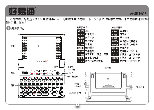
主機提供可拆卸充電鋰電池。
置入:沿電池蓋上箭頭方向,推動並 打開電池蓋,再按右圖中的箭 主機附帶5V /500mA 插入電源插座,另一端插入主機 用整流器對電池進行充電時,電池充飽時間約為 請將本機專用USB 線一端與 另一端插入本機 當使用USB 線對電池進行充電時,電 池充飽時間約為配備件選配件耳機電池適配器USB 線電腦詞典主機鍵關閉主機。
主機未關機前請勿隨意插拔卡片或做其他違法操作,以免引起主機異常或資料丟失。
屏幕操作主機提供可觸控屏幕,支持各種觸控操作。
請使用主機專用手寫筆實現這些操作。
標示直接按部分功能按鍵,即可實現 按鍵上標識的功能:鍵搭配使用,搭配按鍵的操作步驟為:先按再按功能鍵。
以上描述的兩種功能鍵操作方法,請對應參考使用。
˙ 菜單瀏覽 按翻頁鍵翻頁瀏覽菜單中的各功能選項。
當菜單有翻頁標識(箭頭類標識)時,可點擊翻頁標識瀏覽菜單。
˙ 選擇選項按主機上下鍵逐行滾動瀏覽資料。
按主機翻頁鍵翻頁瀏覽主機資料。
當屏幕中出現滾動條時,可用筆拖動滾動條進行資料瀏覽。
輸入區 主機默認光標閃爍處為資料輸入區,可按方向鍵和 或直接點選移動光標選擇輸入區。
輸入法 主機提供多種方式的多國語輸入法,先按 [SPACE]鍵,或點選標識打開菜單選擇輸入法。
菜單操作資料瀏覽資料輸入˙ 點圖示,開啟部分語言手寫輸入法。
˙ 點/// ,可切換中文/英文/日文/韓文手寫輸入。
˙ 點,切換為各輸入法對應之軟鍵盤。
˙ 點,開啟符號軟鍵盤。
˙ 點,關閉手寫窗口,返回鍵盤輸入狀態。
˙ 點//,切換單框手寫/多框手寫/全屏幕手寫功能。
˙ 全屏幕和單框手寫時,點/進行手寫輸入單字辨識/多字辨識設定。
其他功能鍵簡介輸出符號輸出數字例與配,實現按鍵上紅字部份功能現部選字區聯想區選字區聯想區符號軟鍵盤對不易掌握或重要的詞彙、句子和會話,可按“複習測驗”、“背單詞”及翻譯記錄使用。
˙ 詞典/會話/多媒體搜索 可在詞典、會話和多媒体功能畫面輸入詞彙或標示詞彙進行查詢。
V6自动检测控制仪基本操作说明书

PDF 文件使用 "pdfFactory Pro" 试用版本创建
概要
本仪器(PULCOM V6)是控制机床用的电动测量控制仪。本产品具 有模拟表头,对应于加工后测量的形式,其功能可以对应加工后的各种尺 寸的测量。把加工后各种工件的尺寸,使用电动传感器或气动量仪(通过 气动测头和 AE 转换器)进行测量,将结果在模拟表头上显示的同时,在 预先设定的尺寸向外部输出信号。
采用了可视性优良的 STN 型数字 LCD 模块 在 PULCOM V6 中,除了显示各种条件设定,补偿值之外还 安装有能够显示测量值及判断结果的 16 位 2 行的 STN 型数字 LCD 模块,STN 型数字 LCD 模块由于装载了 LED 背景灯,所 以即使多少离远一些也能够判读其内容。由于能够显示测量值 和判断结果。在 PULCOM V6 中,也能够使其显示没有分配 给显示屏的测量项目。
锁定的检查
4-2
测量装置的校准
4-3
补偿值的设定
4-4
判断点的设定
4-5
测量开始----------------------------------------------------------5-1
测量开始的流程图
5-2
自动校对机能
5-3
自动模式继续功能
5-5
方便的使用功能------------------------------------------------Байду номын сангаас6-1
5章
测量开始
6章
方便的使用功能
7章
外部 I/F
8章
出现困难时
9章
各要素
关于概要、特长及构成的说明 对各部份的名称及功能进行了说明
LED控制板说明书 V6

通讯传输距离
高速>100米(无中继)
高速>100米(无中继)
供电电源
单一 +5V
单一 +5V
2.2 端口定义
2.2.1 数据采集卡数据输入口(DVI接口)
该口为DVI插口,管脚定义与显示卡一一对应(完全相同),用附送的DVI相连接即可。
2.2.2 附加功能口
该口为4p的电话线口,通过附送线与rs232(串口)相连,可提供r校正,灰度控制,开关大屏等附加功能。
质量保证书一份(见本书封底)
L2003T型(全彩)
数据采集发送卡一块(代号:T6A)(用于安装在电脑中)
数据接收显示驱动卡一块(代号:T6B)(用于安装在显示屏后)
DVI接线一条
RS232(串口)接线一条
说明书一份(本书)
质量保证书一份(见本书封底)
1.3 系统要求
IBM PC或相容486以上计算机一台
16Mhz、12Mhz(可调)
场扫频率
>90HZ
>90HZ
串入并出移位寄存器芯片
74HC595
6B595等
74HC595
6B595等
扫描占空比
1/16,1/8,1/4
1/2、静态(可调)
1/16,1/8,1/4
1/2、静态(可调)
输出口数量
2个50
2个50
通讯线
一条超五类网线
起点832(=+512+256+64): +64 、+256、+512开关设为on,其他8开关设为off。
VOGK-6 高压开关特性测试仪使用说明书
VOGK-6高压开关特性测试仪使用说明书武汉微欧电力设备有限公司Wuhan Weiou Power Equipment Co.,Ltd警告为防止电击、人员伤亡,请务必在使用仪器前仔细阅读以下信息:●请仅通过有资质的操作人员对仪器进行操作。
●请勿在潮湿的环境中使用仪器。
●为防止本产品或与其连接的任何其它产品受到损坏,或可能会发生的危险,只允许在规定的范围内使用。
●为防止仪器运行中机身感应静电,试验之前先通过接地端将主机可靠接地。
●由于输入输出端子、测试柱等均有可能带电压,在您拔插测试线、电源插座时、会产生电火花,请注意避免触电危险,注意人身安全。
●为了防止火灾和电击危险,在使用仪器前请详细阅读本手册,确定各仪器的额定值和标记。
●一旦怀疑仪器的安全保护功能被削弱,请立即将装置处于非运行状态,并确保不会被意外操作。
●测试导线与带电端子连接时,请勿随意连接或断开,如产品意外带电,请勿触摸裸露的接点或部位。
●请在使用测试线之前对其进行检查。
请勿使用绝缘损坏或有金属裸露的测试线。
请检查测试线的通断性。
●请使用与所在国或地区的电压和插座相匹配的电源线和连接器。
●当机盖或外壳被打开时,请勿使用本仪器。
●注意保持机箱通风口的空气流动畅通,请不要遮挡通风口,以免影响散热。
●请仅使用本手册中规定的替代保险丝。
●试验过程中,请不要频繁开关电源,以免对仪器造成损坏或测试精度降低。
●试验过程中,如遇到异常情况,应立即切断电源。
●切勿将仪器露天放置而被雨水淋湿,勿在爆炸气体、水蒸气或粉尘环境中使用。
●仪器工作异常时,请及时与厂家联系,请勿自行维修。
本公司保留对此说明书修改的权利,届时恕不另行通知。
产品与说明书不符之处,以实际产品为准。
目录一、概述 (5)二、技术参数 (5)三、性能特点 (6)四、术语定义 (7)五、功能介绍 (7)六、操作方法 (9)七、现场接线 (14)八、传感器安装 (15)附录一:测试图形和文本结果 (17)附录二:常见问题及处理办法 (18)附录三:技术答疑 (22)售后服务 (24)一、概述随着社会的发展,人们对用电的安全可靠性要求越来越高,高压断路器在电力系统中担负着控制和保护的双重任务,其性能的优劣直接关系到电力系统的安全运行,机械特性参数是判断断路器性能的重要参数之一。
使用操作与维护说明书
金龙联合汽车工业(苏州)有限公司 二○一一年四月
海格客车
3906_UM0002C 中巴使用操作与维护说明书
201105 版
目录
一、整车概述........................................................................................................................ 1
海格客车豪华车使用操作与维护说明书2011053235一整车概述驾驶区海格客车豪华车使用操作与维护说明书20110542351dvd换碟机2点烟器3行车记录仪4led电子路牌5空调机械控制面板6翘板开关7媒体播放器插口8杂物盒9倒车监视器10翘板开关11麦克风控制面板12组合开关13组合仪表14方向盘15点火开关16缓速器操作手柄17翘板开关及仪表台指示灯18自动变速箱显示屏19翘板开关及仪表台指示灯20手制动21空调电子控制面板22翘板开关23司机座椅24变速箱操纵杆海格客车豪华车使用操作与维护说明书2011055235车辆外观1前雾灯2前大灯3标志4电子路牌5后视镜6侧窗玻璃7安全窗8行李舱门9燃油加注口10乘客门11乘客门泵海格客车豪华车使用操作与维护说明书2011056235车身内饰1乘客座椅2液晶显示器3乘客控制面板4停车指示灯5行李架6电子路牌7停车按钮海格客车豪华车使用操作与维护说明书2011057235发动机舱后视图1角传动器2传动带3空调压缩机4膨胀水箱5发电机6动力转向油储液罐7发动机后启动装置海格客车豪华车使用操作与维护说明书2011058235钥匙1乘客门遥控钥匙2点火开关钥匙3行李舱门钥匙4乘客门应急开关钥匙海格客车豪华车使用操作与维护说明书2011059235特殊标识说明warning警告可能对人身安全有危险的时使用
V616 说明书
用户使用手册说明书本机是全新一代数码随身听设备。
支持MP1、MP2、MP3、WMA、WMV、ASF、WAV等格式音乐。
本机完美的音质、极高的可靠性和精巧的外观相得益彰,堪称大师级的作品,衷心的希望她能给您带来数码时代的超凡享受。
功能概述●精巧外型设计精巧型外观设计,合适的手感。
●支持多种音频格式如MP1、MP2、MP3、WMA、WMV、ASF、WAV等音乐格式。
●自动屏幕保护●固件升级功能在网站上提供最新的升级软件下载,实现本机的功能扩展。
●电话本功能方便快捷,让你的通讯录时时在身旁。
●电子文档超长文字记录功能,可以把未读完的文章拷至移动盘内,随时阅读。
●免驱动U盘功能无需管理程序,可直接通过“我的电脑”中“可移动磁盘”进行文件操作,在WIN2000以上系统中无需安装驱动程序。
”。
●录音/复读可通过麦克风录音并保存为WAV和ACT格式的语音文档,可选择片段复读或对比复读,实现真正的数码复读功能。
●7种音色均衡器自然、摇滚、流行、古典、柔和、爵士、重低音●多种播放模式●定时关机可以设定睡眠模式和省电模式,使您使用起来倍感方便。
●全动画菜单直观的动画菜单,配合相应文字的显示,使用起来得心应手!声明事项首先对您使用本公司的MP3数码随身听产品表示感谢!在使用之前请先阅读此说明书,正确使用此产品。
为了更好的服务,本用户手册的内容可能变更。
因为产品的性能和功能而发生的变更,将不做另行通知。
如果产品的实际设置和使用方法与本手册不一致,请访问本公司网站查询最新产品信息。
目录●功能概述 (2)●声明事项 (2)●认识播放器 (7)外型按键 (7)显示屏 (7)电池 (7)●基本功能 (7)进入菜单 (7)浏览操作 (7)进入不同功能模式 (7)调节音量 (8)开机/关机 (8)播放或停止 (8)录音/暂停 (8)●按键操作 (8)按键功能定义 (8)按键动作定义 (8)●播放音乐 (10)简单操作 (10)音效模式 (10)歌词同步显示(卡拉OK功能) (11)如何显示歌词? (11)●声音录制 (12)及时录音 (12)在“录音模式”中录音 (12)选择录音类型 (12)声控录音 (13)●播放录音文件 (14)●ACT转换WAV (14)将ACT录音文件转换为WAV (15)●系统设定 (16)如何进入? (16)各参数项目简介 (17)“录音时间”设定 (17)“语言选择”设定 (18)“关机设定”设定 (18)“复读设定”设定 (19)“对比调节”设定 (19)“联机模式”设定 (20)“储存状况”设定 (21)“固件版本”设定 (21)“固件升级”设定 (22)●电话本的使用 (23)如何查找电话信息 (23)电话本的建立与编辑 (23)编辑电话本文件 (24)●电话的导入与导出 (25)●电子文档 (26)选择电子文档文件 (26)●使用USB磁盘 (27)使用USB磁盘 (28)新建文件夹 (28)●为播放器升级 (29)●选择不同目录 (30)●删除模式 (31)●播放模式 (31)●播放速度 (32)●复读模式 (32)A-B复读 (33)跟读功能 (33)对比功能 (34)复读次数 (35)复读间隔 (36)如何利用自动复读功能学习语言? (36)●重点推荐 (36)异度空间功能 (37)●疑难问题 (37)●技术规格 (38)●显示屏基本功能●进入菜单通过按Mode键可以进入各种菜单。
克罗韦尔 PanelView Plus 6 Compact 终端 说明书
新信息和更新信息
本手册中包含新增信息和更新信息。
变更摘要
下表包含了本版本所做的变更。
主题 更新了表 7 中的交流电压和频率。 更新了 2711PCT10C4D8 终端。从最新系列 B 终端中移除了 迷你 USB 端口 (B 型 )。 在整本用户手册中,移除了系列 B 2711PCT10C4D8 终端的 数据和图纸中的迷你 USB 端口 (B 型 )。
Allen-Bradley、 Rockwell Software、 Rockwell Automation、 PanelView、 FactoryTalk、 RSLinx、 CompactLogix、 ControlLogix、 SLC、 MicroLogix、 PLC-5 和 RSView 是罗克韦尔自动化有限公司的商标。 不属于罗克韦尔自动化的商标是其各自所属公司的财产。
用户手册
PanelView Plus 6 Compact 终端
产品目录号 2711PC-K4M20D8、 2711PC-B4C20D8、 2711PC-B4C20D8-LR、 2711PC-T6M20D8、 2711PC-T6C20D8、 2711PC-T10C4D8
重要用户须知
在安装、配置、操作或维护设备之前,请仔细阅读本文档及 “ 其他资源 ” 部分列出的文档,了解设备的安 装、配置和操作信息。除了所有适用的条例、法律和标准的要求之外,用户还必须熟悉安装和接线说明。
注意:标识可能会导致人员伤亡、财产损坏或经济损失的操作或情况的信息。注意符号 可帮助您确定危险情况,避免发生危险,并了解可能的后果。
重要信息 标识对成功应用和了解产品有重要作用的信息。
标签可能位于设备上或设备内,用于提供特定警示。
电击危险:位于设备 ( 例如,驱动器或电机 ) 表面或内部的标签,提醒人们可能存在危险 电压。
iHRV6 C车主指南说明书
Safety Instructions (1)Product Overview.............................................2-7 Setting Up............................................................8-9 How to Use.......................................................10-13 Maintenance....................................................14-18 Troubleshooting............................................19-20 FCC Info. (21)Questions? Contact Customer Service Web: Email:*************************** Phone: 877-370-4580 Check out our helpful setup videosFor support content and the latest digital version of this manual scan the QR code below or visit/novavideos1Before using this product, please read the following safety instructions and follow all safety precautions. Any operation inconsistent with this instruction manual may cause damage to this product.Warnings:• Do not use products in environments with open flames or fragile objects.• Do not allow human hair, clothes, fingers and other parts to approach the opening and operate parts of the product.• Do not allow the Nova to pick up objects such as stones and waste paper that may clog product.• Do not allow the Nova to pick up flammable substances such as oil, printer toner and photocopier toner.• Do not allow the Nova to pick up any burning articles, such as cigarettes, matches, ashes and other articles that may cause fire.• Do not place objects near the suction port. Do not use the product when the suction port is blocked. Clean up thegarbage dust, wool, hair, etc to ensure smooth air circulation at the suction port.• Use the power cord carefully to avoid damage. Do not use the power cord to drag or pull the product and the chargingbase. Do not use the power cord as a handle.• Only authorized technicians can disassemble this product. Users are not recommended to disassemble this product bythemselves. Doing so will void warranty.• Only use the included power adapter. Third part adapters may damage the Nova .• Do not touch wires, sockets or power adapters when your hands are wet.• Do not place this product near cigarette butts, lighters and other materials with smoldering fire• Please clean Dustbin and brushes regularly.• Do not place any object, pets or people on top of the Nova.• This product is an indoor household product. Do not use outdoors.• Do not use this product in wet environment i.e, bathroom• Before using this product, please clear the floor of all objects other than furniture as some small objects may obstruct,get caught in, or damage the Nova.• Please use and store Nova in room temperature environments only.21234567891011123Charging contactsBin release buttonDust collection port2-in-1 Dustbin/Mop tankInfrared auxiliary recharge sensor REARfill capDust collection portDust collection duct coverAir outletPower interfaceDust bag handleDust bag NOTE:1:One dustbag already pre-installed in Auto Empty Base2: Dust bag may appear “deflated”. This is normal.3: Dustbag handle must be fully lowered as shown in order for debris to enter properly.85About your Auto Empty BaseThe Auto Empty Base is designed to automatically empty and charge the iHome Autovac Nova. Plug the power cable into the back panel of the Base and plug the other end in a functioning wall outlet. Place on a flat, hard surface at least 2.5 inches away from the wall. Ensure that there is aclear space in front and both sides so that your Autovac Nova can return to Base to re-charge and empty. 2.5 inches from the wallHow to place your Auto Empty BaseNOTE: The Auto Empty Base must always remain connectedto power. Avoid using a power source that may inadvertent-ly be switched off (e.g. power strip, outlet controlled by alight switch, GFCI)9Step 1Position the Nova on the floor near your Auto Empty Base. Press andhold the Power button until the indicator turns blue. You will heara welcome message.NOTE: Voice prompt volume can be adjusted later in the iHome CleanApp or muted using the remote control.Step 2Press the Home button to pair Nova to your Auto Empty Base.Nova will navigate and dock to the base. Allow Nova to fully chargebefore first use.NOTE: Dust collection may activate during initial docking. Do not bealarmed. Dust collection frequency can be adjusted later in the iHomeClean App.10Understanding your iHome Autovac NovaThe iHome Autovac Nova is designed to automatically andintelligently clean your home. Nova uses advanced laser scanningtechnology and multiple sensors to form a navigational map sothat Nova can avoid obstructions and cliffs. Nova will continue toclean until it has determined that the addressable floor area hasbeen covered. The navigational map is available to view in theiHome Clean app and is updated during each clean cycle to ensurethat Nova takes any changes (moved furniture or otherobstructions) into account.Once cleaning is finished or the battery is low, the Nova willautomatically return to the Auto Empty Base to charge andautomatically empty the contents of the dustbin.NOTE: Connecting Nova to Wi-Fi is not required but highlyrecommended. Using the iHome Clean app, you can follow thesteps below to connect your Nova. The app will let you manageNova from anywhere, set cleaning schedules, view intelligent roommaps, set virtual boundaries, view cleaning history and more!1: Download the iHome Clean AppSearch “iHome Clean” in the App Store or use the QR code below:2: Get started with this helpful videoUse the QR code below or go to /novavideos1: Make sure your mobile device is connected to Wi-Fi• Make sure that the Wi-Fi network is not 5G (the app only supports 2.4G network)• The name & password of the Wi-Fi network cannot contain any special characters115: Go to Wi-Fi settings on your device and select “Autovac Nova”6: Re-open the iHome Clean App & wait for the connection to complete2:Open the iHome Clean App, select “Add device” and select Nova4:Select your 2.4G Wi-Fi network and enter the password3:Press & hold & simultaneously for 5 seconds to enter networkconfig modeNOTE: Ensure that you have a strong Wi-Fi signal in the location of your setup/charging baseBefore using this product, please clear the floor of all objects other than furniture as some small objects may obstruct, get caught in, or damage the iHome Autovac Nova.First Cleaning and Home MappingAfte r the first Auto-clea n cycle Nova will create a virtual map of your home, viewable in the iHome Clean app. Using that map you can define Areas and set Virtual Boundaries. Those Areas and Boundaries can then be used in any of your cleaning cycles and schedules (eg avoid the “Baby Room” during a daytime clean, mop ONLY the “Kitchen”).Use the included remote control, or the iHome Clean APP to control your preferred cleaning method. Once you have chosen your preferred cleaning method, the Nova will start cleaning and will continue until it has covered the entire cleaning area, or until the battery is low and needs to be re-charged. Once cleaning is finished, the Nova will automatically return back to the Auto Empty Base to empty the dustbin. If a cleaning session was interrupted due to low battery, Nova will automatically resume cleaning once the power has been sufficiently restored..Cleaning ModesAuto Clean - The Nova will automatically clean your floor until it has covered the entire surface. Once cleaning is finished or the battery needs to be re-charged, the Nova will automatically return back to the Auto Empty Base to empty the Nova's dustbin and charge or resume cleaningArea Clean -Create customizable areas on your floor-plan within the iHome Clean App for your Nova to specifically clean or avoid.Spot Clean -The Nova will focus on a specific spot you desire to have cleaned thoroughly. First, use the manual navigation control on the remote (or in the app) to guide the Nova to the desired area. Then, choose Spot Clean mode.Powermop - Attach the water tank attachment to the dustbin from the rear of the Nova. Choose Powermop in the iHome Clean App or the included remote and the Nova will automatically mop the surface and return to the Auto Empty Base once complete.Manual Control - Using the iHome Clean App or the included remote, you can manually control where the Nova goes.10 - 20 FTNOTE :1: It is recommended to point the remote to the front of the Nova for best results.Home ButtonPowermop Spot CleaningDecrease Suction PowerManual Navigation Directional Keys Start/Pause ButtonMuteIncrease Suction PowerHyperdrive Mode21 141: Place the mop pad onto the mop attach-ment and secure it to the Velcro strips. Slip corners of the mop pad over the plastic tabs at the rear of the mop attachment.3: Remove the dustbin from the iHome Novawith the mop attachment still installed.5: Install the dustbin with the mopattachment still installed into the Nova according to the figure below.6: Activate Powermop mode in the appor using the remote control.4: Open the water fill cap on the dustbinand fill with water, then close cap.2: Slide mop attachment onto dustbin asshown in the figure below until you hear a clickconfirming that it is locked in place.Your Autovac Nova comes equipped with a 2-in-1 Dustbin and water tank. All Nova cleaning modes activate dry vacuuming by default. The wetmopping feature adds an additional cleaning element whenever necessary. Follow these steps to use the Powermop feature.• To avoid carpet while mopping, set up virtual boundaries within the iHome Clean App • To avoid leakage, install the mop attachment onto the dustbin before filling with water • Make sure to empty any left over water from the tank after moppingNOTES15Main Brush CoverMain BrushYour Nova is designed to be used regularly. As with most floor care devices, regular use may cause build-up around brushes, in debris compartments and near filters. We recommend performing regular maintenance, as outlined in the following pages, to keep your iHome Autovac Nova running at optimal performance.1: Pinch the left and right tabs on the main brush cover. Lift and remove the cover.2: Remove the main brush and clean with included cleaning tool as seen in the figure below.3: Replace the main brush and snap the cover back into place.NOTE: It is recommended to replace the main brush every 6-12 months depending on use.Main Brush Once a month Once a yearOnce a month Once a yearEvery 2 weeks Every 3 monthsEvery 2 weeks Twice a yearSide BrushesHEPA FilterMain FilterPART CARE FREQUENCY REPLACEMENT FREQUENCYMAINTENANCE SCHEDULE1: Use a Philips screwdriver to unscrew the side brush screw and remove the side brush. 2: Remove dirt and debris and reinstall using Philips screwdriver.NOTE: It is recommended to replace the side brush every 3-6 months depending on use.Auto Empty Base Dust BagThe Auto Empty Base will indicate when the dust bag is full on the smart LED display panel (Dust bag indicator will be green). Discard of dust bag once full and replace dust bag with a new one. NOTE: Extend the dust bag handle to seal the debris hole.Open Cover Pull up the dust bagfrom handleDiscard the old dust bagReplace with new dust bag & fully lower cardboard handleClose coverflashes or the is solid green, and the dust ba g Filter MaintenanceIf the Auto Empty Base indicator light is not full, it is time to clean the filter.1: Unplug the Auto Empty Base and turn it over. Use a Philips screwdriver to remove the screwsas shown in the figure to the right. Open the dust duct cover to clean out any dirt and debris.2: Open the exhaust at the rear of the Auto Empty Base, clean the filter, and reinstall.Dust Cover Filter""'U!IJl19Unable to power onPlease charge before use. This is commonly caused due to low battery.Abnormal behaviorPower down and restart.Unable to start cleaningPlease charge before use. This is commonly caused due to low battery.Unable to return to Auto Empty Base • There are too many obstacles near the Auto Empty Base. Please make sure there is a clear area2 FT of space on either side and 5 FT in front of the Auto Empty Base.• The Nova is out of range of the Auto Empty Base. Move the Nova closer to the Auto EmptyBase to re-establish connection.Decrease in cleaning ability or dust falling outfrom dustbin.• The dustbin is full, please empty the dustbin. • Check and clean the HEPA filter.• Check that the brush is clear from obstruction.Nova is not returning to the Auto EmptyBase after spot cleaning or after moving it farfrom the Auto Empty Base.After spot cleaning or moving the Nova far from the Auto Empty Base the Nova will re-generate the map. If the Nova is far from the Auto Empty Base it may not be able to locate it. Please manually dock the Nova to the Auto Empty Base to recharge.Abnormal noise during cleaning Main brush, side brush or left/right wheel may be obstruction, Check underneath the Nova tomake sure it is clear from any obstruction. If there is an obstruction clear it and restart the Nova.Unable to connect to Wi-Fi Wi-Fi signal is not good , please check that there is a strong Wi-Fi connection while paring. Makesure the network is 2.4G and not 5G or dual band.Unable to charge after docking Make sure there is no obstruction or heavy dust on both the Nova and Auto Empty Basecharging contacts.Scheduled cleaning not working Please confirm that the Nova is connected to your Wi-Fi network. If the Nova is not connectedto the network you cannot synchronize the scheduled cleaning task.PROBLEMSOLUTION20Flashing red • Fan error• Overheating• Dust collection port is blocked• The cover is not closed properly1. Frequent dust collection leads to fan overheating protection or fanmalfunction. It is recommended to try to collect dust after 30 minutes;2. Clean up the debris in the dust collection port at the bottom of the robot andin the dust collector;3. Unplug the dust collector, turn the dust collector over, check whether thereis any foreign matter in the dust duct cover on the bottom, use a screwdriver toremove the screw and open the dust duct cover to clean the foreign matter.INDICATOR DEFINITION SOLUTION• The dust bag is not installed• The dust bag not installed properly • The Auto Empty Base cover is open 1. Replace with a new dust bag;2. Check whether the dust bag is installed, if not, please install the dust bag.3. Check if the dust bag is installed correctly and in place.4. Make sure that the Auto Empty Base cover is completely closed and sealed and that the Nova is docked on the Auto Empty Base to charge and auto empty.5. To manually send the Nova to empty at the Auto Empty Base:Press the power button on the Nova. After the Nova leaves the Auto Empty Base press any button on the Nova to pause and then press and hold Home Button for three seconds, the Nova will return to the Auto Empty Base to empty. The Nova will charge automatically after auto emptying.Flashing red211: This device complies with Part 15 of the FCC Rules. Operation is subject to the following two conditions: (1) This device may not cause harmful interference, and (2) This device must accept any interference received, including interference that may cause undesired operation.2: Changes or modifications not expressly approved by the party responsible for compliance could void the user's authority to operate the equipment.NOTE: This equipment has been tested and found to comply with the limits for a Class B digital device, pursuant to Part 15 of the FCC Rules. These limits are designed to provide reasonable protection against harmful interference in a residential installation.This equipment generates uses and can radiate radio frequency energy and, if not installed and used in accordance with the instructions, may cause harmful interference to radio communications. However, there is no guarantee that interference will not occur in a particular installation. If this equipment does cause harmful interference to radio or television reception, which can be determined by turning the equipment off and on, the user is encouraged to try to correct the interference by one or more of the following measures: Reorient or relocate the receiving antenna. Increase the separation between the equipment and receiver.Connect the equipment into an outlet on a circuit different from that to which the receiver is connected. Consult the dealer or an experienced radio/TV technician for help.FCC Radiation Exposure StatementThis equipment complies with FCC radiation exposure limits set forth for an uncontrolled environment.This equipment should be installed and operated with minimum distance 20cm between the radiator & your body.。
欧辉客车服务站帮助手册
欧V新能源客车配件服务信息系统帮助手册【服务站部分】欧V新能源客车事业部2011年7月目录欧V新能源客车事业部 (1)1. 项目说明 (3)2.软硬件安装环境及网络设置说明 (3)2.1硬件要求 (3)2.2软件要求 (3)3. 登录 (3)3.1 登录界面 (3)3.2 登录步骤 (4)3.3 登录时常见的错误提示 (4)4. 业务环节 (5)4.1售后服务管理系统 (5)4.1.1 基础信息 (5)4.1.1.1 保修标准查询 (5)4.1.1.2 保养标准查询 (6)4.1.1.3 配件保修标准查询 (7)4.1.1.4 维修项目及工时查询 (8)4.1.2 索赔业务 (9)4.1.2.1 预申请管理 (9)4.1.2.2 外出登记管理 (14)4.1.2.3 索赔单管理 (15)4.1.2.4 发运管理 (21)4.1.2.5 扣补款管理 (23)4.1.3 车辆销售 (25)4.1.3.1.售后车辆管理 (25)4.1.3.2 用户信息管理 (26)4.1.4 结算业务 (27)4.1.4.1.服务站结算管理 (27)4.2配件供应链管理系统 (28)4.2.1 采购业务 (28)4.2.1.1 订单管理 (28)4.2.1.2 退货管理 (30)4.2.1.3 运单管理 (32)4.2.1.4 直供订单管理 (34)4.2.1.5 直供产品抵达确认 (35)4.2.1.6 采购计划管理 (37)4.3配件代理库管理系统 (40)4.3.1 服务站业务 (40)4.3.1.1 采购订单管理 (40)4.3.1.2 采购退货管理 (41)4.3.1.3 运单抵达管理 (43)1. 项目说明OV系统是在晨阑公司VE-I系统现有功能的基础上进行相应开发而成,系统主要功能包含备件进销存,以及维修服务和索赔管理,应用范围包括公司总部、服务站、中心仓库、区域中心库、备件供应商和承运商。
晨阑公司的VE-I系统已有国内大型汽车生产企业多年应用实践,福田公司在引时又根据自身特点进行了适当的调整和改进。
kepserverex v6 使用手册
kepserverex v6 使用手册KepServerEx是一款强大的工业自动化数据传输软件,可以实现从不同设备、协议和分布式网络中采集数据并进行管理和控制。
它支持多种通信协议,包括OPC、OPC UA、Modbus、DNP3、Allen-Bradley、Siemens等,可以快速、简便地实现设备之间的数据交换和互通。
KeopServerEx的使用手册可以帮助用户了解和掌握软件的安装、配置和使用方法,提供了详细的操作步骤和注意事项。
在开始使用之前,用户需要先下载和安装KeopServerEx软件,然后根据手册的指导进行配置和设置。
手册首先介绍了KeopServerEx的概要和软件界面,包括菜单栏、工具栏、设备浏览器等主要界面元素的功能和用途。
用户可以通过这些界面元素来管理和配置设备、通信协议和数据点。
手册接着介绍了KeopServerEx的设备连接和配置,用户可以选择并添加需要连接的设备和通信协议,然后进行相应的配置和参数设置。
配置过程中需要注意设备的IP地址、端口号、通信方式等信息的正确填写,以保证正常的通信和数据传输。
手册还详细介绍了KeopServerEx的数据点配置和管理方法,用户可以创建和管理不同类型的数据点,包括模拟数据、数字数据、离散数据等。
可以根据需求自定义数据点的属性和设置,例如数据类型、数据范围、报警和事件等。
此外,手册还介绍了KeopServerEx的安全配置和用户权限管理方法,用户可以设置不同用户的权限和访问控制,保证系统的安全性和数据的保密性。
最后,手册还提供了一些常见问题和故障排除的解决方法,帮助用户在使用过程中遇到问题时能够快速定位和解决。
总的来说,KeopServerEx的使用手册提供了全面且详细的软件配置和使用方法,可以帮助用户快速上手并正确使用软件。
通过手册的指导,用户可以有效地管理和控制设备之间的数据传输,提高生产效率和工作效益。
Honeywell E6 V6 系列 限位和封闭式开关 说明书
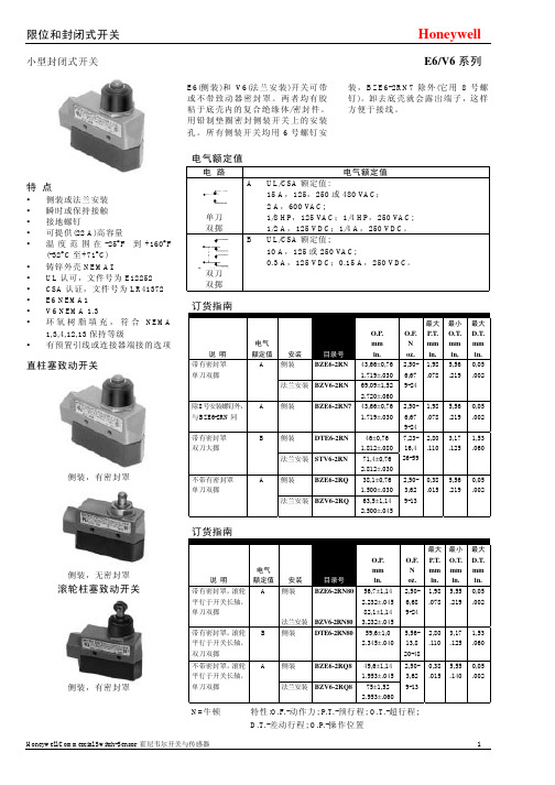
电路电气额定值单刀双掷A UL/CSA额定值:15A,125,250或480 VAC;2A,600 VAC;1/8HP,125 VAC;1/4 HP,250 VAC;1/2A,125 VDC;1/4 A,250 VDC。
双刀双掷B UL/CSA额定值;10A,125或250 VAC;0.3A,125 VDC;0.15 A,250 VDC。
小型封闭式开关E6/V6系列E6(侧装)和V6(法兰安装)开关可带或不带致动器密封罩。
两者均有胶粘于底壳内的复合绝缘体/密封件。
用铅制垫圈密封侧装开关上的安装孔。
所有侧装开关均用6号螺钉安装,BZE6-2RN7除外(它用8号螺钉)。
卸去底壳就会露出端子,这样方便于接线。
特点侧装或法兰安装瞬时或保持接触接地螺钉可提供(22 A)高容量温度范围在-25°F到+160°F(-32°C至+71°C)铸锌外壳NEMAIUL认可,文件号为E12252CSA认证,文件号为LR41372E6 NEMA1V6 NEMA 1.3环氧树脂填充,符合NEMA1,3,4,12,13保持等级有预置引线或连接器端接的选项直柱塞致动开关侧装,有密封罩侧装,无密封罩滚轮柱塞致动开关侧装,有密封罩电气额定值订货指南说明电气额定值安装目录号O.P.mmin.O.F.Noz.最大P.T.mmin.最小O.T.mmin.最大D.T.mmin.侧装BZE6-2RN 43,66±0,761.719±.030带有密封罩单刀双掷A法兰安装BZV6-2RN 69,09±1,522.720±.0602,50-6,679-241,98.0785,56.2190,05.002除8号安装螺钉外,与BZE6-2RN同A 侧装BZE6-2RN7 43,66±0,761.719±.0302,50-6,679-241,98.0785,56.2190,05.002侧装DTE6-2RN 46±0,761.812±.080带有密封罩双刀大掷B法兰安装STV6-2RN 71,4±0,762.812±.0307,23-16,426-592,80.1103,17.1251,53.060侧装BZE6-2RQ 38,1±0,761.500±.030不带有密封罩单刀双掷A法兰安装BZV6-2RQ 63,5±1,142.500±.0452,50-3,629-130,38.0155,56.2190,05.002订货指南说明电气额定值安装目录号O.P.mmin.O.F.Noz.最大P.T.mmin.最小O.T.mmin.最大D.T.mmin.侧装BZE6-2RN80带有密封罩,滚轮平行于开关长轴,单刀双掷A法兰安装BZV6-2RN8056,7±1,142.232±.04582,1±1,143.232±.0452,50-6,689-241,98.0785,55.2190,05.002带有密封罩,滚轮平行于开关长轴,双刀双掷B 侧装DTE6-2RN80 59,6±1,02.345±.0405,56-13,820-482,80.1103,17.1251,53.060侧装BZE6-2RQ8 49,6±1,141.953±.045不带密封罩,滚轮平行于开关长轴,单刀双掷A法兰安装BZV6-2RQ8 75±1,522.953±.0602,50-3,629-130,38.0155,55.1400,05.002N=牛顿特性:O.F.-动作力; P.T.-预行程; O.T.-超行程;D.T.-差动行程; O.P.-操作位置小型封闭式开关E6/V6系列交 叉滚轮柱塞执行开关法兰安装 无密封罩滚轮杠杆执行开关法兰安装 有密封罩侧装无密封罩订货指南说 明电气 额定值安 装目录号O.P.mm in. O.F. N oz.P.T. mm in.O.T. mm in.最大 D.T.mm in.侧装 BZE6-2RQ81 49,6±1,14 1.953±.045 A 法兰安装BZV6-2RQ81 75±1,52 2.953±.060 2,50- 3,62 0,38 .015 3,55 .140 0,05 .002侧装BZE6-2RN8156,7±1,14 2.232±.045 同上,有封罩 A 法兰安装 BZV6-2RN8182,1±1,14 3.232±0.452,5- 6,67 1,98 .078 5,56 .219 0,05.002无密封罩,滚轮 垂直于开关的 长轴单刀双掷9-139-24订货指南说 明电气 额定值安 装 目录号 O.F. N oz. 最大 P.T. mm in. 最小 O.T. mm in. 最大 D.T. mm in. 侧装BZE6-2RN2 单刀双掷 A 法兰安装BZV6-2RN2侧装DTE6-2RN2双刀双掷 B 法兰安装DTV6-2RN2 2,78- 8,35 10-30 6,76 .266 5,56 .219 4,19 .165 侧装 BZE6-2RQ2 单刀双掷 A 法兰安装BZV6-2RQ2 2,78- 5,01 10-184,78 .1885,56 .2190,15 .006无密封罩,同 上调节,除水 平可以45°增 量调节外双刀双掷 B 侧装DTE6-2RQ22,78- 5,57 10-206,76 .2665,56 .2194,19 .165有密封罩,现 场可作水平方 向360°调节, 垂直方向180° 调节2,78- 4,78 5 ,56 0,055,57 .188 .219 .006 10-20单向滚轮杠杆执行开关侧装 有密封罩力较小的控制杆杠杆使用时控制杆或与开关成一行或者切断。
2021年Ex-V6型号汽车指南说明书

The two levers on the steering column contain controls for driving features you use most often.The left lever controls the turn signals,headlights,and high beams.The right lever controls the windshield washers and wipers.To use the horn,press the pad around the ‘‘H’’logo.The controls under the left air vent are for the moonroof and the Traction Control System.The steering wheel adjustment lever on the underside of the steering column allows you to tilt and telescope the steering wheel.If you leave the lights on with the ignition switch in ACCESSORY (I) or LOCK (0), you will hear a reminder chime when you open the driver’s door.The rotating switch on the left lever controls the lights. Turning this switch to the ‘‘ ’’ position turns on the parking lights, taillights, and rear license plate lights. Turning the switch to the ‘‘ ’’ position turns on the headlights.To change from low beams to highbeams, push the turn signal leverforward until you hear a click.Theblue high beam indicator will light(see page).To return to lowbeams,pull the turn signal leverback.When the light switch is in either ofthese positions,the Lights Onindicator comes on as a reminder.67HeadlightsThe lights will turn on again whenyou unlock or open the driver’s door.If you unlock the door,but do notopen it within15seconds,the lightswill go off.With the driver’s dooropen,you will hear a lights-onreminder chime.To flash the high beams,pull theturn signal lever back lightly,thenrelease it.The high beams will comeon and go off.The high beams will stay on for aslong as you hold the lever back,nomatter what position the headlightswitch is in.With the headlight switch off,the high beam headlights and the high beam indicator come on with reduced brightness when you turn the ignition switch to ON(II)and release the parking brake.They remain on until you turn the ignition off,even if you set the parking brake. The headlights revert to normal operation when you turn them on with the switch.brightness when you turn the ignition switch to ON(II).If you do not insert the key in the ignition switch after opening the driver’s door,the illumination turns off in about30seconds after closing that door.If you insert the key but do not turn the ignition switch to ON(II),the illumination turns off in about10 seconds.To reduce glare at night,the instru-ment panel illumination dims when you turn the light switch to or .Turning the Select/Reset knob fully to the right until you hear a click will cancel the reduced bright-ness.Daytime Running Lights (Canadian Models)Signal a turn or lane change with this lever.Push down on the lever to signal a left turn,and up to signal a right turn.If you push it up or down all the way,the turn signal continues to blink even when you release the lever.It shuts off automatically as you complete the turn.To signal a lane change,push lightly on the turn signal lever in the proper direction and hold it.The lever will return to the center position as soon as you release it.This lever controls the windshield wipers and washers.It has five positions:MIST:mist OFF:offINT:intermittent LO:low speed HI:high speedTo select a position,push the lever up or down.CONTINUEDTurn SignalsWindshield WipersTo operate the wipers in mist mode,push the control lever up from the OFF position.The wipers run at high speed until you release the lever.This gives you a quick way to clear the windshield.In intermittent,the wipers operate every few seconds.The sweep interval will change slightly with speed;getting shorter as you drive faster.While the car is stopped and in gear,the wipers sweep the windshield whenever you remove your foot from the brake pedal.In low speed and high speed,the wipers run continuously.To clean the windshield,pull back on the wiper control lever.The washers spray until you release the lever.The wipers run at low speed while you’re pulling the lever,then complete one more sweep of the windshield after you release it.The rear window defogger will clear fog,frost,and thin ice from the window.Push the defogger button to turn it on and off.The light above/in the button lights to show the defogger is on.It also shuts off when you turn off the ignition.You have to turn it on again when you restart the car.CONTINUEDWindshield Washers Rear Window DefoggerSee page for important safetyinformation about how to properlyposition the steering wheel.18Make any steering wheel adjustmentbefore you start driving.Make sure the rear window is clearand you have good visibility beforestarting to drive.Steering Wheel AdjustmentMove the steering wheel up or down,and in or out to the desired position,making sure the wheel points toward your chest,not toward your face.Make sure you can see the instrument panel gauges and the indicator lights.Push the lever up to lock the steering wheel in that position.Make sure you have securely locked the steering wheel in place by trying to move it up,down,in,and out.To adjust the steering wheel:Insert the key in the ignition switch,and unlock the steering column.Push the lever under the steering column all the way down.3.4.5.1.2.。
开欧客滑板车说明书

CONTENTS目录CARAOK SCOOTER features 电动滑板车特征 (2)CARAOK SCOOTER Main Parts 电动滑板主要部件 (3)Warnings& general information警告和总说明 (5)Serial number序列号 (7)Opening CARAOK SCOOTER展开滑板车 (8)Folding CARAOK SCOOTER折叠滑板车 (10)Operation操作 (12)Charging battery充电与电池 (13)Power switch电源开关 (14)Throttle Speed control油门速度控制 (15)Safety安全 (15)Tires air pressure胎压 (16)Driving technique骑行技巧 (17)Maintenance of flat tire瘪胎的维修说明 (19)Maintenance 保养 (20)General Troubleshooting一般故障排除 (21)Specification and parameter产品规格与参数 (22)Scope of quality assurance品质保证范围 (23)oneCARAOK SCOOTER FEATURES 开欧客电动滑板车特点twoCARAOK SCOOTER MAIN PARTS开欧客电动滑板主要部件快速折叠装置自锁/解锁M形按扭OUICK FODING MECHANISM CARAOK WHEEL MOTOR SELF LOOKING /RELEASE M BUTTOM 电动滑板车轮毂电机ALUMINUM DECK=ANTI SKID GRIPS铝甲板+防滑手条后碟刹REAR DISC BRAKE BA TTERY CHARGER CONNECTOR电池充电器接口t h r e e维修塑料盖板MAINTENANCE PLASTIC SPEED CONTROL THROTTLEON-OFF BUTTON/BATTERY INDICATOR调速器/开-关按扭/电池指示灯LED前大灯/限速开关(左慢右快)喇叭LED HEAD LIGHT/SPEED LIMIT SWITCH (LEFTSIDE SLOW RIGHT SIDE FAST)/HORN快拆杆脚撑QUICK RELEASE KICKSTANDfourWARNINGS & GENERAL INFORMATION警告和总说明fiveCARAOK SCOOTER needs a short period for all moving parts such as hinges and brakes to adjust themselves into their correctsixposition.开始使用阶段需要一小段路程来使各个部件如铰链和刹车进入正确的位置。
Series V6 FLOTECT 流量启动器说明书
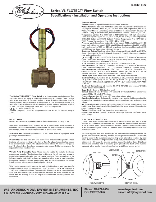
The Series V6 FLOTECT ®Flow Switch is an inexpensive, explosion-proof flow switch for use on air, water or other compatible gases and liquids. Three configu-rations are available - 1. Factory installed in a tee. 2. With a trimmable vane for field adjustment and installation in a suitable tee. 3. Low flow models with an inte-gral tee and adjustable valve. All are available with an optional enclosure which isUL and CSA listed, or Directive 2014/34/EU (ATEX) compliant forII 2 G Ex db IIC T6 GbProcess Temp≤75°C or IECEx compliant for Ex db IIC T6 Gb Process Temp ≤75°C.ELECTRICAL CONNECTIONSConnect wire leads in accordance with local electrical codes and switch action required. N.O. contacts will close and N.C. contacts will open when flow increases to the actuation point. They will return to “normal” condition when flow decreases to the deactuation point. Black = Common, Blue = Normally Open and Red =Normally Closed.For units supplied with both internal ground and external bonding terminals, the ground screw inside the housing must be used to ground the control. The external bonding screw is for supplementary bonding when allowed or required by local code. When external bonding conductor is required, conductor must be wrapped a minimum of 180° about the external bonding screw. See below. Some CSA listed models are furnished with a separate green ground wire. Such units must beequipped with a junction box, not supplied but available on special order.SPECIFICATIONSService: Gases or liquids compatible with wetted materials.Wetted Materials: Standard V6 Models: Vane: 301 SS; Lower Body: brass or 303SS; Magnet: ceramic; Other: 301, 302 SS; Tee: brass, iron, forged steel, or 304 SS.V6 Low Flow Models: Lower Body: brass or 303 SS; Tee: brass or 304 SS; Magnet:ceramic; O-ring: Buna-N standard, Fluoroelastomer optional; Other: 301, 302 SS.Temperature Limits:-4 to 220°F (-20 to 105°C) Standard, MT high temperature option 400°F (205°C) (MT not UL, CSA, ATEX, IECEx or KC) ATEX Compliant AT,IECEx IEC Option and KC (KC Option), Ambient Temperature -4 to 167°F (-20 to 75°C) Process Temperature: -4 to 220°F (-20 to 105°C).Pressure Limit: Brass lower body with no tee models 1000 psig (69 bar), 303 SS lower body with no tee models 2000 psig (138 bar). Brass tee models 250 psi (17.2bar), iron tee models 1000 psi (69 bar), forged and stainless steel tee models 2000psi (138 bar), low flow models 1450 psi (100 bar).Enclosure Rating:Weatherproof and Explosion-proof. Listed with UL and CSA for Class I, Groups A, B, C and D; Class II, Groups E, F, and G. (Group A on stainless steel body models only).0518 II 2 G Ex db IIC T6 Gb Process Temp≤75°C Alternate Temperature Class T5 Process Temp≤90°C, 115°C (T4) Process Temp ≤105°C consult factory.EC-type Certificate No.: KEMA 04ATEX2128.ATEX Standards:EN 60079-0: 2011 + A11:2013; EN 60079-1: 2014.IECEx Certified:For Ex db IIC T6 Gb Process Temp≤75°C Alternate Temperature Class T5 Process Temp≤90°C, 115°C (T4) Process Temp≤105°C consult factory.IECEx Certificate of Conformity:IECEx DEK 11.0039; IECEx Standards: IEC 60079-0: 2011; IEC 60079-1: 2014; Korean Certified (KC) for: Ex d IIC T6 Gb Process Temp≤75°C; KTL Certificate Number: 12-KB4BO-0091.Switch Type: SPDT snap switch standard, DPDT snap switch optional.Electrical Rating:UL models: 5 A @125/250 VAC. CSA, ATEX and IECEx models:5 A @ 125/250 VAC (V~); 5 A res., 3 A ind. @ 30 VDC (V ). MV option: 0.1 A @125 VAC (V~). MT option: 5 A @125/250 VAC (V~). [MT option not UL, CSA, ATEX or IECEx].Electrical Connections: UL models: 18 AWG, 18˝ (460 mm) long. ATEX/CSA /IECEx models: terminal block.Upper Body:Brass or 303 stainless steel.Conduit Connections:3/4˝ male NPT standard, 3/4˝ female NPT on junction box models. M25 x 1.5 with BSPT option.Process Connection: 1/2˝ male NPT on models without a tee.Mounting Orientation: Switch can be installed in any position but the actuation/de-actuation flow rates in the charts are based on horizontal pipe runs and are nominal values.Set Point Adjustment: Standard V6 models none. Without tee models vane is trim-mable. Low flow models are field adjustable in the range shown. See set point charts on opposite page.Weight: 2 to 6 lb (.9 to 2.7 kg) depending on construction.Options not Shown: Custom calibration, bushings, PVC tee, reinforced vane,DPDT relays.INSTALLATIONUnpack and remove any packing material found inside lower housing or tee. Switch can be installed in any position but the actuation/deactuation flow rates in the charts are based on horizontal pipe runs and are nominal values. For more pre-cise settings, units can be factory calibrated to specific flow rates.V6 Models with Tee are supplied in 1/2˝ - 2˝ NPT sizes. Install in piping with arrow pointing in direction of flow.V6 Low Flow Models have 1/2˝ NPT connections and are field adjustable. Install in piping with arrow pointing in direction of flow. To adjust, loosen the four socket head cap screws on bottom. The adjustment valve rotates 90° between “O” (open)and “C” (closed). See flow charts for approximate ranges. Tighten screws once theV6 With TeeCold Water - Factory Installed TeeApproximate actuation/deactuation low Rates3Air-Factory Installed TeeApproximate actuation/deactuation flow rates3V6 Low Flow, Field Adjustable Cold Water - Low Flow ModelsApproximate actuation/deactuation flow rates3Air - Low Flow ModelsApproximate actuation/deactuation flow rates3Example SeriesConstruction Body Switch Type Tee Connection SizeTee Type and Material OptionsV6V6EP EP1123456LF 1E 2E 3E 4E 5E 6E LFEBB S OAT182022022A 31ATBUSH2BUSH3BUSH4BUSH5BUSH6BUSH7BUSH8BUSH9BUSH10BUSH11CSA CV FTR GL ID IEC JCTLH KC MT MV NN ORFB ORFS PT RV ST TBC VITSeries V6EPB-B-D-1-B-AT Flotect ®Mini-Size Flow Switch, brass body, DPDT, 1/2"brass tee, with ATEX approval.Flotect ®Mini-Size Flow Switch Explosion Proof BrassStainless Steel DPDT SPDT 1/2" NPT 3/4" NPT 1" NPT 1-1/4" NPT 1-1/2" NPT 2" NPTLow Flow with 1/2" NPT Inlet and Outlet 1/2" BSPT ++3/4" BSPT ++1" BSPT ++1-1/4" BSPT ++1-1/2" BSPT ++2" BSPT ++Low Flow with 1/2" BSPT Inlet and Outlet ++BrassStainless SteelNO Tee with Field Trimmable Vane 0.018 Spring for Low Flow .020 Spring for Low Flow .022 Spring for Low Flow.022 Spring for Low Flow with Alnico Magnet .031 Spring for Low Flow ATEX Approval1/2" NPT x 3/4" NPT Bushing 1/2" NPT x 1" NPT Bushing 1/2" NPT x 1-1/4" NPT Bushing 1/2" NPT x 1-1/2" NPT Bushing 1/2" NPT x 2" NPT Bushing1/2" BSPT x 3/4" BSPT Bushing, M25 X 1.5 Conduit Connection ++1/2" BSPT x 1" BSPT Bushing, M25 X 1.5 Conduit Connection ++1/2" BSPT x 1-1/4" BSPT Bushing, M25 X 1.5 Conduit Connection ++1/2" BSPT x 1-1/2" BSPT Bushing, M25 X 1.5 Conduit Connection ++1/2" BSPT x 2" BSPT Bushing, M25 X 1.5 Conduit Connection ++CSA*Custom Vane Flow Test Report Ground Lead*Custom Nameplate IECEx ApprovalJunction Box with Left Side Conduit Korean Certified*High Temperature*Gold Contacts No Nameplate*Brass OrificeStainless Steel Orifice Paper TagReinforced Vane Stainless Steel TagTerminal Block Connector*Flouroelstomer SealsBB BB SSEC-Type Certificate, IECEx and KC Installation Instructions:Cable ConnectionThe cable entry device shall be certified in type of explosion protection flameproof enclosure “d”, suitable for conditions of use and correctly installed. For Ta ≥ 65°C cable and cable gland rated ≥ 90°C shall be used.Conduit ConnectionAn Ex d certified sealing device such as a conduit seal with setting compound shall be provided immediately to the entrance of the valve housing. For Ta ≥ 65°C wiring and setting compound, in the conduit seal, rated ≥ 90°C shall be used.Note:ATEX, IECEx and KC units only: The temperature class is determined by the maximum ambient and or process temperature. Units are intended to be used in ambient of -20°C≤ Tamb ≤75°C. Units may be used in process temperatures up to 105°C providing the enclosure and switch body temperature do not exceed 75°C.The standard Temperature Class is T6 Process Temp ≤75°C. Alternate Temperature Class of T5 Process Temp ≤90°C and 115°C (T4) Process Temp ≤105°C are available consult factory.Refer to Certificate No: IECEx DEK 11.0039 for conditions of safe use for IECEx compliant units.All wiring, conduit and enclosures must meet applicable codes for hazardous areas. Conduits and enclosures must be properly sealed. For outdoor or other locations where temperatures vary widely, precautions should be taken to prevent condensation inside switch or enclosure. Electrical components must be kept dry at all times.CAUTION: To prevent ignition of hazardous atmospheres, disconnect the device from the supply circuit before opening. Keep assembly tightly closed when in use.MAINTENANCEInspect and clean wetted parts at regular intervals. The cover should be in place at all times to protect, the internal components from dirt, dust and weather and to maintain hazardous location ratings. Disconnect device from the supply circuit before opening to prevent ignition of hazardous atmosphere. Repairs to be con-ducted by Dwyer Instruments, Inc. Units in need of repair should be returned to the factory prepaid.Attention:Unitswithout the “AT” suffix are not Directive 2014/34/EU (ATEX)compliant. These units are not intend-ed for use in poten-tially hazardous atmospheres in the EU. These units may be CE marked for other Directives of the EU.D D S*Options that do no have ATEX or IECEx++ BSPT options not compatible with KC optionV6 With Field Trimmable VaneCold Water - Brass or Cast Iron Reducing Tee Approximate actuation/deactuation flow rates GPM upper, M3/HR lower1.6 0.42.2 0.53.0 0.71.30.31.80.42.40.52.60.63.50.84.31.02.30.53.10.73.80.93.50.84.00.94.61.045.61.36.31.438.01.83.10.73.50.84.20.955.21.26.11.397.51.74.31.04.91.15.51.26.01.47.01.68.01.810.02.312.02.73.90.94.41.05.01.15.61.36.61.57.61.79.02.010.02.39.02.09.52.210.02.311.02.512.02.713.03.014.03.28.51.99.02.09.32.110.02.310.02.311.02.512.02.7Vane Full Size abcdefghijklm n o6.40.1810.00.2812.00.343.80.117.00.209.00.2513.00.3715.00.4220.00.5712.00.3414.00.4016.00.4516.00.4518.00.5119.00.5422.00.6225.00.7132.00.9115.00.4216.00.4517.00.4820.00.5723.00.6528.00.7920.00.5721.00.5923.00.6524.00.6828.00.7933.00.9338.01.0845.01.2718.00.5119.00.5421.00.5922.00.6225.00.7130.00.8535.00.9942.01.1925.00.7128.00.7930.00.8532.00.9134.00.9636.01.0245.01.2757.01.6139.01.1040.01.1342.01.1950.01.4255.01.5637.01.0538.01.0840.01.1344.01.2546.01.3027.00.7630.00.8532.00.9134.00.9637.01.0539.01.1051.01.4469.01.952.00.52.50.63.50.87.01.610.02.31.50.32.00.53.00.75.51.28.01.82.80.63.40.84.00.915.01.16.51.489.02.02.40.53.00.73.60.824.51.06.11.398.21.95.01.15.51.26.21.46.81.58.51.910.02.312.02.74.51.05.01.15.71.36.31.47.81.89.22.110.02.38.51.99.22.19.82.212.02.713.03.07.81.88.62.09.02.010.02.311.02.5Vane Full Size abcdefg h i j k 8.00.2311.00.3114.00.4027.00.7639.01.106.50.1810.00.2813.00.3724.00.6836.01.0212.00.3414.00.4016.00.4519.00.5426.00.7432.00.9110.00.2812.00.3414.00.4017.00.4824.00.6830.00.8518.00.5120.00.5722.00.6226.00.7430.00.8534.00.9640.01.1333.00.9339.01.1042.01.1951.01.4455.01.5630.00.8536.01.0238.01.0846.01.3050.01.4221.00.5922.00.6224.00.6828.00.7933.00.9337.01.0543.01.22Cold Water - Stainless or Forged Steel Straight Tee and Bushing Approximate actuation/deactuation flow ratesGPM upper,M3/HR lower Air - Stainless or Forged Steel Straight Tee and Bushing Approximate actuation/deactuation flow ratesSCFM upper,NM3/M lowerAir - Brass or Cast Iron Reducing Tee Approximate actuation/deactuation flow ratesSCFM upper, NM3/M lower1/2˝ NPT3/4˝ NPT1˝ NPT1-1/4˝ NPT1-1/2˝ NPT2˝ NPT6.2 1.47.0 1.6 7.6 1.78.0 1.89.0 2.0 10.0 2.3 13.0 3.0 15.0 3.45.51.26.51.57.11.67.31.78.21.99.02.011.02.513.03.01/2˝ NPT3/4˝ NPT1˝ NPT1-1/4˝ NPT1-1/2˝ NPT2˝ NPT1/2˝ NPT3/4˝ NPT1˝ NPT1-1/4˝ NPT1-1/2˝ NPT2˝ NPT1/2˝ NPT3/4˝ NPT1˝ NPT1-1/4˝ NPT1-1/2˝ NPT2˝ NPTTrimmable VaneV6 with FieldTrimmable Vane5-13/16[147.694]LOCKING COLLARASSEMBLY3/4 NPTUPPER HOUSINGSWITCH SUPPORTSSPDT (OR DPDT)SNAP SWITCHMAGNET LEVER PINMAGNET LEVERASSEMBLYMAGNETSLOWER HOUSING – BRASSOR STAINLESS STEELVANE SPRINGVANE PIVOT PINVANE PIVOTBRACKETSNAP RING1/2 NPTSTAINLESSSTEEL VANEOVERALL LENGTH WITH1-1/49 TEE CONNECTIONAPPROXIMATELY 89SPDTDPDTTerminal ConnectionsCSA, ATEX Enclosures。
进口汽车用户操作手册 Jeep Wrangler(JK)型号(2012年至2017年)V6-3.6L

advanced FLOW engineeringInstruction Manual P/N: 51-76204 / 54-76204 / 75-76204 Make: Jeep Model: Wrangler (JK) Year: 2012-2017 Engine: V6-3.6LLabel Qty. Description Part Number A1 1 Air Filter (Pro DRY S) 21-91062 (51-76204)A2 1 Air Filter (Pro 5R)24-91062 (54-76204) A3 1 Air Filter (Pro-GUARD 7) 72-91062 (75-76204) B 1 Tube 05-76204B1C 1 Housing 05-76204B2D 1 Clamp, T -bolt 03-50290E 2 Clamp, T -bolt 03-50292F 1 Coupler, Silicone, 3-1/4” ID x 2”L 05-01223G 1 Hose, Fuel 5/8” (9” Long) 05-00069H 1 Grommet, Temp Sensor 03-50167I 1 Plug, Air Box 05-00937J 1 Fitting, Air Temp Sensor 05-01336Tools needed: 8mm nut driver, 10mm nut driver, 7/16” nut driver and 1/4” driver with 10mm deep socket.Note: This intake is 50-state legal (C.A.R.B. E.O. Number D-550-14).• Please read the entire instruction manual before proceeding.• Ensure all components listed are present.• If you are missing any of the components, call customer support at 951-493-7100.• Ensure you have all necessary tools before proceeding.• Do not attempt to work on your vehicle when the engine is hot.• Disconnect the negative battery terminal before proceeding.• Retain factory parts for future use.Page 2Page 3A3A2DB A1C E EF H IJGFigure ARefer to Figure A for Step 1Step 1: Remove the engine cover by lifting firmly out of the vehicle.Page 42Refer to Figure B for Steps 2-6Step 2: Remove the two 10mm bolts from the intake tube. 1Step 3: Disconnect the temp sensor wire harness. 2Step 4: Loosen the hose clamp at the throttle body.Step 5: Completely remove the small section of crankcase vent (CCV) hose. It should be pulled off of the air filter housing and the tube to the engine. 3Step 6: Remove the stock intake tube, and air filter housing by pulling straight up and out of the vehicle.Page 5Step 7: Twist the temp sensor about 45 degrees counter-clockwise and pull it straight up to removefrom stock tube.Page 64Figure DRefer to Figure D for Step 8Step 8: Remove the 10mm bolt that secures the plastic tray onto the inner fender, but do not remove the plastic tray. 4 This screw will be reused in later step.Page 75Refer to Figure E for Step 9Step 9: Install the housing into the vehicle as shown 5 . Secure the hosuing using the stock screw removed in Step 8.Page 8Step 10: Slide 7.00” clamp over flange on housing 6 .Step 11: Install the air filter into the housing and slide clamp 5.50” over end of filter 7 .Page 9Refer to Figure F for Steps 10-1176Figure GRefer to Figure G for Steps 12-13Step 12: Insert the billet adaptor into the grommet.Step 13: Insert the factory temp sensor into the billet adaptor and twist 1/8 turn until the plastic tab locks over the small bump on the adaptor.Page 10Figure HRefer to Figure H for Step 14 Step 14: Plug in the temp sensor harness.Refer to Figure I for Steps 15-19Step 15: Place the silicone coupler onto the small end of the intake tube 8 .Step 16: Place the two 3.50” clamps over the coupler and then drop tube assembly into the filter 9 .Step 17: Place the larger end of the intake tube into the filter first then slide onto throttle body. Make sure all of the t-bolt clamps are loose at this time in order to install the tube easily.Step 18: Snap the coolant overflow line into the clip on the front of the aFe intake tube.Step 19: Install the new CCV hose (Note: use lubricant on the outside of the aFe tube).Figure I895Figure JRefer to Figure J for Step 20Step 20: Tighten all clamps and re-install engine cover. Your install is now complete.*Verify all connections are secure 100-200 miles after installationTo purchase any of the items above, view airflow charts, dyno graphs, photos, and video; please go to .Pro DRY S Air FilterP/N: 21-91062P/N: 24-91062P/N: 90-50501P/N: 90-59999Pro 5R Air FilterPro DRY S Restore KitBlue Squeeze Restore KitP/N: 90-50500Gold Squeeze Restore Kit P/N: 72-91062Pro-GUARD 7 Air Filter P/N: 46-70162 (Dana 44) 46-70192 (Dana 30)Differential CoverP/N: 49-48056-B (Black Tips) 49-48056-P (Polished)Exhaust SystemP/N: 77-16203 (M/T) 77-16204 (A/T)Sprint BoosterP/N: 46-79001Glide GuardP/N: 46-35003Throttel Body SpacerP/N: 49-08045-PExhaust SystemWarrantyGeneral Terms:• aFe warrants their products to be free from manufacturer’s defects due to workmanship and material.• This warranty applies only to the original purchaser of the product and is nontransferable.• Proof of purchase of the aFe product is required for all warranty claims.• Warranty is valid provided aFe instructions for installation and/or cleaning were properly followed.• Proper maintenance with regular inspections of product is required to insure warranty coverage.• Damage due to improper installation, abuse, unauthorized repair or alteration is not warranted.• Incidental or consequential damages or cost, including installation and removal of part, incurred due to failure of aFe product is not covered under this warranty.• All warranty is limited to the repair and/or replacement of the aFe part. To request Return Goods Authorization (“RGA”),***************************(951)493-7100.UponreceiptoftheRGA,youmustreturntheproduct to the address provided in the RGA, freight prepaid and accompanied with a dated proof of purchase and the RGA.Upon receipt of the defective product and upon verification of proof of purchase, aFe will either repair or replace the defective product within a reasonable time, not to exceed thirty days.Product Category P/N Prefix Warranty duration Direct OE Replacement Filters 10, 11, 30, 31, 71, 73 Life of the vehicle Racing Filters 18 1 year Universal 21, 24, 72 2 yearsAir Intake Systems 50, 51, 54, 55, 75 2 yearsExhaust Systems 49 2 years Intercoolers & Intercooler Tubes 46-2 2 yearsIntake Manifolds 46-1 2 years Differential Cover 46-7 Life of the vehicle Exhaust Manifolds 46 2 yearsThrottle Body Spacers 46-3 2 yearsFluid Filters 44 90 daysPre-Filters 28 2 yearsHeavy Duty OE Replacement 70 2 years PowerSports OE Replacement 81, 87 2 years PowerSports Intake Systems 85 2 yearsNo other warranty expressed or implied applies nor is any person or advanced FLOW engineering authorized to assume any other warranty. Some States do not allow the exclusion or limitation of incidental or consequential damages or do not allow limitations on how long an implied warranty lasts, so the above limitations or exclusions may not apply to you. This warranty gives you specific legal rights, and you may also have other rights which vary from State to State.advanced FLOW engineering, inc.252 Granite Street Corona, CA 92879TEL: 951.493.7155 • TECH: 951.493.7100。
Vectron Commander v6用户手册说明书
PC Software Vectron Commander v6 user ManualMANUALVECTRON COMMANDERPAGE 1/1Release Dec202000Dear Customer,Your purchase of VECTRON COMMANDER6gives you a powerful program to maintain yourVectron POS system and provide the information you need to run your business.With VECTRON COMMANDER6you may connect up to1,000POS Terminals and have fullcontrol over essential programming such as PLUs and Prices from your Head Office.Sales Datacan be polled automatically,or on-demand so you can stay on top of any hot spots.This polleddata can be formulated to provide the reports you need.The terminals can be polled on-line or bymodem or ISDN.Administer all your worldwide terminals from your Headquarters.I BasicsI.I Structure of this manualI.I.I StructureThis Manual has3parts.Part1covers installation,connecting COMMANDER with the terminals, and the basic concepts of operating the software.Part2explains each Function in detail.Part3 are supplements with additional information for external Help programs and connection of terminals.I.I.2.Conventions‘README.TXT’a Folder or Filename.‘SETTINGS’a Menu item‘<INSERT>’a keyor a button1.2Latest informationThe information contained in this manual is the latest that was available at the time ofprinting.As Commander is constantlybeing improved,the latest information will be in the ‘VC_READM.HTM’or‘VC_READM.TXT’and‘VCCHANGE.TXT’files,which areautomaticallyinstalled with VECTRON COMMANDER6.1.3.Backing up your dataCOMMANDER6is saving your very important data on your hard drive.A failure of thisdrive could cause immense economic damage.Therefore you should save your datafrom time to time.Some of the options are floppydisks,CD-ROM or tapes.Your PCvendor can suggest the method that is best for you.All the files in theVECTRON\VCOM6\DATA folder should be backed up regularly.2Installation of COMMANDER6If your dealer has installed COMMANDER6for you,please continue with CHAPTER3.2.1Installation of Hardlock(Dongle)Before you will install COMMANDER6,you should install the Hardlock(Dongle),which is included with your software.Remove the printer cable from the parallel port of yourcomputer.With the end marked‘parallel’facing the computer,screw the Hardlock to the parallel port.Connect the printer cable with the free end of the Hardlock.Install the Hardlock driver.You will find this driver on the CD-ROM in the\DRIVERSfolder.If a printer is connected to the Hardlock,it should be switched ON when startingCommander.2.2Installation of VECTRON COMMANDER6• Insert the CD in your CD ROM Drive• Double click on MY COMPUTER and then click the CD ROM drive • Change to folder\PROD\VCOM6• Double click the file VCOM6-6XXX-YYY.EXE.• Where X XX=the current release and YYY=the language desiredThe installation program will start.If VECTRON COMMANDER6is alreadyinstalled,y ou will see a window labeled‘Vectron Commander6Maintenance’.In this case pleasecontinue with Chapter2.2.2.2.2.1New installationIf this is a new installation you will see a number of windows:WELCOMEClick<NEXT>to continueINFORMATIONPlease take a moment to read the information on this page as there will be importantrelease and installation notes that are not yet in the manualDESTINATION LOCATIONHere you will define the Folder for installation.C:\VECTRON\VCOM6should be changed onlyin exceptional cases.This is a “Table of Contents preview” for quality assuranceThe full manual can be found at /estore/catalog/ We also offer free downloads, a free keyboard layout designer, cable diagrams, free help andsupport. : the biggest supplier of cash register and scale manuals on the net。
2022年 Lexus 轿车系列 Sunroof 操作说明书

Sunroof (LS/GS) To open or close the sunroof, push and hold the switch. Release the switch when the sunroof reaches the desired position.Do not hold the switch on after the sunroof has fully opened orclosed, or you may damage the sunroof motor.Do not allow any part of your body to extend through the sunroof while the vehicle is in motion. In the event of a collision or sudden application of the brakes, severe personal injury couldresult.To avoid the possibility of injury while closing the sunroof, never allow any part of your body to extend through the opening.CAUTION:Operating the sunroof in severe cold or when it is covered with snow or ice may cause damage to the sunroof.SunshadeAs well as the sunroof, there is a sliding sunshade which you can adjust to let in light with the roof closed, or to block out light entirely. The sunshade automatically opens as you open the sunroof.(cont'd) CloseOpenPOP-UP WINDDEFLECTORSUNSHADESunroof (cont'd)If the Sunroof Won't CloseThe sunroof can be closed manually,if the control switch will not close it.1. Remove the round plug near the rear center of the headliner.2. Insert the sunroof wrench (from the tool kit) into the socket.3. Turn the wrench until the sunroof seats in the closed position.4. Replace the plug.Remove plugMaintenancePeriodically pour a little water down the drain holes to make sure they are not plugged. If they are free, water should drop on the ground behind each front wheel.CAUTION:Do not put weight on the sunroof or force it open or closed, you may damage the mechanism.SOCKETDRAIN HOLEStereo Sound System (LS/GS)(LS)(GS)ON/OFF Switch On the LS model:Turn the switch clockwise to turn the unit on; turn it counterclock-wise to turn the unit off.On the GS model:Push the button to turn the unit on; push it again to turn the unit off.NOTE:The antenna will rise or retract automatically when the unit is turned on or off. It will also retract automatically if the ignition isswitched off.Volume Control On the LS model:Turn the ON/OFF switch clockwise to increase volume and counter-clockwise to decrease volume.On the GS model:Push the switch up to increase volume and down to decrease volume.(cont'd)Bass ControlTreble ControlBass ControlTrebleControlStereo Sound System (cont'd)Balance ControlBalances sound between left and right speakers.NOTE:When the headlights are on, the radio panel illumination is on, even if the radio is turned off.The panel lighting can be turned off by first pushing the Balance Control button to its out position and then pulling it out slightlyfurther.Fader ControlBalances sound between front and rear speakers.AM/FM Band SelectorPush to select AM or FM band. The corresponding band indicatorwill light.Manual TuningPush the button to tune to a lower frequency station.Push the button to tune to a higher frequency station.NOTE:If you hold either button for more than half a second, the tuning frequency will count up or down rapidly.Radio Operation Frequency Display (LS)(GS)FrequencyDisplaySeek TuningEach time you push this button up or down, the tuner will automatically seek the next higher or lower frequency station.Preset Station Selection1. Make sure the Band Selector is on the band you want ... AM orFM. Then, find the station you want by Manual Tuning or Seek Tuning.2. Press and hold one of the Preset Buttons.3. In a few seconds, a beep will sound and the light in the button will come on. The station is now preset in the memory. You may preset 1 AM and 1 FM station per button, (total, 6 of each on the4. LS model and 8 of each on the GS model).You can tune to a preset station by pushing its corresponding preset button.NOTE:(On the GS model)The Auto Select Button must be off before the Preset Station Selection can be used.Auto Select Button (GS only)If you are visiting a new broadcast area, you can quickly enter into memory the stronger stations in that area by simply pushing the Auto Select Button. The radio will then automatically scan both the AM and FM bands and temporarily memorize up to eight stations in each. With the Auto Select Button on, these stations can then be tuned by pushing the preset buttons. Manually-preset stations remain memorized for use when you return to your normal broadcast area, but are only selectable with the Auto Select Button off.Stereo IndicatorThis lights up when a FM broadcast in stereo is being received. It will flash when the signal strength diminishes. If it flashes, good stereo reception cannot be expected. Stereo reception is available only for FM stereo broadcasts, not for AM stereo broadcasts.(cont'd)Stereo Sound System (cont'd)Tape Operation(GS)Tape Direction IndicatorWith the cassette inserted "A " side up, the indicator ( ) will light when the "A " side is playing; the indicator ( ) will light when the "B" side is playing.Program Selector (PROG)Push to change the direction of tape play.Auto Reverse Feature: The tape direction automatically reverses when the end of the tape is reached in play or FF mode and plays the other side.(LS)Fast Forward/Rewind (FF/REW)Note which Tape Direction Indicator is lighted, then push the appropriate button to rapidly wind the tape in the same direction (FF) or in the opposite direction (REW).Play (PLAY)Push the PLAY button (indicator on) to resume tape play and stop rewind or fast forward operation.Repeat Button (REPEAT)Push the REPEAT button (indicator on) to return to the beginning of a song or section of programming and repeat its play. Push the button again (indicator off) to cancel the repeat function and resume normal play.Dolby ® Noise Reductio n ( )Push when playing tapes recorded in Dolby NR (the Dolby NR indicator will light). Push again when playing tapes not recorded in Dolby NR. Use of the wrong setting will affect high frequency response.NOTE:The Dolby NR circuit will not operate during radio reception.Dolby noise reduction system is manufactured under license fromDolby Laboratories Licensing Corporation. "Dolby" and the double-D symbol are trademarks of Dolby Laboratories Licensing Corporation.Skip ButtonThe circuit senses silent passages between songs or programs on a tape. Push upward to automatically advance to the beginning of the next song, or downward to return to the beginning of the song just played.NOTE:Tapes that contain short silent passages between songs, a high level of noise between songs, or silent passages within a song may not be suitable for this function.Metal Indicator (METAL)Most metal or CrO 2 cassettes are coded with slots on their back edge. If such a cassette is inserted, the player will detect the slots and automatically switch to the proper equalization for full enjoyment of metal/CrO 2 tapes. The indicator light will go on when coded cassettes are played.(cont'd)Stereo Sound System (cont'd)Eject (EJECT)Push this button to stop and eject the tape.Ignition Key-OFF Eject: The cassette being played will be automat-ically ejected when the ignition or the unit is turned off.NOTE:When one side of the tape ends, "Auto-Reverse" will automatically begin playing the other side, therefore, you must push the eject button to stop or remove the tape.CLEAN Indicator LightAfter 50 hours of cassette tape play, the light will come on as a reminder to clean the tape heads. If the light comes on and the tape heads were not cleaned at the recommended 30 hours of usage (see maintenance section below), they should be cleaned immediately. To reset, push the indicator for a minimum of five seconds until the light goes off.MaintenanceThe head in the cassette tape player can pick up dirt or tape deposits each time a cassette is played. The result is low or "muddy" sound from one or both channels, as if the treble tone control were turned all the way down. To prevent this, you should periodically clean the head with a commercially available cleaning cassette.As preventive maintenance, clean the head about every 30 hours of use. If you wait until the head becomes very dirty (noticeably poor sound), it may not be possible to remove all deposits with a simple cleaning cassette.The use of 120 minutes tapes is not recommended.CAUTION:Storing cassettes out of their cases, or touching the magnetic tape with your fingers will increase the amount of dirt that gets to the tape head. Using low-quality "off-brand" tape will increase the amount of tape deposits that get on the head. Both of these practices may eventually lead to damage of the head and playing mechanism.Gasoline For proper operation of your car's emission controls, your engine is designed to use unleaded fuel only.CAUTION:Using leaded or even low-lead gasoline could damage some of your emission controls, and also void their coverage under the emission controls warranty.Use gasoline from pumps labeled unleaded, with a pump octane number of 86 or higher. The pump octane number is an average of the Research (R) octane and Motor (M) octane numbers. Use of a lower octane gasoline can cause persistent, heavy "spark knock" (a metallic rapping noise), which can lead to engine damage if severe.CAUTION:If you notice steady spark knock while holding a steady speed on a level road, try changing brands of gasoline. If the spark knock persists, consult your Acura dealer. Failure to do so is considered misuse, and misuse is not covered under the New Car Warranty.Occasionally you may notice light spark knock while accelerating or driving up hills. This is no cause for concern, it simply means your engine is running at its most economical.Gasoline Containing AlcoholIf you decide to use a gasoline containing alcohol ("gasohol"), be sure its octane rating is at least as high as that recommended for unleaded gasoline. There are two types of "gasohol": that containing ethanol, and that containing methanol. Do not use gasohol that contains more than 10% ethanol. Do not use gasoline containing methanol (methyl or wood alcohol) that does not also contain cosolvents and corrosion inhibitors for methanol. Never use gasoline containing more than 5% methanol, even if it has cosolvents and corrosion inhibitors.(cont'd)Gasoline (cont'd)NOTE:Fuel system damage or vehicle performance problems resultingfrom the use of such fuels is not covered under the new car warranties. The Acura Automobile Division cannot endorse the use of fuels containing methanol since evidence of their suitability is as yet incomplete.Before purchasing fuel from an unfamiliar station, try to confirmwhether the fuel contains alcohol, of what kind, and how much. If you notice any undesirable operating symptoms after using a gasoline that contains alcohol; or one that you think contains alcohol, switch to an unleaded gasoline as recommended on page55.Operation In Foreign CountriesIn order to comply with U.S. Federal Emission Regulations, you must use unleaded fuels of the recommended octane rating. These fuels may not be available in other countries. If you intend taking your car outside the U.S. or Canada, write to the Acura Automobile Division (stating the year and model of your car) at the address below for information regarding modifications you may need to have done.Acura Automobile DivisionCustomer Relations Office.1919 Torrance Blvd.Torrance, CA 90501-2746。
- 1、下载文档前请自行甄别文档内容的完整性,平台不提供额外的编辑、内容补充、找答案等附加服务。
- 2、"仅部分预览"的文档,不可在线预览部分如存在完整性等问题,可反馈申请退款(可完整预览的文档不适用该条件!)。
- 3、如文档侵犯您的权益,请联系客服反馈,我们会尽快为您处理(人工客服工作时间:9:00-18:30)。
个人3D私密移动影院
CARAOK V6使用说明
一.前言
感谢您选择我们的高科技电子产品.使用本产品前请认真阅读说明书. 如果您开始使用本产品,我们将认为您已经仔细阅读过本手册. 本公司对于本文档的内容不提供任何明示或隐含的陈述或担保,特别是对于适销性和针对特定目的的适用性不提供任何担保。
另外,本公司保留修订本出版物和随时修改本文档内容而不需要通知任何人的权利。
二. 产品特征
1.3D私密移动影院.
2.80寸(3M)高清640x360高画质显示效果
3.惊艳3D操作界面
4.350°近视可裸眼观看
5.3D引擎驱动、2D/3D视频播放
6.瞳距电子调节
7.1080P全格式视频/音乐播放
B Host U盘/TF卡扩展到32G
9.人体工学设计佩戴舒适
10.内置电池可视频播放4小时
11.A/V输入
12.立体声耳机输出
三. 显示和按键功能说明
(请注意充电请使用DC电源口(如上图标示),勿错使用USB插口,否则会充不进电。
)
四.重要注意事项
观看视频图像有些人可能会出现不适的症状(如眼镜疲劳、眩晕),建议定期休息,休息的时间和频率因人而异。
✧不要把产品直接裸放在太阳下,或阳光下的汽车内和海滩上.
✧不要直接把产品放在太冷,太热,灰尘太多和潮湿的环境中.
✧不要去碰撞,或其它坚硬的东西, 产品将会被损坏.
✧把TF卡插入或拔出这期间,请关掉电源. 否则可能会损坏TF卡或机器软件。
✧儿童观看,需经成人合适地指导。
✧不要去打开产品的外壳.
✧不要把产品放在太干燥的地方,避免被静电损坏.
✧在不使用机器时请长按电源键进行关机。
✧内置电池如果长期不使用本产品,每六个月给电池充一次电,以防止电池劣化。
专业温馨提示:
✧左右近视度数相差过大而裸眼观看的使用者,或者瞳距过宽或过窄的使用者,
观看效果可能欠佳或引起不适,不建议使用。
✧如镜片脏,请用干净的眼镜布轻拭干净。
✧默认设定下,在连续观看2小时之后将提示自动关机讯息,如果您清除该讯息
并继续观看,系统会在另外2小时后自动关机。
✧电量过低时系统会提示,如要继续长时间观看请切换外接电源。
✧近视眼观看;0~350度近视可裸眼观看,超过范围可佩戴眼镜或隐形眼镜观看,
请注意,使用双焦眼镜观看效果可能不太理想。
五.操作方法介绍:
1.开机:长按电源即可开机,开机后长按电源键即可关机。
2.主菜单;长按键进入主菜单
2.视频和音乐播放
在主菜单选择视频或音乐模式,键进入或选择,再按▲键和▼键去选择您需要播放的视频。
在播放视频或音乐的过程中短按键可暂停/播放视频或音乐文件,长按方向键
的按▲键或▼键可快进或快退,按方向键的左键或右键为音量调节,按键退出播放窗口。
4.AV输入模式;正确连接好外部输入设备的音视频线,确认外部视频有输出后选择AV输入按OK键可看视频
4.语言
可选择中文英文两种模式
5.断电记忆;按ok键可选择断电记忆打开和关闭,如打开则开机后即可在断点播放。
6.瞳距调节;根据不同人的瞳距大小,有3种模式选择,可选择最清晰的模式返回即可。
7.关闭电源
自动关机设置,可以选择“从不”、“30分”、“1小时”、“2小时”后自动关机。
七.电池充电
将本产品通过USB电源线可直接对本产品进行充电。
用正规厂商的电源适配器输出DC5V/1A(另购)充电(请注意充电请使用DC电源口,勿错使用USB插口,否则会充不进电。
)
将电源适配器插到AC220V插座上, 然后用USB电源线产品USB端子进行充电
当充电时大约4~5小时可将空电池充满.
*新电池充电必须充到12小时结束,开始使用前3次最好充电12小时.
八.穿戴调节
佩戴可根据使用者舒适度或角度从以下三处灵活调节长度。
九.HOST外接U盘操作;如图可通过读卡器或U盘链接读取音视频文件
本产品以实物为准。
保证卡。
