郑州托莱斯气象百叶箱型温湿度传感器技术说明书
湿度与温度传感器产品说明书
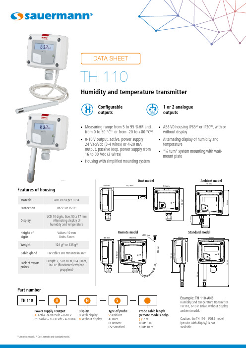
• Measuring range from 5 to 95 %HR and from 0 to 50 °C (1) or from -20 to +80 °C (2)• 0-10 V output, active, power supply24 Vac/Vdc (3-4 wires) or 4-20 mAoutput, passive loop, power supply from 16 to 30 Vdc (2 wires)• Housing with simplified mounting system• ABS V0 housing IP65(2) or IP20(1), with orwithout display • Alternating display of humidity and temperature • “¼ turn” system mounting with wall-mount plateFeatures of housingPart numberPower supply / Output A : Active 24 Vac/Vdc – 0-10 V P : Passive – 16/30 Vdc - 4-20 mA Display O : With display N : Without displayType of probe S : Ambient A : Duct D : Remote ES : StandardExample: TH 110-ANSHumidity and temperature transmitter TH 110, 0-10 V active, without display, ambient model.Caution: the TH 110 – POES model (passive with display) is not availableConfigurable outputs1 or2 analogue outputs(1)Ambient model / (2) Duct, remote and standard model.Ambient modelDuct modelProbe cable length (remote models only)( ): 2 m 05M: 5 m 10M: 10 mStandard modelTechnical specificationsConnectionsInside the front housing 1. Active switch (S1)2. Inactive switch3. LCC-S software connection4. Output terminal block5. Power supply terminal block6.Cable glandSimplified calibrationElectronic board and measuring element connected to the front side of the sensor, which allows toconfigure and calibrate your device without causing any damage.12Removable front face Fixed back housingGeneral features*Can be configured by switch.**All the accuracy indicated in this technical datasheet were stated in laboratory conditions, and can be guaranteed for measurements carried out in the same conditions, or carried out with calibration compensation.Measuring range Analogue output*654316354(standard model)Electrical connections as per NFC15-100 standardsThis connection must be made by a qualified and trained technician.IRH Vdc IT Vdc 1 2 hilos - +- +IRH Vdc IT Vdc IRH VdcIT Vdc IRH VdcIT Vdc symbol:F T _E N – T H 110 – 06/01/23 – N o n -c o n t r a c t u a ld o c u me n t – W e r e s e r v e t h e r i g h t t o m o d if y t h e c h a r a c t e r i s t i c s o f o u r p r o d u c t s w i t h o u t p r i o r n o t i c e .Only the accessories supplied with the device must be used.T o configure the transmitter , it must not be energized. Then, you can make the settings required, with the DIP switches (as shown on the drawing below).When the transmitter is configured, you can power it up.Please follow carefully the combinations beside with the DIP switch. If the combination is wrongly done, the following message will appear on the display of the transmitter “CONF ERROR”. In that case, you will have to unplug the transmitter , place the DIP switches correctly, and then power the transmitter up.1234Off OnActive switchUnit settingOutput setting On-off switch1234Active switch (S1)Please refer to the user manual of the LCC-S software to make the configuration.Set the DIP switches as shown beside. Connect the cable of the LCC-S to the connection of the transmitter .PC configurationSettings and use of the transmitterIt is possible to set the measuring ranges and the unit of the instrument either by switch and/or via software.Configurationis correctly installed. Ambient model does not have any mounting plate. 4 fixing holes are present inside the back Configuration via LCC-S software (option)It is possible to configure intermediate ranges, an offset...Example: for a 0-100 °C transmitter, minimum delta is 20 °C.The instrument can be configured from 0 to +20 °C or from -10 to +10 °C. In order to compensate a possible drift of the sensor, it is possible to add an offset to the displayed value by the TH 110 transmitter: it shows 48% RH, a standard instrument shows 45% RH. It is then possible, via the software, to integrate an offset of -3 to the displayed value by the TH 110 instrument.The configuration of the parameters can be done either with the DIP switch or via software (you can not combine both solutions).WarrantyInstruments have 1-year guarantee for any manufacturing defect.Maintenance:• Avoid any aggressive solvent.• Protect the transmitter and its probes from any cleaning product containing formalin, that may be used for cleaning rooms or ducts.Precautions for use: always use the device in accordancewith its intended use and within parameters described in the technical features in order not to compromise the protection ensured by the device.。
温湿度传感器(型号:WHT20B)使用说明书

温湿度传感器(型号:WHT20B)使用说明书版本号:1.0实施日期:2023-02-01郑州炜盛电子科技有限公司Zhengzhou Winsen Electronic Technology Co.,Ltd声明本说明书版权属郑州炜盛电子科技有限公司(以下称本公司)所有,未经书面许可,本说明书任何部分不得复制、翻译、存储于数据库或检索系统内,也不可以电子、翻拍、录音等任何手段进行传播。
感谢您使用本公司的系列产品。
为使您更好地使用本公司产品,减少因使用不当造成的产品故障,使用前请务必仔细阅读本说明书并按照所建议的使用方法进行使用。
如果您没有依照本说明书使用或擅自去除、拆解、更换传感器内部组件,本公司不承担由此造成的任何损失。
您所购买产品的颜色、款式及尺寸以实物为准。
本公司秉承科技进步的理念,不断致力于产品改进和技术创新。
因此,本公司保留任何产品改进而不预先通知的权力。
使用本说明书时,请确认其属于有效版本。
同时,本公司鼓励使用者根据其使用情况,探讨本产品更优化的使用方法。
请妥善保管本说明书,以便在您日后需要时能及时查阅并获得帮助。
郑州炜盛电子科技有限公司WHT20B温湿度传感器产品描述WHT20B温湿度传感器嵌入了适于回流焊的双列扁平无引脚SMD封装,温度和湿度信号可以在不同的引脚读出,底面3.0×3.0mm,高度1.0mm。
传感器输出经过标定的数字信号,标准I2C格式。
WHT20B温湿度传感器,包含一个全新设计的ASIC专用芯片内置晶体管Vbe温度特性,实现高精度温度检测;同时包含一个电容湿度芯片,其中湿敏材料吸湿后介电常数变化实现环境湿度检测。
并结合最新的集成电路信号处理技术而成的双芯片解决方案。
具有体积小、功耗低、可靠性高、兼容性好等优点。
产品特点⏹高精度,±3.0%RH和±0.5℃⏹宽电源电压范围,从2.0V到5.5V⏹采用SMD封装,适于回流焊⏹响应迅速、抗干扰能力强⏹高湿条件下优异的长期稳定性应用场景家电领域:家电、湿度调节、暖通空调、除湿机、智能恒温器、房间监视器;工业领域:汽车、测试及检测设备、自动控制;其他领域:数据记录器、气象站、医疗及其他相关温湿度检测控制。
温湿度传感器产品说明书
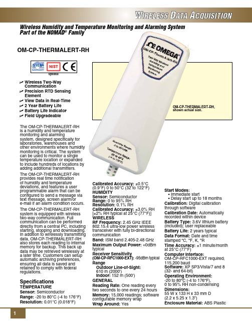
Dimensions: 55 W x 133 H x 33 mm D (2.2 x 5.25 x 1.3")
Enclosure Material: ABS Plastic
To Order
Model No.
Description
OM-CP-THERMALERT-RH
Wireless humidity and temperature transmitter
OM-CP-THERMALERT-RH-CERT Wireless humidity and temperature transmitter with NIST calibration certificate
Ordering Example: OM-CP-THERMALERT-RH-CERT, wireless humidity and temperature transmitter with NIST calibration certificate and OM-CP-RFC1000-EXT, wireless transceiver package.
OM-CP-RFC1000-IP69K Splash proof (IP69K) wireless transceiver package includes RF transceiver, USB cable, Windows software and operator’s manual (not CE approved)
Specifications
Temperature
Sensor: Semiconductor
郑州托莱斯风速风向仪技术说明书
输 入
5V、12V、24V 可选
5V、12V、24V 可选
输 出
1、脉冲信号;
2、电流:4-20mA;
3、电压:0-2.5VDC、0-5VDC;
4、RS232/RS485网络通讯;
5、TTL电平:频率和脉宽两种
1、脉冲信号;
2、电流:4-20mA;
3、电压:0-5VDC;
4、RS232/RS485网络通讯;
风速风向仪技术说明书
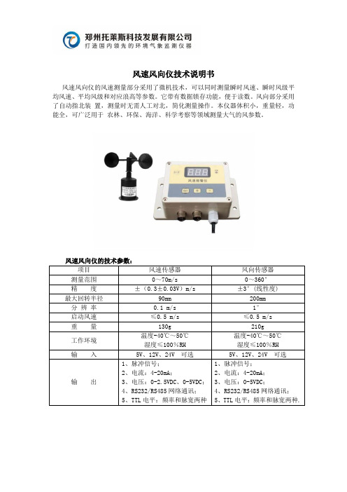
风速风向仪的风速测量部分采用了微机技术,可以同时测量瞬时风速、瞬时风级平均风速、平均风级和对应浪高等参数。它带有数据锁存功能,便于读数。风向部分采用了自动指北装 置,测量时无需人工对北,简化测量操作。本仪器体积小,重量轻,功能全,可广泛用于 农林、环保、海洋、科学考察等领域测量大气的风参数。
风速风向仪的技术参数:
项目
风速传感器
风向传感器
测量范围
0~70m/s
0~360°
精 度
±(0.3±0.03V)m/s
±3°(线性度)
最大回转半径
90mm
200mm
分 辨 率
0.1 m/s
1°
启动风速
≤0.5 m/s
≤0.5 m/s重Fra bibliotek量130g
210g
工作环境
温度-40℃~50℃
湿度≤100%RH
温度-40℃~50℃
5、TTL电平:频率和脉宽两种.
托莱斯森林气象站技术说明书
森林火险气象监测站技术说明书
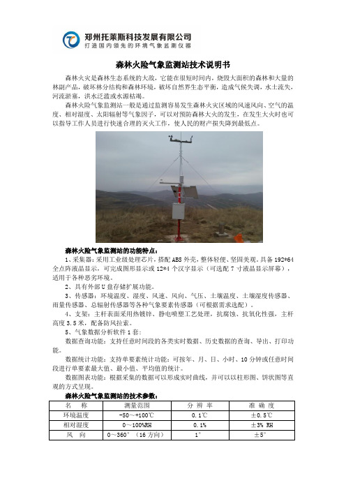
森林火灾是森林生态系统的大敌,它能在很短时间内,烧毁大面积的森林和大量的林副产品,破坏林分结构和森林环境,破坏自然界生态平衡,造成气候失调,水土流失,河流淤塞,洪水泛滥或水源枯竭。
森林火险气象监测站一般是通过监测容易发生森林火灾区域的风速风向、空气的温度、相对湿度、太阳辐射等气象因子,可以对预防森林大火的发生,在发生大火时也可以指导工作人员进行快速合理的灭火工作,使人民的财产损失降到最低点。
森林火险气象监测站的功能特点:
1、采集器:采用工业级处理芯片,搭配ABS外壳,整体轻便、坚固美观。
具备192*64全点阵液晶显示,可完成图形显示或12*4个汉字显示(可选配7寸液晶显示屏幕),适用于各种恶劣环境。
2、具有外部U盘存储扩展功能。
3、传感器:环境温度、湿度、风速、风向、气压、土壤温度、土壤湿度传感器、雨量传感器、总辐射传感器等各种气象要素传感器(可根据需求选配)。
4、支架:主杆表面采用热镀锌、静电喷塑工艺处理,抗腐蚀、抗氧化性强,主杆高度3.5米,配备防风拉索。
5、气象数据分析软件1套:
数据查询功能:支持任意时间段的各类实时数据、历史数据的查询、导出、打印功能。
数据统计功能:支持单要素统计功能:可按年、月、日、小时、10分钟或任意时间段进行单要素最大值、最小值、平均值的统计。
数据图表功能:根据采集的数据可以形成实时曲线,并可以以柱形图、饼状图等直观的方式呈现。
温湿度传感器产品说明书 ZZ-THS-ST
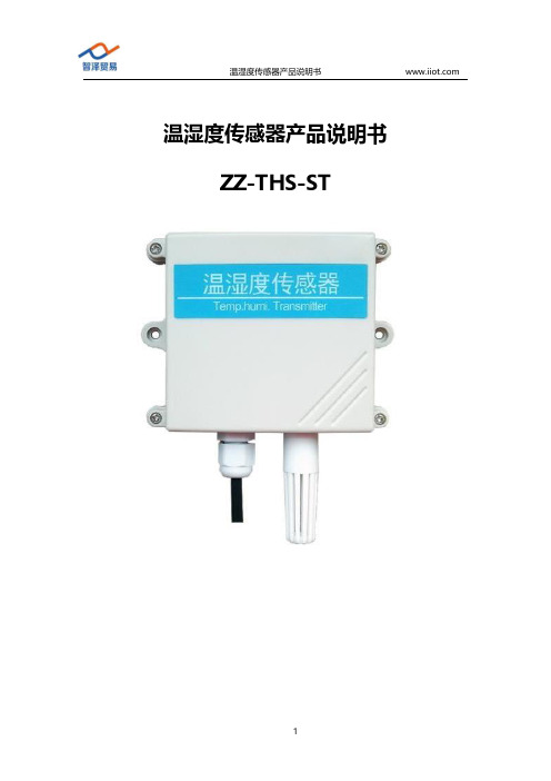
温湿度传感器产品说明书ZZ-THS-ST目录温湿度传感器产品说明书 (1)ZZ-THS-ST (1)1.产品简介 (3)1.1产品概述 (3)1.2功能特点 (3)2.参数详情 (4)2.1外形尺寸图 (4)2.2基本参数 (4)2.3模拟量参数含义 (5)2.3.1模拟量4-20mA电流输出 (5)2.3.2模拟量0-10V电压输出 (5)2.3.3模拟量0-5V电压输出 (6)2.4通讯协议 (6)2.4.1通讯基本参数 (6)2.4.2数据帧格式定义 (7)2.4.3寄存器地址 (9)2.4.4通讯协议示例以及解释 (9)3.安装使用 (11)3.1系统架构图 (12)3.1.1直接接电脑或者PLC (12)3.1.2网络传输使用 (13)3.2接口说明 (13)3.3接线说明 (14)3.3.1典型四线制接线方式 (14)3.3.2典型三线制接线方式 (16)3.4协议调试(只适用于485输出型) (17)4.包装售后 (21)4.1产品包装清单 (21)4.2联系方式 (21)4.3质保与售后 (21)4.4免责声明 (22)1.产品简介1.1产品概述该变送器广泛适用于农业大棚/花卉培养等需要温湿度监测的场合。
传感器内输入电源,感应探头,信号输出三部分完全隔离。
安全可靠,外观美观,安装方便。
1.2功能特点●探头灵敏度高●信号稳定,精度高●测量范围宽、线形度好●防水性能好、使用方便●便于安装、传输距离远等2.参数详情2.1外形尺寸图2.2基本参数参数技术指标温度测量范围-40℃-80℃(可定制)湿度测量范围0-100%RH温度测量精度±0.5℃(25℃典型值)湿度测量精度±3%RH(5%RH-95%RH,25℃典型值)(1)温度长期稳定性≤0.1℃/y温度长期稳定性≤1%/y通讯端口RS485Modbus协议/模拟量接口(电压型或者电流型)供电电源12V-24V DC最大功耗≤0.3W(@12V DC,25℃)外形尺寸110×85×44mm3电流输出类型4-20mA电流输出负载≤600欧姆电压输出类型0-5V/0-10V电压输出负载≤250欧姆工作压力范围0.9-1.1atm2.3模拟量参数含义2.3.1模拟量4-20mA电流输出电流值温度湿度4mA-45℃0%20mA115℃100%计算公式为P=(I-4mA)*6.25%其中I的单位为mA。
郑州托莱斯校园自动气象站的功能介绍
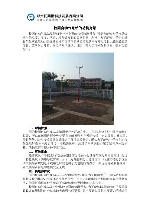
校园自动气象站的功能介绍
校园自动气象站尽管归于一种小型的气候监测设备,可是也能够为学校供给实时的温度、湿度、风速、风向等方面的数据监测,此外,为了能够让学生们进行气候实践活动,高质量的校园自动气象站还能配备干湿球温度计、最高最低温度计、玻璃钢百叶箱、电接风向风速仪、日照计等人工气候观测仪器,基本功能如下:
一、耐候性强
因为校园自动气象站是运用于户外环境之中,并且是对气候条件进行检测的仪器,所以在运用进程中势必要直接触摸到各种天然气候,例如雷雨、暴风雪、烈日等等。
这些气候状况会导致运用环境比较恶劣,所认为了能够让学校主动气候站能够在各种恶劣环境中安稳的运转,选用了不锈钢轻金属支架和户外防护箱,确保能够习惯各种不良气候。
二、可防雷击
通常状况下学校主动气候站校园自动气象站会设备在较为开阔的高地,而这一特色决议了简略导致雷击,因而,为例能够防止遭受雷击,质量安稳的学校主动气候站在规划电子线路之时就选用了先进的防雷办法,并运用电磁兼容规划,让气候站在雷电中也能安全无虞。
三、供电多样化
因为校园自动气象站具有必定的特别性,所认为了能确保在任何状况都能够保持安稳的作业,校园自动气象站供给了市电、直流电以及太阳能等多种供电方法,因而可确保在什么状况下都能够继续无断电的稳态作业。
校园自动气象站是一种比较特别的检测设备,为了能够满意运转的正常需求该设备在规划的时分就充沛考虑到气候要素、雷电要素以及供电要素,经过运用
适合的资料和保护办法来确保其能够一向供给高质量的气候监测。
郑州托莱斯一体化气象站的功能分析
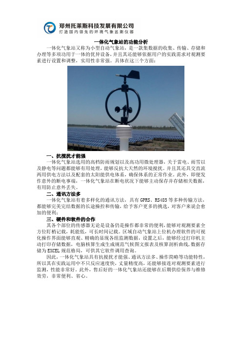
一体化气象站的功能分析
一体化气象站又称为小型自动气象站,是一款集数据的收集、传输、存储和办理等多项功用于一体的优异设备,并且其还能够依据用户的实践需求对观测要素进行设置和调整,实用性非常强。
具体在这三个方面:
一、抗搅扰才能强
一体化气象站选用的高档防雨规划以及高功用微处理器,关于雷电、雨雪以及静电等问题都能够有用处理,能够反抗大天然的环境搅扰。
并且其还具交直流两用供电方法以及配套的太阳能供电体系,确保体系的正常作业。
此外,即便发作意外的断电事端,一体化气象站在断电状况下能够主动保存并存储相关数据,有用防止意外丢失。
二、通讯方法多
一体化气象站有着多样化的通讯方法,具有GPRS、RS485等多种传输方法,都能够完美完结数据的长途操控和传输,给予客户更多的挑选,对客户来说会愈加的便利;
三、硬件和软件的合作
其各个部位的传感器无论是设备仍是操作都非常的便利,能够对观测要素全方位盯梢记载,耗能低,可长时间记载。
区域自动气象站上位机办理软件的可视化操作界面能够直观、精确的显现各组监测数据,设置之后,能够经过打印机主动打印存储数据,电脑核算生成生成规范气候图文报表及核算剖析曲线,数据存储为EXCEL规范格局,可供其它软件调用查询。
因此,一体化气象站具有抗搅扰才能强、通讯方法多、操作简略等功能特性,所以其在实践运用中不只反应速度快,丈量精度高,还能够接连对观测要素进行监测,性能非常好。
此外,售后好的一体化气象站还能够在后期供给保养与维修效劳,非常便利、省心。
温湿度传感器使用说明书

NO:S1*******使用说明书温湿度传感器目录1、产品介绍 (1)1.1概述 (1)1.2功能特点 (1)1.3外观尺寸 (1)2、性能参数 (2)3、使用方法 (4)3.1系统框架图 (4)3.2安装说明 (6)4、通信协议 (9)4.1通讯基本参数 (9)4.2数据帧格式定义 (9)4.3通讯基本参数 (11)4.4通讯协议示例以及解释 (12)5、常见问题及解决方法 (14)6、保养维护 (15)7、运输存储 (16)7.1运输要求 (16)7.2存储要求 (16)8、订货服务 (17)8.1订货方法 (17)8.2客户服务 (17)1产品介绍1.1概述本(系列)产品可在线监测环境温度和湿度信息,广泛用于开关柜仪表室、断路器室、电缆室等处的环境温湿度在线监测。
采用进口工业级微处理器芯片、进口高精度温度传感器,确保产品高精度和可靠性。
1.2功能特点◆进口的测量单元,测量精准。
◆专用的485电路,通信稳定。
◆宽电压范围供电,安装方便。
1.3外观尺寸(单位:mm公差:±0.5)2性能参数3使用方法3.1系统框架图本产品也可以多个传感器组合在一条485总线使用,理论上一条总线可以接254个485传感器,另一端接入带有485接口的PLC 、通过485接口芯片连接单片机,或者使用USB转485即可与电脑连接,使用我公司提供的传感器配置工具进行配置和测试(在使用该配置软件时只能接一台设备)。
3.2安装说明3.2.1注意事项1、传感器应尽量垂直放置,保证安装墙面时,温湿度探头在传感器本体的下方(传感器本体上的字体为正方向)。
2、安装高度为人体坐高或主要测量的环境区域。
3、避免在易于传热且会直接造成与待测区域产生温差的地带安装,否则会造成温湿度测量不准确。
4、安装在环境稳定的区域,避免直接光照,远离窗口及空调、暖气等设备,避免直对窗口、房门。
5、尽量远离大功率干扰设备,以免造成测量不准确,如变频器/电机等。
郑州托莱斯农业气象站的基本组成部分

农业气象站的基本组成部分
气象环境是我们生存空间的一种天然体现,而为了让农人对气象环境有更深层次的了解,许多农田实验基地都建设了农业气象站,经过各种设备对气象进行检测,让其能够充沛满意气象科普教育效劳的需求。
那么高质量的农业气象站首要包含以下3个部分:
一、气象数据收集器
要对气象进行检测,必要收集设备周围的各种数据,包含温度、湿度、风向、风力等等。
而要对其进行有用的收集,田间自动气象站就需求运用到高质量的气象数据收集器,并且在运用的进程中要确保气象数据收集器中没有其他任何杂物,不然将会影响到收集数据的精确性。
二、数据处理器
要想精确的获悉当时的温度、风力等状况,安稳的农业气象站就要将气象数据收集器收集到的数据供给给数据处理其进行剖析,而数据处理器则选用了先进的建模方法,能够对各种数据进行精确的导入、剖析和输出,以便确保能够满意学校完结气象科普教育的要求。
三、雨量传感器
为了能够让农业气象站精确的获悉下雨量的大小状况,在其间运用了雨量传感器。
在下雨时雨量传感器会经过雨水触摸传感器的密布度、速度和频率等方面来对雨量进行核算剖析。
在运用进程中,为了能让雨量传感器保持极为灵敏的传感功用,必定要常常查看,防止有灰尘、杂草等杂物堵塞在雨量传感器的管道之中。
除了这些直接供给气象环境数据剖析的部件之外,为了能让农业气象站能够长时间保持安稳的运转,还有布局合理的电路体系设备,能够为农业气象站供给所需的电力动力,然后让气象站能更好的为气象科普供给效劳。
气象百叶箱LH-MPBOX系列 说明书

气象百叶箱说明书适用型号:LH-MPBOX系列修订记录:目录1.产品介绍 (2)2.规格参数 (2)3.产品尺寸 (3)4.485通信协议与数据格式 (5)4.1.通讯基本参数 (5)4.2.数据帧格式定义 (5)4.3.寄存器地址 (6)4.4.参数读取 (7)5.电气接线 (11)6.售后服务 (11)6.1.售后服务承诺 (11)6.2.免责声明 (11)6.3.联系方式 (12)1.产品介绍气象百叶箱是一种固定式的多合一地面自动观测气象设备,观测项目主要包括气温、湿度、大气压、光照度、二氧化碳浓度、PM2.5、PM10、噪声等多种气象要素。
气象百叶箱可以广泛应用于城市环境测量、农业监控、工业治理等多种环境,以便采集到更加丰富有效的监测数据。
2.规格参数3.产品尺寸图3.1设备由底部的三个安装螺丝固定,客户可以使用螺丝固定百叶箱设备,固定孔如下图所示位置。
安装位置需要注意以下事项:1、变送器应尽量水平安防,保证安装垂直于水平面。
2、安装高度为人体坐高或主要要求测量的环境区域。
同时请注意以下防范事项:1、避免在易于传热且会直接造成与待测区域产生温差的地带安装,否则会造成温湿度测量不准确。
2、安装在环境稳定的区域,避免直接光照,远离窗口及空调、暖气等设备,避免直对窗口、房门。
3、尽量远离大功率干扰设备,以免造成测量的不准确,如变频器、电机等。
4.485通信协议与数据格式4.1.通讯基本参数4.2.数据帧格式定义采用Modbus-RTU通询规约,格式如下:地址码=1字节功能码=1字节数据区=N字节错误校验=16位CRC码结束结构>=4字节的时间地址码:为设备的地址,在通询网络中是唯一的。
功能码:主机所发指令功能提示。
数据区:数据区是具体通询数区,注意16bits数据高字节在前。
CRC码:二字节的校验码。
地址码功能码寄存器起始地址寄存器长度校验码低位校验码高位问询1字节1字节2字节2字节1字节1字节地址码功能码有效字节数数据区校验码低位校验码高位应答1字节1字节1字节2字节1字节1字节4.3.寄存器地址4.4.参数读取(1)例:读取设备地址为01的传感器波特率地址码功能码起始地址数据长度校验码低位校验码高位问询0x010x030x01,0x010x00,0x010xD40x36地址码功能码字节数数据值校验码低位校验码高位应答0x010x030x020x00,0x020x780x35此时,查询到设备的波特率为02,由寄存器表格可知此时02对应9600(2)例:修改设备波特率9600为4800地址码功能码起始地址修改数据校验码低位校验码高位问询0x010x060x01,0x010x00,0x010x090xF7地址码功能码起始地址修改数据校验码低位校验码高位应答0x010x060x01,0x010x00,0x010x090xF7(3)例:查询设备地址地址码功能码起始地址数据长度校验码低位校验码高位问询0x010x030x01,0x000x00,0x010x850xF6地址码功能码字节数数据值校验码低位校验码高位应答0x010x030x020x00,0x010x780x35(4)例:修改设备地址01为02地址码功能码起始地址数据长度校验码低位校验码高位问询0x010x060x01,0x000x00,0x020x090xF7地址码功能码字节数数据值校验码低位校验码高位应答0x010x060x01,0x000x00,0x020x090xF7返回正确应答会修改地址成功,下一条modbus指令,地址自动变为02。
湿度传感器用户手册说明书

TFX120-SCustomizable Fail-Safe actuator forcontrolling dampers in typical commercial HVAC applications.• Torque motor 22 in-lb [2.5 Nm]• Nominal voltage AC 100...240 V • Control On/Off • 1x SPDTTechnical dataElectrical dataNominal voltageAC 100...240 V Nominal voltage frequency 50/60 Hz Nominal voltage rangeAC 85...265 V Power consumption in operation 2.5 W Power consumption in rest position 1.3 W Transformer sizing 5 VAAuxiliary switch1x SPDT, 1 mA...3 A (0.5 A inductive), DC 5 V...AC 250 V, adjustable 0...95°Switching capacity auxiliary switch 1 mA...3 A (0.5 A inductive), DC 5 V...AC 250 V Electrical Connection (2) 18 GA appliance cables, 1 m, 3 m or 5 m, with or without 1/2" NPT conduit connectors Overload Protection electronic throughout 0...95° rotation Electrical Protectionactuators are double insulated Functional dataTorque motor22 in-lb [2.5 Nm]Direction of motion motor selectable by ccw/cw mounting Direction of motion fail-safe reversible with cw/ccw mounting Angle of rotation Max. 95°Angle of rotation note adjustable with mechanical stop Running Time (Motor)75 sRunning time fail-safe <25 s @ -4...122°F [-20...50°C], <60 s @ -22°F [-30°C]Noise level, motor 50 dB(A)Noise level, fail-safe 62 dB(A)Position indicationMechanical Safety dataDegree of protection IEC/EN IP42Degree of protection NEMA/UL NEMA 2Enclosure UL Enclosure Type 2Agency ListingcULus acc. to UL60730-1A/-2-14, CAN/CSA E60730-1:02CE acc. to 2014/30/EU and 2014/35/EU Quality Standard ISO 9001UL 2043 CompliantSuitable for use in air plenums per Section 300.22(C) of the NEC and Section 602 of the IMCAmbient humidity Max. 95% RH, non-condensing Ambient temperature -22...122°F [-30...50°C]Storage temperature -40...176°F [-40...80°C]Servicingmaintenance-free WeightWeight1.6 lb [0.72 kg]TFX120-SFootnotesApplicationOperationTypical specificationMaterialsHousing material UL94-5VA†Rated Impulse Voltage 4kV, Type of Action 1.AA.B, Control Pollution Degree 3.Product featuresFor On/Off, fail-safe control of dampers in HVAC systems. Actuator sizing should be done in accordance with the damper manufacturer’s specifications. Control is On/Off from an auxiliary contact, or a manual switch. The actuator is mounted directly to a damper shaft from 1/4” up to 1/2” in diameter by means of its universal clamp, 1/2” shaft centered at delivery. A crank arm and several mounting brackets are available for applications where the actuator cannot be direct coupled to the damper shaft.The TF series actuators provide true spring return operation for reliable fail-safe application and positive close off on air tight dampers. The spring return system provides consistent torque to the damper with, and without, power applied to the actuator. The TF series provides 95° of rotation and is provided with a graduated position indicator showing 0° to 90°. The actuator may be stalled anywhere in its normal rotation without the need of mechanical end switches. Power consumption is reduced in holding mode. The actuator is double insulated so anelectrical ground connection is not necessary. The TF-S versions are provided with one built-in auxiliary switch. This SPDT switch is provided for safety interfacing or signaling, for example, for fan start-up. The switching function is adjustable between 0° and 95°.Safety Note: Screw a conduit fitting into the actuator’s bushing. Jacket the actuator’s input and output wiring with suitable flexible conduit. Properly terminate the conduit in a suitable junction box.On/Off spring return damper actuators shall be direct coupled type which require no crank arm and linkage and be capable of direct mounting to a shaft up to a 1/2” diameter and center a 1/2” shaft. The actuators must be designed so that they may be used for either clockwise or counter clockwise fail-safe operation. Actuators shall be protected from overload at all angles ofrotation. If required, one SPDT auxiliary switch shall be provided having the capability of being adjustable. Actuators with auxiliary switch must be constructed to meet the requirements for Double Insulation so an electrical ground is not required to meet agency listings. Actuators shall be cULus listed, have a 5 year warranty, and be manufactured under ISO 9001 International Quality Control Standards. Actuators shall be as manufactured by Belimo.AccessoriesElectrical accessoriesDescriptionType Auxiliary switch, mercury-free P475Auxiliary switch, mercury-freeP475-1Signal simulator, Power supply AC 120 V PS-100Cable conduit connector 1/2"TF-CC USTFX120-SMechanical accessoriesDescriptionType Shaft extension 170 mm ø10 mm for damper shaft ø6...16 mm AV6-20Position indicator for TFB(X)IND-TF Shaft clamp for TFB(X)K8 USBall joint suitable for damper crank arm KH8 / KH10KG10A Ball joint suitable for damper crank arm KH8KG6Ball joint suitable for damper crank arm KH8KG8Damper crank arm Slot width 8.2 mm, for ø1.05"KH12Damper crank arm Slot width 6.2 mm, clamping range ø10...18 mm KH6Damper crank arm Slot width 8.2 mm, clamping range ø10...18 mm KH8TFB(X) crankarm with 5/16" slot.KH-TF US TFB(X) crankarm with 1/4" slot.KH-TF-1 US Screw fastening kitSB-TF Push rod for KG10A ball joint 36” L, 3/8” diameterSH10Push rod for KG6 & KG8 ball joints (36” L, 5/16” diameter).SH8Anti-rotation bracket TF/NKQ/AM/NM/LM.TF-P Wrench 0.32 in and 0.39 in [8 mm and 10 mm]TOOL-06Angle of rotation limiter, with end stop ZDB-TF Mounting bracket for TFB(X)ZG-113Damper clip for damper blade, 3.5” width.ZG-DC1Damper clip for damper blade, 6” width.ZG-DC2Shaft extension for 3/8" diameter shafts (4" L).ZG-LMSA-1Shaft extension for 1/2" diameter shafts (5" L).ZG-LMSA-1/2-5TFB(X) crankarm adaptor kit (includes ZG-113).ZG-TF112TFB(X) crankarm adaptor kit (T bracket included).ZG-TF2Mounting kit for TFB(X)ZG-TF3Weather shield 13x8x6" [330x203x152 mm] (LxWxH)ZS-100Baseplate, for ZS-100ZS-101Weather shield 406x213x102 mm [16x8-3/8x4"] (LxWxH)ZS-150Electrical installationWarning! Live electrical components!During installation, testing, servicing and troubleshooting of this product, it may be necessary to work with live electrical components. Have a qualified licensed electrician or other individual who has been properly trained in handling live electrical components perform these tasks. Failure to follow all electrical safety precautions when exposed to live electrical components could result in death or serious injury.Meets cULus requirements without the need of an electrical ground connection.Apply only AC line voltage or only UL-Class 2 voltage to the terminals of auxiliary switches. Mixed or combined operation of line voltage/safety extra low voltage is not allowed.Actuators with appliance cables are numbered.Provide overload protection and disconnect as required.Actuators may be connected in parallel if not mechanically linked. Power consumption and input impedance must be observed.One built-in auxiliary switch (1x SPDT), for end position indication, interlock control, fan startup, etc.Wiring diagrams On/OffAuxiliary SwitchesTFX120-S Dimensions。
Series WHT 天气抗性湿度 温度传感器说明书

The compact Series WHT Weather-Resistant Humidity/Temperature Transmitter is designed to withstand the elements. A removable sintered filter protects the polymer capacitance sensor from solid objects that may come in contact with the transmitter. The transmitter is available with 4-20 mA or 0-10 VDC output signals for both temperature and humidity. This transmitter is ideal for measuring outside air temperature and humidity levels for air handling economizer applications.• Easy installation into tight spaces with compact NEMA 3S housing• Reduced installation costs with combination RH and temperature outputs as required• Air handling economizers• Air environment monitoring in agriculture or livestock cultivation housesBENEFITS/FEATURESDESCRIPTIONAPPLICATIONSSERIES WHT |WEATHER-RESISTANT HUMIDITY/TEMPERATURE TRANSMITTER®SPECIFICATIONSRelative Humidity Range0 to 100% RH.Temperature Range-40 to 140°F (-40 to 60°C).Accuracy, RH±3% 20 to 80% RH, ±4% @ 10-20%, 80 to 90%.Accuracy, Temp Models with 4-20 mA Temp. Output ±0.9°F @ 72°F (±0.3°C @ 25°C).Accuracy, Temp Models with Passive Thermistor Temp Sensor±0.36°F @ 77°F (±0.2°C @ 25°C).Hysteresis, RH ±1%.Repeatability, RH ±0.1% typical.Temperature Limits-40 to 140°F (-40 to 60°C).Compensated Temperature Range, RH-4 to 140°F (-20 to 60°C).Power Requirements4-20 mA loop powered models: 10-35 VDC; 0-10 V output models: 15-35 VDC or 15-29 VAC; 0-5 V output models: 10-35 VDC or 10-29 VAC.Output Signal4-20 mA loop powered models: 4-20 mA; 0-10 V output models: 0-10 V @ 5 mA max; 0-5 V output models: 0-5 V @ 5 mA max.Response Time15 s.Electrical ConnectionsRemovable screw terminal block.Drift<1% RH/year.RH SensorCapacitance polymer.Temperature Sensor4-20 mA output, solid state band gap. Passive output: 10K @ 25°C thermistor (Dwyer curve A).EnclosureABS.Enclosure RatingDesigned to meet NEMA 3S (IP54).Weight0.3 oz (8.5 g).Agency ApprovalsCE.©Copyright 2021 Dwyer Instruments, Inc.Printed in U.S.A. 7/21DS-WHT Rev. 1ORDER ONLINE TOD DWYER INSTRUMENTS, INC.Important Notice: Dwyer Instruments, Inc. reserves the right to make changes to or discontinue any product or service identified in this publication without notice. Dwyer advises its customers to obtain the latest version of the relevant information to verify, before placing any orders, that the information being relied upon is current.DIMENSIONSWIRING DIAGRAMHOW TO ORDERSERIESWHT: Weather-resistant humidity/temperature transmitter RH OUTPUT -31: 4-20 mA -32: 0-10 VDC -33: 0-5 VDCWHT-31Use the bold characters from the chart below to construct a product code.Models with 4-20 mA RH output,with or without 4-20 mA temperature output Models with 0-5 V or 0-10 V RH output,with or without 0-5 V or 0-10 V temperature outputModels with 4-20 mA RH outputand a passive thermistor temperature sensor Models with 0-5 or 0-10 V RH output and a passive thermistor temperature sensorTEMPERATURE 0: None 1: 4-20 mA 2: 0-10 VDC 3: 0-5 VDCA: 10K Ω type IIITEMP. RECEIVER +–+–RH RECEIVERPOWER SUPPLY+–1 2 3 41 2 3 4TEMP. SENSOR +–RH RECEIVERPOWER SUPPLY+–POWER SUPPLY+–TEMP. RECEIVER +–+–RH RECEIVER 1 2 3 4 5WIRING TEMP. SENSOR+–RH RECEIVER POWER SUPPLY+–2X 5/16 [7.94]4[101.6]3-31/64[88.5]3[76.2]4-9/16[115.89]2-3/4[69.85]1-31/64[37.70]1-27/64[36.12]。
湿度温度传感器系统说明书

Mounting Cont'd.DIN Rail Mounting Bracket InstallationInput ConnectionThe UWRH can provide fast, accurate readings from aHumidity Probe with a M12 8 pin connector.Input Diagram for M12 8-pin ConnectorBattery ReplacementTo install or replace the battery in your device you must first loosen the one screw located on the lid of the enclosure. This will allow you to access the battery compartment.Your device is equipped with a “C” size lithium power cell assembly. To install a replacement battery assembly follow steps outlined here.A. Remove the old power cell from the battery holder.B. I nstall your new battery assembly into the housing in the same position as the old battery was located.C. Installation complete.WGS/START HERE ARRO 5WGS/START HERE ARRO6UWRH-2A-NEMA-M12, UWRH-2A-NEMA-M12-CABLE,Weather Resistant Wireless Relative Humidity/Temperature TransmitterMQS5044A-RH/0913System OperationA basic wireless RH system is comprised of only two main components; a signal conditioner with a built-in battery powered 2.4 GHz radio transmitter (End Device), and a USB powered 2.4 GHz radio receiver.End Device/ReceiverTransmit Rate vs. Battery LifeMany factors such as ambient temperature conditions and transmitting rate can have a large effect on the life of the battery used in your end device. Transmitting data places a large demand on the battery in your unit. The transmit rate is the single most contributing factor in the life of your battery. The slower the transmit rate you set, the longer the battery in your device will last. The table below gives some estimates on how long the battery should last vs. the transmit rate you selected when you setup your end device and under normal operating conditions. Transmission IntervalBattery Life (Months)2 Seconds 4 10 Seconds 7.5 30 Seconds 16.560 Seconds30SpecificationsTemperature Range: -17 to 49°C (2 to 120°F)/manuals/manualpdf/M5044-RH.pdf***********************®It is the policy of OMEGA Engineering, Inc. to comply with all worldwide safety and EMC/EMI regulations that apply. OMEGA is constantly pursuing certification of its products to the European New Approach Directives. OMEGA will add the CE mark to every appropriate device upon certification.The information contained in this document is believed to be correct, but OMEGA accepts no liability for any errors it contains, and reserves the right to alter specifications without notice.WARNING: These products are not designed for use in, and should not be used for, human applications.WARRANTY/DISCLAIMEROMEGA ENGINEERING, INC. warrants this unit to be free of defects in materials and workmanship for a period of 13 months from date of purchase. OMEGA’s WARRANTY adds an additional one (1) month grace period to the normal one (1) year product warranty to cover handling and shipping time. This ensures that OMEGA’s customers receive maximum coverage on each product.If the unit malfunctions, it must be returned to the factory for evaluation. OMEGA’s Customer Service Department will issue an Authorized Return (AR) number immediately upon phone or written request. U pon examination by OMEGA, if the unit is found to be defective, it will be repaired or replaced at no charge. OMEGA’s WARRANTY does not apply to defects resulting from any action of the purchaser, including but not limited to mishandling, improper interfacing, operation outside of design limits, improper repair, or unauthorized modification. This WARRANTY is VOID if the unit shows evidence of having been tampered with or shows evidence of having been damaged as a result of excessive corrosion; or current, heat, moisture or vibration; improper specification; misapplication; misuse or other operating conditions outside of OMEGA’s control. Components in which wear is not warranted, include but are not limited to contact points, fuses, and triacs.OMEGA is pleased to offer suggestions on the use of its various products. However, OMEGA neither assumes responsibility for any omissions or errors nor assumes liability for any damages that result from the use if its products in accordance with information provided by OMEGA, either verbal or written. OMEGA warrants only that the parts manufactured by the company will be as specified and free of defects. OMEGA MAKES NO OTHER WARRANTIES OR REPRESENTATIONS OF ANY KIND WHATSOEVER, EXPRESSED OR IMPLIED, EXCEPT THAT OF TITLE, AND ALL IMPLIED WARRANTIES INCLUDING ANY W ARRANTY OF MERCHANTABILITY AND FITNESS FOR A PARTICULAR PURPOSE ARE HEREBY DISCLAIMED. LIMITATION OF LIABILITY: The remedies of purchaser set forth herein are exclusive, and the total liability of OMEGA with respect to this order, whether based on contract, warranty, negligence, indemnification, strict liability or otherwise, shall not exceed the purchase price of the component upon which liability is based. In no event shall OMEGA be liable for consequential, incidental or special damages.CONDITIONS: Equipment sold by OMEGA is not intended to be used, nor shall it be used: (1) as a “Basic Component” under 10 CFR 21 (NRC), used in or with any nuclear installation or activity; or (2) in medical applications or used on humans. Should any Product(s) be used in or with any nuclear installation or activity, medical application, used on humans, or misused in any way, OMEGA assumes no responsibility as set forth in our basic WARRANTY/DISCLAIMER language, and, additionally, purchaser will indemnify OMEGA and hold OMEGA harmless from any liability or damage whatsoever arising out of the use of the Product(s) in such a manner.RETURN REQUESTS/INQUIRIESDirect all warranty and repair requests/inquiries to the OMEGA Customer Service Department. BEFORE RETU RNING ANY PRODU CT(S) TO OMEGA, PU RCHASER MU ST OBTAIN AN AUTHORIZED RETURN (AR) NUMBER FROM OMEGA’S CUSTOMER SERVICE DEPARTMENT (IN ORDER TO AVOID PROCESSING DELAYS). The assigned AR number should then be marked on the outside of the return package and on any correspondence.FOR WARRANTY RETURNS,please have the followinginformation available BEFOREcontacting OMEGA:1. Purchase Order number underwhich the product was P U RCHASED, 2. Model and serial number of the product under warranty, and 3. Repair instructions and/orspecific problems relative tothe product.FOR NON-WARRANTY REPAIRS, consult OMEGA for current repair charges. Have the following information available BEFORE contacting OMEGA:1. Purchase Order number tocover the COST of the repair or calibration,2. Model and serial number of theproduct, and 3. R epair instructions and/or specific problems relative to the product.OMEGA’s policy is to make running changes, not model changes,whenever an improvement is possible. This affords our customers the latest in technology and engineering.OMEGA is a registered trademark of OMEGA ENGINEERING, INC.© Copyright 2013 OMEGA ENGINEERING, INC. All rights reserved. This document may not be copied, photocopied, reproduced, translated, or reduced to any electronic medium or machine-readable form, in whole or in part, without the prior written consent of OMEGA ENGINEERING, INC.Patented: Covered by U.S. and International Patents and Patents Pending.The “Welcome to the TC Central Setup Wizard” screen should be visible on your computer screen. The installer will guide you through the steps required to install TC Central on your computer.Device ConfigurationFirst, connect the provided USB cable to yourconnector/transmitter unit and also to an available USB port on your computer.Now that you have connected your USB cable to your PC and transmitter you will complete the following steps to configure your device beforeplacing the unit into operation. You will be using the configuration software utility (TC Central>>End Device Configuration Wizard) that you installed onto your PC in the previous section. If you have not installed the configuration software utility you should do so now. During this procedure you will be setting the following parameters in your transmitter.Button Operation 1. “ON/OFF”The “ON/OFF” button on the front of your connector/transmitter is used to turn your unit “ON” or “OFF”.2. “SETUP”The “SETUP” button on the front of your connector/transmitter is only used during the setup and configuration of your unit.Indicator Lights1. Transmit (TX) Green Indicator LightThe green indicator light marked “TX” on the front of your connector/transmitter will blink every time the unit sends data to the receiving unit. Example: If you selected a 5 second sample rate the green TX LED will blink one time every 5 seconds.2. Low Battery (Low Bat) Red Indicator LightThe red indicator light marked “Low Bat” on the front of the connector/transmitter will turn on when the battery reaches a level at or below the power level required for normal operation. When this indicator turns on it’s time to install a fresh battery in your unit. For procedures on how to change your battery see the later section Battery ReplacementChannel NumberThis sets a unique address number into yourtransmitter. Later, when you set up your measurement software you will again set channel numbers to receive readings from the corresponding unit(s). Each unit must be set for a different channel number for your system tooperate correctly.WGS/START HERE ARROWGS/START HERE ARRO 2WGS/START HERE ARRO34Using This Quick Start Manual Use this Quick Start Manual with your UWRH-2A-NEMA –M12 Weather Resistant Wireless Relative Humidity/Temperature Transmitter for quick installation and basicoperation. For detailed information, refer to the User’s Guide (Manual # M5044)General DescriptionThe UWRH-2A-NEMA-12 and UWRH-NEMA-M12-CABLE Weather Resistant Wireless Relative Humidity/Temperature Transmitter feature a standalone, compact, battery powered NEMA rated design that transmits measurements back to a host receiver up to 120m (400’) away. When activated the wireless transmitter will transmit readings continuously at a pre-set time interval that was programmed by the user during initial setup. Each unit measures and transmits: Relative Humidity Reading, Ambient Temperature, RF Signal Strength and Battery Condition to thereceiver and is displayed on your PC in real time using the provided software.Main Transmitter BoardSoftware InstallationSystem Minimum Requirements:• Pentium Class processor • Hard Drive Space: 210 MB • RAM: 256 MB • 1 Available USB Port • 1 CD-ROM Drive• Windows 2000, XP , Vista, 7Insert the TC-Central User CD that was included with your receiver unit into the CD-ROM drive of your PC. Your system should begin the installation process Sample Rate:This will program your device to transmit 1 data reading to your receiver at a specified time interval. Available settings are 2, 3, 5, 15, 30, 45, 60, 75 or 90.STEP 1. Enter the “SETUP” mode.To place your transmitter into the “SETUP” mode for programming follow this procedure:Press and hold the “ON/OFF” button. While the “ON/OFF” button is being held, press the “SETUP” button one time and then release the “ON/OFF” button. The green (TX) indicator on the front of your device should be blinking at a steady rate. This indicates that your device is ready to run the configuration utility software.(Refer to Main Transmitter Board diagram for button locations)STEP 2. Launch Setup Utility Program.To launch the End Device Configuration Wizard, begin by accessing the “Programs” list under your “Start Menu”.Scroll through the list to find the Omega “TC-Central” folder, and then select the End Device Configuration Wizard.STEP 3. Programming the device settings .After starting the setup utility program, the ”Welcome to the Universal Wireless End Device Configuration Wizard” screen should be visible on your screen. The software will guide you through the steps required to program your device settings.Device InstallationWhen installing your device it is important to position your device in such a way as to optimize the antenna location within what is known as the “Fresnel Zone”.The Fresnel Zone can be thought of as a football-shaped invisible tunnel between two locations that provides a path for RF signals between your deviceIn order to achieve maximum range, the football-shaped path in which radio waves travel must be free of all obstructions. Obstacles in the path (especiallymetal) will decrease the communication rangebetween your device and your receiver. Also, if the antennas are mounted just barely off the ground, over half of the Fresnel zone ends up being obstructed by the earth resulting in significant reduction in range. To avoid this problem, the antennas should be mounted high enough off of the ground so that the earth does not interfere with is allowed. By definition co-location is when another radio device or the device's antenna is located within 20 cm of your connector/transmitter and can transmit simultaneously with your unit.MountingWhen mounting your end device, care should be taken to make sure it is as far away from any metal objects. If nearby metal gets too close to your unit, it has the potential to interfere with the way the unit radiates and may cause signal loss or possibly even the inability to communicate at all with yourTo install the DIN Rail Mounting Bracket accessory (UWM-DINRAIL) you must first remove the one screw located on the lid of the enclosure. This will allow you access to the mounting holes.Place all four #4-40 screws with threaded standoffs into each mounting hole. Screw on the DIN Rail Mounting Bracket sub assembly including the DIN Rail Adaptors to the bottom of the enclosure using the #4-40 screws.Close the unit by threading the one screw located on the lid of the enclosure to the bottom enclosure.。
湿度传感器产品说明书.pdf_1718742584.1268241
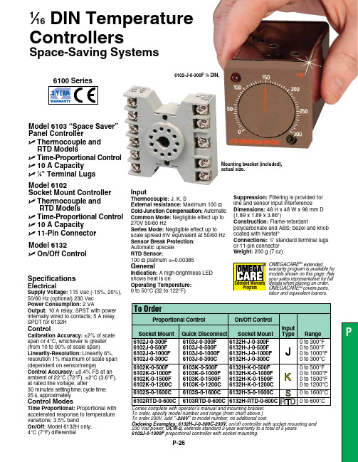
P-26To order, specify model number and range (from chart above.) To order 230V, add “-230V” to model number, no additional cost.Ordering Examples: 6132H-J-0-300C-230V, on/off controller with socket mounting and230 Vac power. OCW-2, extends standard 3-year warranty to a total of 5 years. 6102J-0-1000F proportional controller with socket mounting.Specifications Electrical Supply Voltage: 115 Vac (-15%, 20%), 50/60 Hz (optional) 230 Vac Power Consumption: 2 VAOutput: 10 A relay, SPST with power internally wired to contacts; 5 A relay, SPDT for 6132H Control Calibration Accuracy: ±2% of scale span or 4°C, whichever is greater (from 10 to 90% of scale span)Linearity-Resolution: Linearity 6%, resolution 1% maximum of scale span (dependent on sensor/range)Control Accuracy: ±0.4% FS at anambient of 22°C (72°F); ±2°C (3.6°F), at rated line voltage, after 30 minutes setting time; cycle time: 25 s, approximately Control Modes Time Proportional: Proportional with accelerated response to temperature variations; 3.5% band On/Off: Model 6132H only; 4°C (7°F) differentialModel 6103 “Space Saver” Panel ControllerU T hermocouple andRTD Models U T ime-Proportional Control U 10 A Capacity U 1⁄4" Terminal LugsInput Thermocouple:J, K, S External resistance: Maximum 100 ΩCold-Junction Compensation: AutomaticCommon Mode: Negligible effect up to 270V 50/60 Hz Series Mode: Negligible effect up to scale spread mV equivalent at 50/60 Hz Sensor Break Protection: Automatic upscale RTD Sensor: 100 Ω platinum a =0.00385General Indication: A high-brightness LED shows heat is on Operating Temperature: 0 to 50°C (32 to 122°F) Suppression: Filtering is provided for line and sensor input interference Dimensions:48 H x 48 W x 98 mm D(1.89 x 1.89 x 3.86")Construction:Flame-retardantpolycarbonate and ABS; bezel and knob coated with Nextel ®Connections: 1⁄4" standard terminal lugs or 11-pin connector Weight: 200 g (7 oz)Model 6102Socket Mount Controller U T hermocouple and RTD Models U T ime-Proportional Control U 10 A Capacity U 11-Pin Connector Model 6132U O n/Off Control 6102-J-0-300F 1⁄16 DIN.1⁄16 DIN Temperature Controllers Space-Saving SystemsOMEGACARE SMextendedwarranty program is available for models shown on this page. Ask your sales representative for full details when placing an order. OMEGACARE SMcovers parts,labor and equivalent loaners.Mounting bracket (included), actual size.。
湿度传感器产品说明书

36
40
39 38 37
42 43 44 45 ASSY
1
2 3
4
5 5
4
29 28
27 26
31 ASSY
DETAIL A
34
7 8
6
DETAIL B
30
46 GSKT
32 33
47
25 ASSY
9
DETAIL C
24 23
18
16 17
10
21
20 ASSY
Pg.2 REV: -00 REV DATE: 3/2/15
SCRW 8-32X5/8 PH CUT 410
3 SNAP DISC 150-130
COOL DOWN SWITCH NO F150
1 GSKT 1MCS
MED CELL SIL FOAM GSKT 1X.25X20'PSA
1 59672
BAY BLOWER END SEAL CAP
1 Z-600-3850
35 36 37 38 39 40 41 42 43 44 45
*46 *46(a) *46(b)
47 48 49 50 51 52 53 54 55 56 57 58 59 60 61 62 63 64 65 66
1 CNTRL PNL PHT
OVERLAY CNTR PNL PHT 4.125X 24"
1 GSKT MAG2531
MAG. DOOR GASKET 25.25 X 30.50
1 GSKT-D-24X29-875
SILICONE GASKET D-24.00X29.875
1 TRNS-240-120-40VA
TS-FTDO2 系列湿度传感器产品使用说明书
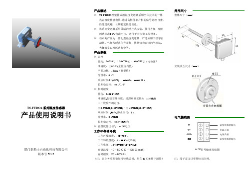
TS-FTDO2系列湿度传感器产品使用说明书厦门泰勒士自动化科技有限公司版本号V1.2产品概述※TS-FTDO2型壁挂式温湿度变送器采用全体技术的一体式温湿度传感模块,通过高性能单片机的信号处理,整机性能更优越,长期稳定性更出色。
※该系列变送器采用灵活的壁挂式安装,使用方便,输出两路标准0-5V直流电压,适用于大多数工控设备。
※该系列产品为一体化温湿度变送器,广泛应用于楼宇自动化、气候与暖通信号采集、博物馆和宾馆的气候站、大棚温室以及医药行业等。
产品参数※温度量程:0~+50℃/-20~+80℃/-40~+60℃(可设置)准确度:±0.3℃(全量程均值)产品功耗:15mA(典型值)分辨率:0.1℃响应时间6τ(63%):min=5s,max=30s长期稳定性:<0.1℃/年※相对湿度量程:0~99.9%RH准确度(包括非线性度,迟滞和重复性):±3%RH工厂校验不确定度:±0.6%RH(0~40%RH)/±1.0%RH(40~97%RH)响应时间(90%)静止空气:8s分辨率:0.1%RH长期稳定性:<0.5%RH/年※温湿度输出信号:0-5V电压工作和存储环境工作环境温度:-40~+80℃工作环境湿度:0~99.9%无冷凝工作电压:15~36VDC/12~24V AC存储温度:10–50°C(0–125°C peak)存储湿度:20–60%RH(注:以上各项参数如没特殊说明,均在25℃条件下测量)外形尺寸整体尺寸(mm)安装法兰尺寸(mm)电气接线图TV+GNDRH0-5V信号输出接线图注:端子定义以实物标识为准。
温度模拟量输出电源正极电源负极湿度模拟量输出电气接线示意图注意:此变送器输出信号为0-5V 直流电压,如采用电压型检测设备,请将检测设备并联接入输出电路中(见典型应用电路中电压表的位置),如采用其它检测设备,请作相应处理。
- 1、下载文档前请自行甄别文档内容的完整性,平台不提供额外的编辑、内容补充、找答案等附加服务。
- 2、"仅部分预览"的文档,不可在线预览部分如存在完整性等问题,可反馈申请退款(可完整预览的文档不适用该条件!)。
- 3、如文档侵犯您的权益,请联系客服反馈,我们会尽快为您处理(人工客服工作时间:9:00-18:30)。
气象百叶箱型温湿度传感器技术说明书
气象百叶箱型温湿度传感器是一款全数字化检测,高精度传感器,气象百叶箱型温湿度传感器是由高精度数字温度、湿度集成,可准确、快速检测出大气温度、大气湿度,内置信号处理单元能根据用户需求输出相应信号,高强度结构设计可在恶劣气候环境中准确检测,可广泛用于气象、海洋、环境、机场、港口、实验室、工农业及交通等领域。
气象百叶箱型温湿度传感器的技术参数:
温度测量范围:-50~100℃,准确度:±0.5℃,分辨率:0.1℃;
湿度测量范围:0~100%RH,准确度:±3%RH(T>0℃),±5%RH(T≤0℃),分辨率:0.1%;
供电方式:DC12~24V
输出方式:RS485,四线制
信号输出:RS-485信号,设备支持ModBus协议(波特率9600可设,地址0-255可设)
存储温度:-50℃~80℃
使用环境:温度-40℃~60℃湿度0~85%
防护等级:IP66。
