HB温湿度传感器变送器系列标准modbus通讯协议使用说明书(北京盛世宏博科技有限公司)
以太网型温湿度 传感器使用说明书
以太网型温湿度传感器使用说明书THVer1.0第1章产品简介1.1产品概述以太网型温湿度传感器是使用以太网进行温湿度传输的传感器,实时测量温湿度,并使用网线进行传输。
设备支持主动上传与TCP Modbus两种形式。
本系列产品充分利用现成的以太网网络实现不限距离的数据采集与传输与集中控制。
1.2功能特点本产品采用瑞士进口高灵敏度数字探头,信号稳定,精度高。
具有测量范围宽、线形度好、防水性能好、使用方便、便于安装、传输距离远等特点。
本产品广泛用于机房监控系统、安防工程、医疗卫生监控、能耗监控系统、智能家居等系统。
1.3主要参数POE供电48V标准POE供电(选配)传输接口RJ4510M/100M自适应1.4温湿度参数(-S20型)1.5探头参数与选型-S30型SHT30±0.3℃±2-4.5% -S31型SHT31±0.3℃±2%-S75型SHT75±0.3℃±1.5-3% 1.6温度参数(-S20型)表一不同温度下温度测量精度如上表所示,在5-60摄氏度范围内最大偏差在±0.5内,小于0℃和大于60摄氏度情况下偏差递增。
1.7湿度参数(-S20型)表二不同湿度下湿度测量精度如上表所示,在20-80%RH范围内典型偏差±3%,小于20%和大于80%的湿度情况下情况下偏差递增。
1.8温度对湿度测量的影响(-S20型)上文表二描述了不同湿度情况对湿度测量的影响,下表描述了不同的温度对湿度测量精度的影响。
表三不同温度下的相对湿度如上所示,在15℃到55℃,30到80的湿度范围内,湿度的精度最高,是±4.5%,其余情况湿度递增。
1.9系统框架图第2章硬件连接2.1设备安装前检查安装设备前请检查设备清单:2.2产品接口样式说明电源圆口DC头12-24V直流供电网口RJ45接口连接10/100M网线如上图所示为普通供电版本设备,分为一个DC口供电口和一个防水RJ45网线口。
Honeywell HumidIcon数字湿度 温度传感器I2C通信技术说明书
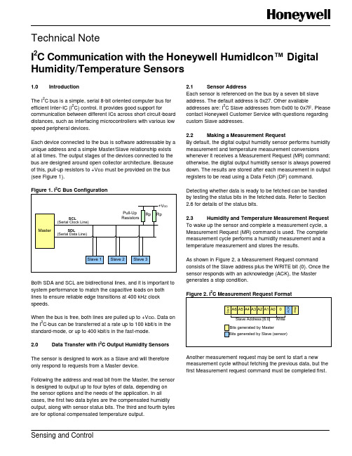
Technical NoteI 2C Communication with the Honeywell HumidIcon™ Digital Humidity/Temperature SensorsSensing and Control1.0 IntroductionThe I 2C bus is a simple, serial 8-bit oriented computer bus forefficient Inter-IC (I 2C) control. It provides good support forcommunication between different ICs across short circuit-board distances, such as interfacing microcontrollers with various low speed peripheral devices.Each device connected to the bus is software addressable by a unique address and a simple Master/Slave relationship exists at all times. The output stages of the devices connected to the bus are designed around open collector architecture. Because of this, pull-up resistors to +V DD must be provided on the bus (see Figure 1).2Both SDA and SCL are bidirectional lines, and it is important to system performance to match the capacitive loads on both lines to ensure reliable edge transitions at 400 kHz clock speeds.When the bus is free, both lines are pulled up to +V DD . Data onthe I 2C-bus can be transferred at a rate up to 100 kbit/s in the standard-mode, or up to 400 kbit/s in the fast-mode.2.0 Data Transfer with I 2C Output Humidity SensorsThe sensor is designed to work as a Slave and will therefore only respond to requests from a Master device.Following the address and read bit from the Master, the sensor is designed to output up to four bytes of data, depending on the sensor options and the needs of the application. In all cases, the first two data bytes are the compensated humidity output, along with sensor status bits. The third and fourth bytes are for optional compensated temperature output.2.1 Sensor AddressEach sensor is referenced on the bus by a seven bit slave address. The default address is 0x27. Other availableaddresses are: I 2C Slave addresses from 0x00 to 0x7F. Please contact Honeywell Customer Service with questions regarding custom Slave addresses. 2.2 Making a Measurement RequestBy default, the digital output humidity sensor performs humidity measurement and temperature measurement conversionswhenever it receives a Measurement Request (MR) command; otherwise, the digital output humidity sensor is always powered down. The results are stored after each measurement in output registers to be read using a Data Fetch (DF) command.Detecting whether data is ready to be fetched can be handled by testing the status bits in the fetched data. Refer to Section 2.6 for details of the status bits. 2.3 Humidity and Temperature Measurement Request To wake up the sensor and complete a measurement cycle, a Measurement Request (MR) command is used. The complete measurement cycle performs a humidity measurement and a temperature measurement and stores the results.As shown in Figure 2, a Measurement Request commandconsists of the Slave address plus the WRITE bit (0). Once the sensor responds with an acknowledge (ACK), the Master generates a stop condition.2Another measurement request may be sent to start a new measurement cycle without fetching the previous data, but the first Measurement request command must be completed first.I 2C Communication with the Honeywell HumidIcon™ Digital Humidity/Temperature Sensors2 Honeywell Sensing and Control2.4 Humidity Data Fetch To read out a compensated humidity reading, the Master generates a START condition and sends the sensor Slave address followed by a read bit (shown in Figure 2). After the sensor generates an acknowledge (ACK), it will transmit up to four bytes of data – the first two bytes containing the compensated temperature output and the second two bytes containing the optional compensated temperature output.The Master must acknowledge the receipt of each byte, and can terminate the communications by sending a Not Acknowledge (NACK) bit followed by a STOP bit after receiving both bytes of data as shown in Figure3.22.5 Humidity and Temperature Data Fetch The optional corrected temperature data is read out with 14 bit resolution. By reading out the third and fourth bytes of data from the sensor, the complete 14 bit optional compensated temperature value may be read. When reading the full 14 bit resolution temperature output, the two least significant bits of the fourth data byte are “Do Not Care” and should be ignored (see Figure 4.)2.6 Status BitsHoneywell digital output humidity sensors offer status bits to ensure robust system operation in critical applications. The sensor status is indicated by the first two Most Significant Bits of Data Byte 1 (see Table 1).When the status bits read “01”, “Stale” data is indicated. This means that the data in the output buffer of the sensor has already been fetched by the master, and has not yet beenupdated with the new data from the current measurement cycle. This can happen when the master polls the data quicker than the sensor can update the output buffer.This mode should not be seen during normal operationI 2C Communication with the Honeywell HumidIcon™ Digital Humidity/Temperature SensorsHoneywell Sensing and Control 33.0 Measurement CycleFigure 5 shows the measurement cycle for the humidity sensor. The measurement cycle duration is typically 36.65 ms for temperature and humidity readings.Figure 5. Measurement Cycle for Humidity and4.0 Calculation of the Humidity from the Digital OutputThe output of the device is simply a 14 bit number representing between 0 %RH and 100 %RH (see Equation 1):0 %RH = 0 counts100 %RH = 214- 2 counts5.0 Calculation of Optional Temperature from the Digital OutputFor sensors with the optional compensated temperature output, the output of the device is simply a 14 bit number representing between -40 C and 125 C (see Equation 2):-40 C = 0 counts125 C = 214- 2 counts6.0Timing and Level Parameters (See Figure 6.)2I2C Communication with the Honeywell HumidIcon™ Digital Humidity/Temperature SensorsSensing and ControlHoneywell1985 Douglas Drive NorthGolden Valley, MN 55422 /sensing 009061-2-ENJune 2012Copyright © 2012 Honeywell International Inc. All rights reserved.PERSONAL INJURYWARRANTY/REMEDYHoneywell warrants goods of its manufacture as being free of defective materials and faulty workmanship. Honeywell’s standard product warranty applies unless agreed to otherwise by Honeywell in writing; please refer to your order acknowledgement or consult your local sales office for specific warranty details. If warranted goods are returned to Honeywell during the period of coverage, Honeywell will repair or replace, at its option, without charge those items it finds defective. The foregoing is buyer’s sole remedy and is in lieu of all other warranties, expressed or implied, including those of merchantability and fitness for a particular purpose. In no event shall Honeywell be liable for consequential, special, or indirect damages.While we provide application assistance personally, through our literature and the Honeywell web site, it is up to the customer to determine the suitability of the product in the application.Specifications may change without notice. The information we supply is believed to be accurate and reliable as of this printing. However, we assume no responsibility for its use.MISUSE OF DOCUMENTATIONThe information presented in this technical note is forreference only. DO NOT USE this document as a product installation guide.Complete installation, operation, and maintenanceinformation is provided in the instructions supplied witheach product.Failure to comply with these instructions could result in death or serious injury.SALES AND SERVICEHoneywell serves its customers through a worldwide network of sales offices, representatives and distributors. For application assistance, current specifications, pricing or name of the nearest Authorized Distributor, contact your local sales office or:E-mail:*********************Internet: /sensingPhone and Fax:Asia Pacific +65 6355-2828+65 6445-3033 FaxEurope +44 (0) 1698 481481+44 (0) 1698 481676 FaxLatin America +1-305-805-8188+1-305-883-8257 FaxUSA/Canada +1-800-537-6945+1-815-235-6847+1-815-235-6545 Fax。
基于MODBUS协议的温湿度检测模块设计_毕业设计

基于MODBUS协议的温湿度检测模块设计目录摘要 (1)关键词 (1)1 前言 (2)1.1 研究目的和意义 (2)1.2.1 国外研究现状 (2)1.2.2 国内研究现状 (3)1.3 主要研究内容 (4)2 Modbus协议介绍 (4)2.1 Modbus协议简介 (4)2.1.1 在Modbus网络上传输 (4)2.1.2 在其它类型网络上传输 (5)2.1.3 查询—回应周期 (5)2.2 Modbus两种传输方式 (5)2.3 Modbus信息帧 (6)2.4 Modbus错误检查方法 (6)2.5 Modbus协议指令 (7)3 RS485通讯介绍 (8)4 系统方案的设计 (8)5 系统模块的硬件设计 (9)5.1 模块的硬件的选择及电路设计 (9)5.1.1 单片机芯片的选择及电路设计 (9)5.1.2 温湿度采集芯片的选择及电路设计 (12)5.1.3 扩展内存RAM的选择及电路设计 (14)5.1.4 EEPROM存储器的选择及电路设计 (15)5.1.5 无线模块芯片的选择及电路设计 (17)5.1.6 显示器的选择及电路设计 (18)5.1.7 按键电路设计 (19)5.1.8 报警电路设计 (19)5.1.9 电源电路设计 (20)5.2 RS485接口的硬件设计 (20)5.2.1 RS485接口芯片的选择 (20)5.2.2 单片机侧RS485接口电路的设计 (21)6 测量模块的软件设计 (22)6.1 软件的总体设计 (22)6.2 初始化的流程图设计 (23)6.3 温湿度数据采集流程图 (23)6.4 modbus协议读保持寄存器的流程图 (24)6.5 报警流程图 (25)7 模块modbus通信实现的设计 (25)8 系统调试与运行 (27)8.1 调试过程 (27)8.2 运行结果 (29)9 结束语 (30)参考文献 (30)致谢 (31)附录 (31)基于MODBUS协议的温湿度检测模块设计摘要:我国自古以来就是农业大国,但现代设施农业生产起步较晚。
本安防爆温湿度传感器

壁挂王字壳温湿度变送器用户手册(本安防爆模拟量型)1. 产品介绍1.1 产品概述该变送器属于工厂用防爆温湿度变送器,本安型防爆,现场搭配二进二出4-20mA隔离型安全栅使用可实现本质安全回路。
适用于除易产生瓦斯的煤矿外其他爆炸性气体环境以及可燃性气体粉尘环境,防爆标志:Ex ib IIB T6 Gb/Ex ibD A21 IP65 T80℃。
探头多种类型可选。
采用标准工业接口4~20mA模拟量信号输出,可接入现场数显表、PLC、变频器、工控主机等设备。
安全可靠,外观美观,安装方便。
1.2 功能特点采用瑞士进口的测量单元,测量精准。
采用专用的模拟量电路,使用范围宽,规格齐全,安装方便。
可同时适用于四线制与三线制接法。
1.3 主要技术指标直流供电(默认)24V DC(22V~26V)防爆标志Ex ib IIB T6 Gb/Ex ibD A21 IP65 T80℃最大功耗1.2W精度(默认)湿度±3%RH(5%RH~95%RH,25℃) 温度±0.5℃(25℃)变送器电路工作温度-40℃~+60℃,0%RH~80%RH探头工作温度-40℃~+120℃,默认-40℃~+80℃探头工作湿度0%RH-100%RH长期稳定性湿度≤1%RH/y 温度≤0.1℃/y响应时间湿度≤8s(1m/s风速) 温度≤25s(1m/s风速)输出信号电流输出4~20mA负载能力电流输出≤600Ω1.4. 计算方法例如量程-40~+80摄氏度,4~20mA输出,当输出信号为12mA时,计算当前温度值。
此温度量程的跨度为120度,用16mA电流信号来表达,120度/16mA=7.5度/mA,即电流1mA代表温度变化7.5度.测量值12mA-4mA=8mA.8mA*7.5度/mA=60度。
60+(-40)=20度,当前温度为20度。
1.5. 常见问题及解决办法无输出或输出错误可能的原因:1)量程对应错误导致PLC计算错误,量程请查阅第一部分的技术指标。
温湿度传感器(型号:WHT20B)使用说明书

温湿度传感器(型号:WHT20B)使用说明书版本号:1.0实施日期:2023-02-01郑州炜盛电子科技有限公司Zhengzhou Winsen Electronic Technology Co.,Ltd声明本说明书版权属郑州炜盛电子科技有限公司(以下称本公司)所有,未经书面许可,本说明书任何部分不得复制、翻译、存储于数据库或检索系统内,也不可以电子、翻拍、录音等任何手段进行传播。
感谢您使用本公司的系列产品。
为使您更好地使用本公司产品,减少因使用不当造成的产品故障,使用前请务必仔细阅读本说明书并按照所建议的使用方法进行使用。
如果您没有依照本说明书使用或擅自去除、拆解、更换传感器内部组件,本公司不承担由此造成的任何损失。
您所购买产品的颜色、款式及尺寸以实物为准。
本公司秉承科技进步的理念,不断致力于产品改进和技术创新。
因此,本公司保留任何产品改进而不预先通知的权力。
使用本说明书时,请确认其属于有效版本。
同时,本公司鼓励使用者根据其使用情况,探讨本产品更优化的使用方法。
请妥善保管本说明书,以便在您日后需要时能及时查阅并获得帮助。
郑州炜盛电子科技有限公司WHT20B温湿度传感器产品描述WHT20B温湿度传感器嵌入了适于回流焊的双列扁平无引脚SMD封装,温度和湿度信号可以在不同的引脚读出,底面3.0×3.0mm,高度1.0mm。
传感器输出经过标定的数字信号,标准I2C格式。
WHT20B温湿度传感器,包含一个全新设计的ASIC专用芯片内置晶体管Vbe温度特性,实现高精度温度检测;同时包含一个电容湿度芯片,其中湿敏材料吸湿后介电常数变化实现环境湿度检测。
并结合最新的集成电路信号处理技术而成的双芯片解决方案。
具有体积小、功耗低、可靠性高、兼容性好等优点。
产品特点⏹高精度,±3.0%RH和±0.5℃⏹宽电源电压范围,从2.0V到5.5V⏹采用SMD封装,适于回流焊⏹响应迅速、抗干扰能力强⏹高湿条件下优异的长期稳定性应用场景家电领域:家电、湿度调节、暖通空调、除湿机、智能恒温器、房间监视器;工业领域:汽车、测试及检测设备、自动控制;其他领域:数据记录器、气象站、医疗及其他相关温湿度检测控制。
ModBus协议温控器应用说明

GWK系列温控器应用说明郑州春泉节能股份有限公司ModBus协议温控器应用说明一、概述GWK系列温控器是郑州春泉节能股份有限公司生产的基于移动互联技术,在传统温控器功能的基础上,增加WIFI通讯接口,采用标准的ModBus协议,并完全开放协议,用户可以自己开发APP或者使用组态软件开发管理系统进行应用的智能温控器。
产品适用于所有四线三速风机盘管,可直接替代传统温控器。
温控器GWK100、GWK200、GWK201采用标准ModBus协议,其通讯协议格式有两种,一种为ModBus TCP,一种是ModBus RTU。
设备固件目前暂时只能支持其中的一种,也即要么为ModBus TCP格式,要么为ModBus RTU格式。
二、设备WIFI配置WIFI出厂设置为AP+STA工作模式。
AP模式:chuntsuan,密码:chuntsuan,访问IP:10.10.100.254,其中登录名称:admin,密码:admin。
STA模式:连接的路由器名称:CQJN,密码chuntsuan,IP地址有连接的路由器动态分配。
(如果有需求,可以在批量定制的时候按照需求进行设置)根据以上所述,进入WIFI设置有两种方式:方法1、手机或者电脑连接设备生成的热点chuntsuan,连接上之后,在浏览器中输入http://10.10.100.254,点击链接,在弹出的登录界面上用户名位置输入:admin,密码位置输入:admin,然后进入参数配置页面。
方法2、将路由器的名称设置为CQJN,密码设置为chuntsuan,设备上电之后就会自动连接路由器,在路由器的DHCP中找到设备分配给模块的IP,然后将IP地址放入浏览器,点击进行连接,在弹出的登录界面上用户名位置输入:admin,密码位置输入:admin,然后进入参数配置页面。
如图一所示:图一左侧部分显示可以进行参数设置的选项:1、系统信息:显示当前设备一些基本参数2、点击模式设置,如下图二所示:图二从显示的界面可以看到,模块支持三种工作模式,AP+STA模式、AP模式、STA模式,在实际应当中,可以选择其中的一种,建议在最终应用中选择使用STA模式。
湿度 温度传感器HX400系列产品说明书
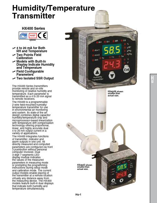
Humidity/Temperature TransmitterHu-1U 4 to 20 mA for Both RH and Temperature U T wo Points Field Calibration U M odels with Built-InDisplay Indicate Humidity and Temperature UF ield Configurable Parameters U Two Isolated SSR OutputHX400 SeriesThe HX400 Series transmitters provide remote and on‑sitemonitoring of relative humidity and temperature. Each parameter is transmitted as a 4 to 20 mA signal to remote receivers.The HX400 is a programmable 2‑wire field‑mounted humidity/temperature transmitter for use in environmental air monitoring and system. Its state‑of the art design combines digital capacitor humidity/temperature chip andmicroprocessor‑based linearization with temperature drift compensation technology offering proportional, linear, and highly accurate dual 4 to 20 mA output current in a variety of applications.The HX400 integrates functions of transmitter, indicator and alarm outputs in one unit. All directly measured and computed parameters are configured via front 3 pushbutton without personal computer involved. Dual 3‑digit 7‑segments LED display module indicates the values of the measured parameters in measuring mode or prompting the programming instructions during setup mode and calibration mode. The current output models enable placing of the transmitter at a remote location virtually any distance away from the measuring device. The HX400 models feature built‑in dual displays that indicate both humidity andtemperature simultaneously.HX402W shown smaller than actual size.HX402D shown smaller thanactual size.Hu-2SpecificationsLoop Power: 12 to 32 Vdc; dual 4 to 20 mA loop current; reverse polarity protected (Vloop = 24 Vdc, Tamb = 23 ±2°C, Rload = 250 Ω)Dual Isolated Solid State Relay Output: For output #1 and output #2; 15 mA maximum, 40 Vdc maximumAccuracy and Range of Output Current: ±0.02 mA; 4 to 20 mA (both channels)Accuracy @ 23°C and Scaleable Measurement Range: Without field calibrationRelative Humidity (RH): ±2%; 0 to 100%Temperature: ±0.5°C (0.9ºF)Dew Point: ±2°C (3.6ºF)Wet Bulb Temperature: ±2°C (3.6ºF), ‑20 to 80°C (‑4 to 176ºF)Repeatability of Relative Humidity and Temperature: ±1% RH, ±0.1°C Display Resolution: 0.1% RH, 0.1°C (temperature < 100°C)Response: 10 seconds (relative humidity); 30 seconds maximum (temperature)Filtering Ability of Sensor Cap: Stainless steel wire mesh; 0.05 mm Type of Fluid: Air and neutral gases Configuration Operation:Front 3 pushbutton with dual high bright 3‑digit LED moduleWorking Temperature:Electronics Device: ‑20 to 70°C (‑4 to 158ºF)Sensing Probe: ‑40 to 100°C (‑40 to 212ºF)Dual Miniature Loop-PoweredIndicators: Dual 3‑digits LED (green for humidity; red for temperature)Reading Rate: 1 update per secondDisplay AccuracyRelative Humidity: ±2% RH Temperature: ±0.5°C (1°F)Display Resolution:Relative Humidity: 0.1% RH Temperature: 0.1°C (0.2°F)Housing Material: POM(sensing probe); polycarbonate (electronics device)Protection: NEMA 4 (IP65) (electronic device); IP40 (sensing probe)Dimensions: 110 W x 80 L x 56 mm D (4.3 x 3.2 x 2.2")Weight: 250 g (8.8 oz)Probe Dimensions:Wall Mount Unit: L = 73 mm (2.87"), D = 15.5 mm (0.61")Remote Mount Unit: L = 100 mm (3.94"), D = 15.5 mm (0.61"), 100 cm (39.4") cable, 5.3 (0.21") diameter cableDuct Mount Unit: L = 200 mm (7.87"), D = 15.5 mm (0.61")RHCN-7000 U B right Green 3-Digit LED Display U 0 to 1 or 0 to 3 Vdc, 4 to 20 mA Inputs U 8 Amp Relay Output U S imple On/Off Control U C ompatible with RH Transmitters U O ptional RH ProbeRHCN-7001。
Modbus通讯协议说明

PLAL(dLAL) 负偏差报警限值
dF
报警回差
oPAd(CtrL) PID 控制方式
P
速率参数
I(M5)
保持参数
dt(t)
滞后时间参数
t(ctL)
控制周期
Sn
输入规格
dIP
小数点位置
dIL
输入下限显示值
dIH
输入上限显示值
SC
输入平移修正值
Ot(op1)
控制输出方式
oL(opL)
控制输出下限值
通讯地址 00H 1AH 01H 02H 03H 04H 05H 06H 07H 08H 09H 0AH 0BH 0CH
位用于曲线的 Stop/Run/Hold 控制
运行状态
Stop
Hold
Run
数据位数
2
1
1
0
3
1
0
0
2、04 指令参数地址
地址
00H
01H
02H
03H
04H
05H
06H
含义 PV 测量值 报警状态 STS
/
设定值 SV
Sn
当前段已
dIP
运行时间
上表中 STS 表示仪表的报警状态。将返回数据的低字节转换为二进制的格式,每位的数字为 0 表示报
警不存在,为 1 表示报警成立。
7
6
5
4
3
2
1
0
0
0
0
0
0
0
LoAL 报警 HIAL 报警
—7—
XMT
1、03 指令参数地址
参数名
含义
AL1
第一报警限值
AL2
养猪场智能化自动监控系统方案

养猪场养殖综合监控系统工程方案书北京盛世宏博科技有限公司养猪场养殖综合监控系统方案一、概述:随着社会的发展,经济的繁荣,现代化科学技术得到越来越广泛的应用。
北京盛世宏博科技有限公司运用现代化科学技术手段,将多场合所需参数综合起来,将功能实用、推出了适于机房、变电所、农业大棚、畜牧养殖厂、锅炉房、档案馆、医院、药厂等监测综合方案,以实现对温度、湿度、氨气、硫化氢、压力、流量、环境,烟雾报警、漏水报警等保证安全的综合监测监控系统。
二、养猪场养殖综合监控系统集中监控系统功能介绍:该系统通过现场传感器可实现各个猪舍的温度、湿度、照度等参数的自动采集监测并将事实监测数据传到监控中心监控电脑,进行实时数据显示报警,数据存储查询等功能。
现场传感器与传感器之间,现场传感器和监控中心电脑之间通过工业485总线传输。
监控室工控机可以进行数据存储、报表打印、控制输出,报警监控等分析工作。
监控软件采用工业组态监控软件开发。
软件操作简单易学,可加上现场电子地图,各方位参数、状态可在地图界面上直观明了的体现。
系统能实现所有猪舍的室内外环境温湿度,猪舍内光照强度、二氧化碳浓度、氨气浓度、猪舍内饮用水温度、大气压力,的集中监控数据采集,存储,生成数据报表,历史曲线,中央监控室统一远程监控功能。
智能监测软件应实现以下功能(1)提供实时供每个监测点的温湿度、氨气、二氧化碳浓度、光照度、大气压力;(2)提供历史数据查询,支持过去任一时段的数据查询,对一些突发事件提供数据依据。
(3)提供历史曲查看,通过对过去某一时段的变化趋势观察,可以总结出相应的变化规律,从中可以总结出一些宝贵经验。
(4)提供实时报警功能,当监测到的任一个参数达到报警条件时,监测软件会提供声音和相应数值闪烁报警,为相关管理人员提供报警提示。
(5)数据自动储,支持以Excel格式存储,可长期保存,方便日后查找和参考。
(6)监测软件采用工业组态平台,具有性能稳定、扩展方便、便于维修。
ModBus通讯模块使用说明书

LED1 LED1 LED1 LED1 LED1 电源 RS-232 地址拨盘
B A
激光传感器
+- TGR
ModBus板 转接板
RS-232
压力传感器
图三 3.1.2
ModBus 通讯模块安装于 GR-1000 或 WPCS-EXII 示意图 ModBus 通讯模块设置
连接 GR-1000 或 WPCS-EXII 颗粒物分析仪时需要设置 ModBus
7
通道数 通道1 通道2 通道3 通道4 通道5 通道6 通道7 通道8
寄存器数据类型 2μm以上颗粒数值1 2μm以上颗粒数值2 3μm以上颗粒数值1 3μm以上颗粒数值2 5μm以上颗粒数值1 5μm以上颗粒数值2 7μm以上颗粒数值1 7μm以上颗粒数值2 10μm以上颗粒数值1 10μm以上颗粒数值2 15μm以上颗粒数值1 15μm以上颗粒数值2 20μm以上颗粒数值1 20μm以上颗粒数值2 25μm以上颗粒数值1 25μm以上颗粒数值2 流量值 XDU1 XDU2
注 1:XDU1(寄存器 18)和 XDU2(寄存器 19)寄存器为系统保留。
4.1.2
寄存器换算公式
第 17 个寄存器存储的是流量值, 其流量为第 17 寄存器除以 10 的数值,有公式如下:
Flow Re g17 / 10
其中 : Flow : 流量(单位:ml/min)
Re g17 :
第 17 寄存器数据。
D100 D102 D103 D104 D101 1 2 3 J102 B A
ModBus输出
J200
J201
ModBus板
ON 12345678
+12V GND
TXD GND RXD
LT-CG-S T-005-A0021-12-V1.2空气温湿度二合一变送器产品使用手册说明书

1空气温度、湿度二合一变送器产品使用手册1概述LT-CG-S/T-005-A0021-12-V1.2空气温湿度传感器探头选用专用MEMS 芯片,并由单片机线性化调理,产品测量精度高,互换性好,免标定。
作为现场采集从站,按照标准MODBUS-RTU 通信协议RS485数字信号输出,适合远距离组网传输。
可选配液晶屏现场显示测量数据,还可选配1路继电器报警输出。
完全兼容组态王等多种上位机组态软件,易与第三方设备配套。
可广泛用于农业大棚、智能养殖、智能家居、智能交通、工厂商厦等物联网环境监测领域。
2外形规格3产品技术指标2规格型号:LT-CG-S/T-005-A0021-12-V1.2(包含液晶屏)LT-CG-S/T-005-A0020-12-V1.2(不含液晶屏)LT-CG-S/T-005-A0021-DO-12-V1.2(包含液晶屏、1路报警)空气温度测量范围:-40~80度空气温度测量精度:±0.5度空气温度分辨率:0.1度空气温度重复性:±0.2度空气温度漂移:<±0.1度/年空气湿度测量范围:0~100RH%空气湿度测量精度:±3RH%空气湿度分辨率:0.1%RH空气湿度重复性:±1%RH空气湿度漂移:<±0.5%RH/年工作环境:-20~55度,0~95%RH存储环境:-25~60度供电电压:DC7~24V最大功耗:400mW显示方式:LCD液晶屏(选项)液晶屏规格:08022行显示,每行8个字符报警(控制)输出(选配):1路继电器,触点容量(阻性):3A/AC220V、DC24V通信接口:RS485通信速率:2400、4800、9600、19200、38400、115200。
默认9600bps.通信协议:MODBUS-RTU数据格式:1、8、1、9600、N(1位起始位、8位数据位、1位停止位、无校验、9600bps波特率)终端类别:从站节点地址:001~255节点数量:31传输距离:500米(RS485通信专用电缆)变送器出厂前经过三防处理,确保高温高湿特殊环境下长期使用。
(宏物联)H-THRJ45网口温湿度传感器通讯协议说明书

6、 网络采样定时
温湿度传感器中,上位机读取数据每次间隔时间不小于 500ms,推荐值 1s。
1.1 引言..................................................................................................................... 2 1. 2 电气特点及符合标准.........................................................................................2 2、MODBUS RTU 通信协议详述..........................................................................................2 2.1 协议基本规则.....................................................................................................2 2.2 信息帧结构描述..................................................................................................2 3、 字节格式..................................................................................................................... 2 4、命令报文格式............................................................................................................... 2 4. 1 读数据:..............................................................................................................3 5、HT11S 内部报文信息....................................................................................................3 6、 网络采样定时.............................................................................................................3 7、命令举例....................................................................................................................... 3
网络温湿度变送器通讯协议 说明书

1..符合MODBUS 标准(16进制方式)。
主机查询,变送器应答的主从方式查询温湿度数据地址 03 00 00 00 02 CRCH CRCL例:对地址位为01的变送器读温湿度操作为:010*********C40B应答地址 03 04 温度H 温度L 湿度H 湿度L CRCH CRC L注:CRCH为CRC校验高字节,CRCL为CRC校验低字节。
2. 数据H(高位字节)和数据L(低位字节)为各自对应的当前温湿度值:上传数据需除十,如湿度上传16进制 0311,对应十进制00785,表示78.5%。
零下温度换算,如温度上传16进制 FF8C, 对十制为(0XFFFF-0XFF8C=0X73)115,表示-11.5℃。
3.节格式8位数据位,无校验,1位停止位,波特率1200,2400,4800,9600可以设定。
例:如对地址位01(对应变送器7位拨码开关为0000001)的变送器直接查询,在串口调试程序中进行如上通讯设置后输入:010*********C40B 即可4.和波特率的设定方法(打开产品的外壳,有两组设定参数的拨码开关)4.1波特率:出厂缺省:9600 bit/sOFF(0)Bit2 Bit1 波特率1 1 96000 1 48001 0 24000 0 12004.2地址(缺省:01)…………………………………………….…………………………………………….…………………………………………….1 1 1 1 1 0 0 1241 1 1 1 1 0 1 1251 1 1 1 1 1 0 1261 1 1 1 1 1 1 1275.CRC校验的算法下面是CRC算法的C语言的程序,用户编程可以直接应用或进行相应的移植. //本程序为网络型温湿度校验方式的示范程序,适当更改就可使用;#define CRC_CONSTANT 0xa001unsigned int crc_result=0;void crc_check (unsigned char crc_data) // crc_data is the nummber of check{bit xor_flag=1;unsigned char m;unsigned int crc_num;crc_result^=crc_data;crc_num=crc_result;crc_num&=0x0001;for (m=0;m<8;m++){if (crc_num) xor_flag=1;else xor_flag=0;crc_result>>=1;if (xor_flag) crc_result^=CRC_CONSTANT;crc_num=crc_result;crc_num&=0x0001;}}//应用示例main(){unsigned char i,j,k;unsigned char r_buffer[10];////定义发送数据数组unsigned int int_crc;r_buffer[0]=0x01;//////请求应答的变送器地址r_buffer[1]=0x03;///功能码,固定r_buffer[2]=0x00;///固定r_buffer[3]=0x00;//固定r_buffer[4]=0x00;//固定r_buffer[5]=0x02;//固定r_buffer[6]=0xc4;////crc 高r_buffer[7]=0x0b;////crc 低crc_result=0xffff;for (i=0;i<6;i++){j=r_buffer[i];crc_check (j);}int_crc=crc_result; // 01 03 00 00 00 02 CRC的高位C4,低位OB ;和int_crc高低位相反 int_crc=0;}。
SM1010B 温湿度采集模块 工具软件 说明书

SM1010B搜博MODBUS温度采集模块工具软说明书一、测温湿度原理 (3)二、软件安装 (3)三、软件基本功能 (6)3.1通讯端口及波特率设置。
(6)3.2 MODBUS设置 (7)3.3数据查询操作 (7)3.4 运行状态指示 (8)3.5 设备地址查询与修改。
(8)3.6显示修正值 (8)3.6.1 温度误差校正值 (9)3.6.2 湿度误差校正值 (9)3.7 二次开发命令观察窗口 (9)四、软件适用范围 (9)一、测温湿度原理如图1.1所示,一个单通道温湿度采集模块通过RS485转换器与电脑相连,模块通过传感器总线传感器相连,通过软件就可以读出其温湿度的值。
图1.1测温湿度原理示意图基于上述测温原理,与我们SM系列温度采集模块配套,我们开发了《搜博MODBUS温度采集模块工具软件》,以方便用户学习和掌握搜博产品,并快速应用于实际需求中。
二、软件安装软件安程过程以下面描述为例,实际文字或软件内容部分根据软件版本有所不同。
图2.1 软件安装图标找到“SM1010B搜博温湿度传感器工具软件V11.11.12”文件名,双击并按以下说明进行安装操作。
图2.2 软件安装过程直接点下一步。
图2.3软件安装选择安装路径选择合适的安装路径,也可以直接选择默认路径,还可更改到其它目录进行安装。
图2.4软件安装过程显示选定的安装目标直接点击“安装”。
图2.5 安全卫士360木马防护墙提示若弹出以上木马提示,可以选择“允许本次操作”,本软件绝无木马,请放心安装,让360放行。
若多次提示,可以先关掉防火墙后再进行安装操作。
一直点击【下一步】即可完成安装。
成功安装后,点击桌面快捷键即可运行软件。
三、软件基本功能本软件是配合搜博单通道温度采集模块使用的工具软件。
在操作本软件之前,请先将模块、传感器、通讯线连接好。
图3.1 软件界面如上图所示,软件有串口设置、观察窗、运行状态、MODBUS设置、数据查询操作、设备ID修改操作、显示修正值、二次开发命令观察窗口等几部分功能。
制药厂专用温湿度传感器ppt课件

技术指标
测量范围: 温度:-40~120℃ 湿度:0~100%RH 误差:见选型表 P精度 选项 输出信号:4~20mA 0~10V RS485 以太网输出可选
北京铁强科技发展有限公司
STH系列温湿度变送器选用数, 精 度高,长期稳定性好等特点,广泛应 用于暖通空调、电信基站、机房、 仓库、纺织、粮食储备、烟草等 要求温湿度监测的场合。
主要特性
温湿一体传感器结构,水浸可自恢复
产品结构设计合理,体积小巧,安装方便 电流,电压,RS485通讯多种输出可选
负载电阻:电流型≤500Ω 电压型≥10kΩ
供电电源:18~30V DC 功率:≤1W
后面内容直接删除就行 资料可以编辑修改使用 资料可以编辑修改使用 资料仅供参考,实际情况实际分析
主要经营:课件设计,文档制作,网络软件设计、 图文设计制作、发布广告等 秉着以优质的服务对待每一位客户,做到让客户满 意! 致力于数据挖掘,合同简历、论文写作、PPT设计、 计划书、策划案、学习课件、各类模板等方方面面, 打造全网一站式需求
MODbuS 微型红外温度传感系统说明书
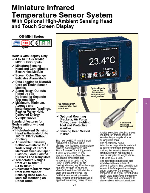
JModels with Display Only U 4 to 20 mA or RS485 MODbuS ®Outputs U M iniature SensingHead and Configurable Electronics Module U S creen Color Change Indicates Alarm Mode U D ata Logging to MicroSD Card on Touch Screen Models U A larm Relay, Outputs Rated 24 Vdc—No Need for Separate Trip Amplifier U M aximum, Minimum, Average andInstantaneous Readings, Peak or Valley Hold, Reflected Energy CompensationStandard Features for Models with or without Display U H igh-Ambient Sensing Head Withstands up to 180°C (356°F) Without Cooling U A djustable Emissivity Setting— Suitable for a Wide Range of Target Materials Such as Paper, Plastics, Food, Painted Surfaces and Many More U T emperature Ranges from -20 to 1000°C (-4 to 1832°F)U R esistant to Interference from Movement of Sensing Head Cable—Ideal for Mounting on Robot ArmsMiniature InfraredTemperature Sensor SystemWith Optional High-Ambient Sensing Head and Touch Screen Displayto IP65OS-MINI SeriesThe new Omega ® mini infrared pyrometer is packed full ofexciting new features. Its miniature sensing head measures just 18 x 45 mm (0.71 x 1.8"), making it ideal for mounting in tight spaces. a high ambient version is capable of withstanding temperatures of up to 180°C (356°F) without water or air-cooling, allowing significant energy and cost savings to be made. manufactured from 316 stainless steel and sealed to IP65, the Omega mini sensing head is ideal for food and pharmaceutical applications among many others.a wide selection of optics allows the Omega mini to focus on small or large targets at short or long distances.The special low-noiseinterconnecting cable is resistant to interference from movement, making the sensing head ideal for mounting on robot arms. It can be supplied in lengths from 1 to 30 m (3.3 x 98').The electronics module is also available with a number ofdifferent options: The backlit touch screen interface provides a large, bright display of the measured temperature in digital format and a graph view that shows the history of the measured temperature. It also enables full configuration ofOS-MINI302-D-MA shown smaller than actual size.Comes with miniature sensing head.Optional touch screen for temperature indication and configuration.the sensor including temperature range setting between-20 to 1000°C (-4 to 1832°F), adjustable filtering, peak or valley hold processing, emissivity setting and reflected energy compensation. In alarm conditions, the whole display changes color to provide an immediate and obvious alarm indication. alarm modes and levels can be configured via the touch screen. When fitted with a microsd card, the Omega minialso functions as a data logger,providing a useful means ofrecording process temperaturesfor quality assurance andtraceability. The user can selectthe sample rate and the numberof samples to be taken andschedule the data logging tostart at a certain time. With a2 gb card, the user can store28.4 million time and datestamped readings, which providesalmost 1 year’s worth of data atthe fastest possible sample rateof 1 per second.Output options include 4 to20 ma, Rs485 mOdbus andalarm relays, which are rated24 Vdc so there is no need fora separate trip amplifier. Otheroptions include mounting brackets,an air purge collar, protective lenscover and laser sighting tool.24 Vdc100 mA -CB and -CRT models 24 Vdc 100 mA-BB and -BT modelsConnectionsSpecificationsMaximum Temperature Span(Touch Screen Models): 1020°C (1868°F)Minimum Temperature Span (Touch Screen Models): 100°C (212°F)Output: 4 to 20 ma or Rs485 mOdbusAccuracy:is greaterRepeatability: ± 0.5°C or 0.5%, whichever is greaterEmissivity Setting Range: 0.20 to 1.00Emissivity Setting Method:MA Models: in electronics boxMODbuS Display Models: Via Rs485; via touch screenResponse Time, t90: 240 ms (90% response)Spectral Range: 8 to 14 μmSupply Voltage: 24 Vdc ± 5%Maximum Current Draw: 100 ma Maximum Loop Impedance(MA and MA-R-D Models): 900 Ω (4 to 20 ma output)Models):alarm relays rated 24 Vdc, 1 a,isolated 500 VdcCable Length (Sensing Head to Electronics Module): 1 m (3.3') (standard), up to 30 m (98.4')(optional)Ambient Temperature (Sensing MA and MA-R-D C4 and C4-R-DModels with Touch Screen DisplayModels with RS485/MODbuS OutputJModels with No DisplaySD card adaptor.* To order, specify model number, temperature range, output and interface, for an additional cost.** Insert cable length in meters. Extended cable is added to standard cable length, add suffix to model number, for an additional cost.Ordering Examples: OS-MINI152-D-MA, miniature infrared temperature sensor with 15:1 optics, touch screen and configurable temperature range from -20 to 1000°C (-4 to 1832°F).OS-MINI302-MA-XT, miniature infrared temperature sensor with 30:1 optics, 4 to 20 mA output and fix range from 0 to 1000°C (32 to 1832°F).OS-MINI-HA201-D-C4, miniature infrared temperature sensor with high ambient sensing head and 20:1 optics, RS485 MODBuS, relay and touch screen. OCW-3, OMEGACARE extends standard 2-year warranty to a total of 5-year warranty.OS-MINI152-MA-MT-MINI-PMCE-(3), miniature infrared temperature sensor with 15:1 optics, 4 to 20 mA output, 0 to 250°C (32 to 482°F) rangeand 3 m (10') of extension cable.Options and Accessories K Type High Ambient Sensing HeadAir purge collar.Laser sighting tool.Measurement Temperature Range Specify temperature range from table below.。
壁挂式温湿度变送器

壁挂式温湿度变送器(4-20MA、RS485通用手册)产品示意图 (1)产品特点 (2)使用范围: (2)产品技术规格 (2)安装尺寸/方式( (3)设备规范通讯协议 (3)常见问题及解决办法 (4)设备无法连接到PLC或电脑\可能的原因: (4)产品示意图产品特点1、采用原装进口电容式温湿度一体传感器2、专用的原装进口传感器处理芯片,AD转换芯片3、精心电路设计,全量程测量值标定,电流输出非线性误差只有1/10004、稳定时间短:大约1分钟;5、墙面固定安装式、结构设计简便,舒适,使维护更简单;使用范围:室内家居、暖通空调、楼宇自控系统、档案室、生产车间、仓库、药房、烟草厂、机房、大中型公共场所,智能建筑等测量的场所。
产品技术规格型号AS56-K24(原:AS-HT10I)电源12-24VDC功率0.12W /平均检测参数及探测元件瑞士温湿度一体传感器探测参数温度,湿度检测范围-40...60℃,0...100%RH 或 -20...80℃,0...100%RH检测精度(常规)±3%RH(30%RH~85%RH),±5%RH(其他湿度范围)±0.5℃(5℃~50℃)检测精度(一般)±3%RH、±0.4℃高精度±2%RH、±0.3℃相对误差≦2%预热时间1分钟稳定性使用周期内小于2%反应时间小于3分钟通讯接口Modbus 485(AS56-K24)/4-20ma(AS56-K2I)可选通讯速率9600(默认),14400,19200,28800 bps(可设),15KV防静电保护,3位独立地址,最大网络节点数64(可选)工作温度-40 ~ 80℃标定温度20℃工作湿度0-98%RH灵敏度衰减≤1%/年使用寿命≥4年外形尺寸90×84×35防护等级IP20外壳材质ABS安装尺寸/方式(壁挂式/固定式,尺寸单位:mm)端子编号功能描述备注1 B (485+)2 A (485-)3 +24V 电源正4 GND 电源负公共地5 V-H 湿度电流输出线性输出6 V-T 温度电流输出设备规范及通讯协议1、电源线耐压32V,信号线耐压72V,请不要超压使用!2、使用环境应无导电尘埃和无腐蚀金属和破坏绝缘的气体存在,避免直接光照和雨淋。
温湿度气压一体化传感器使用说明书
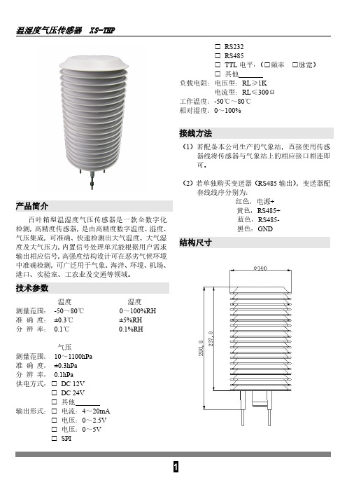
产品简介
百叶箱型温湿度气压传感器是一款全数字化 检测,高精度传感器,是由高精度数字温度、湿度、 气压集成,可准确、快速检测出大气温度、大气湿 度及大气压力,内置信号处理单元能根据用户需求 输出相应信号,高强度结构设计可在恶劣气候环境 中准确检测,可广泛用于气象、海洋、环境、机场、 港口、实验室、工农业及交通等领域。
□ DC 24V □ 其他
输出形式:□ 电流:4~20mA □ 电压:0~2.5V □ 电压:0~5V □ SPI
1
温湿度气压传感器 XS-THP
MODBUS-RTU 通讯协议
一、串口格式
数ห้องสมุดไป่ตู้位 8 位 停止位 1 或 2 位 校验位 无
波特率 9600 两次通信间隔至少 1000ms 以上 二、通讯格式
2
温湿度气压传感器 XS-THP
器件或导线; 4、传感器属于精密器件,用户在使用时请不要自
行拆卸、用尖锐物品或腐蚀性液体接触传感器 表面,以免损坏产品; 5、请保存好检定证书和合格证,维修时随同产品 一同返回。
故障排除
1、检测输出时,显示仪表示值为 0 或不在量程以 内。检查是否有外物遮挡,可能因接线问题导 致采集仪无法正确获取信息。请检查接线是否 正确、牢固;
(2)若单独购买变送器(RS485 输出),变送器配 套线线序分别为: 红色:电源+ 黄色:RS485+ 蓝色:RS485黑色:GND
结构尺寸
技术参数
温度
测量范围: -50~80℃ 准 确 度: ±0.3℃ 分 辨 率: 0.1℃
湿度
0~100%RH ±5%RH 0.1%RH
气压
测量范围: 10~1100hPa 准 确 度: ±0.3hPa 分 辨 率: 0.1hPa 供电方式:□ DC 12V
温度说明书北京昆仑海岸
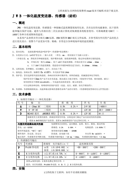
J W B 一体化温度变送器、传感器(说明)一、概述JWB一体化温度变送器、传感器是一种接触式温度测量现场用仪表,具有良好的电磁兼容、抗干扰性能和输出保护功能,通常与其相应的二次仪表或计算机采集测量系统配套使用,可准确测量-200℃~1600℃各种介质或物体的温度。
本系列产品参照并符合相关GB标准、JJG规程和IEC相关文件标准,并参考国内外同类产品的优点进行优化设计,使整个产品更加可靠、精确,非常适合各种现场环境的温度测量。
二、基本结构1、基本结构:连接装置+接线盒+保护管+(传感器+变送模块)2、长度表示方式:L=保护管总长 / 插入长度(单位:mm ,密封面以下为插入长度)。
(冷端长度:a. 降低传导和辐射温度,保护模块电路、接线端和线缆;稳定热电偶参比端的温场。
b. 冷端长度一般为150mm ;低于120℃的温度测量,冷端长度可以100mm 、50mm 。
c. 大于250℃的温度测量,看温度对冷端影响情况适当加长,如250mm 、300mm。
)3、过程连接:各种螺纹、活动螺纹、法兰、活动法兰等。
4、接线盒:防喷水型、隔爆型Ex dⅡBT4,外壳防护等级IP655、保护管:管径选择要考虑结构强度、热响应时间和可维护性;材料的耐温、机械强度和化学特性。
保护管直径≤8mm的产品不宜在有流速、搅动或压力场合使用;(铠装型可弯曲,相对耐震、耐压)常用材料有不锈钢lCr18Ni9Ti ;中高温用高铝质瓷管、钢玉质瓷管。
可以定购各种结构、特殊材料的保护套管(高温、高压、耐磨、防化学腐蚀等)。
6、传感器:传感器属损耗品,高温和振动影响传感器寿命和产品的可靠性。
(传感器铠装型相对比元件型抗震)三、技术参数1、标准信号输出(一体化变送器)应用事项:1、振动、高流速、高温环境,应加强结构或改变安装方法。
2、压力环境要按相关要求试验后使用。
3、插入长度要能到达所测量的温度场中心位置(应不小于其保护管外径的8-10倍,特殊产品例外 )。
- 1、下载文档前请自行甄别文档内容的完整性,平台不提供额外的编辑、内容补充、找答案等附加服务。
- 2、"仅部分预览"的文档,不可在线预览部分如存在完整性等问题,可反馈申请退款(可完整预览的文档不适用该条件!)。
- 3、如文档侵犯您的权益,请联系客服反馈,我们会尽快为您处理(人工客服工作时间:9:00-18:30)。
HB—RS485型温湿度变送器系列使用说明书标准modbus通讯协议使用说明书
(北京盛世宏博科技有限公司)
一、温湿度传感器:
采用高精度进口传感器,性能稳定可靠,抗干扰能力强。
二技术参数
三接线图
四通信协议说明
我们的温湿度变送器采用MODBUS规约,原因是该规约文本容易得到,协议本身也非常的简单。
而且该规约是一个开放的,有着许多国内厂商和国际厂商的支持。
MODBUS规约是MODICOM公司开发的,版权归其所有。
我们的接口采用RS485接口,比RS232具有更高的通信速率和更远的通信距离。
根据我们设备的情况,我们仅仅实现了MODBUS的一个小型子集,没有完全实现其所有内容,已经能够满足我们所有的需要。
4.1通信协议介绍
通讯默认9600波特率,1个起始位,8个数据位,无校验位,1位停止位。
本机采用部分的MODBUS协议,使用了03和06两个命令。
可读取内部的2个寄存器变量(命令03),可写入(设置)7个寄存器变量(命令06)。
有如下寄存器地址:
40001地址是温度数据,小数点后1位,271(十进制数)表示27.1度,无符号整型数40002地址是湿度数据,小数点后1位,534(十进制数)表示53.4
50001是温度下限地址,十进制数0,表示0度
50002是温度上限地址,十进制数100,表示100度
50003是湿度下限地址,十进制数1,表示1%RH
50004是湿度上限地址,十进制数100,表示100%RH
50005是设备通讯地址,十进制数3,表示3地址,范围1-255
50006是温度系数地址,小数点后1位,
50007是湿度系数地址,小数点后1位,
下面说下温度和湿度系数设置方法,点击软件的06命令,会弹出一个对话框,在输入值里面输入12表示实际温度加1.2度或1.2湿度,如果输入-13表示减去相应的值,这里面保留小数点后1位的,如输入126,单片机实际解析为12.6度,湿度系数跟此相同
4.2读取命令帧格式为(假设本机地址为1,数据均为16进制):
例子:01 03 9C 41 00 02 BA 4F
解释:
01:从机地址
03:读寄存器命令
9C 41:第一个寄存器地址
00 02:读取寄存器个数
BA 4F:CRC校验码
4.3写入命令帧格式(假设本机地址为1,数据均为16进制):
例子:01 06 C3 55 00 03 E5 9F
01:从机地址
06:写寄存器命令
C3 55:寄存器地址(例子寄存器地址是)
00 03:写入该寄存器的值
E5 9F:CRC校验码
4.4用MODBUS调试助手读取温湿度数据介绍
首先打开调试软件,然后点击
Connect选项,弹出如图界面安装图片设置完点击OK按钮,
然后Display菜单并按照图片勾选,
然后点击Setup菜单选择Poll Definition项弹出如图对话框,
该对话框用来软件自动读取40001寄存器开始,长度2个寄存器的数据,就是温湿度数据。
4.5用MODBUS调试助手写入寄存器参数介绍
首先打开调试软件,然后点击
Connect选项,弹出如图界面安装图片设置完点击OK按钮,
然后Display菜单并按照图片勾选,
然后点击Setup菜单选择Poll Definition项弹出如图对话框,
把Enable Polling勾选取消掉,因为把它勾选后软件自动每个1秒读取寄存器数据,咱们目的是写入寄存器,不是读,所有把它取消掉。
然后点击06快捷菜单
会弹出如下对话框
Slave是产品地址,Address是要写入的寄存器地址,举例为50005寄存器,Value是要写入的数据举例写入3,填好后点击Send按钮,该举例是设置板子通讯地址。
