TP TW TO说明书CN_20090921
TP-Link Deco M3W 用户手册说明书
ContentsAbout This Guide (1)Appearance (2)Set Up Y our Deco Extender (3)Dashboard (5)Update Deco Units (6)Authentication (7)About This GuideThis guide provides a brief introduction to Deco Whole Home Mesh Wi-Fi Extender and the Deco app, as well as regulatory information.Please note that features of Deco Extenders may vary slightly depending on the model and software version you have, and on your location, language and internet service provider. All images, parameters and descriptions documented in this guide are used for demonstration only.ConventionsMore Info• Specific product information can be found on the product page at https://.• A Technical Support Forum is provided for you to discuss our products at https://.• Our T echnical Support contact information can be found at the Help center of the Deco app and the Contact T echnical Support page at https:///support.Speed/Coverage/Device Quantity Disclaimer Maximum wireless transmission rates are the physical rates derived from IEEE Standard 802.11 specifications. Range, coverage, and maximum quantity of connected devices are based on test results under normal usage conditions. Actual wireless data throughput. wireless coverage, and quantity of connected devices are not guaranteed and will vary as a result of 1) environmental factors, including building materials, physical objects, and obstacles, 2) network conditions, including local interference, volume and density of traffic, product location, network complexity, and network overhead, and 3) client limitations, including rated performance, location, connection quality, and client condition.operational temperature:0-40度2Appearance Deco Extender has four LED lights and a Reset button. See the explanation below:Reset Button:Press to reset Deco Extender to factory default settings.3Set Up Y our Deco Extender Follow the steps below to add the Deco Extender to your existing Deco network.Before you start Install the Deco app and set up a Deco network. For instructions, refer to the user manual of your Deco Whole Home Mesh Wi-FiSystem/Unit. 2. Add your Deco Extender On the dashboard, tap + and select DECOS .Identify your Deco model. 3. Find a suitable spot Follow the app instructions to find a suitable spot within the range of your existing Deconetwork.44. Plug in your Deco Extender Plug the Deco Extender into a wall outlet andwait until its Power LED turns solid on. 5. Specify the location Select a location for this Deco Extender. If its location is not listed, you can create a new one by choosing Custom. 6. Finish The Deco app will automatically optimize your Deco network and finish adding the DecoExtender.View connected devices Display all Deco units Check the working status56Update Deco Units TP-Link is dedicated to improving product features and providing a better customer experience. Update Deco units when prompted in the Deco app.Update AvailableUpdating DecoUp-to-dateAuthenticationCOPYRIGHT & TRADEMARKSSpecifications are subject to change without notice. is a registered trademark of TP-Link T echnologies Co., Ltd. Other brands and product names are trademarks or registered trademarks of their respective holders.No part of the specifications may be reproduced in any form or by any means or used to make any derivative such as translation, transformation, or adaptation without permission from TP-Link T echnologies Co., Ltd. Copyright © 2018 TP-Link T echnologies Co., Ltd. All rights reserved.FCC compliance information statementProduct Name: AC1200 Whole Home Mesh Wi-Fi ExtenderModel Number: Deco M3WResponsible Party:TP-Link USA Corporation, d/b/a TP-Link North America, Inc.Address: 145 South State College Blvd. Suite 400, Brea, CA 92821Website: /us/T el: +1 626 333 0234Fax: +1 909 527 6803E-mail:*********************This equipment has been tested and found to comply with the limits for a Class B digital device, pursuant to part 15 of the FCC Rules. These limits are designed to provide reasonable protection against harmful interference in a residential installation. This equipment generates, uses and can radiate radio frequency energy and, if not installed and used in accordance with the instructions, may cause harmful interference to radio communications. However, there is no guarantee that interference will not occur in a particular installation. If this equipment does cause harmful interference to radio or television reception, which can be determined by turning the equipment off and on, the user is encouraged to try to correct the interference by one or more of the following measures:• Reorient or relocate the receiving antenna.• Increase the separation between the equipment and receiver.• Connect the equipment into an outlet on a circuit different from that to which the receiver is connected.• Consult the dealer or an experienced radio/ TV technician for help.This device complies with part 15 of the FCC Rules. Operation is subject to the following two conditions:1. This device may not cause harmful interference.2. This device must accept any interference received, including interference that may cause undesired operation.Any changes or modifications not expressly approved by the party responsible for compliance could void the user’s authority to operate the equipment.Note: The manufacturer is not responsible for any radio or TV interference caused by unauthorized modifications to this equipment. Such modifications could void the user’s authority to operate the equipment.FCC RF Radiation Exposure Statement:This equipment complies with FCC RF radiation exposure limits set forth for an uncontrolled environment. This device and its antenna must not be co-located or operating in conjunction with any other antenna or transmitter.“T o comply with FCC RF exposure compliance requirements, this grant is applicable to only Mobile Configurations. The antennas used for this transmitter must be installed to provide a separation distance of at least 20 cm from all persons and must not be co-located or operating in conjunction with any other antenna or transmitter.”This device is restricted in indoor environment only.We, TP-Link USA Corporation, has determined that the equipment shown as above has been shown to comply with the applicable technical standards, FCC part 15. There is no unauthorized change is made in the equipment and the equipment is properly maintained and operated.Issue Date: 2018-10-24CE Mark WarningThis is a class B product. In a domestic environment, this product may cause radio interference, in which case the user may be required to take adequate measures.OPERATING FREQUENCY (the maximum transmitted power)2400 MHz -2483.5 MHz (20dBm)5150 MHz -5250 MHz (23dBm)5250 MHz -5350 MHz (23dBm)5470 MHz -5725 MHz (30dBm)EU Declaration of ConformityTP-Link hereby declares that the device is in compliance with the essential requirements and other relevant provisions of directives 2014/53/EU, 2009/125/EC and 2011/65/EU.The original EU declaration of conformity may be found at /en/ceRF Exposure InformationThis device meets the EU requirements (2014/53/EU Article 3.1a) on the limitation of exposure of the general public to electromagnetic fields by way of health protection.The device complies with RF specifications when the device used at 20 cm from your body.Restricted to indoor use.Canadian Compliance StatementThis device complies with Industry Canada license-exempt RSSs. Operation is subject to the following two conditions:1. This device may not cause interference, and2. This device must accept any interference, including interference that may cause undesired operation of the device.Le présent appareil est conforme aux CNR d’Industrie Canada applicables aux appareils radio exempts de licence. L’exploitation est autorisée aux deux conditions suivantes :1. l’appareil ne doit pas produire de brouillage;2. l’utilisateur de l’appareil doit accepter tout brouillage radioélectrique subi, meme si le brouillage est susceptible d’en compromettre le fonctionnement.Caution:1. The device for operation in the band 5150–5250 MHz is only for indoor use to reduce the potential for harmful interference to co-channel mobile satellite systems;DFS (Dynamic Frequency Selection) products that operate in the bands 5250- 5350 MHz, 5470-5600MHz, and 5650-5725MHz.Avertissement:1. Le dispositif fonctionnant dans la bande 5150-5250 MHz est réservé uniquement pour une utilisation à l’intérieur afin de réduire les risques de brouillage préjudiciable aux systèmes de satellites mobiles utilisant les mêmes canaux;Les produits utilisant la technique d’atténuation DFS (sélection dynamique des fréquences) sur les bandes 5250- 5350 MHz, 5470-5600MHz et 5650-5725MHz.Radiation Exposure Statement:This equipment complies with IC radiation exposure limits set forth for an uncontrolled environment. This equipment should be installed and operatedwith minimum distance 20cm between the radiator & your body.Déclaration d’exposition aux radiations:Cet équipement est conforme aux limites d’exposition aux rayonnements IC établies pour un environnement non contr lé. Cet équipement doit être installé et utilisé avec un minimum de 20 cm de distance entre la source de rayonnement et votre corps.Industry Canada StatementCAN ICES-3 (B)/NMB-3(B)Korea Warning Statements당해 무선설비는 운용중 전파혼신 가능성이 있음.NCC Notice & BSMI Notice注意!依據 低功率電波輻射性電機管理辦法第十二條 經型式認證合格之低功率射頻電機,非經許可,公司、商號或使用者均不得擅自變更頻率、加大功率或變更原設計之特性或功能。
杭州希康维数字科技有限公司产品使用及管理指南说明书

Barrier GateUser ManualLegal Information©2022 Hangzhou Hikvision Digital Technology Co., Ltd. All rights reserved.About this ManualThe Manual includes instructions for using and managing the Product. Pictures, charts, images and all other information hereinafter are for description and explanation only. The information contained in the Manual is subject to change, without notice, due to firmware updates or other reasons. Please find the latest version of this Manual at the Hikvision website ( https:/// ).Please use this Manual with the guidance and assistance of professionals trained in supporting the Product.Trademarksand other Hikvision's trademarks and logos are the properties of Hikvision in various jurisdictions.Other trademarks and logos mentioned are the properties of their respective owners. DisclaimerTO THE MAXIMUM EXTENT PERMITTED BY APPLICABLE LAW, THIS MANUAL AND THE PRODUCT DESCRIBED, WITH ITS HARDWARE, SOFTWARE AND FIRMWARE, ARE PROVIDED "AS IS" AND "WITH ALL FAULTS AND ERRORS". HIKVISION MAKES NO WARRANTIES, EXPRESS OR IMPLIED, INCLUDING WITHOUT LIMITATION, MERCHANTABILITY, SATISFACTORY QUALITY, OR FITNESS FOR A PARTICULAR PURPOSE. THE USE OF THE PRODUCT BY YOU IS AT YOUR OWN RISK. IN NO EVENT WILL HIKVISION BE LIABLE TO YOU FOR ANY SPECIAL, CONSEQUENTIAL, INCIDENTAL, OR INDIRECT DAMAGES, INCLUDING, AMONG OTHERS, DAMAGES FOR LOSS OF BUSINESS PROFITS, BUSINESS INTERRUPTION, OR LOSS OF DATA, CORRUPTION OF SYSTEMS, OR LOSS OF DOCUMENTATION, WHETHER BASED ON BREACH OF CONTRACT, TORT (INCLUDING NEGLIGENCE), PRODUCT LIABILITY, OR OTHERWISE, IN CONNECTION WITH THE USE OF THE PRODUCT, EVEN IF HIKVISION HAS BEEN ADVISED OF THE POSSIBILITY OF SUCH DAMAGES OR LOSS.YOU ACKNOWLEDGE THAT THE NATURE OF THE INTERNET PROVIDES FOR INHERENT SECURITY RISKS, AND HIKVISION SHALL NOT TAKE ANY RESPONSIBILITIES FOR ABNORMAL OPERATION, PRIVACY LEAKAGE OR OTHER DAMAGES RESULTING FROM CYBER-ATTACK, HACKER ATTACK, VIRUS INFECTION, OR OTHER INTERNET SECURITY RISKS; HOWEVER, HIKVISION WILL PROVIDE TIMELY TECHNICAL SUPPORT IF REQUIRED.YOU AGREE TO USE THIS PRODUCT IN COMPLIANCE WITH ALL APPLICABLE LAWS, AND YOU ARE SOLELY RESPONSIBLE FOR ENSURING THAT YOUR USE CONFORMS TO THE APPLICABLE LAW. ESPECIALLY, YOU ARE RESPONSIBLE, FOR USING THIS PRODUCT IN A MANNER THAT DOES NOT INFRINGE ON THE RIGHTS OF THIRD PARTIES, INCLUDING WITHOUT LIMITATION, RIGHTS OF PUBLICITY, INTELLECTUAL PROPERTY RIGHTS, OR DATA PROTECTION AND OTHER PRIVACY RIGHTS. YOU SHALL NOT USE THIS PRODUCT FOR ANY PROHIBITED END-USES, INCLUDING THEDEVELOPMENT OR PRODUCTION OF WEAPONS OF MASS DESTRUCTION, THE DEVELOPMENT OR PRODUCTION OF CHEMICAL OR BIOLOGICAL WEAPONS, ANY ACTIVITIES IN THE CONTEXT RELATED TO ANY NUCLEAR EXPLOSIVE OR UNSAFE NUCLEAR FUEL-CYCLE, OR IN SUPPORT OF HUMAN RIGHTS ABUSES.IN THE EVENT OF ANY CONFLICTS BETWEEN THIS MANUAL AND THE APPLICABLE LAW, THE LATTER PREVAILS.Symbol Conventions The symbols that may be found in this document are defined as follows.ContentsChapter 1 Introduction (1)1.1 Product Introduction (1)1.2 Key Feature (1)Chapter 2 Installation (2)2.1 Installation Environment (2)2.2 Install Barrier Gate (2)2.2.1 Fix Barrier Gate Host (2)2.2.2 Install Boom Pole (4)2.3 Wiring (5)2.3.1 Connect to Peripheral Devices (5)2.3.2 Connect to Power Supply (7)Chapter 3 Debug (9)3.1 Remote Control (9)3.2 Button Operation (9)Chapter 4 Maintenance (13)4.1 Check Regularly (13)4.2 Check After Collision (13)4.3 Fault Code Description (13)4.4 Troubleshooting for Failed Auto Rising/Falling of Boom Pole After Power Cutoff (15)Appendix A. Peripheral Device Interfaces Introduction (16)Chapter 1 Introduction1.1 Product IntroductionBarrier gate is the entrance and exit management device to limit motor vehicle passing. It can control the boom pole automatically via parking lot management system. Or you can control the boom pole via buttons on remote controller.Barrier gate is widely applicable to toll station, parking lot, the entrance and exit of community and unit, etc. Its working temperature ranges from -30 °C to 70 °C (-22 °F to 158 °F).1.2 Key Feature●Adopts direct current brushless motor which can run steadily, applicable to entrance and exit, ETC system, etc.●The boom pole can rise rapidly and fall slowly. The barrier gate can learn the rising and falling limit positions automatically after it is powered on.●Over-voltage and over-current protection to prevent the motor from being burnt caused by locked rotor during running.●Supports anti-fall function via inductive loop, IR, etc., and protection functions including pressure wave, resistance rebound, etc.●Adjustable boom pole direction from left to right or from right to left.Chapter 2 Installation2.1 Installation EnvironmentThe installation environment of the barrier gate should meet the following requirements.●The installation space should be large enough to guarantee the boom pole can rise or fall normally.●Install the barrier gate on horizontal ground.●Installation surface requirements:○If no base is installed, the installation surface must be firm enough to fix the host to guarantee the barrier gate can run stably.○If base is needed, it is recommended to install the base with quick setting cement. The base should be horizontal. The height should be larger than 300 mm. The length and width of base should be larger than those of the actual barrier gate installation surface. Bury the set bolts prepared by yourself before installation.●If the barrier gate is anti-collision, the boom pole will flick 90° in reverse direction if it is impacted. Make sure there is no obstacle in the range.●Bury the cables before installation. The conduit should be 50 mm higher than the ground to avoid the gathered water on the ground to enter into the cable and cause short circuit.2.2 Install Barrier Gate2.2.1 Fix Barrier Gate HostFollow the steps below to fix the host of barrier gate.Steps1.Mark the positions of holes on the refuge island as shown below. The hole depth is approx. 120 mm.Figure 2-1 Mark Positions of HolesThe suggestions for positions of holes:●The holes in vertical direction should be near to the boom pole.●If the entrance/exit is unidirectional, the holes should be in the horizontal center of the refugeisland. If the entrance/exit is bi-directional, the holes in the horizontal direction should be far away from the entrance/exit.2.Punch the four M12 × 150 expansion screws in the package into the marked positions on refuge island, and fasten the nuts to make the screws expand to grip the ground. Then unfasten thenuts.Figure 2-2 Install Expansion Screws3.Uninstall the top and front covers.1)Use the L-type key to unlock the top cover.2)Lift the top cover gently and push it to take it down.3)Lift the front cover gently to take it down.Figure 2-3 Uninstall Top and Front Covers4.Fix the host.1)Put the layers on the host bottom and parallel them to the rising or falling direction of theboom pole.2)Put the host on the positions of expansion screws on the refuge island to make the screwspass through the layers. Keep the layers parallel to the rising or falling direction of the boom pole.3)Fasten the expansion nuts on the screws to fix the host.Figure 2-4 Fix HostKeep the supporting bracket of the boom pole vertically upward to avoid accident.2.2.2 Install Boom PoleFollow the steps to install boom pole.Steps1.Align the holes on the supporting bracket with those on the boom pole.2.Insert four M8 screws into the holes.3.Install flat washers, spring washers, and nuts on both sides of the screws.4.Fasten the nuts to fix the boom pole.Figure 2-5 Install Boom PoleCautionContact the professional technical personnel to change the boom pole. You may damage the barrier gate if you change it by yourself.2.3 Wiring2.3.1 Connect to Peripheral DevicesThe barrier gate can connect to peripheral devices such as entrance/exit capture unit.Steps1.Open the top cover of the host, and you can see the interfaces to connect peripheral devices.2.Connect peripheral devices to the interfaces as shown below.Refer to "Peripheral Device Interfaces Introduction" for the detailed definition of the peripheraldevices interfaces.Figure 2-7 Connect to Peripheral Devices2.3.2 Connect to Power SupplyConnect the laid power cord (RVV3 × 1.5 mm2 or above) to the power input of barrier gate. Installthe top and front covers. Use the L-type key to lock the top cover.●Cut off the power before wiring.●The power voltage of barrier gate is 220 VAC ± 10%. If the voltage exceeds the range, voltage stabilizer is needed.●Make sure the barrier gate is connected to the ground firmly, or it may cause electric shock.Figure 2-8 Power InputChapter 3 DebugAfter the installation completes, power on the barrier gate, and it will operate self-check of rising to limit position.After the self-check completes, you can control the barrier gate via remote controller or buttons.3.1 Remote ControlAfter the self-check completes, you can control the boom pole to rise, fall, and stop via the remote controller leaving factory with the barrier gate.3.2 Button OperationOpen the top cover of the host, and you can see the buttons and nixie tube. You can control the barrier gate via the buttons and judge the status via the nixie tube.There is respective initial status for the rising limit position, falling limit position, and rising speed of the barrier gate. You can adjust them via buttons if the initial status cannot meet the requirements of the installation site.Figure 3-1 Control ButtonsNote●If you need to hold the buttons to trigger operations, hold for 3 seconds or above.●The nixie tube shows the status (e.g., H0) and fault codes (hexadecimal characters, e.g., 1A). If the fault codes appear on the nixie tube, it means there is operation error. Contact the technical personnel of our company to solve the problems.Table 3-1 Button Operation DescriptionThe controller can learn no more than 481.Press2.Holdadjust the boom pole to H5 status.Displayed fallingunit of thedurationPressnixie tube displays rL.Apply control signal to let the boom pole rise to the limit position.Holdadjust the boom pole to H8 status.HoldPressChapter 4 Maintenance4.1 Check RegularlyThe barrier gate should be maintained every three months. Check according to the following instructions.●Check mechanical drive.●Check if the wiring and GND is firm.●Check if the motor sounds abnormally.4.2 Check After Collision●Check if the slewer is damaged. Change it if it is damaged.●Check if the boom pole is curved. Change it if it is curved.●Check if the barrier gate sounds abnormally during running. Contact the qualified after-sales service agent in time.4.3 Fault Code DescriptionWhen the barrier gate is abnormal, open the top cover, and observe the fault code on the nixie tube to troubleshoot.Table 4-1 Fault Code Description4.4 Troubleshooting for Failed Auto Rising/Falling of Boom Pole After Power CutoffIf the boom pole cannot rise or fall automatically after the power is cut off suddenly, follow the steps to solve the problem.Steps1.Uninstall the top and front covers.2.Insert L-type wrench into the hexagonal hole on the host.Figure 4-1 Rotate Wrench3.Rotate the wrench according to the barrier gate status.-If the barrier gate is in the falling limit status, rotate the wrench anticlockwise to raise the boom pole slowly until it can rise and fall automatically.-If the barrier gate is in the rising limit status, rotate the wrench clockwise to make the boom pole fall slowly until it can rise and fall automatically.Appendix A. Peripheral Device InterfacesIntroductionOpen the top cover of host, and you can see the interfaces as shown below.Figure A-1 Interfaces Table A-1 Interface Description。
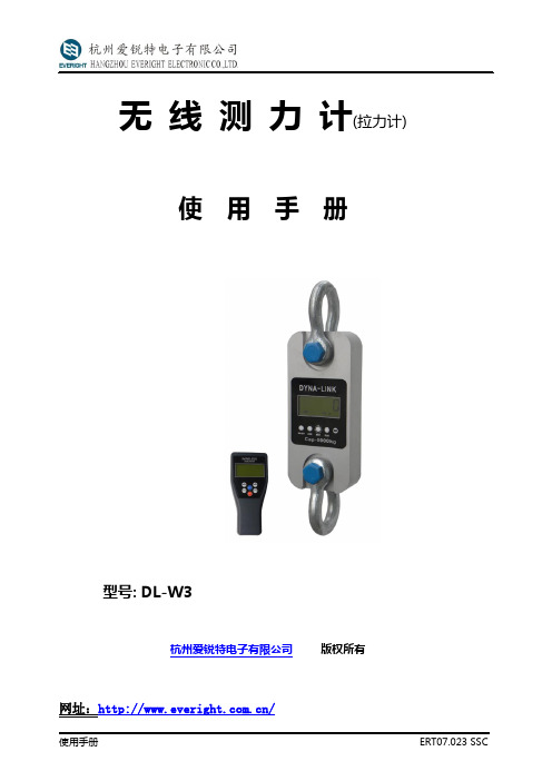
无线测力计(拉力计)使用手册(DL-W3)
无线测力计(拉力计) 使用手册型号: DL-W3杭州爱锐特电子有限公司版权所有目录安全提示 (2)一、产品规格说明 (3)1.产品特色 (3)2.主要技术指标 (3)3.产品规格 (4)4.测力计外观示意图 (4)5.电源说明 (5)二、测力计显示说明............................................................................................................. . (5)1. 液晶显示区 (5)2. 符号 (5)3. 按键说明 (6)三、仪表显示说明............................................................................................................. . (5)1. 液晶显示区 (5)2. 符号 (5)3. 按键说明 (6)四、使用功能说明 (7)1.开/关机 (7)2.置零 (7)3.去皮 (7)4.保持 (7)5.累积 (7)6查询累积 (8)7.清除累积 (8)8.电池电量检测.. (8)9.峰值保持 (8)10.零位显示 (8)11.单位转换.............................................................................................................. . (8)12. 控制点设置 (9)五、提示符功能说明 (10)六、故障判别 (11)安全提示:1. 此测力计设计时,已考虑其安全系数,但切记在使用时勿超过其最大秤量(Cap.),最大秤量已标示于测力计明显处。
若超载使用而造成的任何损害,本公司将无法负责。
2. 请定期每三个月检查吊环、吊钩及其它零件,开口销,螺丝是否有松动、变形、龟裂…等現象,如有发现任何异样,请立刻停止使用並送回经销处,维修更换零件,以确保安全。
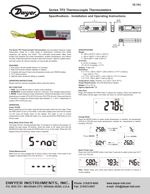
Dwyer Instruments TP2热敏电话计说明书
SPECIFICATIONSRange:K: -328 to 2372°F (-200 to 1300°C);J: -202 to 1652°F (-130 to 900°C);T: -328 to 662°F (-200 to 350°C).Accuracy:K: ±0.3% of reading + 1°C;J/T: ±0.1% of reading + 0.7°C.Display: 4 digit LCD.Resolution:K: 0.1°F/C: -328 to 1202°F (-200 to 650°C); 2°F/1°C (others);Over 1000°C 1°F/C.J: 0.1°F/C: -202 to 932°F (-130 to 500°C); 2°F/1°C (others);T: 0.1°F/C: -328 to 662°F (-200 to 350°C).Temperature Limits: Ambient -4 to 122°F (-20 to 50°C).Power Requirements: One CR-2032 lithium battery.Weight: 3.2 oz (91 g).Agency Approvals: CE.The Series TP2 Thermocouple Thermometerscan accurately measure a largetemperature range fora wide rangeof applications includingfood safetyinspection, lab testing, and HVAC. This hand-held thermometer offers threemodels that measure the probe temperature, ambient temperature, and relativehumidity. Additional features include a data hold function, high/low audible alarm,and auto power off. Device includes a K type probe and battery.FEATURES1. Auto power off with disable feature (15 minutes).2. Data hold function freezes readings on display.3. Complete with type K bead wire temperature probe and CR2032 battery.4. °C/°F select function.5. High/low alarm threshold setting is available.OPERATING INSTRUCTIONSPlease read the manual completely before using this device.KEY FUNCTION1. PWR: Turn on/off the meter or holds current readings.2. MX/MI/AVG:Cycles between minimum, maximum, and average measurement.3. MODE:Cycles between probe temperature, ambient temperature and humidity(depending on model) (TP2-20/TP2-30 only), RH (TP2-30 only). Press and hold for3 seconds to charge the thermocouple type between K, J, and T (depending onmodel) (TP2-10/TP2-20 only).OPERATIONPower On/OffBefore powering on the meter, plug the thermocouple probe into the meter. Pressthe PWR button to turn on the meter. It will make a beep sound and the full screenof LCD icons will briefly show on the display. The meter is now in normalmeasurement mode. While the meter is on, press and hold the PWR button to turnoff the meter.Sleep Mode (Auto Power Off)The meter will turn off automatically after 15 minutes if no buttons are pressed. Todisable the auto power off function, when the meter is off, press and hold theMX/MI/AVG button then press the PWR button to turn on the meter. When the LCDdisplay shows the following, sleep mode is disabled.Taking MeasurementMake sure you have plugged the K sensor probe in the meter. If the probe is notplugged in appropriately, the LCD will show “----” on the display.545/64Data HoldPress and release the PWR button to freeze the reading. Press and release thePWR button shortly again, the meter will return to normal measurement.Change ModePress the MODE button to select probe temperature or ambient, air temperature(TP2-20 & TP2-30) and probe temperature, ambient air temperature or relativehumidity (TP2-30).Select Probe TypePress and hold the MODE button more than 3 seconds to select probe type K/J/T(TP2-10 & TP2-20).Note: Please check your probe type before selecting this function to ensure acorrect reading.to normal measurement.Change UnitWhen the device is off press the MODE and PWR button at the same time to enter function. Press the MODE button to select °C or °F. Pressbutton again to save the unit.Alarm SettingStep 1. Hi Temp. Alarm SelectWhen the meter is off, press the MODE and PWR button at the same time. Pass Step 2. Hi Temp. Alarm SettingWhen Hi Temp. alarm is on, “Hi Set” icons with the default value 50°C (122°F) or the last setting will appear on the LCD. Keep pressing the MODE button to increase and release the button when you reachStep 3. Lo Temp. Alarm Select Step 4. Lo Temp. Alarm SettingPWR button to save Lo Temp. settings, and go back to normal measurement. Example 1 - Set Hi Temp. Alarm at 1283°CError MessagesNote: If above error messagesInstruments, Inc. for technical service.Step 1:Keep pressing the MODE button, the numbers willE-2E-3E-4E-5E-6Humidity sensor is failed.Temperature sensor is failed.Operation temperature is too high.Operation temperature is too low.Some hardware has failed.。
公园双塔渗透式干燥器TW、TWP和TWB系列说明书

Parker Twin Tower Desiccant DryersTWP SeriesParker TWP Series Externally Heated Desiccant Air Dryers operate similarly to the TW series to achieve a pressure dewpoint of -40°F , but the design includes a heat source to assist the purge air during regeneration. This is called Thermal Swing Adsorption and helps reduce the energy required to regenerate the desiccant bed.For over 50 years, Parker Hannifin’s Industrial Gas Filtration and Generation Division has established itself as an industry leader in the design, development and manufacture of a wide range of filtration and separation products. Designed to meet the needs of global customers through a dedicated focus on key market sectors, Parker’s products deliver a unique combination of innovation and excellence in the most demanding applications, helping our valued customers to maximize the productivity and profitability of their manufacturing and process operations. Parker’s engineering expertise and broad range of core technologies uniquely positions the company to help solve the world’s greatest engineering challenges, while delivering real and lasting value to every customer.TW SeriesParker TW Series Heatless Desiccant Air Dryers remove water vapor from compressed air through a process known as Pressure Swing Adsorption. A standard pressure dewpoint of -40°F (-40°C) is attained by directing the flow of saturated compressed air over a bed of desiccant. The desiccant bed is regenerated by using dry purge air from the system.TWB SeriesParker TWB Series Blower Purge Desiccant Air Dryers achieve a pressure dewpoint of -40°F by using Blower Regeneration technology.In this design, the dryer uses a heat source and a blower to push large volumes of ambient air across the desiccant bed during regeneration, instead of using dry purge air from the system. As a result, the TWB design is the most energy efficient of the Twin Tower dryers in Parker’s offering.EquipmentTW 1501Butterfly ValveTWP 801ControllersHeatless Basic ControllerOptional on all TW ModelsExternally Heated & Blower Purge Advanced ControllerAll TWB & TWP ModelsHeatless Advanced ControllerOptional on TW0100 & LargerPowerLoc® Energy Management System Energy savings of up to 80% can be achieved with the proven PowerLoc® energy management system. Regeneration requirements are dependent on flow, pressure and temperature. The PowerLoc® system allows the cost of drying compressed air to be matched exactlyto your plant conditions. PowerLoc®controls the drying cycle by continuously reacting to the loading under which thedryer is operating and minimizes the energy input required.As dryers rarely operate at full rated capacity all of the time (eg. during shift work and periods of low demand), this energy management system can provide considerable savings.The Advanced Controller is designed to accomodate Parker’s PowerLoc® Energy Management System. Flashes greenwhen in energy saving mode.Compressed Air Quality to ISO 8573.1:2010The Industry Standard Method for Specifying Compressed Air Cleanliness (in accordance with ISO 8573-1 2,2,2)main-exhaust valved r y i n gair outinlet valveair inexhaustp u r g i n gTWB Series Blower Purgeair inpre-exhaust valvemain-exhaust valve exhaust mufflers blowerd r y i n gh e a t e rr e g e n e r a t i n gcooldown valveair outinlet valveair ininlet valver e g e n e r a t i n gpre-exhaust valvemain-exhaust valve exhaust mufflers d r y i n gh e a t e rpurge regulatorair outTWP Externally Heated withPatented Multi-PortTypically one of four differentmethods is used for regeneration:• Pressure Swing Adsorption • Thermal Swing Adsorption • Blower Regeneration •Vacuum RegnerationThe regeneration method used by an adsorption dryer usually has a direct correlation to its purchase price.The running costs associated with an adsorption dryer are usually linked to the regeneration method.The purchasing decision for an adsorption dryer is often based upon the dryer’s running costs and the upfront purchase price.Types of RegenerationThe TW Series is the simplest desic-cant air dryer in our offering, the dryer uses heatless pressure swing adsorption for drying the compressed air to -40°F PDP . The pressure swings between a left and a right tower typically on a cycle of 5 to 10 minutes. During regeneration, a percentage of the dry compressed air is used for purge, this helps regenerate the fully adsorbed desiccant.The TWP Series adds a heater to the regeneration process, this is called heated regeneration or thermal swing adsorption. The desiccant dryer is still designed to achieve -40°F PDP , but it includes a heater to reduce the amount of purge air required during regenera-tion. The regeneration time for the TWP series is extended to 8 hours to complete a full cycle.TW SeriesThe TWB Series is the most advanced design in our desiccant dryer offering, it includes a heater and a blower for regen-eration of the desiccant bed. This process is known as blower regeneration and is the most energy efficient option available. Instead of using dry compressed air for the purge cycle, a blower pushes hot ambient air across the desiccant bed during regenera-tion. In order to cool down the desiccant bed, a small percentage of purge air is used at the end of the cycle before the towers switch.Notes• Above information should be used as a guideline. Flows are at 100 psig inlet pressure, 100°F (38°C) inlet temperature and100°F (38°C) ambient temperature. For specific applications, please consult Parker Applications Engineering.• Weight includes desiccant (shipped loose Models TW2000 and up).• Pressure relief valve variance +/- 10%.-40°F (-40°C) with Activated Alumina DesiccantCorrection FactorsTo obtain dryer capacity at new conditions, multiply nominal capacity x C1 x C2.-40°F (-40°C) with Activated Alumina DesiccantNotes• Above information should be used as a guideline. Flows are at 100 psig inlet pressure,100°F (38°C) inlet temperature and 100°F (38°C) ambient temperature. For specific applications,please consult Parker Applications Engineering.• Weight includes desiccant (shipped loose TWP2001 and up).•Pressure relief valve variance +/- 10%.Correction FactorsTo obtain dryer capacity at new conditions, multiplynominal capacity x C1 x C2.Notes• Above information should be used as a guideline. Flows are at 100 psig inlet pressure,100°F (38°C) inlet temperature and 100°F (38°C) ambient temperature. For specific applications,please consult Parker Applications Engineering.• Weight includes desiccant (shipped loose TWB2001 and up).•Pressure relief valve variance +/- 10%.TWB Product Selection-40°F (-40°C) with Activated Alumina DesiccantCorrection FactorsTo obtain dryer capacity at new conditions, multiplynominal capacity x C1 x C2.Aerospace Filtration Division Greensboro, North Carolina 336 668 4444 Bioscience & Water Filtration Division Bioscience Filtration Oxnard, California877 784 2234Water Purification Carson, California310 608 5600Engine Mobile Aftermarket Division Kearney, Nebraska308 234 1951Engine Mobile Original Equipment Division Modesto, California209 521 7860HVAC Filtration Division Jeffersonville, Indiana Industrial Gas Filtration &Generation DivisionLancaster, NY800 343 4048Industrial ProcessFiltration DivisionMineral Wells, T exas940 325 2575Bioscience EngineeringFiltration Division EMEABirtley, United Kingdom+44 (0) 191 410 5121Engine Mobile FiltrationDivision EMEADewsbury, United Kingdom+44 (0) 1924 487 037Gas Separation &Filtration Division EMEAT eam Valley, United Kingdom+44 (0) 191 402 9000Gas Turbine Filtration DivisionAustralia Filtration DivisionCastle Hill, Australia+61 2 9634 7777China Filtration DivisionShanghai, China+86 21 2067 2067India Filtration DivisionChennai, India+91 22 4391 0700Korea Filtration DivisionHwaseon City, Korea+82 31 359 0852Latin America Filtration DivisionSao Paulo, Brazil+55 12 4009 3500Parker Filtration GroupPhone 800 343 4048 /igfg。
PlatinumTools TP500商品说明书

FEATURES•Tests for shorts, opens, miswires, reversals and split pairs•Auto-on and auto-off when testing cables, just plug both ends into tester!•Automatically tests for shorts with one end plugged into the tester•Cable test results displayed on main unitand remote unit, in less than 2 seconds afterplugging in the cable•Snap-together case for easy storage andconvenient patch cable testing•Tone generator mode for use with tone tracers, auto-off•Debug mode with from/to and failures for each pair•Battery low indicatorMain Unit Results – The main unit indicates thebeginning of a test by flashing the pair lights in sequencetop to bottom. The cable is then tested and the resultsdisplayed as follows:Pair light off – Pair is open. Depending on the wiringstandard, this may be correct.Pair light on – Pair is wired correctly.Pair light is flashing – One or more errors weredetected for this pair, as indicated by flashing errorlights.If there are no flashing lights, the results are displayedfor 2 seconds.If there was an error, the results are displayed for twiceas long.If the lights for the pairs expected are on, the cable isgood.Remote Unit Results – The remote unit indicates thebeginning of a test by flashing the pair lights quickly, theorder or number of lights flashed depends on the cablebeing tested.Debug Mode – (See “Ethernet Up-Link Cable Example”)Pair connected from1-2 to 3-6 (miswire)Pair connected from3-6 to 1-2 (miswire)Pair connected from4-5 to 4-5 (good)Pair connected from7-8 to 7-8 (good)。
迈特尔托德湿度仪HX204 HS153软件版本 说明书
Moisture Analyzer HX204/HS153Software Release NotesContents1. HX204 and HS153 Software Version History ......................................................... 22. Software Product Lifecycle Policy ........................................................................... 33. Software version 3.0 and higher ............................................................................. 44. Software version 2.x and 1.x .................................................................................. 85.Support and Contact Information (13)S o f t w a r e R e l e a s e N o t e sS W R e l e a s e N o t e s1. HX204 and HS153 Software Version History1For TDNR (Type Definition Number) update, please contact your METTLER TOLEDO representative.DateTopic DescriptionTerminal Drying Unit TDNR 1 update needed June 25, 2021 Bug FixSee Information on Annex 3.31 3.31 1.60 No Jan 25, 2021 SW update & Bug fix See information on Annex 3.30 3.30 1.60 No May 25, 2020 SW update & Bug fix See information on Annex 3.20 See information on Annex 2.50 3.20 2.50 1.60 No Jan 10, 2020 SW update & bug fixSee information on Annex 3.10 See information on Annex 2.40 3.10 2.40 1.60 No Sept 19, 2019 New Hardware See information on Annex 3.00 3.00 1.50 No June 17, 2019 Bug fixSee information on Annex 2.32 2.32 1.50 No May 15, 2019 SW update & bug fix See information on Annex 2.31 2.31 1.50 No Sept 20, 2017 Bug fix See information on Annex 2.22 2.22 1.40 No Jan 26, 2017 Bug fixSee information on Annex 2.21 2.21 1.40 No Jan 23, 2017 SW update & bug fix See information on Annex 2.20 2.20 1.40 No Oct 15, 2015 Bug fix See information on Annex 2.13 2.13 1.31 No Dec 19, 2014 Bug fix See information on Annex 2.12 2.12 1.30 No Sept 30, 2014 Bug fixSee information on Annex 2.11 2.11 1.30 No July 1, 2014 SW update & bug fix See information on Annex 2.10 2.10 1.20 No Nov 22, 2013 Bug fix Relevant for production only 2.02 1.10 No Nov 07, 2013Bug fixFixes for SmartCal test display2.011.10NoNov 01, 2013 SW update & bug fix A4/Letter printouts, network connectivity, PDF reports, automatic SmartCal normalization, RHT sensor, SOC delay, AutoMet, FreeFactor. Bug Fixes.2.00 1.10 NoDec 19, 2012 SW update & bug fix MT-SICS commands, acoustic feedback, new export functions. Improved test measurement, step drying and SW upgrade process. Bug fixes.1.20 1.10 NoJuly 26, 2012 Bug fixFixes in Russian and Japanese translations 1.10 1.00 No Apr 18, 2012Initial Version HX2041.001.00NoS W R e l e a s e N o t e s2. Software Product Lifecycle PolicyThe Software versions 1.x and 2.x are supported until 20th of December 2022. This means that patches for critical bugs are guaranteed until this date, new features will not be implemented after software version 2.50.The terminals of the instruments with serial number B940371811 and lower contain a processor which only supports software version 1.x and 2.x (terminal software identification 30008642).When using a terminal with the terminal software identification 30535417, the new software version 3.xx or higher is automatically delivered, which will continue to be extended with new features.S W R e l e a s e N o t e s3. Software version 3.0 and higherA new terminal hardware including a different processor is existing in instruments starting with serial number B940371812. This new hardware is not compatible with software versions 2.xx and 1.xx and requires software version 3.0 and higher (terminal software identification 30535417).ANNEX 3.31DescriptionTerminal Software V3.31, Drying Unit Software V1.60S W R e l e a s e N o t e sDescriptionTerminal Software V3.30, Drying Unit Software V1.60S W R e l e a s e N o t e sDescriptionTerminal Software V3.20, Drying Unit Software V1.60ANNEX 3.10DescriptionTerminal Software V3.10, Drying Unit Software V1.60S W R e l e a s e N o t e sANNEX 3.00DescriptionTerminal Software V3.00, Drying Unit Software V1.50S W R e l e a s e N o t e s4. Software version 2.x and 1.xInstruments with serial number B940371811 and lower contain a processor which only supports software version 1.x and 2.x (terminal software identification 30008642) but not 3.x and higher. In case of defect, the terminal needs to be replaced which runs on software version 3.x and higher.ANNEX 2.50DescriptionTerminal Software V2.50, Drying Unit Software V1.60ANNEX 2.40DescriptionTerminal Software V2.40, Drying Unit Software V1.60ANNEX 2.32DescriptionTerminal Software V2.32, Drying Unit Software V1.50S W R e l e a s e N o t e sANNEX 2.31DescriptionTerminal Software V2.31, Drying Unit Software V1.50ANNEX 2.22DescriptionTerminal Software V2.22, Drying Unit Software V1.40S W R e l e a s e N o t e sANNEX 2.21DescriptionTerminal Software V2.21, Drying Unit Software V1.40ANNEX 2.20DescriptionTerminal Software V2.20, Drying Unit Software V1.40S W R e l e a s e N o t e sANNEX 2.13DescriptionTerminal Software V2.13, Drying Unit Software V1.31ANNEX 2.12DescriptionTerminal Software V2.12, Drying Unit Software V1.30S W R e l e a s e N o t e sANNEX 2.11DescriptionTerminal Software V2.11, Drying Unit Software V1.30ANNEX 2.10DescriptionTerminal Software V2.10, Drying Unit Software V1.20S W R e l e a s e N o t e s5. Support and Contact InformationIf you need further support or advice, please contact us: /contact。
TP-1A 简单操作说明书
TP-1A简单操作说明书仪器出厂前已经标定过,用户可按下列方法直接测定样品:1、打开电源,仪器进入预热状态。
2、分别吸取10mL蒸馏水(空白)或待测水样置于清洗干净的反应管中(注:水样中铜浓度如超过1mg/L,则分别移取蒸馏水和样品各5mL,并补水至10mL),分别加入0.5mL试剂(一),具塞摇匀,加入0.5mL试剂(二),具塞摇匀。
静置20分钟。
3、在仪器上,按箭头键选择“选择曲线”功能,利用上下箭头键选择所需的标准曲线序号,按“确认”键确认。
4、将待测的样品空白注入比色皿内,擦净外壁,放入比色槽内测定其吸光度,按“测试空白”键待吸光度值稳定后,按“确认”键,仪器自动调零。
5、倒掉比色皿中溶液,清洗后,将待测的样品注入同一比色皿内,擦净外壁,放入比色槽内按“测试样品”键,仪器显示其吸光度及样品的浓度值,仪器显示该样品总磷浓度值(mg/L),按“确认”键则该值被存储于仪器内。
注:仪器出厂已标定两条工作曲线,其中第一条测定范围为0~1mg/L,第二条曲线为1-~10mg/L,用户根据需要选择。
用户在使用过程中,如样品超过1mg/L,请取水样5mL并补水至10mL,比色时请选用第二条曲线。
仪器操作一、概述总磷包括溶解的、颗粒的、有机的和无机磷。
磷是生物生长的必需的元素之一,介水体中磷含量过高(超过0.2mg/L),可造成藻类的过度繁殖,直至数量上达到有害的程度,造成湖泊、河流透明度降低,水质变坏。
该仪器广泛适用于地表水、地面水、污水和工业废水的测定。
本仪器具有以下优点:1、利用冷光、单色光作光源,光学稳定性极佳,不会受到各种光的干扰。
2、大屏幕液晶中文显示,所有设定、标定、记录操作全部在同集成环境下实现。
3、高温消解和主机分开,避免了高温部分对光学系统的影响。
4、利用V/F转换、软件冗余、软件陷阱等技术,抗干扰性强。
5、可贮存10条工作曲线及99个历史记录,断电不丢失。
6、主机机壳采用模后ABS材料,防腐蚀性好。
TP320型电导率仪使用说明书
目录一、概述 (1)1.1仪器的外型 (1)1.2适用标准 (2)1.3主要特点及功能 (2)二、技术指标 (3)三、工作原理 (4)四、仪器的安装 (5)4.1配件检查 (5)4.2仪器的安装 (6)1、位置要求 (6)2、电极支架的安装 (6)3、电极支架的调节 (7)4、电极的安装 (7)5、开机方法 (8)五、仪器的操作 (8)5.1显示说明 (8)5.2按键说明 (9)5.3功能菜单及功能 (10)1、参数设置 (10)2、仪器日志 (14)3、维护服务 (16)4、仪器信息 (17)5、数据的存储 (18)六、仪器校准 (19)6.1电气校准 (19)6.2电导样品校准 (19)6.3校准温度 (22)七、电极的选择 (23)八、注意事项 (24)九、仪器常见故障判别与处理 (25)十、联系方法 (26)一 概 述TP320型电导率仪是我公司新一代全中文微机型高档仪器,具有全中文显示、中文菜单式操作、高智能化、多功能、测量性能高、环境适应性强等特点。
可广泛应用于火电、化工化肥、冶金、环保、制药、生化、食品和自来水等溶液电导率值的测量。
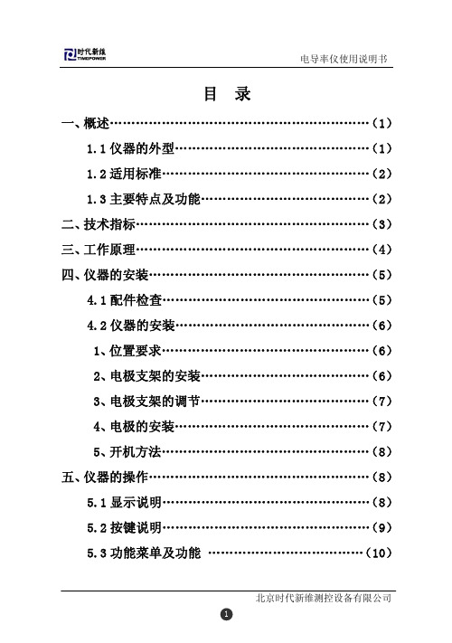
1.1仪器的外型仪器的外型如下图1-1。
图1-1TP320 型电导率仪由主机、复合电导率电极及电极支架组成。
仪器配有测量灵敏的电导率电极,仪器带有自动温度补偿功能,测量可靠、数据准确。
仪器有一个电导输入通道和一个温度输入通道,当不需要自动温度补偿时,可以手动设置进行温度补偿,当需要进行自动温度补偿时,样品的温度由一个内置的Pt1000温度电极进行测量。
1.2 适用标准引用国标GB/T 11007-2008《电导率仪试验方法》。
1.3主要特点及功能全智能化:TP320电导率仪采用高精度AD转换和单片机微处理技术,能实现电导率的测量、温度的测量、温度自动补偿、量程自动转换等多种功能。
25℃折算:对当前温度下的电导率值进行25℃折算,实现了显 示25℃时的电导率值,特别适合电厂多种水质的测量。
迪塞尔科技 TPP1000 10X Passive 探头操作指南说明书
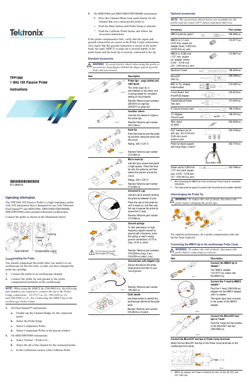
Operating informationThe TPP100010X Passive Probe is a high impedance probe with 10X attenuation that is designed for use with Tektronix FlexChannel™and MDO3000,MDO/MSO/DPO4000B,MSO/DPO5000series ground-referenced oscilloscopes.Connect the probe as shown in the illustrationsbelow.Compensating the ProbeYou should compensate the probe after you attach it to an oscilloscope for the first time,or after you have changed the probe tip cartridge.1.Connect the probe to an oscilloscope channel.2.Connect the probe tip and ground to the probe compensation terminals on the oscilloscope.NOTE.When using the MMCX tip (206-0663-xx),the following part numbers are required to connect the tip to the Probe Comp connections:131-9717-xx (1),196-3434-xx (1),and 206-0569-xx (2).See Connecting the MMCX tip to the oscilloscope Probe Comp.3.On FlexChannel™instruments:a.Double tap the Channel Badge for the connected probe.b.Select the Probe Setup.c.Select Compensate Probe.d.Select Compensate Probe in the pop up window.4.On MSO/DPO5000instruments:a.Select Vertical >Probe Cal....b.Select the tab of the channel for the connected probe.c.In the Calibration section,click Calibrate Probe.5.On MDO3000and MDO/MSO/DPO4000B instruments:Press the Channel Menu front panel button for the channel that you connected the probe to.Push the More button until Probe Setup is selected.Push the Calibrate Probe button and follow the on-screen instructions.If the probe compensation fails,verify that the signal and ground connections are secure at the Probe Comp connections.Also check that the ground connection is secure at the probe head,the rigid,MMCX or pogo tip is secured tightly in the probe head,and the hook tip is securely connected to the tip.StandardaccessoriesWARNING.To avoid electric shock when using the probe or accessories,keep fingers behind the finger guard of probe body and accessories.ItemDescriptionProbe tips –pogo (white)and rigid (gray)The white pogo tip ispre-installed on the probe,and is spring-loaded for compliant testing of circuit boards.Reorder Tektronix part numbers:206-0610-xx (rigid tip)206-0611-xx (pogotip)Insulator sleeveUnscrew this sleeve to replace the probe tips.Reorder Tektronix part number342-1194-xx Hook tipPress the hook tip onto the probe tip and then clamp the hook onto the circuit.Rating:300V CAT II Reorder Tektronix part number013-0362-xx Micro hook tipUse this tip to access test points in tight spaces.Press the hook tip onto the probe tip and then extend the pincers around the circuit.Rating:300V CAT II Reorder Tektronix part number013-0363-xx Universal IC capUse this cap to prevent shorting the probe tip between IC pins.Press the cap on the probe tip until it snaps on,and then spin the cap to expose the probe tip toward the IC lead.Reorder Tektronix part number013-0366-xx Ground springsTo limit aberrations on high frequency signals caused by ground path inductance,bend the spring to reach nearby ground connections (<0.75in,long;<0.25in,short).Reorder Tektronix part numbers:016-2028-xx (long,2ea.)016-2034-xx (short,2ea.)Ground lead,with alligator clip Secure the lead to the probe head ground and then to your circuit ground.Reorder Tektronix part number196-3521-xx Color bandsUse these bands to identify the oscilloscope channel at the probe head.Reorder Tektronix part number 016-0633-xx (5pairs)Optional accessoriesNOTE.The accessories shown below are available for the probes and are rated ≤30V unless indicated otherwise.AccessoryPart number MMCX probe tip (gold)1206-0663-xx MMCX to 0.1-inch (2.54mm)square pin adapter (blue),0.025-inch (0.635mm)sq.pins 131-9717-xxMMCX to 0.062inch (1.57mm)square pin adapter (white),0.016-0.018inch (0.4-0.46mm)sq.pins 131-9677-xxElectricalY-Lead 196-3434-xx MicroCKT TestTip206-0569-xx BNC to Tip Adapter,Unterminated 013-0367-xx Circuit Board Test Point/PCBAdapter 016-2016-xx Chassis-Mount Probe TestJack131-4210-xx 6”Clip-on GroundLead 196-3198-xx 12”Alligator GroundLead 196-3512-xx Wire,spool,32AWG020-3045-xx DUT Interface pin kit with (qty.20)0.018inch (0.46mm)round solder-inpins020-3169-xxProbe tip tripod support with living hinge,2each2352-1170-xxSolder aid for 0.062-inch (1.57mm)pitch square pins,0.016-0.018-inch (0.4-0.46mm)sq.pins003-1946-xx1See Connecting the MMCX tip to the oscilloscope Probe Comp for connection instructions.2The tripod probe tip support is pictured with the probe tip and adapter attached.Interchanging the ProbeTipWARNING.To reduce the risk of shock,disconnect the probe before changing the probetips.For optimal performance,do a probe compensation after the tip has been replaced.Connecting the MMCX tip to the oscilloscope ProbeCompWARNING.To reduce the risk of shock,disconnect the probe before connecting accessories.ItemDescriptionConnect the MMCX tip to adapter 1The MMCX adapter(131-9717-xx)snaps onto the MMCXtip.Connect the Y–lead to MMCX adapter 1Push the Y–lead (196-3434-xx)adapter into the MMCX adapter until it is seated.The signal input (red)connects to the center of the MMCXadapter.Connect the MicroCKT test tips to Y-leadPush the Y-lead into the handles of the MicroCKT test tips (206-0569-xx).Connect the MicroCKT test tips to Probe Comp terminals Attach the two MicoCKT test tips to the Probe Comp terminals on the ocsilloscope frontpanel.1MMCX tip,adapter,and Y-lead is limited to 30vrms,42Vpk,60VDC,and OVT <500Vpk.TPP10001GHz 10X Passive Probe Instructions*P071280904*071-2809-04Electrical and mechanical speci ficationsCharacteristic Speci fication Bandwidth (–3dB)1GHz System rise time (typical)<450psSystem input capacitance Rigid and MMCX tip:3.9pF ±0.3pF Pogo pin tip:5.1pF ±0.5pF System attenuation accuracy 10:1±2.2%Probe series resistance @DC 9.75M Ω±0.5%System input resistance @DC 10M Ω±2%Propagation delay ~5.67ns Maximum input voltage 300V RMS CAT II 1Cable length1.3m ±3cm1MMCX tip,adapter,and Y-lead is limited to 30vrms,42Vpk,60VDC,and OVT <500Vpk.PerformancegraphsEnvironmental speci ficationsCharacteristics DescriptionTemperature Operating Nonoperating –15°C to +65°C (+5°F to +149°F)–62°C to +85°C (–80°F to +185°F)Humidity Operating5%to 95%relative humidity (%RH)up to +30°C,5%to 75%RH above +30°C up to +65°C.NoncondensingNonoperating 5%to 45%RH above +65°C up to +85°C.NoncondensingAltitude Operating Nonoperating3.0km (9,842ft)maximum 12.2km (40,000ft)maximum Certi fications and compliancesCharacteristics Description EUDirectivesCompliance was demonstrated to the following speci fication as listed in the Of ficial Journal of the European Communities:Low Voltage Directive 2014/35/EU:EN61010-031/A1:2008RoHS Directive 2011/65/EUMeasurement Category Product ExamplesCAT III:Distribution-level mains,fixed installation CAT II:Local-level mains,appliances,portable equipmentCAT I:Circuits not directly connected to mains.Pollution Degree 2Do not operate in environments where cond-uctive pollutants may be present (as de fined in IEC 61010-1).Rated for indoor use only.Additional Safety StandardsUL61010-031;2010CAN/CSA C22.2No.61010-031:07/A1:2010IEC61010-031;IEC61010-031/A1:2008Equipment Recycling.This product complies with the European Union’s requirements according to Directive 2012/19/EU on waste electrical and electronic equipment (WEEE).For more information about recycling options,check the Support/Service section of the Tektronix Web site (/productrecycling).Safety summaryReview the following safety precautions to avoid injury and prevent damage to this product or any products connected to it.To avoid potential hazards,use this product only as speci fiing the probe or accessories in a manner not speci fied could result in a shock or fire hazard.This product is intended for use by professionals and trained personnel only;it is not designed for use in households or by children.To avoid fire or personal injuryGround-Referenced Oscilloscope Use.Do not float thereference lead of this probe when using with ground referenced oscilloscopes (for example,MDO,MSO,and DPO series oscilloscopes).The reference lead must be connected to earth potential (0V).Connect and Disconnect Properly.Connect the probe output to the measurement instrument before connecting the probe to the circuit under test.Disconnect the probe input and the probe reference lead from the circuit under test before disconnecting the probe from the measurement instrument.Avoid Electric Shock.To avoid injury or loss of life,do not connect or disconnect probes or test leads while they are connected to a voltage source.Observe All Terminal Ratings.To avoid fire or shock hazard,observe all ratings and markings on the product.Consult the product manual for further ratings information before making connections to the product.Avoid Electric Shock.When using probe accessories,never exceed the lowest rating of the probe or its accessory,whichever is less,including the measurement category and voltage rating.Avoid Electric Overload.To avoid injury or fire hazard,do not apply potential to any input,including the reference inputs,that varies from ground by more than the maximum rating for that input.Avoid Exposed Circuitry and Do not Operate Without Covers.Do not touch exposed connections and components when power is present.Inspect The Probe And Accessories.Before each use,inspect probe and accessories for damage (cuts,tears,defects in the probe body,accessories,cable jacket,etc.).Do not use if damaged.Do Not Operate in Wet/Damp Conditions.Do Not Operate in an Explosive Atmosphere.Keep Product Surfaces Clean and Dry.Safety Terms and Symbols Terms in This Manual.These terms may appear in thismanual:WARNING.Warning statements identify conditions or practices that could result in injury or loss oflife.CAUTION.Caution statements identify conditions or practices that could result in damage to this product or other property.Symbols on the Product.These symbols may appear on theproduct:Contacting TektronixWeb site: Phone:1-800-833-9200Address:Tektronix,Inc.Department or name (if known)14200SW Karl Braun Drive P.O.Box 500Beaverton,OR 97077USA Email:*************************Warranty informationFor warranty information,go to /warranty.Copyright ©Tektronix,Inc.All rights 。
ProtechTM 消毒器器材胶带说明书
Instructions for Use: Protech TM TraysBrand Name of Product Protech TM TraysGeneric Name of Product Instrument sterilization traysProduct Code Number(s)DDLP-1123, 51527, 31127 DV, 300605-DVA, 300605-DVC, 300605-H, 31421-H ,31123-T, 31123-T1, 31127-H, 41116H BL, 4106H , 41013H-BL, 41116H, 41317H,41520H, HCO-1309, HCO-1510, HCO-1711, HCO-1912, HDO-0952, HDO-1062, HDO-1272, HDO-1210, HDO-1610, HDO-2012, 184014, 184016, 184019, 184021, 181453,184453, 181463, 182500, 182062, 182068, 30732-H, 30842-H, 31042-H, 31055-H, 31462-H, 31772-H, 50Z900, 30109HN, 30109CC, 30011KE, 30011CU, 30011RS, 30011BS,31015-H2, 31020-H, 0278, 02781, 027814, 0625, 062514, 6540, 7540, 754015, 100675,100615, 100615B, 101525, 101525B, 30630, 30126, 30111-SSC, 30118-SSC, 31042-22,SP-3014, 750083, 72.1400.6, 72.1400.5, 31772-22, 261615, 302215, 31462-22, PIT2015,DT2525, 10PIT2715, MIT30251, 1511-4, DT2-1218, MIT40301, DT2-2136, 1511-7,DT4825, 7501542, 7501544, 7501545, 202025, 101525-M, 101525B-M, 310-M, PSST-001, PSST-002, PSST-003, PSST-004, PSST-005, PSST-006, PSST-007, PSST-008,PSST-009, PSST-010, PSST-011, PSST-012, PSST-013, 18502-INS, 2-3125, 31462,31772, 6540-M, 7540-M, 0278-M, 0625-M, 100615BM, 100615-M, 30011BP, 30732,30842, 31042, 100675-M, CYSTO-2214B, HCO-1065, HCO-1309-NP, HCO-1912-NP,HCO-2116, HDO-1272-NP, HDO-1610-NP, TRI-CUT BRCKT, DINT4825, 2006-4H,113-1314H, 1015-UB, 56-UB, 710-UB, A237591K, A237592K, 237593, A237593K,A237596, A2616901, A2616902, A327593, A327593L, A32759P1, A32759P2,A3875912, A387592, A387593, A387594, A387595, 314-M, 317-M, 3100-M, 3105-M Intended Use ProTech TM trays are intended for the protection, organization, and delivery of items to thepoint of use.Range of Applications for Product For safe packaging of items for sterilization, transportation, and storage. To be used withFDA cleared sterile barrier systems.Key Specifications of Product●Consult the Protech TM Material Compatibility Guide for material composition andcompatibility with other forms of sterilization.●Secur-It™ instrument holders may be used to provide further protection for contents.●For use with FDA cleared sterile barrier systems.b.The amount of time required to cool depends on load contents andambient conditions (i.e., temperature and humidity).c.The potential for condensation may increase if the case is not allowed tocool properly.3.Consult the Protech TM Material Compatibility Guide for compatibility withsterilization modalities.Interpretation of Results N/AContraindications of Test Results N/ADocumentation N/ASpecial Warnings and Cautions∙Item codes: 4116-H, 4106H, 41013H, 41116H, 41317H, 41520H—May warpslightly after cleaning and/or sterilization (performance not affected).∙Trays are not designed to maintain sterility. They are designed to facilitate thesterilization process when used in conjunction with a sterile barrier system.∙DO NOT nest or crowd trays.∙⚠ CAUTION: Trays will be very HOT after sterilization. Allow to cool beforehandling.Disposal N/A●After the sterilizer door is opened, all trays should be allowed to cool to roomtemperature before handling.●The amount of time needed depends on load content and ambient conditions (i.e.,temperature and humidity).●The potential for condensation may increase if the case is not allowed to coolproperly.●Steam sterilization at:●132 ℃ (270 ℉) for four (4) minutes.●135 ℃ (275 ℉) for three (3) minutes.Storage N/AAdditional Information N/ARelated Healthmark Products Silicone Finger Mats, Protech TM, Secur-Its TMOther Product Support Documents Protech TM Product Brochure, Protech™ Price list, Protech TM Material Compatibility Guide Reference Documents N/ACustomer Service Contact Healthmark Industries Company, Inc.18600 Malyn Blvd.Fraser, MI 480261-586-774-7600********************。
ADC-T20001智能温度计说明书

CAUTION: Do not test the system by shorting electric terminals at the furnace or air conditioner. This may damage the thermostat.
• Be aware of what is on the other side of the wall where the thermostat is being installed. Do not install on walls adjacent to unheated rooms, stoves, or housing hot water pipes.
OFF: The system will not heat or cool.
Display
HEAT: Illuminated in HEAT, EMER
or AUTO mode.
COOL: Illuminated in COOL or AUTO mode.
RADIO: Illuminated during the wireless configuration.
Install the back plate
Use the bubble level provided on the back plate as a guide. Mark where the screws will go with a pencil through the screw holes on the back plate. Ensure the top of the back plate is facing up.
TPI 精确度194多功能数字多元器说明书

Test the TPI advantageCopyright © 2010 Test Products International, Inc.194 Data Sheet 03.100.05% accuracy*, 50,000 count display,CAT IV 600volts, True RMS DMM194•0.05%*basic DCV accuracy •50,000 count display •CAT IV 600 Volts •True RMS DMM •Time Stamp Logging •Optional PC Output with A192•Pulse Width •Duty cycle (% pulse width modulation) for measuring modulating gas valvesAC/DC volts, AC/DC amps, resistance, audible continuity,diode test, frequency, capacitance, and temperaturePlus:db,inductance, conductance, duty cycle, pulse width and time stamp loggingEasy to Use Limited Lifetime WarrentySeparate Battery CompartmentSeparate Fuse CompartmentTilt StandProtective BootTPI Part Number194Range Selection Auto / Manual •Display Specifications 50,000 Count Triple Display •Analog Bar Graph •Backlight •Basic FunctionsAC / DC Volts, AC / DC Amps,Resistance, Diode Test,•Audible ContinuityAdditional Functions True RMS, Frequency •Capacitance,Temperature dB •Inductance •Conductance •Duty Cycle •Pulse Width •Data Hold •Min / Max Record •Relative Mode, Compare Mode •Additional Features Time Stamp Logging •PC Output (Optional A192 cable•& software required)Frequency Check in Volt Mode •Closed Case Calibration •Separate Fuse / Battery Access •Protective Boot •Range & Resolution Basic DC Accuracy 0.05% DC Voltage (maximum)1000V Input Impedance 10M Resolution (maximum)0.001mV AC Voltage (maximum)1000V Input Impedance 10M Resolution (maximum)100 V DC Amps (maximum)10A Resolution (maximum)0.01 A AC Amps (maximum)10A Resolution (maximum)0.01 A Resistance (maximum)50M Resolution (maximum)0.01 Frequency (maximum)5MHz Resolution (maximum)0.001Hz Temperature (maximum)2462 °F Resolution (maximum)0.1 °F Capacitance (maximum)20000 F Resolution (maximum)0.001uF Inductance (maximum)300mH Resolution (maximum)0.01mH Conductance 50nS Duty Cycle 0.1 to 99.9%Pulse Width 500mS, 1S dB 60dBAgency Approval CE IEC 61010CAT III 1000V cULus 61010CAT IV 600V LIST PRICE $259.95Photo is actual size With Protective Boot 8.7 x 4.3 x 2.6REC:Display the minimum, maximum, and average readingbeing measuredDIODE TEST :Displays approximate forward bias voltage of a diodeCOMP : Compare a measured value to a manually entered valuePC OUTPUT:Isolated optical to USB output (Optional A192cable & software required)TRIPLE DISPLAY:Shows more information simultaneouslyREL%: Display measured values relative to a stored value and as a percentage of the stored valueEDIT: Used when manually entering valuesHOLD : Freezes measured valueson the displayFunction Key:Select between multiple functions at each selector position.ADP : Selector position when using optional accessory adapters •A254 low AC/DC amp clamp • A256 AC/DC amp clamp•A296 high AC/DC amp clamp •A620 pressure adapterLarge 50,000count display with bargraphRANGE:Select between auto and manual rangingBACKLIGHT :Allows viewing in low light conditionsTPI 194 comes with:• A085silicone test leads with alligator clips• A106 temperature input adapter • GK11M beaded K-typetemperature probe RESISTANCE,CONTINUITY &BUZZER。
TPRI-TW-2012型TOC仪表操作说明书-在线式
TPRI-TW-2012型TOC仪表操作说明书-在线式TPRI-TW 型水汽中痕量TOC 分析仪操作说明书西安热工研究院有限公司TPRI TPRI-TW型水汽中痕量TOC分析仪注意事项1.非本单位维修人员或授权专业人员不得随意拆卸机箱内部的零部件及线路板,否则造成仪器损坏后果自付。
2.仪器使用时,若水样中含有可见的不溶性微粒,必须在进样管前安装过滤器,以免仪器内部管路发生堵塞。
若在线检测的水样中固体悬浮物含量较高,须定期更换过滤器。
3.本产品需一级安全防护,电源必须可靠接地,否则可能导致触电事故或损坏仪器。
4.若检测的水样中有机碳浓度超出了仪器的检测范围,在检测其他有总机碳含量相对较低的水样之前,先用高纯水或有总有机碳含量较低的去离子水冲洗管路。
5.为了避免空气中二氧化碳对测量的干扰,必须使用仪器标配的专用瓶盖进行标定。
目录1 产品简介 (1)2 外型简图与工作原理 (1)2.1 外型简图 (1)2.2 工作原理 (1)3 技术参数及特点 (2)3.1 主要技术参数 (2)3.2 仪器特点 (2)4 使用与操作方法 (3)4.1 开机界面 (3)4.2 辅助功能主界面 (3)4.3 标定 (4)4.4 系统设置 (8)4.5 历史记录 (9)4.6 事件及报警记录 (10)4.7 时钟设定 (11)5 维护 (12)5.1 易耗品更换周期 (12)5.2 注意事项 (12)6 故障分析与排除 (13)7 安装与储运 (14)7.1 安装 (14)7.2 储运 (14)附录1 仪表标定用标准溶液配制方法 (15)附录2 仪表配件工具供货清单 (16)1产品简介TPRI-TW型水汽中痕量TOC分析仪是由西安热工研究院有限公司自主研发、生产的在线过程控制仪器,用于测量高纯水中TOC值。
本仪表采用专利技术可以有效消除TOC测量中的各种干扰因素,使TOC 的测量结果更准确,以满足电厂特定水质要求。
仪表测量TOC范围为0~1000μg/L,仪表的生产和检测执行企业标准《Q/TPRI 18-2013 水汽中痕量TOC分析仪》。
VITO MTT温度与水洁探头说明书

VITO MTT Combi ProbeTechnical SpecificationsTemperature Sensing: 766 VITO Temperature & Water ProbeMeasuring principle Cold junction compensated thermocouples (type T) to measure the temperature differentials withrespect to a 4 wire 1/5 DIN Class A Pt100 reference resistor, physically embedded to cold junction. Number of elements 16 temperature elements766 Probe temp. range -55 °C to +135 °C (-67 °F to +275 °F)Storage temperature -55 °C to +135 °C (-67 °F to +275 °F)Probe accuracy ±0.1 °C (±0.18 °F) *1Measuring resolution 0.01 °C (0.01 °F)Measuring length Refer to Identification Code (also see dimensional drawing). For longer probes consult factory.Water Sensing: 766 VITO Temperature & Water ProbePrinciple PTFE sheathed capacitive probeMeasuring range Depending on identification code, 50 cm (20”), 100 cm (39”) and 200 cm (79”)Accuracy ±2 mm (0.078”) *1, water is measured only between 0 °C to +100 °C (+32 °F to +212 °F)process temperature range.Measuring resolution 0.1 mm (0.004”)Minimum water level 25 mm (0.98”)General: 766 VITO Temperature & Water ProbeSheathing Stainless steel AISI 316L (mat. no. 1.4404) corrugated probeAdjusting pipe Stainless steel AISI 316L (mat. no. 1.4404), adjustable length: ±230 mm (±9”), ISO 228/1-G1/2B (1/2’’ BSP) Lining water probe PFA (fluoropolymer)Outer diameter of probe 40 mm (1.57”)Mounting flange Optional, 1/2 BSP threaded mounting hole requiredAnchor weight Optional, max. 23 kg (50 lb)Operating pressure 5 bar / 500 kPa (72 psi) Hydrostatic pressureSafety – II 1G Ex ia IIB T4 Ga; acc. to ATEX KEMA 01ATEX1212– Ex ia IIB T4 Ga; acc. to IECEx KEM 05.0014– Ex ia IIB Ta; acc. to Kosha certificate; 13-AV4BO-0487– Class I, Division 1, Groups C & D; acc. to FM I. D. 3015746– Class I, Division 1, Groups C & D; acc. to CSA certificate 1635480– Ex ia IIB T4 Ga; acc. to INMETRO TÜV 13.0975 XFor other approvals and updates please consult factoryFlying lead length Color coded PTFE insulated stranded wires. Length: 35 cm (14”) and 120 cm (47”)762 VITO InterfaceApplication An electronic converter used in combination with the VITO probesData communication HART® communication to Tank Gauging ATG *2Ambient temp. range -40 °C to +60 °C (-40 °F to +140 °F)Storage temperature -40 °C to +60 °C (-40 °F to +140 °F)Cable entry Cable entry options; M20 x 1.5, 3/4” NPT via reducer and PG16 via reducerMounting Direct on VITO probes using standard 1/2’’ BSP entryHousing Chromatized, Polyurethane coated Aluminum, GD-AISi10MgIngress protection IP66 / IP67 according to EN 60529 (NEMA 4X)Safety – II 1/2G Ex ia IIB T4 Ga/Gb; acc. to ATEX KEMA 01ATEX1212– Ex ia IIB T4 Ga/Gb; acc. to IECEx KEM 05.0014– Ex ia IIB Ta; acc. to Kosha certificate; 13-AV4BO-0487– Class I, Division 1, Groups C & D; acc. to FM I. D. 3015746– Class I, Division 1, Groups C & D; acc. to CSA certificate 1635480– Ex ia IIB T4 Ga/Gb; acc. to INMETRO TÜV 13.0975 XFor other approvals and updates please consult factoryNote(s):*1 Under reference conditions.*2 HART® is a registered trademark of the HART Communications Foundation.Identification Code: 766 VITO Temperature & Water ProbeW&MApprovedPos1U General purposeX Withfor(onlytemperature) W&MtypeapprovalPos 2 Sensitive Length for Water Bottom MeasurementA050 cmB100 cmCPosPosPosPosPos(atPosPosU AIdentification Code: 762 VITO InterfaceApprovedW&M1PosU General purposeXDimensional Drawing766 VITO MTT Temperature and Water Probe Dimensions in mm762 VITO Interface Dimensions in mm (inches)Space neededAll technical specifications are subject to change without notice.For More InformationT o learn more about Honeywell Enraf’s solutions,visit or contactyour Honeywell account manager.AmericasHoneywell Enraf Americas, Inc. 2000 Northfield Ct.Roswell, GA 30076USAPhone: +1 770 475 1900 Email:**********************Europe, Middle East and Africa Honeywell EnrafDelftechpark 392628 XJ DelftThe NetherlandsPhone: +31 (0)15 2701 100 Email:**********************Asia PacificHoneywell Pte Ltd.17 Changi Business Park Central 1Singapore 486073Phone: +65 6355 2828Email:**********************EN-13-06-ENGMay 2015© 2015 Honeywell International Inc.Y our T erminal Operations Partner。
海康威视 OM-60-TP 服务日志器说明书
OM-60-TP S ERVICE L OGGERWITH T EMPERATURE /P RESSURE S ENSORThe OM-60-TP is a Service Logger with a temperature sensor and a pressure sensor. The sensors are field interchangeable and are available as part # OM-60-MOD-TP. The OM-60-MOD-TP option consists of a temperature sensor,pressure sensor, an interface box and a cable which connects to the Service Logger. The OM-60-TP allows for independent temperature and pressure measurements.The temperature sensor is enclosed with a 4 inch stainless steel jacket which may be immersed in any solid or liquid and is compatible with 300 seriesstainless steel. Refer to the product specifications for the environmental limits of the temperature sensor. The TP Series temperature sensors are interchangeable and replacement sensors are available. The supplied temperature sensor has a 6 foot long cable. The pressure sensor is permanently connected to theinterface box with a 6 foot cable. The maximum measured pressure is 500 PSI (35 Bar). The pressure sensor is compatible with any gas or liquid that is compatible with 17-4 stainless steel and is well suited for HVAC applications.Cutting or splicing of the OM-60-MOD-TP cable by the user is notrecommended and will void the sensor warranty.G ETTING S TARTEDPlug the interface cable into the Service Logger and the interface box. Plug the temperature sensor into the interface box. Note that the interface box is labeled to indicate the temperature sensor connection. If portable use or battery backup is desired, place a fresh 9V alkaline battery into the unit. Any other type of battery will result in unsatisfactory performance and may cause damage to the instrument. Plug in the power adapter if a 110 (220) Volt outlet is accessible.Press the "ON" button on the front panel. Thedisplay will show the instrument name. If nodisplay is visible, or if the display is all black,adjust the display control until the letteringis visible.If no adapter is connected, or if the adapter has become defective the display will show this message. The Service Logger will recognizewhen a sensor is plugged in and automatically setup the correct menus and displays for that sensor. If the temperature sensor is not connected or has become defective, the display will indicate that the sensor is not responding.SERVICE LOGGER VER 2.0PLEASE CONECT SENSORS。
水净化器TWP-N1890UK(W)操作手册说明书
TWP-N1890UK(W)1. Safety Instruction----------------------------------------------------------------------------------------------1 1-1 Safety Instructions----------------------------------------------------------------------------------------1 1-2 Packing List------------------------------------------------------------------------------------------------52. Product Introduction-----------------------------------------------------------------------------------------5 2-1 Name of parts----------------------------------------------------------------------------------------------5 2-2 Operation panel-------------------------------------------------------------------------------------------5 2-3 Water treatment process diagram--------------------------------------------------------------------6 2-4 Electric schematic diagram-----------------------------------------------------------------------------6 2-5 How to use--------------------------------------------------------------------------------------------------73. Cleaning and maintenance--------------------------------------------------------------------------------10 3-1 Trouble shooting ----------------------------------------------------------------------------------------10 3-2 Maintenance steps---------------------------------------------------------------------------------------114.Filter introduction--------------------------------------------------------------------------------------------- 12 4-1 Filter introduction----------------------------------------------------------------------------------------12 4-2 Filter change----------------------------------------------------------------------------------------------135. Technical Parameters-----------------------------------------------------------------------------------------13 5-1 Basic parameter------------------------------------------------------------------------------------------131-1 Safety Instructions2-1 Name of parts1-2 Packing List2-2 Operation panelswitch/indicator for lter life2-4 Electric schematic diagram2-5 How to use2. Take the three-way ball valve out and install1. First, open the three-way ball valve, then-----------------------------------------------------------------------------------------------------------------------------1. Open the three-way ball valve, and then plug1. Close the three-way ball valve, and then unplug the power cord.1. First, open the three-way ball valve and turnproduced at rst. The suggestion is making 3 glasses of water rst, then, in stand-by condition for3-1 Trouble shootinguse water to wash 3-5minutesPlease cut o the water source/power supply anduse water to wash 3-5 minutes. If it did not work,water, after-sales service site will make a reservation and remind you (or you can contact with local after-sales service site) at xed period to have a maintenance for equipment and change of lter .3-2 Maintenance stepslarge-grained substance and organic and residual chlorine .up to 0.0001-0.001 micron. RO membrane lter intercept organics 112-24 months4.4-1 Filter introduction5-1 Basic parameter4-2 Filter change2. First close three-way ball valve, then 0.26 L/min0.4-0.8MPa 0.1-0.4MPa TWP-N1890UK(W)。
Buyers Products Company TGS01B 盐喷雾器说明书

Installation InstructionsTGS01B Salt SpreaderWARNINGObserve the following Safety Precautions before, dur-ing and after operating this spreader. By followingthese precautions and common sense, possible injury to persons and potential damage to this machine may be avoided.Safety Precautions1. Read this entire Owners Manual before operat-ing this spreader.2. Read all safety decals on the spreader before operating.3. Verify that all personnel are clear of the spread-er spray area before starting or operating this spreader.4. Do not adjust, clean, lubricate or unclog material jambs without first turning off the spreader.5. Make sure the spreader is securely fastened to the vehicle in accordance with this manual.6. Do not operate a spreader that is in need of maintenance or repairs.7. Always disconnect the battery before removing or replacing electrical components.Spreader AssemblyCheck contents of box against parts list to make sure all components are included. When ordering replacement or spare parts refer to parts list (fig. 3) for part numbers.Installation (fig. 1)1. Locate and mark center of tailgate.2. Assembly Angles (24) and Braces (23) as shown in Fig.1 Use 3/8" carriage bolts, flat washers and nuts. Do not tighten fasteners at this moment.3. Center assembly on top of tailgate. Lower angle must be flush with top and inside surfaces of tailgate.4. Position braces (23) on top of side rails. Using holes in braces as guides mark and drill holes for 3/8" screws.5. Attach braces to side rails using 3/8" screws, flat washers and nuts.6. Center spreader assembly on top of rear bumper and align with Angle (24).7. Attach Mounting Angles (22) to spreader frame.8. Make sure spreader frame is vertical. Using holes in Angle (24), mark and drill holes for 3/8" screws in Mounting Angle (22).9. Using holes in spreader frame as guides, mark and drill holes for 3/8" screws in rear bumper.10. Assembly spreader to Angles (24) and rear bumper. Adjust position of Angles (24) to bring spreader into vertical position. Tighten all screws at this moment.11.Close tube with plastic caps provided. WARNINGDo not drill holes into fuel tanks, fuel lines, through electrical wiring, etc that may be damaged by drilling. To insure good performance of your spreader, check the condition of truck’s electrical system. Using digital voltmeter, check alternator and battery voltage. With engine running and head lights and heater fan ON good voltage reading should fall between 13.0 and 15.3 volts. If voltage reading falls out of this range, check and adjust your electric system.Torque Chart1/4-20 6.0 5/16-18 11.0 3/8-16 20.0Bolt/Nut Sizetorque (ft.-lbs.)Electrical Installation (fig. 2)NOTE: Always disconnect battery beforeattempting to install electrical components on your vehicle.• Mount the controller in a convenient location in the truck cab. It is recommended not to mount the controller directly in front of heat vents.• Route both wire harnesses into truck cab through firewall (it maybe necessary to drill holes). Insulate hole to avoid water leaks.• Insure no wires are nicked or damaged during installation.• Connect the 4-pin connecter on the wire harness to the control box.• Connect the 2-pin connector on the power cable to the control box.• Connect fuse connector to the fuse terminal or ignition switch.• Lay out a path for the power cable to the bat-tery, use quick ties to secure power cable. DO NOT CONNECT TO BATTERY AT THIS TIME!• Lay out path for wire harness to the rear of the vehicle. It is recommended to stay clear of theexhaust system. Excess heat can damage the wire harnesses. Use quick ties to secure harness to underbody.• Connect the wire harness to the motor.• Connect the power and ground cables directly to the battery.• Insure all functions of the controller are working properly.MOTOR CONTROLLER PART #3008623IMPORTANTMake sure all wires securely attached to vehicle or spreader’s frame. Use wire ties and/or wire clamps to attach wires. All excess wires must be rolled into bungles and attached to vehicle or spreader.2. Make sure lid is installed and latches are secured when spreader is in use.3. Do not leave material in hopper between uses.4. Do not drive with material in hopper.5. Always clean/wash hopper at the end of the day.6. Spray lubricant around motor shaft to prevent water from penetrating into the motor.7. Apply dielectric grease to all electrical connectors between uses and for long term storage.CAUTIONDo not attempt to install or remove spreader with material in it.Observe spinner direction of rotation. The correct direction is counter clock wise when looking inside hopper from the top. If direction is clock wise reverse wires between Motor and Wire Harness.Spreader Maintenance1. This spreader is designed to use loose free floating materials such as #1 dry Rock Salt. Using different grades and/or wet material will affect spreader performance. Wet material can “bridge" and stop floating onto spinner disk.Bill of Materials1 3005920 1 Frame, Weldment, TGS01B2 3013284 1 Hopper TGS01B3 3003079 1 Lid, Assembly TGS01B4 3009476 1 Motor 12 VDC, TGS5 – 4 Screw, Cap Hex HD 1/4-20 x 1 SST6 – 8 Washer, Fender 5/16" ID x 1-1/4" OD7 – 10 Nut, Nylon Insert 1/4-20 SST8 3005913 2 Shield, TGS01B9 – 4 Washer, Flat 3/8 USS SST 10 – 4 Screw, HHC 3/8-16 x 3/4 SST 11 – 4 Nut, Nylock 3/8-16 x 7/16 SST 12 – 2 Screw, Cap 1/4-20 x 3/4 SST 13 –2 Washer, Flat 1/4 SAE SST 14 3000626P 2 Keeper, Latch WJ201, Black 15 – 4 Bolt, Carriage, 1/4-20 x 1 SST 16 – 4 Screw, BHC #10-24 x .75 SST 17 – 4 Nut, Elastic Stop 10-24 SS 18 3007811 1 Auger w/ Set Srew TGS0119 3005706 1 Spinner, Poly TGS01, TGS05, TGSUVPRO 20 – 1 Pin Clevis, 1/4 x 2.5 21 – 1 Cotter Pin, 5/64 x 3/422 3003617 2 Angle, Mounting Adapter, TGS01A/TGS01B 23 3003973 2 Mount Brace, TGS01A/TGS01B 24 3003620 2 Angle, Mounting, TGS01A/TGS01Bitempart No.qty.deScriptioN123456789 10 1112 1314151617181920 21 Fig. 3。
TP309浊度分析仪说明书
注:1.打开仪器包装箱,检查仪器有无破损; 2.按装箱单核对仪器型号及配件;
4.2 仪器的安装
1、位置要求 1.仪器应放置在平坦、干净、无灰尘的工作台面上; 2.仪器的安放位置应无大的振动; 3.放置仪器的位置应远离有害气体或有液体滴落的地方; 4.确保电源线所经过的位置接触不到高温的或有摩擦的物体。 2、仪器的安装 3.将仪器平稳的放在台面上,从仪器包装箱中取出仪器试剂杯 组件,然后将试剂杯支架紧固螺钉沿逆时针方向旋松,并将支架取 下,如下图 4.2.1 所示:
北京时代新维测控设备有限公司 1
浊度分析仪使用说明书
(3)仪器排污„„„„„„„„„„„„„„„(12) 2、主菜单项的操作„„„„„„„„„„„„(12) (1)参数设置„„„„„„„„„„„„„„„(13) (2)仪器校准„„„„„„„„„„„„„„„(15) (3)仪器信息„„„„„„„„„„„„„„„(15) (4)数据记录„„„„„„„„„„„„„„„(16) (5)运行记录„„„„„„„„„„„„„„„(16) (6)校准记录„„„„„„„„„„„„„„„(17) 六、仪器的校准„„„„„„„„„„„„„„„„(18) 七、水样的测量„„„„„„„„„„„„„„„„(24) 八、注意事项„„„„„„„„„„„„„„„„„(25) 九、仪器常见故障判别与处理„„„„„„„„„„(26) 十、联系方式„„„„„„„„„„„„„„„„„(26)
北京时代新维测控设备有限公司 6
浊度分析仪使用说明书
图 4.2.3
五
5.1 显示说明
仪器的操作
接通仪器电源后,打开仪器电源开关,首先出现一个欢迎画面, 如下图5.1.1所示:
图 5.1.1
北京时代新维测控设备有限公司 7
- 1、下载文档前请自行甄别文档内容的完整性,平台不提供额外的编辑、内容补充、找答案等附加服务。
- 2、"仅部分预览"的文档,不可在线预览部分如存在完整性等问题,可反馈申请退款(可完整预览的文档不适用该条件!)。
- 3、如文档侵犯您的权益,请联系客服反馈,我们会尽快为您处理(人工客服工作时间:9:00-18:30)。
表示如果没有正确操作或运转将可能导致产品的损坏。 表示放电危险。 表示高温危险。 表示必须穿着安全鞋。
百旺(PIOVAN)塑料设备
3
表示必须佩戴手套。
表示必须佩戴保护面具。
表示必须佩带呼吸面罩。
描述(如图)
模温机是用来使流体保持恒温的设备。这种流体称为处理流体,它通过适当的方式被循环输 送,来使其它的液体或固体的温度保持稳定(特别是塑胶材料的模具)。
百旺(PIOVAN)塑料设备
8
上电前确认动作
1、 务必确认设备供电电压(额定电压 400V) 2、 务必确认设备供电电源是否串接保险(额定 20A) 3、 确认设备电源接线的相序是否正确,以防止上电后报警(报警代码“Er01”)
上电后确认动作(参数表参见附件Ⅰ&面板说明参见附件Ⅱ)
上电后,可能有报警,请务必查询和设定以下关键参数,排除异常。 1、 设备电源接线的相序是否正确 2、 设置停机温度【ST】 3、 设置停机温度【rEv】,以决定是否启用水泵反转功能,如启用后需设置反转温度【rETP】
百旺(PIOVAN)塑料设备
1
调试、维护和排故的安全守则
1. 调试、维护和排故操作应由专业人员来执行。专业人员是指经过培训,具有丰富经验, 掌握操作说明,熟悉安全守则和急救措施,并且经过授权可以控制和防止事故的人员。 操作人员必须配备符合当地及国际安全守则要求的仪器和设备。
2. 定期对机器进行详细的检查,对于防止故障并确保机器进行正常运行和最优输出是必要 的。
160
冷却水流流量:15l/min; 冷却水流温度:10℃; 处理流体温度:120℃(TP) 80℃(TP) 150℃(TP)
水泵 物理特性
功率 流量 扬程
0.5kw 60l/min
40m
噪音
dB
重量
kg
48
填充容量
L
6
工作环境
72
46
45
10.5
室内温度
℃
湿度
%
运输储存温度 ℃
5~40 Max 90 - T<20℃(T<68 ℉)Max 50 - T>40℃(T>104℉)
安装的安全守则
1. 机器的安装应由遵守健康与安全守则的专业人员按照本手册的说明进行。 2. 安装操作应在视野清晰光源稳定的环境里进行,如必要应增加光源。 3. 使用胶带来划出工作区,并在工作区域里贴出适当的危险警告标识。 4. 把机器安装在远离化学腐蚀的区域。 5. 确保供应电源能提供机器铭牌上标明的电压和频率,并且电力系统拥有足够容量来承受
TP3/6/12ZE TW9/12ZE TO3/O6ZE 模温机说明书
Service Book CN090531V01
Customers. The core of our innovation
安全守则
1. 在使用和维修设备时,没有遵守事故防范和安全的基本守则是导致事故的主要原因之一。 2. 仔细阅读本手册和安全守则,在对设备进行任何操作前注意机器上的警告标识。未经授 权的人员不得使用、调试和维修机器。 3. 我们已经尽力在设备本身和操作手册里排除或减低对安装、使用或维修机器的人员可能 造成的危害。如果发现任何潜在的危险,请通知生产商,以确保生产商能加以排除。 4. 必要时操作者应穿戴符合国际安全标准的制服和安全装备(安全帽,安全鞋,手套,耳塞, 护目镜等)。 5. 设备的日常操作和维修必须由专业人员来进行,该专业人员必须具备良好的技术基础, 对设备有充分的认识,并且在仔细阅读关于设备的所有资料之后,有足够的体力和心理准备 下安全使用设备。 6. 准备台座或平台(符合有效的安全守则)来执行对于从地面高度无法进行的安装工作。 7. 当与其他机器连接时,请遵守其他机器生产商提供的说明书。 8. 在使用设备前,必须确保所有安全机械器件(保护罩,微开关,感应器)都处于良好的 状况。如发现问题则需进行维修。严禁拆除任何安全器件,纂改线路或其他机械装置。 9. 本机器仅用于其设计的正确用途,而不能用于非正确用途。 10. 请不要用潮湿的双手或身体的其他部位接触机器。
注:反转温度【rETP】> 停机温度【rEv】确保反转功能不受停机温度影响
启动设备
在设备无报警的情况下,通过持续按下
键 2 秒,可实现机组的自动化运转。
PV 显示行的切换(PV 行在出水温度/回水温度/水泵电流值之间切换显示)
操作项目
操作内容
显示出水温度
主操作界面 PV 行显示为:出水温度 (T1 灯亮,PV 行默认的显示内容)
液体连接(如图)
把至模具的管道线路(模温机的出口 e)和从模具返回的管道线路(模温机的入口 f)连接 起来。管道的内径至少为 12mm,能承受 10bar 的压力和比处理流体最高温度高 30℃(86℉) 的温度,不要在处理流体的管道线路上安装任何与外界环境接触的流量控制器或者其他任何 配件,以避免在管道上形成阻碍和产生压力。
3.8/9.8/12.8
9.8/12.8
3.8/6.8
KW
3/9/12
9/12ቤተ መጻሕፍቲ ባይዱ
3/6
500
500
500
冷却媒体
水
推荐最高温度 每分钟流量 硬度 氯化物含量 压力 性能
℃ L/min
Fr. ppm Kpa
15 15~20
12 Max.200 500-700
处理流体
水
油
流体最高温度 冷却功率
℃
140
90
显示回水温度 如果设备有接回水侧探头,则按下 到显示回水温度(T2 灯亮)
键,PV 行将切换
显示电流值
如果设备配有板载电流检测功能,若再按下 行切换成显示泵的电流值(I 灯亮)
【备注】PV 为检测温度;SV 为设置温度
键,PV
强制冷却操作
在运转状态,持续按 在运转状态,再次按
键 2 秒,强制关闭加热,开启冷却。 键 2 秒,停止强制冷却。
取消定时器 如果开机定时器已经启动,可持续按下
键 2 秒,关闭开机定时器
【备注】 在开机定时器倒计时期间,如果通过按键提前启动了机组,那么开机定时器自动关闭。 SV 行显示格式【小时.分钟】,当倒计时小于 1 小时,显示格式【分钟.秒】。 开机倒计时界面和主操作界面的切换键“TIMER”。
百旺(PIOVAN)塑料设备
百旺(PIOVAN)塑料设备
4
技术参数表
——
TP
TW
TO
电源部分
电压/频率
总功率 加热功率 水泵功率 冷却部分
220/60 380/60
220/60 380/60
220/60 380/60
V/HZ
460/60
460/60
460/60
230/50 400/50
230/50 400/50
230/50 400/50
在适当的容器里,并根据相关法规进行处理。 7. 如遇到操作者无法维修的故障,请关掉机器并与 PIOVAN 的技术服务部门或者授权的服
务中心联系。 8. 维护完成后,启动机器,执行全面的功能检查。只有在完成了所有的维护操作后才能移
除警告标识。 9. 在维护操作中,特别注意不要牵扯到附近的机器,以避免构成潜在性的危险。
轮寻参数 移动闪烁行 输入新值 确认新值
同“用户参数设定方法”
保存参数
持续按 界面
键 5 秒,退出厂家参数修改界面,返回主操作
【备注】“确认新值”后,请不要忽略“保存参数”的动作
开机/关机定时器说明
操作项目
操作内容
启动定时器
待(停)机时,按
键 2 秒,启动定时开机/关机
(【onT】:设定开机定时时间;【oFT】:设定关机定时时间)
【备注】“确认新值”后“退出设定”即保存数值
百旺(PIOVAN)塑料设备
10
工程参数设定方法
操作项目
操作内容
进入设定
持续按
键 5 秒,进入工程参数修改界面
按下
键,SV 行闪烁显示“on”
解除参数锁 按下
键,SV 行闪烁显示“oFF”
按下
键,SV 行“oFF”字符停止闪烁
此时参数锁解锁完毕(必须解锁,才能修改工程或厂家参数)
百旺(PIOVAN)塑料设备
9
用户参数设定方法
操作项目
操作内容
假如现在温度,及其设定温度都为 30.0℃,机组处于运转状 态,PV 行正显示出水侧温度,界面显示如右图
进入设定
按下
键,进入用户参数修改界面(此时为参数查询状
态),界面显示如右图
轮寻参数
按下
键,上下轮寻参数,直到 PV 行显示“onT”,
机器所需消耗的最大电量(参见“技术参数”表格和电路图) 6. 机器必须有效的接地(按照电器设备的安全法则要求)。必须检查这种基本的安全措施,
如有任何疑问,用户应通知专业人员来检查系统。与主电源的连接点处必须配备适合机 器总功率的安全设备(参见电路图)。 7. 在主电源与连接机器的电缆之间安装一个断路开关。断路开关必须安装在一个容易接近 的位置。安装断路开关应由专业电工来执行。
3. 着重强调,对机器本身或其部件进行的任何维护或调试操作都必须在切断水电和压缩空 气供应的条件下进行。
4. 使用胶带来划出工作区,并在调试、维护或排故的工作区域里贴出适当的危险警告标识。 5. 等待机器及其部件冷却至室温后操作机器。清空机器内所有的液体以确保液体在维护过
程中不会接触到带电的零部件。 6. 为了防止对人员或财产造成损害,切勿随意弃置固体、液体或气体。应把这些物质放置
-25~70
百旺(PIOVAN)塑料设备
5
机器外形尺寸(如图)
百旺(PIOVAN)塑料设备
6
热交换器的处理量(如图) 泵的性能(如图) 管道连接
