MCP9120(6U)底层控制协议总表 V1.7 20121015
IT9120系列功率表IT9121E用户指南说明书

功率表IT9120系列用户指南型号:IT9121E版本号:V1.4声明© Itech Electronic, Co., Ltd. 2019根据国际版权法,未经Itech Electronic, Co., Ltd. 事先允许和书面同意,不得以任何形式(包括电子存储和检索或翻译为其他国家或地区语言)复制本手册中的任何内容。
手册部件号IT9121E-402288版本第1版,2019 年12月12日发布Itech Electronic, Co., Ltd.商标声明Pentium是Intel Corporation在美国的注册商标。
Microsoft、Visual Studio、Windows 和MS Windows是Microsoft Corporation 在美国和/或其他国家/地区的商标。
担保本文档中包含的材料“按现状”提供,在将来版本中如有更改,恕不另行通知。
此外,在适用法律允许的最大范围内,ITECH 不承诺与本手册及其包含的任何信息相关的任何明示或暗含的保证,包括但不限于对适销和适用于某种特定用途的暗含保证。
ITECH对提供、使用或应用本文档及其包含的任何信息所引起的错误或偶发或间接损失概不负责。
如ITECH与用户之间存在其他书面协议含有与本文档材料中所包含条款冲突的保证条款,以其他书面协议中的条款为准。
技术许可本文档中描述的硬件和/或软件仅在得到许可的情况下提供并且只能根据许可进行使用或复制。
限制性权限声明美国政府限制性权限。
授权美国政府使用的软件和技术数据权限仅包括那些定制提供给最终用户的权限。
ITECH 在软件和技术数据中提供本定制商业许可时遵循FAR 12.211(技术数据)和12.212(计算机软件)以及用于国防的DFARS252.227-7015(技术数据-商业制品)和DFARS 227.7202-3(商业计算机软件或计算机软件文档中的权限)。
安全声明小心标志表示有危险。
AD9122_cn
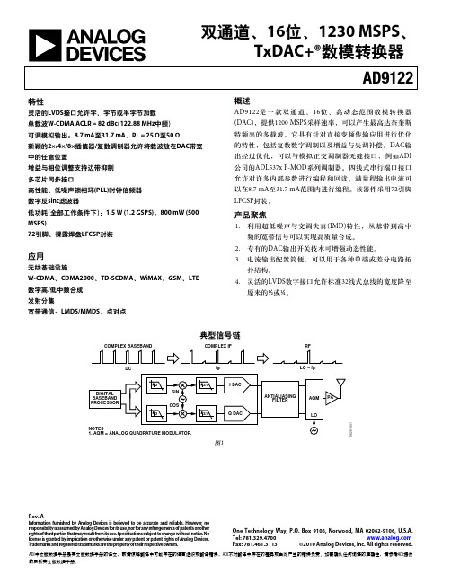
ADI中文版数据手册是英文版数据手册的译文,敬请谅解翻译中可能存在的语言组织或翻译错误,ADI不对翻译中存在的差异或由此产生的错误负责。如需确认任何词语的准确性,请参考ADI提供 的最新英文版数据手册。
AD9122
目录
特性 ....................................................................................................1 应用 ....................................................................................................1 概述 ....................................................................................................1 产品聚焦 ...........................................................................................1 典型信号链.......................................................................................1 修订历史 ...........................................................................................3 功能框图 ...........................................................................
C9120光纤交换机配置说明
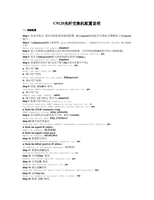
C9120光纤交换机配置说明一、初始配置Step 1 加电开机后,需对交换机做初始的配置,通过console线连接至交换机引擎模块上的console 接口。
Step 2 为administrator输入新密码。
(admin密码要求相对复杂点,一般要求为不少于8字符,有大小写、数字或特殊字符)Enter the password for admin: ZIQadmin1Step 3 进入安装模式.(根据提示进行相应的初始配置,任何时候按Ctrl-C即可终止初始配置)Would you like to enter the basic configuration dialog (yes/no): yesStep 4 再次为administrator输入新密码(默认密码为admin ).Enter the password for admin: ZIQadmin1Step 5 创建额外的用户帐号(用户账号ID必须为非数字字符)Create another login account (yes/no) [n]: yesa. 键入用户ID.Enter the user login ID: ZIQb. 键入用户密码.Enter the password for user_name: ZIQoperate1C. 确认用户权限.Enter the authentication:operatorStep 6 创建SNMPv3 帐号.Configure SNMPv3 Management parameters (yes/no) [y]: yesa. 键入用户名.SNMPv3 user name [admin]: adminb. 键入密码(最少8位). 默认为admin123.Step 7 配置可读写的SNMP community string。
Configure read-only SNMP community string (yes/no) [n]: nConfigure read-write SNMP community string (yes/no) [n]: yesa. Enter the SNMP community string.SNMP community string: snmp_communityStep 8 给交换机命名(最多32个字符,默认为switch).Enter the switch name:ZIQ_C9120sw1Step 9配置外部管理地址Continue with Out-of-band (mgmt0) management configuration? [yes/no]: yesa. Enter the mgmt0 IP address.Mgmt0 IP address:10.33.0.82b. Enter the mgmt0 subnet mask.Mgmt0 IP netmask: 255.255.255.0Step 10 配置默认网关.Configure the default-gateway: (yes/no) [y]: yesa. Enter the default gateway IP address.IP address of the default-gateway: 10.33.0.1Step 11 配置高级IP选项Configure Advanced IP options (yes/no)? [n]:noStep 12 启用Telnet 服务.Enable the telnet service? (yes/no) [y]: yesStep 13 启用SSH 服务.Enabled SSH service? (yes/no) [n]: yesStep 14 键入SSH类型Type the SSH key you would like to generate (dsa/rsa/rsa1)? dsaStep 15 选择key bitsEnter the number of key bits? (768 to 2048): 768Step 16 配置NTP 服务.Configure NTP server? (yes/no) [n]: yesStep 17 交换机端口默认状态(不包含管理以太端口)Configure default switchport interface state (shut/noshut) [shut]: no shutStep 18 配置交换机默认trunk 模式.Configure default switchport trunk mode (on/off/auto) [on]: offStep 19 配置交换机默认PortChannel auto-create 状态.Configure default port-channel auto-create state (on/off) [off]: offStep 20 配置交换机默认zone 策略.(如果选择deny,则未划入特定zone的端口将不属于任何一个zone,一般建议为permit,但在本案例中选用了deny)Configure default zone policy (permit/deny) [deny]: denyStep 21 配置交换机默认全zone set分布策略。
MTK 核心功能模块内部结构框图
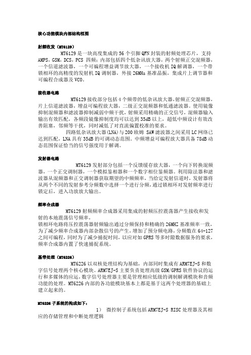
核心功能模块内部结构框图射频收发(MT6129)MT6129是一块高度集成的56个引脚QFN封装的射频处理芯片,支持AMPS,GSM,DCS,PCS 四频;内部包括四个低杂讯放大器,两个射频正交混频器,一个信道滤波器,一个可编程增益调节放大器,一个接收机IQ解调器,一个带锁相环的高精度的发射机IQ调制器,外接26MHz基准晶振,集成片上调节器和可编程合成器及VCO。
接收器电路MT6129接收部分包括4个频带的低杂讯放大器,射频正交混频器,片上信道滤波器,增益可编程放大器,二级正交混频器和低通滤波器。
使用镜像抑制混频器和滤波器抑制减弱中频干扰,射频采用精确的正交信号,混频器输入输出有效匹配,各频段镜像抑制度均可以达到35dB以上,超低中频设计有效改善阻塞,邻频等干扰,同时减低了对直流偏置校准的要求。
四路低杂讯放大器(LNA)与200欧姆 SAW滤波器之间采用LC网络已达到匹配,LNA具有35dB的可调动态范围。
中频增益可编程放大器具备78dB动态范围保证恰当的信号强度用于解调。
发射器电路MT6129发射部分包括一个反馈缓存放大器,一个向下转换混频器,一个正交调制器,一个模拟鉴相器和一个数字相位鉴频器。
利用除法器和滤波器从混频器和正交调制器获取期望的中频频率,当给定发射信道时,发射器将从两个不同的发射参考分频数中选择一个进行分频,通过锁相环对发射频率进行锁定后,进入功放放大输出。
频率合成器MT6129射频频率合成器采用集成的射频压控震荡器产生接收和发射的本地震荡信号频率,锁相环电路将压控震荡器射频输出通过分频保持和精确的26MHZ基准频率一致,为了减少频率合成器内部杂散信号的产生,增加了预分频电路,分频数在64-127之间可编程,同时为了减少捕捉时间,以应对如GPRS等多时隙数据服务的要求,频率合成器内置了快速捕捉系统。
基带处理(MT6226)MT6226以双核处理结构为基础,内部同时集成有ARM7EJ-S和数字信号处理两个核心模块。
IRFR9120N中文资料
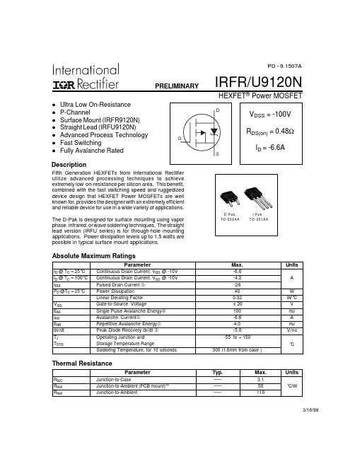
IRFR/U9120NPRELIMINARYHEXFET ® Power MOSFET3/16/98ParameterTyp.Max.UnitsR θJC Junction-to-Case––– 3.1R θJA Junction-to-Ambient (PCB mount)**–––50°C/WR θJAJunction-to-Ambient–––110Thermal ResistanceD -P ak T O -252A AI-P ak TO -251AAl Ultra Low On-Resistance l P-Channell Surface Mount (IRFR9120N)l Straight Lead (IRFU9120N)l Advanced Process Technology l Fast SwitchinglFully Avalanche RatedDescriptionParameterMax.UnitsI D @ T C = 25°C Continuous Drain Current, V GS @ -10V -6.6I D @ T C = 100°C Continuous Drain Current, V GS @ -10V -4.2A I DMPulsed Drain Current -26P D @T C = 25°C Power Dissipation 40W Linear Derating Factor 0.32W/°C V GS Gate-to-Source Voltage± 20V E AS Single Pulse Avalanche Energy 100mJ I AR Avalanche Current-6.6A E AR Repetitive Avalanche Energy 4.0mJ dv/dt Peak Diode Recovery dv/dt -5.0V/ns T J Operating Junction and-55 to + 150T STGStorage Temperature RangeSoldering Temperature, for 10 seconds300 (1.6mm from case )°CAbsolute Maximum RatingsFifth Generation HEXFETs from International Rectifier utilize advanced processing techniques to achieve extremely low on-resistance per silicon area. This benefit,combined with the fast switching speed and ruggedized device design that HEXFET Power MOSFETs are well known for, provides the designer with an extremely efficient and reliable device for use in a wide variety of applications.The D-Pak is designed for surface mounting using vapor phase, infrared, or wave soldering techniques. The straight lead version (IRFU series) is for through-hole mounting applications. Power dissipation levels up to 1.5 watts are possible in typical surface mount applications.PD - 9.1507AIRFR/U9120NIRFR/U9120NIRFR/U9120NIRFR/U9120NIRFR/U9120NIRFR/U9120NIRFR/U9120NIRFR/U9120NIRFR/U9120N。
华为视频会议解决方案
华为高清视讯系统技术方案建议书临时方案华为技术有限公司2016年10月9日使用说明(2016.10.9):1、模板使用时根据实际客户需求和方案设计,选择相应章节内容,与实际方案不相关的内容需删除;2、模板中使用说明、备注部分为内部参考,具体制作面向客户提交的方案时,需删除所有使用说明、备注部分。
目录1视讯技术发展及应用需求 (5)1.1技术发展 (5)1.1.1视频 (5)1.1.2音频 (5)1.1.3组网 (5)1.2应用需求 (6)1.2.1高临场感体验 (6)1.2.2低带宽高清 (6)1.2.3良好的网络适应性 (6)1.2.4良好的易用性 (6)1.2.5稳定性和可维护性 (7)1.2.6标准开放和融合互通 (7)1.2.7支持多种线路接入方式 (7)1.2.8客户化、可定制 (7)2华为高清视讯系统需求分析 (7)2.1华为背景简介 (7)2.2华为网络现状分析 (8)2.3华为客户需求分析 (8)3 华为高清视频系统设计方案建议 (8)3.1系统设计依据 (8)3.2系统设计原则 (11)3.3方案四SMC2.0+MCU96X0 ................................................................... 错误!未定义书签。
3.4系统组网方案四配置清单 ...................................................................... 错误!未定义书签。
4华为高清视频系统主要功能及特点 (12)4.1良好的高清晰音视频沟通体验 (12)4.1.1全高清108060端到端解决方案 (12)4.1.2高流畅性 (12)4.1.3强大全编全解处理能力,最大限度支持动态速率、协议适配 (13)4.1.4VME+H.264 HP 低带宽高清 (13)4.1.5H.264 SVC技术 (14)4.1.6高清1080P60FPS静态/动态双流 (14)4.1.7高保真,立体声,CD音质效果 (15)4.2丰富的会议召集模式 (15)4.2.1主叫呼集 (15)4.2.2匿名会议(电话会议模式) (16)4.2.3管理员调度 (16)4.2.4网络预约 (16)4.2.5视音频IVR导航与ad-hoc创建和加入会议 (16)4.2.6特服号入会 (16)4.2.7Outlook预约会议 (16)4.2.8云化资源池管理实现会议智能调度 (16)4.3良好的网络适应性 (18)4.3.1超强纠错(SEC 2.0-- Super Error Concealment) (18)4.3.2超强纠错(SEC 3.0-- Super Error Concealment) (18)4.3.3智能调速(IRC--Intelligent Rate Control) (19)4.3.4断线恢复(RoD--Reconnect on Disconnect) (19)4.3.5丢包重传(ARQ--Automatic Repeat reQuest) (20)4.4简单易用 (20)4.4.1用户界面简约时尚 (20)4.4.2PAD智能操控平台 (20)4.4.3丰富的会议控制功能 (20)4.4.4会议模板预置功能 (21)4.4.5字幕与横幅功能 (22)4.4.6一屏三显,节约投资 (22)4.4.7多视一流功能 (22)4.4.8无线辅流,轻松共享数据 (23)4.4.9支持WIFI呼叫及无线麦克 (23)4.4.10USB零配置 (24)4.4.11全景会场功能 (25)4.4.12多组多画面(on-table多画面) (25)4.4.13图形化操作界面 (25)4.4.14软终端随时随地接入会议 (26)4.4.153G-SDI接口实现1080P60fps远距离传输 (28)4.5安全稳定 (28)4.5.1产品成熟 (28)4.5.2系统稳定 (29)4.5.3多重加密 (30)4.5.4系统安全 (30)4.5.5资源池会议备份 (32)4.6管理维护方便 (33)4.6.1分级分权,大网维护简单 (33)4.6.2Nlog网络线路实时监控 (37)4.6.3支持WEB管理 (37)4.6.4系统设备拓扑图生成管理 (37)4.6.5系统设备配置批量升级及备份 (37)4.6.6系统告警和日志管理 (38)4.7标准互通 (39)4.7.1采用国际标准协议 (39)4.7.2支持TIP协议,与思科网真互通 (39)4.7.3华为视讯产品互联互通能力介绍 (39)4.7.4支持与微软UC系统互通 (41)4.7.5端到端IMS融合解决方案 (42)4.8丰富组网 (42)4.8.1支持多种接入方式 (42)4.8.2最大5级和超强多通道级联能力 (43)4.8.3支持大容量语音接入,满足在外人员接入视频会议需求 (43)4.8.4支持高清录制点播功能 (44)4.8.5支持软件化部署的管理平台 (48)4.8.6完善的公私网穿越解决方案 (49)4.9专业定制 .................................................................................................. 错误!未定义书签。
华为CX912交换机模块V100R001C10白皮书第13版日期2017-06-08说明书

Huawei CX912 Switch Module V100R001C10White PaperIssue13Date2017-06-08Copyright © Huawei Technologies Co., Ltd. 2017. All rights reserved.No part of this document may be reproduced or transmitted in any form or by any means without prior written consent of Huawei Technologies Co., Ltd.Trademarks and Permissionsand other Huawei trademarks are trademarks of Huawei Technologies Co., Ltd.All other trademarks and trade names mentioned in this document are the property of their respective holders.NoticeThe purchased products, services and features are stipulated by the contract made between Huawei and the customer. All or part of the products, services and features described in this document may not be within the purchase scope or the usage scope. Unless otherwise specified in the contract, all statements, information, and recommendations in this document are provided "AS IS" without warranties, guarantees or representations of any kind, either express or implied.The information in this document is subject to change without notice. Every effort has been made in the preparation of this document to ensure accuracy of the contents, but all statements, information, and recommendations in this document do not constitute a warranty of any kind, express or implied.Huawei Technologies Co., Ltd.Address:Huawei Industrial BaseBantian, LonggangShenzhen 518129People's Republic of ChinaWebsite:About This DocumentPurposeThis document describes the E9000 CX912 multi-plane switch module (CX912 for short) interms of its functions, advantages, appearance, specifications, internal networking, standardsand certifications. You can learn about the CX912 by reading this document.The product features and commands for the 10GE switching plane of the CX912 varyaccording to the software version. For details, see the documents listed in the following table.Intended AudienceThis document is intended for:l Huawei presales engineersl Channel partner presales engineersl Huawei enterprise presales engineersSymbol ConventionsThe symbols that may be found in this document are defined as follows.Change HistoryIssue 13 (2017-06-08)This issue is the thirteenth official release.Issue 12 (2017-03-27)This issue is the twelfth official release.This issue is the eleventh official release.Issue 10 (2016-11-22)This issue is the tenth official release.Issue 09 (2016-05-12)This issue is the ninth official release.Issue 08 (2015-07-17)This issue is the eighth official release.Issue 07 (2015-03-20)This issue is the seventh official release.This issue is the sixth official release.Issue 05 (2015-02-26)This issue is the fifth official release.Issue 04 (2014-09-15)This issue is the fourth official release.Issue 03 (2014-05-13)This issue is the third official release. Issue 02 (2014-04-08)This issue is the second official release. Issue 01 (2014-01-02)This issue is the first official release.White Paper ContentsContentsAbout This Document (ii)1 Overview (1)1.1 Functions (2)1.2 Advantages (10)1.3 Appearance (11)1.4 Ports (15)1.5 Indicators (20)1.6 Internal Chassis Networking (22)1.7 Software and Hardware Compatibility (24)1.8 Technical Specifications (26)2 Standards and Certifications (30)2.1 Standards Compliance (31)2.2 Certifications (33)1 Overview About This Chapter1.1 FunctionsThis topic describes the functions, supported protocols, and ports of the switching planes ofthe CX912 multi-plane switch module (CX912 for short).1.2 AdvantagesThe CX912 switch module provides high performance, high port density, and multipleswitching planes (GE/10GE/Fibre Channel(FC) switching), and supports large data centernetworks, high-performance stacking, on-demand configuration, flexible deployment, andrich data center features. In addition, the CX912 switch module is easy to deploy andmaintain.1.3 AppearanceThis topic describes the CX912 in terms of its appearance, panel, and installation positions inthe chassis.1.4 PortsThis topic describes the features, numbering rules, names, types, and quantities of the CX912ports.1.5 IndicatorsThis topic describes the indicators on the CX912.1.6 Internal Chassis NetworkingThis topic describes connection relationships between the CX912 and mezz modules oncompute nodes.1.7 Software and Hardware CompatibilityThis topic describes mezz modules that can work with the CX912 and pluggable modules andcables supported by ports on the CX912 panel.1.8 Technical SpecificationsThis topic describes the physical, environmental, power, and network switching specificationsof the CX912.1.1 FunctionsThis topic describes the functions, supported protocols, and ports of the switching planes ofthe CX912 multi-plane switch module (CX912 for short).CX912 is the switching control unit of a server. It provides data switching for compute nodesin the system and external management network ports and service ports. The CX912 providestwo independent planes, including the 10GE switching plane, and FC switching plane. Thetwo planes are physically isolated.The CX912 is installed in a rear slot of the E9000 chassis and is connected to compute nodes,storage nodes, and management modules through the midplane. It exchanges internal datapackets and control and management packets to ensure high-speed data transmission.For details about the functions provided by the 10GE switching plane, see Table 1-1. Fordetails about the functions provided by the FC switching plane, see Table 1-2.Table 1-1 10GE switching plane function descriptionTable 1-2 FC switching plane function description1.2 AdvantagesThe CX912 switch module provides high performance, high port density, and multipleswitching planes (GE/10GE/Fibre Channel(FC) switching), and supports large data centernetworks, high-performance stacking, on-demand configuration, flexible deployment, andrich data center features. In addition, the CX912 switch module is easy to deploy andmaintain.High Performance and High Port DensityUnderpinned by the leading hardware platform, the CX912 provides a high port density and aline-speed forwarding capability. It supports next-generation server applications that requiresuper high performance and density.The CX912 10GE switching plane provides sixteen 10GE SFP+ optical ports for connectingto upstream aggregation/core switches, forty 10GE electrical ports for interconnecting withhigh-performance compute nodes, eight 8G FC optical ports for connecting FC storage areanetworks (FC SANs), and two 40GE ports for interconnecting with switch modules.The CX912 10GE switching planes support low-latency forwarding, providing a switchingcapability of 1.28 Tbit/s (throughput) and line-speed forwarding for Ethernet frames. Theforwarding latency for layer 2 Ethernet frames in cut through mode is less than 1.5 us.The CX912 FC switching plane provides a line-speed switching capability of 192 Gbit/s (384Gbit/s throughput).Multiple Switching Planes and Support for Large Data Center NetworksThe CX912 provides table entries of high specifications: a maximum of 131,072 MACaddress entries and 16,384 forwarding information bases (FIBs) entries.High-Performance Stacking, Easy Deployment, and Simple MaintenanceThe CX912 supports a stacking system of four devices. It has the following advantages:l High performance: A single stacking system can provide more than thirty-two 10GEports.l High bandwidth: The stacking system supports 160Gbps stacking bandwidth.l Easy deployment and maintenance:–Pre-deployment and offline configuration are supported. The system can be pre-planned and pre-configured. Devices can be added as required, supporting plug-and-play.–The slot ID of a device is the ID in the stacking system, facilitating identificationand maintenance.–Indicators on the front panel indicate the role and status of a stacking system. Thestacking system can be maintained without a terminal.l Simple upgrade operations: The stacking system supports quick and automatic software upgrades, simplifying upgrade operations and reducing upgrade workload.–Rapid software upgrades: When two switch modules are stacked, the standbyswitch module is upgraded before the active switch module. This ensures that atleast one switch module is operating.–Automatic software upgrades: When two switch modules are stacked, the softwareversion is automatically synchronized from the active switch module to the standbyone.On-Demand Configuration and Flexible DeploymentThe FC switching plane of the CX912 provides eight 8G FC ports. Four of the ports areactivated by default, and the other four ports require licenses for activation, which addressesdiverse user needs.Rich Data Center Featuresl Supports virtualization/virtual machine (VM) access.–Supports server virtualization, improving data center utilization.–Supports virtual sensors. During migration of VMs, network policies can beautomatically migrated using virtual sensors so that network resources can beallocated as required. Working with the layer 2 network, VMs can be freelymigrated within the data center.l Supports the Transparent Interconnection of Lots of Links (TRILL) protocol.–Complying with the Internet Engineering Task Force (IETF) standard, the TRILLprotocol supports ultra-large networks and flexible networking modes.–The TRILL protocol supports load balancing between paths, so that traffic can beshared by multiple paths according to service requirements.–The TRILL protocol supports fast network convergence. Any changes on thenetwork can be quickly sensed and fast convergence is performed.1.3 AppearanceThis topic describes the CX912 in terms of its appearance, panel, and installation positions inthe chassis.AppearanceFigure 1-1 shows the CX912.Figure 1-1 CX912Installation PositionsThe CX912 can be installed in the four slots at the rear of the E9000 chassis. The four slots are 1E, 2X, 3X, and 4E, as shown in Figure 1-2.Figure 1-2 Installation positions and slotsPanelFigure 1-3 shows the CX912 panel.Figure 1-3 Panel1Product Model2Customization label (with an ESNlabel)3BMC serial port4Power indicator5Healthy indicator6Offline button/indicator7SYS serial port8GE electrical port (reserved)9Connection status indicator of the GEelectrical port 10Data transmission status indicator ofthe GE electrical port1110GE optical port12Connection status indicator of the10GE optical port13Data transmission status indicator of the10GE optical port148G FC optical port15Connection status indicator of the 8G FC optical port 16Diagnosis status indicator of the 8GFC optical portESNsAn Equipment Serial Number (ESN) is a string that uniquely identifies a server. An ESN is required when you apply for technical support from Huawei.Figure 1-4 shows the ESN format.Figure 1-4 ESN example1.4 PortsThis topic describes the features, numbering rules, names, types, and quantities of the CX912ports.The CX912 provides ports for users to operate and configure. The ports are used to send andreceive data.The CX912 ports are numbered in Slot number/Subcard number/Port number format.l Slot number: indicates the slot number of the current switch module. Its value rangesfrom 1 to 4, from left to right mapping to slot numbers 1E, 2X, 3X, and 4E.l Subcard number: indicates the number of a subcard supported by service ports. Thevalue ranges from 1 to 19.l Port number: indicates the sequence number of a port on a subcard.The FC optical ports on the CX912 panel are numbered from 1 to 8.For details about the value options, see Figure 1-5, Table 1-3, Table 1-5 and Table 1-6.For example, if the CX912 is in slot 2X, the first GE optical port on the upper right of thepanel is numbered GE 2/17/4, as shown in Figure 1-5.Figure 1-5 Port naming rulesTable 1-3 describes the ports on the CX912.Table 1-3 External portsTable 1-4 describes the internal ports on the onboard GE switching plane of the CX912. Table 1-4 Internal ports on the onboard GE switching planeTable 1-5 describes the internal ports on the CX912 10GE switching plane.Table 1-5 Internal ports on the 10GE switching planeTable 1-6 describes the internal ports on the CX912 FC switching plane.Table 1-6 Internal ports on the FC switching planeThe internal FC interface rate must be set to 8 Gbit/s.1.5 IndicatorsThis topic describes the indicators on the CX912.You can observe the indicators to determine the current operating status of the CX912. Table 1-7 describes the indicators on the CX912 panel.Table 1-7 Indicators1.6 Internal Chassis NetworkingThis topic describes connection relationships between the CX912 and mezz modules oncompute nodes.For details about the networking of the CX912 and mezzanine cards on compute nodes, seeE9000 Blade Server Mezz Module-Switch Module Interface Mapping Tool.Figure 1-6 shows the internal chassis networking for the CX912 and compute nodes. Ports oncompute nodes for connecting to the CX912 are provided by two mezz modules. Themapping between the CX912 and the NIC and mezz modules is described as follows:l Mezz 1 connects to the 10GE switching planes and FC switching planes of the CX912s in slots 2X and 3X.l Mezz 2 connects to the 10GE switching planes and FC switching planes of the CX912s in slots 1E and 4E.Figure 1-6 Mapping between the CX912 and mezz modules on compute nodesMapping between the CX912 and ports on the MZ912The two 10GE ports (ports 1 and 2) on the MZ910 map to the 10GE switching planes of the CX912s in slots 3X and 2X respectively, as shown in Figure 1-7.The8G FC ports (ports 3 and 4) on the MZ912 map to the FC switching planes of the CX912s in slots 3X and 2X respectively.Figure 1-7 Mapping between the CX912 and ports on the MZ9121.7 Software and Hardware CompatibilityThis topic describes mezz modules that can work with the CX912 and pluggable modules andcables supported by ports on the CX912 panel.For details about the software and hardware that are compatible with the CX912, see HuaweiServer Compatibility Checker.Supported Mezz ModulesThe CX912 connects to mezz modules of compute nodes. Table 1-8 describes models andspecifications of the supported mezz modules.Table 1-8 Supported mezz modulesSupported Pluggable Modules and CablesTable 1-9 Supported pluggable modules and cablesThe CX912 supports multiple pluggable optical modules, fibers, and network cables. You canchoose the modules and cables based on site requirements.l The CX912 provides the following functions for GE applications:–Provides RJ45 ports for connecting to twisted-pair cables.–Provides SFP+ optical ports that support single-mode and multi-mode SFP+ opticalmodules.–Supports SFP electrical modules.l The CX912 provides the following functions for 10GE applications:–Provides SFP+ optical ports and supports single-mode and multi-mode SFP+optical modules.–Supports 10GE DAC cables, which can be 7 m or 10 m active DAC cables or 1 m,3 m, or 5 m passive DAC cables.l The CX912 provides the following functions for FC applications: provides SFP+ optical ports; uses single-mode and multi-mode 8G SFP+ optical modules; supports 4 Gbit/s and8 Gbit/s.FC ports of the CX912 support only single-mode and multi-mode Brocade swappable optical modules.1.8 Technical SpecificationsThis topic describes the physical, environmental, power, and network switching specificationsof the CX912.Table 1-10 describes the technical parameters of the CX912, and Table 1-11 describes thenetwork switching specifications of the CX912.For details about the FC switching plane switching performance, see theMX210&MX220_Fabric_OS_Administrator_Guide.Table 1-10 Technical specificationsTable 1-11 Network switching specifications2 Standards and Certifications About This Chapter2.1 Standards ComplianceThis topic describes the international and industrial standards and communication protocolsthat the CX912 complies with.2.2 CertificationsThis topic describes the certifications that the E9000 has passed.2.1 Standards ComplianceThis topic describes the international and industrial standards and communication protocolsthat the CX912 complies with.International StandardsTable 2-1 lists the international standards.Table 2-1 Standards and protocol complianceIndustrial StandardsTable 2-2 lists the industrial standards.Table 2-2 Industrial standardsCommunication ProtocolsTable 2-3 lists the communication protocols.Table 2-3 Communication protocols2.2 CertificationsThis topic describes the certifications that the E9000 has passed.Table 2-4 lists the certifications.Table 2-4 CertificationsHuawei CX912 Switch ModuleWhite Paper 2 Standards and CertificationsIssue 13 (2017-06-08)Huawei Proprietary and ConfidentialCopyright © Huawei Technologies Co., Ltd.34。
NUC微控制器产品系列说明书

M251 Feature
。 Arm® Cortex®-M23 。 运行速度可达 48 MHz
M252 Feature
。 USB 2.0 全速设备无需外 挂晶振
M253 Feature
。 USB 2.0 全速设备无需外 挂晶振
。 高达五路 UART 。 CAN FD x1
2
Low Power
TrustZone
AEC-Q100
Market Trend
随着电子应用对低功耗或电池供电的需 求日益增加,现今的应用必须尽量降低 能源消耗,甚至在极端情况下,可能需 要倚赖单颗电池来维持长达 15 至 20 年 运转
低功耗应用情景包含手持式设备、居家、 AIoT、IIoT (工业物联网) 等应用情景, 使用范围十分广泛
(Programmable Serial I/O) • USB 2.0 全速装置无需外挂晶振 • 独立的 RTC 电源 VBAT 管脚
Highlight
• 支持 1.8 V ~ 5.5 V 串行接口,可连接不同电压 装置
*USCI: Universal Serial Control Interface Controller
C
1.8 3.3 5 M253
CU
3.3 5 M071
1.8 3.3 5 M252
U
3.3 5 M051
1.8 3.3 5 M251
3.3 5 Mini51
3.3 5 3.3 5
1.8 3.3 Nano100
M480 M460 M471 M453 M452 M451
E CU E CU
U C
U
Arm9™
高压原边控制恒流模式LED驱动开关器XD9125说明书

产品描述XD9125 是一款内部高度集成的原边控制、恒流模式LED 驱动开关品。
在同一个晶圆上,XD9125集成有650V 功率MOSFET 和控制器。
此外,芯片还集成有高压启动电路和变压器退磁检测电路,支持无辅助绕组设计。
芯片采用带线电压补偿的PFM 控制,实现LED 恒流控制。
XD9125集成有完备的保护功能以保障系统安全可靠的运行,如VDD 欠压保护功能、逐周期电流限制、过热保护、LED 开路和短中保护等。
SOP-8主要特点■ 内部集成高压 650V MOSFET ■ ±4%恒流精度 ■ 超低工作电流 ■ 无辅助绕组设计 ■ 集成式过热功率补偿■集成式高压电流源提高启动速度 ■ 集成式线电压补偿优化调整率■内部保护功能:∙ LED 开路和短路保护 ∙ 芯片过热保护 ∙ 逐周期电流限制 ∙ 前沿消隐 ∙ 脚位悬空保护 ∙ VDD 脚欠压保护 ■封装类型SOP-8应用■LED 蜡烛灯 ■ LED 球泡灯 ■ LED PAR 灯 ■ LED 射灯■及其它LED 照明等等典型应用图注:以上线路及参数仅供参考,实际的应用电路请在充分的实测基础上设定参数。
管脚封装管脚封装图适宜功率参考表管脚功能描述订购信息D芯片内部功能框图极限参数(备注1)推荐工作条件(备注2)参数参数范围单位适宜工作环境-40 to 85 o C电气参数(无特别说明,环境温度为T A = 25O C)备注1:超出列表中“极限参数”可能会对器件造成永久性损坏。
极限参数为应额定值。
在超出推荐的工作条件和应力的情况下,器件可能无法正常工作,所以不推荐让器件工作在这些条件下。
过度暴露在高于推荐的最大工作条件,可能会影响器件的可靠性。
备注2:在超出以上参数的条件下,无法保障芯片的正常运行。
备注3:参数取决于实际设计,在批量生产时进行功能性测试。
参数特性曲线功能描述XD9125是一款内部高度集成的降压型准谐振式LED 恒流驱动开关器。
CH9126技术手册
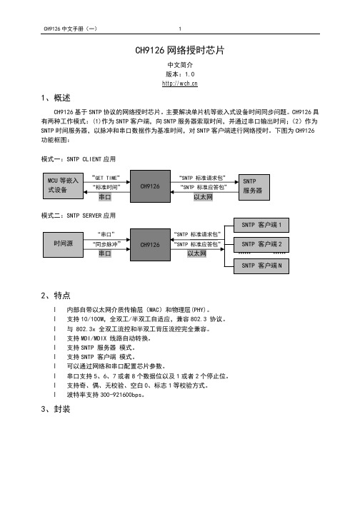
CH9126网络授时芯片中文简介版本:1.01、概述CH9126基于SNTP协议的网络授时芯片。
主要解决单片机等嵌入式设备时间同步问题。
CH9126具有两种工作模式:(1)作为SNTP客户端,向SNTP服务器索取时间,并通过串口输出时间;(2)作为SNTP时间服务器,以脉冲和串口数据作为基准时间,对SNTP客户端进行网络授时。
下图为CH9126功能框图:模式一:SNTP CLIENT应用2、特点l内部自带以太网介质传输层(MAC)和物理层(PHY)。
l支持10/100M,全双工/半双工自适应,兼容802.3 协议。
l与 802.3x 全双工流控和半双工背压流控完全兼容。
l支持MDI/MDIX 线路自动转换。
l支持SNTP 服务器模式。
l支持SNTP 客户端模式。
l可以通过网络和串口配置芯片参数。
l串口支持5、6、7或者8个数据位以及1或者2个停止位。
l支持奇、偶、无校验、空白0、标志1等校验方式。
l波特率支持300-921600bps。
3、封装芯片型号芯片封装名称描述CH9126 LQFP64M LQFP封装:64脚:本体10x10mm4、引脚CH9126引脚号引脚名称类型引脚说明2、12、17、21、29、40、42、45、63VCC33 电源 3.3V 正电源输入端,外接0.1uF电源退耦电容6、19、28、43、54、64 VCC18 电源 1.8V 正电源输入端,外接0.1uF电源退耦电容3、9、13、18、20、37、41、44、48GND 电源公共接地端14、15、16、22、23、24、25、26、27、32、33、34、35、38、39、46、47、49、50、51、53、55、56、61、62NC - 保留引脚,悬空1 RSETE 输入外接18K 电阻到地端4 RXP 以太网信号以太网RXP信号5 RXN 以太网信号以太网RXN信号7 TXP 以太网信号以太网TXP信号8 TXN 以太网信号以太网TXN信号10 XI 输入晶体振荡的输入端,需要外接30MHz 晶体11 XO 输出晶体振荡的反相输出端,需要外接30MHz晶体30 PULSEIN 输入标准1秒脉冲输入31 RESV 输入预留调试脚,悬空36 RSTI 输入外部复位输入,低电平有效,内置上拉电阻52 ELINK 输出以太网连接通讯指示灯驱动引脚57 RXD 输入异步串口的串行数据输入,内置上拉电阻58 TXD 输出异步串口的串行数据输出59 RESET 输入恢复出厂设置,芯片上电检测,低电平有效60 PULSEOUT 输出标准1秒脉冲输出5、功能说明5.1. 功能简介时钟源是SNTP服务器时,CH9126工作在SNTP CLIENT模式,对时时间间隔为10min,出错会重试3次,每次等待的时间为500ms。
CBM培训资料

Engineer ITControl Builder MVersion 3.2Getting Started工业工程IT控制应用开发版本 3.2入门山东恒拓科技开展本资料是由山东恒拓科技开展〔ABB系统集成商〕内部员工参考CBM原版说明书翻译整理而成,本书主要用于内部参考学习及客户培训使用,未经山东恒拓科技开展许可的前提下,其他任何人员不可擅自复制,传播。
译者:孔祥玉。
本文献中的所有信息可能会在没有通知的前提下发生修改,并且ABB拥有对所有信息的解释权。
对于本文献中可能出现的任何错误,ABB不负任何法律责任。
在本文献的使用过程中,ABB对于因自然或非自然因素而产生的直接的、间接的、特殊的和附带的所有损失不负任何责任,且ABB对本文献中软件和硬件的描述中产生的任何损失不负任何责任。
在没有ABB的许可之下,本文献或其中的章节不可进行复制,且其中内容不可授予第三方或任何未授权的应用。
版权拥有© 1999 ABB保存所有版权发行:2002年12月文献编号:3BSE 028 807 R201 Rev B商标本文中使用到的注册和商标:Windows 微软公司注册ActiveX 微软公司注册PostScript Adobe Systems Inc. 注册Acrobat Reader Adobe Systems Inc. 注册Industrial IT ABB 注册第一部Control Builder M目录关于本书简介 (6)第一章–介绍Control Builder M产品总览........................................................................ ... ... . (7)编程语言....................................................... ... ... ... ... ... . (7)工程开发器.................................................... ... . (7)库................................ ... ... (8)安装要求....................................................................... ....................... . (8)可以支持的控制器组态.......... .. ....................................... ....................... . (9)Control Builder和控制器组态................................................. (10)分散控制................ ....... ....... ....... ....... ....... ........................... ..................... .. (11)Control Builder现有版本及其差异........................................ (12)第二章–安装Control Builder M................ ..... ..... ..... ..... .. .. ... .. (13)逐步安装指南........................................................ .. .. ... (14)TCP/IP 网络协议................................................. ..... ..... ..... .. (14)设置...................................................................................... ...... ...... ...... .. (15)启动................... ..... ..... ..... ..... . (15)AC800M/C的MMS效劳器............................................................. . (15)添加删除程序...................... ..... ..... ..... .. (15)第三章–培训导言.............................. ..... ..... ..... .. (17)开始新工程.......................................... ......... ......... (17)工程开发器...................................................................... . (18)标题菜单工具 (36)库...................................................................................................................... .. (37)控制器.................................................................................................................... . 38 任务. (40)应用 (40)变量间接 (43)变量声明〔定义〕 (43)局部变量 (44)模拟 (47)关闭Control Builder M (49)第四章–举例– Shop Doors简介 (51)选择模板 (52)声明变量和数据类型 (53)变量声明 (54)使用ST语言编写代码 (56)改变编程语言 (56)声明功能块 (57)划分程序功能段 (58)代码输入 (59)模拟 (62)硬件组态 (64)连接I/O通道和应用 (65)第五章–下装和测试简介 (71)通过串行电缆进行操作系统下装 (71)给冗余控制器下装操作系统 (73)设定IP地址 (74)通过以太网下装工程 (77)在线测试 (91)附录AC800 M/C的OPC效劳器简介 (91)自动启动OPC效劳器OPC的组态面板第二部AC800M Controller Hardware目录关于本书第一章–简介产品总览 (27)AC 800M 控制器的突出特性 (38)第二章–安装安装环境要求 (41)电缆 (43)电源 (44)防护等级 (46)将AC 800M单元安装于标准DIN-Rail导轨 (47)安装PM856/860/861/TP830 控制器单元〔单独〕 (54)安装PM861/TP830 控制器单元〔冗余〕 (62)安装PROFIBUS DP 通讯单元,CI851/TP851 (65)安装RS232-C通讯单元, CI853/TP853 (69)安装PROFIBUS DP-V1通讯单元, CI854/TP854 (70)安装CEX-bus电缆 (74)安装ModuleBus 电缆 (75)安装SD82x 供电电源 (76)安装主断路器 (77)安装SS822冗余电源选择模块 (79)安装SB821外部电池 (83)安装I/O 单元 (83)柜体安装 (84)第三章–组态简介 (89)连接到Control Builder M (89)连接到控制网 (90)通讯方式 (91)控制器IP地址 (93)在Control Builder M设置冗余控制器 (93)I/O系统 (94)驱动系统 (98)供电系统 (100)柜体中的电源模块 (101)柜外电源设备Powering Field Equipment outside the Cabinet (101)外部+24 V DC 电源 (103)第四章–操作AC 800M 控制器(PM856/860/861) (107)启动 (110)启动模式 (110)自动切换到冗余后备控制器 (112)AC 800M系统运行检查 (113)观察单控制器的运行 (113)观察冗余控制器的运行 (115)第五章–维修维修频率 (117)更换电池 (118)内部电池 (118)SB821外部电池单元 (120)在线插拔 (124)更换PM861冗余控制器 (124)维修步骤 (125)查找问题 (126)PM856/860/861控制器单元 (126)PM861 CPU冗余单元 (127)内部电池/ SB821外部电池 (127)PROFIBUS DP – CI851 (128)RS232-C Channels – CI853 (132)PROFIBUS DP-V1 – CI854 (133)Table of Contents附录–硬件单元PM856/PM860和TP830 –控制器单元 (137)技术数据 (138)性能数据 (142)PM861 and TP830 –控制器单元 (143)技术数据 (144)性能数据 (146)CI851 和TP851 – PROFIBUS DP单元 (147)CI853 和TP853 – RS232-C单元 (155)CI854 和TP854 – PROFIBUS DP-V1 Interface (159)电源单元–SD821, SD822 和SD823 (175)SS822 – (冗余电源选择单元) (183)SB821外部电池 (187)其他 (189)TB850 -- CEX-bus终端电阻 (189)TB851 -- CEX-bus终端电阻 (190)TB807 ModuleBus终端电阻 (191)TB852 RCU 连接终端电阻 (191)TK850 CEX-bus 外部电缆 (191)TK851 RCU连接电缆 (191)TK853电缆 (192)TK212工具电缆 (193)第一部Control Builder M关于本书简介欢迎使用本软件〔Control IT for AC 800M/C〕----一个真正全开放的工业控制开发系统。
最新-黑白CMOS图像传感器OV920190的原理及应用 精品

黑白CMOS图像传感器OV9120的原理及应用摘要本文阐述了图像传感器的一般特征,详细介绍了黑白图像传感器芯片9120的性能、特点及工作原理,给出了9120在图像采集处理中的具体应用实例。
关键词图像传感器;9120;图像采集1概述随着CMOS技术的发展及市场需求的增加,CMOS图像传感器得以迅速发展。
CMOS图像传感器具有高度集成化、成本低、功耗低、单一工作电压、局部像素可编程、随机读取等优点,适用于超微型数码相机、便携式可视电话、PC机电脑眼、可视门铃、扫描仪、摄像机、安防监控、汽车防盗、机器视觉、车载电话、指纹识别、手机等图像领域。
本文介绍的是由美国OmniVision技术公司生产的OV9120黑白CMOS图像传感器,它采用独特的传感器专利工艺技术和先进的算法algorithms解决了先前CMOS感光器件固定图像噪声FPN的限制。
因而可广泛应用于数字静止摄像、视频会议、视频电话、计算机视觉、生物测量等领域。
2引脚功能OV9120采用48脚LCC封装,其引脚排列如图1所示。
范文先生网收集整理3结构性能及工作原理3.1内部结构OV9120内置1312×1036分辨率的镜像阵列、10位A/D转换器、可调视频窗、SCCE接口、可编程帧速率控制、可编程/自动曝光增益控制、内外帧同步、亮度均衡计数器、数字视频端口、定时产生器、黑电平校准及白平衡控制等电路。
其内部结构如图2所示。
3.2性能特点OV9120是135万像素1312×1036、1/2英寸的CMOS图像传感芯片,它采用SXGA/VGA格式,最大帧速率可达到30帧/sVGA,该芯片将CMOS光感应核与外围辅助电路集成在一起,同时具有可编程控制功能。
m,像素尺寸,5.2μm×5.2μm;●信噪比>54dB;●增益调整范围0~24dB;●SXGA输出时,阵列大小为1280×1024,VGA输出时,阵列大小为640×480;●供电电源电压为直流3.3V和2.5V;●暗电流28mV/s;●动态范围60dB。
MC9S12_datasheet中文

目录 .................................................................................................................................................. I 第一章 PWM模块 ...........................................................................................................................1 第一节 PWM模块介绍 .........................................................................................................1 第二节 PWM寄存器简介 .......................................................................2 2.1 PWME寄存器 ........................................................................................................2 2.2 PWMPOL寄存器...................................................................................................2 2.3 PWMCLK寄存器 ..................................................................
芯片9121参数

芯片9121参数
芯片9121是一款集成了TCP/IP协议栈的芯片,具体参数如下:
1. 具有TCPCLIENT、TCP SERVER、UDP 3种工作模式,可实现网络数据
包和串口数据的双向透明传输。
2. 串口波特率最高可支持到921600bps,同时支持300bps\~921600bps。
3. 内部自带以太网介质传输层(MAC)和物理层(PHY),支持10/100M,全双工/半双工自适应以太网接口,兼容IEEE 协议。
4. 支持MDI/MDIX线路自动转换。
5. 串口TTL电平,兼容和5V,支持全双工和半双工串口通讯,支持RS485收发自动切换,还支持虚拟串口。
6. 该芯片还具有短路保护、热停堆等安全特性,能在-40°C至+85°C的温
度范围内工作。
希望以上内容对您有帮助,如需了解更多芯片9121相关信息,建议咨询芯片技术人员或查看芯片规格书。
铁路客运专线旅服系统需求说明书v1.1

铁路客运专线旅服系统集成管理平台需求说明书修订记录目录第一部分引言 (13)第一章背景说明 (13)第二章参考资料 (13)第三章定义、术语和缩写词 (14)第四章编写说明 (14)第二部分项目概述 (15)第一章项目背景 (15)1新的运输市场形势 (15)2客运专线运营特点 (15)2.1高速度 (15)2.2高密度 (15)2.3大客流 (15)2.4网络化 (15)2.5换乘多 (16)2.6安全可靠 (16)3既有线旅服系统情况 (16)第二章系统目标 (16)第三章总体分析 (17)1业务概述 (17)2业务实体分析 (18)2.1旅客需求 (18)2.1.1购票 (18)2.1.2进站 (19)2.1.3候车 (20)2.1.4上车 (21)2.1.5下车 (22)2.1.6出站 (23)2.1.7接站 (24)2.2工作人员需求 (26)2.2.1客运值班员 (26)2.2.2检票员 (28)2.2.3站台工作人员 (29)2.2.4售票值班员 (31)2.2.5客运值班操作员-广播员 (33)2.2.6客运值班操作员-非广播员 (35)2.2.7客运值班站长 (37)2.2.8维护值班员-设备维护 (39)2.2.9维护值班员-业务维护 (41)2.2.10消防值班室工作人员 (42)2.2.11公安值班室工作人员 (43)4功能结构关系 (47)5与外部系统关系 (48)第三部分综合到发模块 (51)第一章由来和背景 (51)第二章目标和主要研究内容 (51)1目标 (51)1主要研究内容 (51)2业务实体分析 (52)3业务流程分析 (52)3.1正常业务流程 (52)3.2变更业务流程 (53)4功能结构关系 (55)第三章功能模块 (56)1模板制作 (56)1.1功能描述 (56)1.2实现方案 (56)1.2.1日期模板 (56)1.2.2列车模板 (57)1.2.3列车运行方式模板 (59)1.2.4晚点模板 (60)1.2.5广播专题模板 (61)1.2.6导向专题模板 (62)1.3性能和需求 (64)1.4假设和约束 (64)2计划生成 (64)2.1功能描述 (64)2.2实现方案 (64)2.3性能和需求 (64)2.4假设和约束 (64)3冲突检查 (65)3.1功能描述 (65)3.2实现方案 (65)3.3性能和需求 (66)3.4假设和约束 (66)4计划执行 (66)4.1功能描述 (66)4.2实现方案 (66)4.3性能和需求 (68)4.4假设和约束 (68)第四部分广播模块 (69)第一章由来和背景 (69)1目标 (69)2主要研究内容 (69)3业务实体分析 (70)4业务流程分析 (77)4.1业务视图 (77)4.2业务流图 (77)5功能结构关系 (79)第三章功能模块 (81)1广播区分组功能分析 (81)1.1功能描述 (81)1.2业务流程 (82)1.3实现方案 (82)1.3.1新建广播分组 (83)1.4性能需求 (84)1.5假设和约束 (84)2广播选区功能分析 (84)2.1功能描述 (84)2.2业务流程 (85)2.3实现方案 (85)2.3.1手动直接选区 (85)2.3.2利用广播分组功能选区 (86)2.4业务项描述 (86)2.5性能需求 (86)2.6假设和约束 (86)3操作员选区人工广播分析 (86)3.1功能描述 (86)3.2业务流程 (87)3.3实现方案 (87)3.4业务项描述 (87)3.5性能需求 (87)3.6假设和约束 (87)4专题广播功能分析 (88)4.1功能描述 (88)4.2业务流程 (88)4.3实现方案 (88)4.4业务项描述 (89)4.5性能需求 (89)4.6假设和约束 (89)5临时广播功能分析 (89)5.1功能描述 (89)5.2业务流程 (89)5.3实现方案 (90)5.4业务项描述 (90)5.6假设和约束 (91)6设备状态及报警监视功能分析 (91)6.1功能描述 (91)6.2业务流程 (91)6.3实现方案 (91)6.4业务项描述 (92)6.5性能需求 (92)6.6假设和约束 (92)7其他音源选择功能分析 (93)7.1功能描述 (93)7.2业务流程 (93)7.3实现方案 (93)7.4业务项描述 (93)7.5性能需求 (94)7.6假设和约束 (94)8广播监听功能分析 (94)8.1功能描述 (94)8.2业务流程 (94)8.3实现方案 (94)8.4业务项描述 (95)8.5性能需求 (95)8.6假设和约束 (95)9优先级控制功能分析 (95)9.1功能描述 (95)9.2业务流程 (95)9.3实现方案 (95)9.4业务项描述 (96)9.5性能需求 (96)9.6假设和约束 (96)10数据转发功能分析 (96)10.1功能描述 (96)11综合到发计划联动功能分析 (96)11.1功能描述 (96)第五部分导向模块 (97)第一章由来和背景 (97)第二章目标和主要研究内容 (97)1目标 (97)2主要研究内容 (97)3业务实体分析 (98)4业务流程分析 (100)4.1业务视图 (100)4.2业务信息流程图 (100)5功能结构关系 (102)第三章功能模块 (103)1选区功能 (103)1.1功能描述 (103)1.2业务流程 (103)1.3实现方案 (103)1.4业务项描述 (105)1.5性能需求 (105)1.6假设和约束 (105)2专题插播业务分析 (106)2.1功能描述 (106)2.2业务流程 (106)2.3实现方案 (106)2.4业务项描述 (107)2.5性能需求 (107)2.6假设和约束 (107)3人工插播业务分析 (108)3.1功能描述 (108)3.2业务流程 (108)3.3实现方案 (108)3.4业务项描述 (109)3.5性能需求 (109)3.6假设和约束 (109)4信息转发业务分析 (110)4.1功能描述 (110)4.2业务流程 (110)4.3实现方案 (110)4.4业务项描述 (111)4.5性能需求 (111)4.6假设和约束 (111)5售票窗口信息编辑业务分析 (111)5.1功能描述 (111)5.2业务流程 (111)5.3实现方案 (112)5.4业务项描述 (113)5.5性能需求 (113)5.6假设和约束 (113)6设备监控业务分析 (113)6.1功能描述 (113)6.2业务流程 (113)6.3实现方案 (114)6.4业务项描述 (115)6.5性能需求 (115)7设备分组业务分析 (115)7.1功能描述 (115)7.2业务流程 (115)7.3实现方案 (116)7.4业务项描述 (117)7.5性能需求 (117)7.6假设和约束 (117)8与广播系统同步业务分析 (117)8.1功能描述 (117)8.2业务流程 (117)8.3实现方案 (118)8.4业务项描述 (118)8.5性能需求 (118)8.6假设和约束 (118)第六部分监控模块 (119)第一章由来和背景 (119)第二章目标和主要研究内容 (119)1目标 (119)2主要研究内容 (119)3业务实体分析 (120)4业务流程分析 (121)4.1业务信息流程图 (121)4.2业务流图 (121)5功能结构关系 (122)第三章功能模块 (122)1摄像机选择 (122)1.1功能描述 (122)1.2业务流程 (123)1.3实现方案 (123)1.4业务项描述 (123)1.5性能需求 (124)1.6假设和约束 (124)2图像显示 (124)2.1功能描述 (124)2.2业务流程 (124)2.3实现方案 (124)2.4业务项描述 (125)2.5性能需求 (126)2.6假设和约束 (126)3画面缩放 (126)3.1功能描述 (126)3.2业务流程 (126)3.4业务项描述 (127)3.5性能需求 (127)3.6假设和约束 (127)4云台控制 (127)4.1功能描述 (127)4.2业务流程 (127)4.3实现方案 (128)4.4业务项描述 (128)4.5性能需求 (129)4.6假设和约束 (129)5预置位调用播 (129)5.1功能描述 (129)5.2业务流程 (129)5.3实现方案 (129)5.4业务项描述 (130)5.5性能需求 (130)5.6假设和约束 (130)6轮巡组编辑 (130)6.1功能描述 (130)6.2业务流程 (130)6.3实现方案 (130)6.4业务项描述 (132)6.5性能需求 (132)6.6假设和约束 (133)7轮巡组调用 (133)7.1功能描述 (133)7.2业务流程 (133)7.3实现方案 (133)7.4业务项描述 (134)7.5性能需求 (134)7.6假设和约束 (134)8声音监听业务分析 (134)8.1功能描述 (134)8.2业务流程 (134)8.3实现方案 (135)8.4业务项描述 (135)8.5性能需求 (135)8.6假设和约束 (136)9图像抓拍 (136)9.1功能描述 (136)9.2业务流程 (136)9.3实现方案 (136)9.4业务项描述 (136)9.6假设和约束 (137)10设备监视 (137)10.1功能描述 (137)10.2业务流程 (137)10.3实现方案 (137)10.4业务项描述 (138)10.5性能需求 (138)10.6假设和约束 (138)第七部分大屏幕模块 (139)第一章大屏幕的由来和背景 (139)第二章大屏幕的目标和主要研究内容 (139)1目标 (139)2主要研究内容 (139)3业务实体分析 (140)4业务流程分析 (142)4.1业务视图 (142)4.2业务流图 (142)5功能结构关系 (143)第三章功能模块 (144)1大屏幕布局编辑 (144)1.1功能描述 (144)1.2业务流程 (144)1.3实现方案 (145)1.4业务项描述 (147)1.5性能需求 (147)1.6假设和约束 (147)2大屏幕视频编辑 (147)2.1功能描述 (147)2.2业务流程 (147)2.2.1新建轮巡组 (147)2.2.2修改轮巡组 (149)2.2.3删除轮巡组 (149)2.3实现方案 (149)2.3.1界面说明 (150)2.3.2新建轮巡组 (150)2.3.3修改轮巡组 (151)2.3.4删除轮巡组 (151)2.4业务项描述 (152)2.5性能需求 (152)2.6假设和约束 (152)第八部分求助模块 (153)第二章目标和主要研究内容 (153)1目标 (153)2主要研究内容 (153)3业务实体分析 (154)3.1与系统相关的人............................................................................................ 错误!未定义书签。
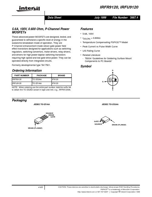
IRFR9120中文资料
S
Packaging
JEDEC TO-251AA JEDEC TO-252AA
SOURCE DRAIN GATE GATE SOURCE DRAIN (FLANGE) DRAIN (FLANGE)
4-83
CAUTION: These devices are sensitive to electrostatic discharge; follow proper ESD Handling Procedures. PSPICE™ is a trademark of MicroSim Corporation. or 407-727-9207 | Copyright © Intersil Corporation 1999
PARAMETER Source to Drain Diode Voltage (Note 2) Reverse Recovery Time Reverse Recovery Charge NOTES: 2. Pulse test: pulse width ≤ 300µs, duty cycle ≤ 2%. 3. Repetitive rating: pulse width limited by maximum junction temperature. See Transient Thermal Impedance curve (Figure 3) SYMBOL VSD trr QRR ISD = -5.6A ISD = -6.8A, dISD/dt = -100A/µs TEST CONDITIONS MIN TYP 130 0.70 MAX -6.3 150 1.4 UNITS V ns µC
oC/W oC/W
Drain to Source Breakdown Voltage Gate to Threshold Voltage Zero Gate Voltage Drain Current
HV9120资料
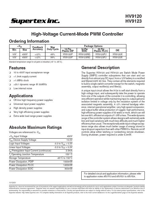
16 Pin Plastic DIP HV9120P HV9123P
Standard temperature range for all parts is industrial (-40° to +85°C).
Features
❏ 10 to 450V input acceptance range ❏ <1.3mA supply current ❏ >1.0MHz clock ❏ >20:1 dynamic range @ 500KHz ❏ Low internal noise
Notes: 1. Guaranteed by design. Not subject to production test. 2. Stray C on OSC IN pin must be ≤5pF.
3.92
4.00
4.08
25
500
nulled during trim
60
80
1.0
1.3
see fig. 1
-1.4
-2.0
0.12
0.15
see fig. 2
V
VFB Shorted to Comp
nA
VFB = 4.0V
dB MHz
Ω mA mA dB
VFB = 3.4V VFB = 4.5V
2
元器件交易网
HV9120/HV9123
Electrical Characteristics (continued)
Supertex website: . For complete liability information on all Supertex prod1ucts, refer to the most current databook or to the Legal/Disclaimer page on the Supertex website.
9120详细指标

★8路外置输出接口,每路可以输出VGA、YPbPr高清视频信号。
标清视频板卡:
★此板卡用于处理标清复合视频CVBS信号的输入、输出、画面合成、外置混音器或会讨代表机处理;板卡所包含子模块有16x32标清矩阵、8路标清画面合成器、整机控制器组成。整机控制器用于控制整机设备各个板卡的通讯、以及提供人机界面OSD、WEB、按键等多种操作设备方式。
9120
注:带★的指标项必须满足,否则投标文件技术部分得分为0
数字媒体控制主机
设备结构:
★主机采用电信级背板结构,每个功能模块采用板卡式设计,支持板卡的热插拔。主机中板卡间的工作完全独立,在应用中可根据需求配置标清视频矩阵板卡、高清矩阵板卡、音频矩阵处理板卡、集中控制板卡等多种不同功能的板卡供选择。
★8路音频信号输出,每路输出都带有音量、音调、左右平衡调节等功能,用于立体声平衡音频L/R输出,连接到功放机。
高VGA信号的输入、输出、以及高清/标清视频间转换。
★此板卡由内置16x16高清矩阵、1路升频器、1路降频器等组成;升频器可将CVBS/ YPbPr倍线转换成VGA输出,自动检测PAL/NTSC,多种不同分辨率输出,最高输出分辨率高达1280x1024;降频器用于将VGA降频转换成CVBS输出,最大支持2048x1536高分辨率输入。此板卡300MHZ带宽,可以应对1080P高清摄像头信号,以及1600x1200超高分辨率电脑信号。
★支持1路四位NETWORKS接口。
★支持1路USB接口。
★支持5路可编程输入/输出(I/O)口。
★支持8路IR红外独立发射端口。
其它:
系统电源采用AC100V~240V自适应。
912咪头芯片 原理
912咪头芯片原理912咪头芯片是一种数字信号处理器(DSP)芯片,由Texas Instruments(德州仪器)公司开发。
它广泛应用于移动通信、音频处理、图像处理和消费电子等领域。
912咪头芯片以其强大的计算能力、低功耗和高性能而闻名。
912咪头芯片采用高性能的VLIW(Very Long Instruction Word)架构,可以实现高速运算和并行处理。
其核心是一组多功能执行单元(EMU),每个EMU包含一个算术逻辑单元(ALU)和一个乘法累加器(MAC)。
这些EMU可以并行工作,实现高效的信号处理。
912咪头芯片内部包含了大量的存储器,包括程序存储器、数据存储器和寄存器文件。
程序存储器用于存储程序代码和常量数据,数据存储器用于存储运行时的数据,而寄存器文件则用于存储运算过程中的临时数据。
这些存储器具有快速的访问速度,可以满足实时信号处理的需求。
912咪头芯片还配备了丰富的外设接口,如UART、SPI、I2C、SDIO等,可以与其他外部设备进行通信。
它还支持多种中断机制,可以实现实时响应和并行处理。
912咪头芯片的软件开发主要通过集成的开发环境(IDE)实现。
Texas Instruments提供了Code Composer Studio(CCS),是一款强大的DSP软件开发工具。
它可以帮助开发者进行软件编写、调试和性能分析等工作。
此外,Texas Instruments还提供了丰富的开发文档和例程,供开发者参考和学习。
912咪头芯片在移动通信领域被广泛应用。
例如,在手机中,912咪头芯片可以用于实现音频编码和解码、语音识别和语音合成等功能。
它的低功耗和高性能使得手机可以实现更长的续航时间和更好的音频质量。
912咪头芯片还可以用于音频处理领域。
例如,在音频设备中,912咪头芯片可以用于音频解码、音效处理和声音增强等功能。
其强大的计算能力和丰富的存储器可以实现各种复杂的音频算法,提供高质量的音频效果。
- 1、下载文档前请自行甄别文档内容的完整性,平台不提供额外的编辑、内容补充、找答案等附加服务。
- 2、"仅部分预览"的文档,不可在线预览部分如存在完整性等问题,可反馈申请退款(可完整预览的文档不适用该条件!)。
- 3、如文档侵犯您的权益,请联系客服反馈,我们会尽快为您处理(人工客服工作时间:9:00-18:30)。
密级:二级保密,仅限公司内部使用MCP9120系列产品底层控制协议总表文件状态:[ ] 草稿[●] 正式发布[ ] 正在修改拟制黄伟日期2011-09-16文件编号审核段克日期2012-06-11批准日期版本号V1.7北京华夏电通科技有限公司2012年10月版本历史版本/状态作者参与者起止日期备注VER1.0 黄伟2011-06-15 首版VER1.1 黄伟2011-06-25 更新外观图,增加COS、DVC、RMS/DVS、第三方与MCP通讯命令说明,增加远程唤醒命令说明,增加音频矩阵通讯方式说明。
VER1.2 黄伟2011-06-29 音频命令表增加MIC语音激励返回码VER1.3 黄伟2011-07-08 加入高清分割网页协议VER1.4 黄伟霍成义2011-09-16 中控程序加入高清分割协议VER1.5 杨秋云2012-04-10 新增MVP0802高清分割协议VER1.6 杨秋云2012-06-11 更新音频板卡框图及MVP0802高清分割框图VER1.7 辛丽丽2012-10-15 更新mcp与第三方、RMS/DVS、DVC通讯增加数量;远程唤醒命令协议数量增加;MVP0802高清分割协议更新;目录第1章、总则 (1)1.1 背景 (1)1.2远程网络控制 (1)1.3设备外观 (1)1.4主控核心板卡框图 (2)第2章、音频底层通讯协议 (3)2.1音频矩阵框图 (3)2.2通讯控制方式 (3)2.3音频输入设置指令 (3)2.4音频输出设置指令 (6)2.5音频矩阵切换指令 (7)2.6第一路编码录制音频控制指令 (8)2.7MIC语音激励返回码 (9)2.8其它音频控制指令 (9)第3章、视频矩阵内部通讯协议 (11)3.1VGA矩阵框图 (11)3.2VGA矩阵信号切换指令 (11)3.3VIDEO矩阵框图及信号切换指令 (12)3.4视频分割指令 (13)3.5VGA转VIDEO(降频器)相关指令 (13)3.6话筒ID设置 (14)3.7设置倍线器分辨率 (14)3.8CVBS/分量转VGA多功能转换器 (14)3.9其它控制命令 (15)第4章、高清分割器通讯协议 (16)4.1高清分割器框图 (16)4.2高清分割器网页送给中控COM6的协议 (16)4.3高清分割器控制协议 (18)第5章、MIC混音器通讯协议 (34)5.1控制总体框图 (34)5.2协议格式(外置MIX1012—10路MIC) (35)5.3通讯协议 (36)第6章、MCP 网络功能概图及协议说明 (41)6.1功能 (41)6.2概要说明 (43)6.3控制命令 (43)6.4远程唤醒 (47)6.5 COS与MCP通讯 (48)6.6 MCP与编码器DVC通讯 (49)6.7 MCP与RMS/DVS通讯 (50)6.8 MCP与第三方IP设备通讯 (50)第7章、COS4.0按钮指令及说明 (51)第8章、中控控制系统指令及说明 (53)8.1中控框图 (53)8.2中控工程命令表 (54)MCP9120系列产品底层控制协议总表-1-第1章、 总则1.1 背景本文主要针对MCP9120系列产品的底层控制协议进行说明,此协议是编写中控工程、MCP 网页、远程网络控制软件、音频矩阵控制、高清分割器控制,与第三方设备做接口的基础。
1.2 远程网络控制对于远程网络控制MCP 主机,可以采用2种编程方式: 一种是直接发送此文章所列出的最底层控制协议;另一种是发中控指令。
当MCP 主机接收到网络TCP/IP 来指令后,若判断并非最底层指令,直接将此指令转发给中控PGM 去执行,此种控制方式的灵活性强,因为发一条指令可以让中控做一系列指令操作。
1.3 设备外观MCP9120形态(6U 机箱高度)1.4 主控核心板卡框图主主主主UART #1 控制指令UART #2 音频控制UART #0 PROGRA M(外接)LAN7第一层板卡RS232口(2,3脚)UART #2UART #1第一层板卡八芯音频座第三层板卡/音频矩阵卡UART #0中控板/com6解码输出cvbs (控制菜单)IIC 控制SPI EEPROM 控制三线控制:矩阵/按键更新升级更新其它I/O 控制主控核心板卡第2章、音频底层通讯协议2.1音频矩阵框图2.2通讯控制方式1、通过485总线与DM355通讯(网页控制方式);2、通过中控板外接端口RS232-5串口通讯,波特率为38400bps,8N1。
2.3音频输入设置指令功能命令格式命令解释MIC/Line 1~13 (AUDIO IN 1~13)“增益调节”MG(inputchannel),(value).a、input channel表示音频输入通道号,取值范围为1~13;b、value表示增益值大小。
例如:MG1,10.此命令表示:调节MIC/Line In 1音频输入通道的增益为10。
注意:input channel与val之间要用”,”隔开,命令结束要加”.”。
MIC/Line 1~16 “音量调节”MV(inputchannel ),(value).a、input channel表示音频输入通道号,取值范围为1~16;b、value表示要设置音量值的大小,取值范围为0~19。
例如:MV1,10.此命令表示:调节MIC/Line In 1音频输入通道的音量值为10。
注意:input channel与val之间要用”,”隔开,命令结束要加”.”。
一次性设置所有MIC/Line(1~13)为同一音量值ALLMV(value).a、value表示要设置音量值的大小,取值范围为0~19。
例如:ALLMV10.此命令表示:设置MIC1~13音频输入通道音量值全为10。
注意:命令结束要加”.”。
MIC/Line 1~16 “激励调节”MS(inputchannel ),(value).a、input channel表示音频输入通道号,取值范围为1~16;b、value表示要设置激励值的大小,取值范围为0~19。
例如:MS1,10.此命令表示:调节MIC 1输入通道的激励值为10。
注意:input channel与val之间要用”,”隔开,命令结束要加”.”。
一次性设置所有MIC/Line(1~13)为同一激励值ALLMS(value).a、value表示要设置激励值的大小,取值范围为0~19。
例如:ALLMS10.此命令表示:设置MIC1~13激励值全为10。
注意:命令结束要加”.”。
设置MIC/Line(1~16)某一输入通道静音(Mute)MMON(input channel).a、input channel表示音频输入通道号,取值范围为1~16.例如:MMON10.此命令表示:设置MIC10输入通道静音。
注意:命令结束要加”.”。
设置MIC/Line(1~16)某一输入通道静音关闭(UnMute)MMOFF(input channel).a、input channel表示音频输入通道号,取值范围为1~16.例如:MMOFF10.此命令表示:设置MIC10输入通道静音关闭。
注意:命令结束要加”.”。
打开MIC/Line 1~13 中某路MIC的“48V电源”MPON(input channel ).a、input channel表示音频输入通道号,取值范围为1~13;例如:MPON10.此命令表示:打开MIC10幻相电源。
注意:当信号源为Line时,电源应关闭(操作时,必需慎重,否则烧坏Line 信号设备)。
电源开关设置默认为关。
命令结束要加”.”。
关闭MIC/Line 1~13 中某路MIC的“48V电源”MPOFF(input channel ).a、input channel表示音频输入通道号,取值范围为1~13;例如:MPOFF10.此命令表示:关闭MIC10幻相电源。
注意:当信号源为Line时,电源应关闭(操作时,必需慎重,否则烧坏Line 信号设备)。
电源开关设置默认为关。
命令结束要加”.”。
2.4音频输出设置指令功能命令格式命令解释AUDIO OUT 1~8中某路输出端的“音量调节”AVM(output channel ),(value).a、output channel表示音频输出通道号,取值范围为1~8;b、value表示要设置音量值的大小,取值范围为0~19。
例如:AVM2,10.此命令表示:设置AUDIO OUT 2音量值为10。
注意:output channel与val之间要用”,”隔开,命令结束要加”.”。
AUDIO OUT 1~8中某路输出端的“低音调节”ABM(output channel ),(value).a、output channel表示音频输出通道号,取值范围为1~8;b、value表示要设置低音值的大小,取值范围为0~19。
例如:ABM1,10.此命令表示:设置AUDIO OUT 1低音值为10。
注意:output channel与val之间要用”,”隔开,命令结束要加”.”。
AUDIO OUT 1~8中某路输出端的“高音调节”ATM(output channel ),(value).a、output channel表示音频输出通道号,取值范围为1~8;b、value表示要设置高音值的大小,取值范围为0~19。
例如:ABM1,10.此命令表示:设置AUDIO OUT 1低音值为10。
注意:output channel与val之间要用”,”隔开,命令结束要加”.”。
打开AUDIO OUT1~8中某路输出端的“静音”AMON(output channel ).a、output channel表示音频输出通道号,取值范围为1~8。
例如:AMON1.此命令表示:设置AUDIO OUT 1静音打开。
注意:命令结束要加”.”。
关闭AUDIO OUT1~8中某路输出端的“静音”AMOFF(output channel ).a、output channel表示音频输出通道号,取值范围为1~8。
例如:AMOFF1.此命令表示:设置AUDIO OUT 1静音关闭。
注意:命令结束要加”.”。
2.5音频矩阵切换指令功能命令格式命令解释音频矩阵切换(打开某通道)ASON(input channel ),(outputchannel).a、input channel表示音频矩阵输入通道号,取值范围为1~16;b、output channel表示音频矩阵输出通道号,取值范围为1~10。
例如:ASON6,8.此命令表示:把MIC6输入通道信号切换到AUDIO OUT 8输出通道。
注意:input channel与val之间要用”,”隔开,命令结束要加”.”。
