光纤端面检验规程
裸光纤抛光和镀膜端面目检标准
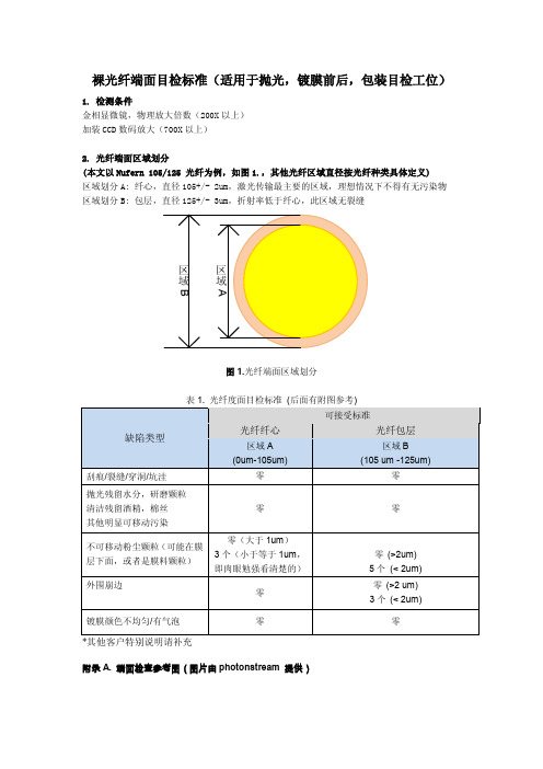
裸光纤端面目检标准(适用于抛光,镀膜前后,包装目检工位)
1. 检测条件
金相显微镜,物理放大倍数(200X以上)
加装CCD数码放大(700X以上)
2. 光纤端面区域划分
(本文以Nufern 105/125 光纤为例,如图1.,其他光纤区域直径按光纤种类具体定义)
区域划分A: 纤心,直径105+/- 2um,激光传输最主要的区域,理想情况下不得有无污染物区域划分B: 包层,直径125+/- 3um,折射率低于纤心,此区域无裂缝
图1.光纤端面区域划分
表1. 光纤度面目检标准(后面有附图参考)
附录A. 端面检查参考图(图片由photonstream 提供)
图 A.1(高反膜)好图 A.2 (增透膜) 好
图 A.3 可接受图 A.4 可接受
图 A.5 拒绝图 A.6 拒绝
刮痕,粉尘颗粒暗坑,穿洞/坑洼/焦点/污染物
图A.7拒绝图A.8 拒绝
很多颗粒污染纤芯大脏污
图 A.9 拒绝图 A.10 拒绝
液体残留+崩边镀膜层扭曲
3. 光纤镀膜端侧面检查
此区域为已经剥除环氧涂覆层的裸光纤(图 2.的fiber tip), 镀膜后,膜层有一定的厚度(50~1200nm 不等), 前端侧面会有一些镀膜材料的污染,显示斑斓色。
图2. 镀膜端光纤侧面
表2. 光纤头侧面检验标准(图3)
A.好
B.有液体污染
C.有压痕,斜面过大
图3. 光纤侧面判断标准。
光纤连接器检验技术标准

《光纤连接器检验技术标准》-------拟制:张百印一、外观检验:检验项目 检验标准备注完整性各个零部件齐全,与相应的设计、制造要求一致,加工质量符合相关技术文件要求,测试数据、标贴、条码等无误外观 各个部件须平滑、洁净、无脏污及毛刺,无伤痕和裂痕,颜色鲜亮、一致性好。
各零部件组合严密、平整,连接头与适配器的插入和拔出平顺、轻巧,卡子有力、弹性好、插拔正常。
光缆外观平滑光亮,无杂质,无破损,印字清晰,颜色与产品要求相符光缆长度长度(L ) 公差 可根据客户要求做相应修改 L ≤0.5m+0.01/-0m 0.5m<L<5m +0.05/-0m 5m ≤L ≤10m +0.1/-0m L>10m+0.2/-0m标识 视订单要求在尾套后端贴序列号或标记环或无包装包装盒上应具备:产品名称、型号、生产批次、生产日期、公司注册商标、执行标准号、环保标识、产品说明书等,包装要完整,不能有破损、挤压、变形、脏污等外观不良 可根据客户要求做相应修改二、组装性能:2.1插芯:突出长度正常,弹性良好,有明显倒角,表面无任何脏污、缺陷及其他不良。
2.2散件:各散件与适配器之间配合良好,无松脱现象,机械性能良好,有良好的活动性,表面无任何脏污、缺陷、破损、裂痕,颜色与产品要求相符,同批次产品无色差。
2.3压接:对光缆外皮及凯夫拉线的压接固定要牢固,压接金属件具有规则的压痕,无破损、弯曲,挤压光缆等不良。
三、端面标准:根据附录1《光纤连接器端面检验规范》检验。
四、插损、回损技术标准:连接头型号 FC 、SC 、LC 、ST 、MU 、E2000、D4、DIN模式 SM MM 端面规格 PC UPC APC PC IL(dB) ≤0.3 ≤0.2 ≤0.3 ≤0.3 RL(dB) ≥45≥50≥60 ≥35 其他型号 MT-RJ 、MPOIL(dB) ≤0.7 / ≤0.7 ≤0.5 RL(dB)≥30/≥50≥25五、端面几何形状(3D )标准:项目PC、UPC APCSC、FC、ST、E2000、D4、DINLC、MUSC、FC、E2000LC、MU SM MM SM MM SM SM曲率半径(mm) 10-25 7-20 5-12顶点偏移(μm)≤50≤30光纤凹陷(nm)±100角度偏差(°) 0 8±0.3键角偏差(°) 0 ±0.5光纤直径(μm)123-135六、合格品标识:合格产品标识包括:出厂编号(每个产品对应唯一的出厂编号,由生产任务计划号加流水号组成)、型号规格、条码标签(根据客户要求可选)、产品说明书(根据客户要求可选)、3D 报告(根据客户要求可选)、环保标识(根据客户要求可选)、插/回损测试数据等。
光纤端面的检测方法及步骤
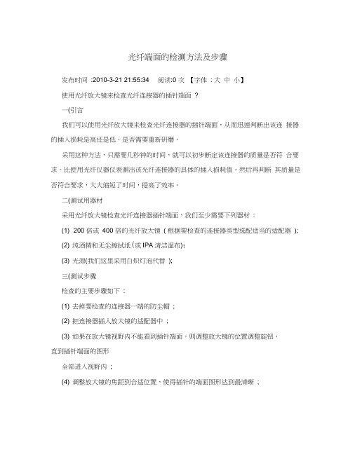
光纤端面的检测方法及步骤发布时间:2010-3-21 21:55:34 阅读:0 次【字体: 大中小】使用光纤放大镜来检查光纤连接器的插针端面?一(引言我们可以使用光纤放大镜来检查光纤连接器的插针端面,从而迅速判断出该连接器的插入损耗是高还是低,是否需要重新研磨。
采用这种方法,只需要几秒钟的时间,就可以初步断定该连接器的质量是否符合要求。
比使用光纤仪器仪表测出该光纤连接器的具体的插入损耗值,然后再判断其质量是否符合要求,大大缩短了时间,提高了效率。
二(测试用器材采用光纤放大镜检查光纤连接器插针端面,我们至少需要下列器材:(1) 200 倍或400 倍的光纤放大镜( 根据要检查的连接器类型选配适当的适配器);(2) 纯酒精和无尘擦拭纸(或IPA清洁湿布);(3) 光源(我们这里采用白炽灯泡代替);三(测试步骤检查的主要步骤如下:(1) 去掉要检查的连接器一端的防尘帽;(2) 把连接器插入放大镜的适配器中;(3) 如果在放大镜视野内不能看到插针端面,则调整放大镜的位置调整旋钮,直到插针端面的图形全部进入视野内;(4) 调整放大镜的焦距到合适位置,使得插针的端面图形达到最清晰;(5) 检查插针端面,对于研磨效果很好的连接器。
其端面应该是圆形的,很光洁,光纤芯与插针的端面齐平,并呈现同心圆环形状; 如果端面有灰尘(或瑕疵),则用IPA 清洁湿布或无尘擦拭纸沾纯酒精擦拭,直到表面没有灰尘(或可以看到清晰的瑕疵);(6) 去掉连接器另一端的防尘帽,并使该端的插针对准白炽灯泡,在我们刚刚检查过的连接器端可以看到光亮,否则,该连接器的光缆有折断的地方;(7) 重复上述步骤,再检查一次,将会看到纤芯非常亮的插针端面图,有可能发现较小的瑕疵;(8) 调换连接器的两端,重复上述步骤,检查另外一个端面;(9) 用标签标出存在问题的连接器端,采用适当的方法,或研磨或重新装配连接头,然后重复上述步骤进行检查。
光纤连接器端面的检测与清洁方法

光纤连接器端面的检测与清洁方法作为最便捷的光纤接续方式,光纤活动连接器已广泛应用于光通信布线网络,光通信设备及测试设备中。
通常情况下,光纤连接器都是以光纤跳线、预端接光缆等型式应用到实际的工程项目中,这些跳线连接器在网络的安装、调试及维护过程中,往往会经历多次的插拔过程。
而在这一过程中,经常会由于操作人员不注意对连接器端面的防护,导致光纤端面受到污染,从而影响到光链路传输性能的下降,增加连接器的插入损耗(Insertion loss)和降低连接器的回波损耗(Return loss),严重时甚至会造成整个链路的瘫痪。
因此,要正确认识光纤连接器端面检测与清洁的重要性,在日常的操作及维护中,应该严格执行操作规范,确保光纤跳线端面的清洁度。
如果光纤端面被污染了,就要按规范的程序进行清理。
常见的光纤连接器端面污垢检测的方法有目测检查和仪器检查两种:●目测检查一般情况下最普通的检查端面污垢做法是:断开设备后拿起光纤连接器端面正对光线,首先查看是否的明显的尘埃及污垢,然后通过观察端面对光线的折射是否明亮来检测端面是否洁净和平滑,如果端面对光线的反射为平滑明亮则认为是比较洁净的,如果端面对光线的反射不太明亮和不够平滑,很有可能是有污垢存在或者端面上有灰尘,这样的端面将严重影响光传输的质量。
当然借助专业仪器对端面进行检查能更加全面地了解端面上的细节问题。
●仪器检查目前针对光纤端面的检查工具仪器比较多,其中光纤显微镜是使用最广泛的专业检查仪器。
一般情况下用于多模的光纤显微镜显示倍率为200倍,而用于单模的光纤显微镜显示倍率为400倍。
更为先进的光纤显微镜不但可以在两种倍率间自由切换,更可以通过LCD屏幕显示光纤端面情况,从而不需要断开设备检测光纤端面,还避免了眼睛受到激光损伤的风险。
以下是通过仪器观察到的几种典型端面污染情况。
见图1、图2、图3、图4:一般对于数量多、重复性高的端面检测。
如光纤跳线,光模块的生产厂家以及相关的检测试验室,采用固定式的光纤端面显微镜。
光纤连接器端面

图像卡 光源
控制卡 PZT
控制回路
CCD
图 3. 光纤连接器端面检测干涉仪系统概要
结像镜
半透镜
物镜
连接器
图 4 干涉条纹图像
图 5 3D 表面形状
图 6 等高线图
(2)载物台的倾斜调整 载物台的倾斜调整是一项关键技术。如果载物台的倾斜调整精度不高,将极大地影响球面顶点偏心,
APC 角度及定位键角度的测量精度。图 7 为倾斜调整和球面顶点偏心测量精度的关系概要。如图 7(a)所 示,当载物台倾斜调整完整时,干涉仪光学系统的光轴将与被测定光纤连接器的插芯的中心轴平行。此时, 旋转被测定光纤连接器时,光纤连接器端面的球面顶点(环形干涉条纹的中心如 A 点或 B 点)将绕光纤的 中心 O 点旋转,构成一个以 O 点为中心的圆。測定的頂点偏芯值 OA 或 OB 将与実際的頂点偏芯相同。也就 是说,无论旋转光纤连接器到什么角度,測定的頂点偏芯值的变化将不会太大。相反,如图 7(b)所示, 当载物台倾斜调整不完整时,干涉仪光学系统的光轴将会与被测定光纤连接器的插芯的中心轴交叉成一个 角度。此时,旋转被测定光纤连接器时,光纤连接器端面的球面顶点(环形干涉条纹的中心如 A 点,B 点, C 点或 D 点)会绕一个与光纤的中心 O 不相同的中心 O*旋转,构成一个以 O*为中心的圆。显然,在不同位 置測量的頂点偏芯值 OA,OB 或 OC 将与実際的頂点偏芯 OD 不相同。也就是说,旋转光纤连接器后,測定 的頂点偏芯值将会有很大的变化。从这个现象也可以得到一个检验载物台倾斜调整是否完整的方法。即, 旋转光纤连接器,依次測定頂点偏芯值,如果測定的頂点偏芯值变化不大,则载物台倾斜调整是完整的。 反之,则载物台倾斜调整是不完整的。为了提高载物台倾斜的调整精度,我们开发了一种高精度,操作简 单的载物台倾斜调整技术(已申请多国专利)7,8,可以达到大大高于一般调整方法的调整精度。
mpo 端面iec检验标准

MPO(Multi-fiber Push-on)端面是一种用于光纤连接的插芯式端面。
IEC(International Electrotechnical Commission,国际电工委员会)针对MPO 端面的检验标准主要为IEC 61754-27:2017《Optical fibres - Fibre optic connectors - Part 27: Test methods for MPO connectors》。
IEC 61754-27:2017 标准中,对MPO 端面的检验方法和要求进行了详细规定。
主要包括以下几个方面:
1. 外观检查:检查连接器端面的外观,确保无明显的损伤、划痕或污渍。
2. 插入损耗:测量光纤连接器在插入和拔出过程中的损耗,评估连接器的性能。
3. 回损:测量连接器在一定条件下,从插拔循环过程中的损耗。
4. 反射系数:测量连接器端面对光的反射系数,以评估连接器的反射性能。
5. 接触电阻:测量连接器端面与光纤的接触电阻,以评估连接器的导通性能。
6. 温度稳定性:测试连接器在不同温度下的性能变化,评估其温度稳定性。
7. 插拔次数:测试连接器的插拔寿命,评估其耐用性。
8. 光学性能:测量连接器在一定条件下的光学性能,包括损耗、色散等。
9. 机械性能:测试连接器的机械强度、振动性能等。
10. 环境性能:评估连接器在不同环境条件下的性能,如湿度、盐雾等。
光纤端面检测

光纤端面检验资料用光纤放大镜检查光纤连接器端面 1﹑目的1.1 介绍采用光纤放大镜检查光纤连接器的方法﹐并对各种检查结果作出分析,提出相应的改进措施。
1.2 使用光纤放大镜来检查光纤连接器的插针端面是否符合产品等级要求。
2﹑检测用器材及物料2.1 200倍或400倍的光纤放大器(根据检验规范确定)。
2.2 根据要检查的连接器类型选配适当的适配器。
2.3 纯酒精(酒精含量不低于98﹪)。
2.4 无尘纸(无毛软纸)。
2.5 光源3﹑操作重点3.1 如果在放大镜视野内不能看到插针端面,则调整放大镜的位置调整旋钮,直到插针端面的图形全部进入视野内并使得插针的端面图形达到最清晰。
3.1.1 插针端面调整到最清晰状态后应最少观察端面1秒钟以上,以便有足够的时间对于所看到的图像进行分析,防止出现漏看现象。
当端面上有异常现象时一定要进行确认,不可盲目的流向下工序。
纤芯(ø62.5μ) 包层(ø125μ) 纤芯(ø9μ) 包层(ø125μ)3.2 检查插针端面,对于研磨效果很好的连接器。
其端面应该是圆形的,很光洁,光纤芯与插针的端面齐平,并呈现同心圆环形状;3.2.1 在连接头放入到检测设备之前应先在干的无尘纸上擦拭端面,如果端面有污物(或斑点),则用无尘纸沾纯酒精擦拭,直到表面没有污物(或可以看到清晰的斑点)。
不允许一开始就采用沾有酒精的无尘纸擦拭端面。
3.2.1 擦拭端面时应注意选用无尘纸上没有擦拭过的干净区域﹐擦拭的时候应该以插芯端面垂直于无尘纸朝一个方向划过去约10mm左右﹐力度不可太大﹐绝对不允许在同一地点来回擦拭,或是作曲线、折线运动。
3.2.2 当有难以去除的污渍时可在无尘纸的小块区域内沾上少许酒精再擦拭插芯端面﹐在用酒精擦拭过后一定要在干的无尘纸上擦拭后再看端面。
3.2.3 切记不可用力压住连接头进行擦拭。
3.2.4 连接头插入适配器时要用手拿住连接头的尾部,不可只拿住光缆将连接头送入到适配器中,以免当连接头在适配器内受力时尾部产生光纤的折损。
光纤端面等级验收标准

光纤端面等级验收标准
光纤端面等级验收标准是光通信行业中的一项重要标准,用于评估光纤连接器端面表面质量的好坏。
以下是光纤端面等级验收标准的主要内容:
1. UPC(Ultra Physical Contact)等级:UPC系列连接器端面
要求光纤端面碳化度达到0.5μm以下,表面光滑度要求较高,光纤连接时能提供较好的插入和回拉力,使多模光纤的回波损耗在0.3dB以下,单模光纤的回波损耗在0.2dB以下。
2. APC(Angled Physical Contact)等级:APC系列连接器端
面要求光纤端面采用8度抛光,形成较小的倾斜角度,避免反射损失。
APC连接器端面较适用于单模光纤系统,连接器端
面的反射损耗应在60dB以上。
3. PC(Physical Contact)等级:PC系列连接器端面光纤端面
碳化度达到0.5 ~ 1.5μm之间,表面光滑度较好,插入和回拉
力较大,适用于多模光纤传输系统,连接器端面的回波损耗应在0.5dB以下。
根据实际场景和应用需求,选择合适的光纤连接器端面等级,能够保证信号传输的质量和速度。
光缆施工质量检验评定规程范例

光缆施工质量检验评定规程范例《最全的光缆施工验收标准要求规范》光缆是整个弱电结合布线的重要组成,也是传输信号的主干线路,没有光缆,就无法传输强大数据业务,光缆在弱电重要性可想而知。
今天说下光缆线路工程的验收标准,在施工中一定要注意,按照光缆验收标准来施工,便于后期检查验收,达到交会付要求,具体验收细节如下。
一、机房端1、入局光缆在进出孔、ODF架端要挂牌编号,标牌与竣工资料相符;2、进/出局光缆和用户光缆应全部检查光缆的预留长度、盘放安置、保护措施及成端质量。
3、进/出局光缆内的金属构件在终端处要接地;4、入局光缆进出孔要用防火泥堵塞;三、线路架空杆路:1、架空光缆抽查的长度应不小于光缆全长的10%,沿线检查杆路与其他设施间距(含垂直、水平)、光缆及接头安装质量、预留光缆盘放、与其他线路交越、靠近供电线保护措施。
2、电杆应按设计规定的杆距立杆。
一般情况下,市区光缆线路的杆距为35~40m,郊区明线线路的杆距为45~50m。
因地形特殊情况距离不要超过65米。
3、竖立电杆应达到下列标准:直线线路的电杆位置应在线路路由的中心线上,电杆中心线与路由中心线的左右偏差应不大于50㎜,电杆本身应上下垂直。
角杆应在线路转角点内移,水泥电杆的内移值为100~150㎜,木杆的内移值为200~400㎜,因地形限制或装撑木的角杆可不内移。
终端杆竖立后应向拉线侧倾斜100~200㎜。
4、拉线装置应符合设计要求,拉线应采用镀锌钢绞线,拉线扎固方式以设计的材料为准进行实施。
5、靠近高压电力设施及热闹市区的拉线,应根据设计规定加装绝缘子。
绝缘子朝上的拉线上部长度应适量,但绝缘子距地面的垂直距离应在2m以上,拉线绝缘子的扎固规格应符合设计要求。
人行道上的拉线宜以竹筒或木桩保护。
6、拉线上把与水泥电杆应用抱箍法结合起来;与木杆可用捆缚法。
7、号杆应按设计规定进行安装。
号杆的字或牌的高度,最末一个字或杆号牌下边缘应距地面2.5m,杆号应面向街道。
光纤端面的检验
400X
不可擦除 污物、麻 点、斑点
400X
宽度≤10μ m的允 亮斑直径 许 ≤10μ m或胶 直径≤10μ m的允 圈宽度≤5μ m 许
400X
1µ m 2µ m 5µ m 8µ m 10µ m
1µ m 2µ m 5µ m 8µ m 10µ m
光纤包层Cladding (125μm dia.)
陶瓷柱面Ferrule (400μm dia.)
为什么端面的清洁很重要?
1、连接器的正常连接
正常连接
为什么端面的清洁很重要?
2、插针柱面带有污渍对连接器的耦合有很大的影响,它会 影响到陶瓷套筒的清洁,可能造成连接过程中出现错位
柱面脏污情况下的连接
连接器端面的检验
光迅公司质保部 2010-02-25
连接器端面的检验
为什么端面的清洁很重要? 端面的清洁方法
端面检验的标准
为什么端面的清洁很重要?
光纤在连接器的陶瓷插针中,连接器插入法兰的陶瓷套筒, 使两端的光纤准确对接,保证光在光纤中传输。
纤芯 Core (10μm dia.)
1/4包层 1/4Cladding (30μm dia.)
1µ m 2µ m 5µ m 8µ m 10µ m
说明:圆圈代表相应尺寸的残留物、麻点、 斑点大小;黑色线条宽度代表划痕的宽度
端面的检验标准
端面检查时的典型例样:
THE END!
1、插针柱面的清洁方法 左手捏住连接头,右手拿蘸有酒精的擦拭纸附着在陶瓷插针 柱面上,然后右手的食指和拇指通过擦拭纸捏住陶瓷插针柱 面向外旋转。将插针柱面上的污迹带到擦拭纸和插针的顶端
端面的清洁方法
如何检查和清洁光纤端面
e tnl i a ye 布gcp b全 cd i 略a 线 攻 n o E
如何检查和清洁光纤端面
文 f 国 福 禄 克 公 司 尹 美 岗 【 摘 要 】 个 直 径 1 办 公 室 灰 尘就 能 将 9u 的 单 模 光 纤 挡 住 ,严 重 影 响 光 信 号 的传 输 效 率 甚 至 一 0u m m 中 断 数 据 信 号 的 传 输 。 光 纤 端 面 检 查 和 清 洁 是 光 纤 接 入 前 的 一 个 必 要 步 骤 。 另一 方 面 , 由于 短 距 离 低
成 玻 璃 晶 体 破 碎 或 者 存 在 裂 纹 ,有 时 候 这 种 缺 陷是在 磨 制 镜 面 前截 断 光 纤 时就 已经 造成 了 玻 璃 晶 体 的 损 伤 。 通 常 ,这 类 制 造 缺 陷 可 以用光纤 端面显 微镜 直接观 察到 。 光纤 插 头 的实 际结构 很像 一 种套 筒 结构 , 套 筒 的 中 间就 是 光 纤 ,外 周 多 为用 于 固定 光 纤 的 耐 磨 精 密 陶 瓷 或 塑 料 。 光 纤 和 耐 磨 精 密
心 被 认 为 是 对齐 的。 由于 绝 对 的偏 心 误 差是
不 可 避 免 的 ,工 程 安 装 允 许 存 在 一 定 误 差 , 只要 不 超标 ,造 成 的影 响就 可 以忽 略。轴 心
对 齐 偏 差 会 增 加 损耗 ,在 低 速 光 纤 链 路 中 ,
个 别 连 接 器 虽 然 质 量 很 差 ,但 只 要 链 路 中 多
速光纤链 路对光 纤端面破 损和脏 污等现象并不 是很敏 感 ,这类潜 在 问题 多数是在 更换高速 光模块或设
备 时 才 凸 显 出来 , 因 为 高 速 光 纤 链 路 对 连 接 器 的 端 面 连 接 质 量 更 敏 感 一 些 ( 耗 / 波 / 损 回 色散 ) 随着 。
VIAVI Solutions 光纤连接器端面质量检查最佳实践指南说明书

Executive SummaryIt is widely known in the fiber optic industry that scratches, defects, and dirt on fiber optic connector end faces negatively impact network performance. As bandwidth requirements continue to grow and fiber penetrates further into the network, dirty and damaged optical connectors increasingly impact the network. If dirty and damaged end faces are not dealt with systematically, these defects can degrade network performance and eventually take down an entire link.In the effort to guarantee a common level of performance from the connector, the International Electrotechnical Commission (IEC) created Standard 61300-3-35, which specifies pass/fail requirementsfor end face quality inspection before connection. Designed to be a common reference of product quality, use of the IEC Standard supports product quality throughout the entire fiber optic life cycle, but only when compliance to the standard occurs at each stage. In response, current best practices recommend systematic proactive inspection of every fiber optic connector end face before connection. While current research shows that this practice is eliminating the installation of contaminated fibers and improving network performance, the uncontrollable variables of technician eyesight and expertise, ambient lighting, and display conditions keep manual inspectionand analysis from being a 100-percent reliable and repeatable method of assuring IEC compliance. In addition, because manual inspection does not create a record of the inspection process, certification of quality at the point of installation is not practical.Because compliance to the IEC Standard is the onlyway to achieve the promise of today’s fiber-rich, high-connectivity networks, this white paper proposesthe automation of the inspection process throughthe addition of analysis software programmed to the Standard’s pass/fail criteria to the practice of systematic proactive inspection.Automation of the systematic proactive inspection process using software programmed to the IEC Standard eliminates the variables associated with manual inspection, provides a documentable record of the quality of the connector end face at the point of installation, and provides a 100-percent repeatable and reliable process.White PaperAchieving IEC Standard Compliance for Fiber Optic Connector Quality through Automation of the Systematic Proactive End Face Inspection ProcessCombined, these benefits make automated end face inspection the most effective method available to assure and certify compliance to the IEC Standard throughout the fiber optic product life cycle, and achieve the promise of next-generation networks.IEC Standard 61300-3-35IEC Standard 61300-3-35 is a global common set of requirements for fiber optic connector end face quality designed to guarantee insertion loss and return loss performance. The Standard contains pass/fail requirements for inspection and analysis of the end face of an optical connector, specifying separate criteria for different types of connections (for example, SM-PC, SM-UPC, SM-APC, MM, and multi-fiber connectors). For more detail onthe Standard, copies of the copyrighted document are available for purchase at by searching for “61300-3-35”.These criteria are designed to guarantee a common level of performance in an increasingly difficult environment where fiber is penetrating deeper into the network and being handled by more technicians, many of whom may be unfamiliar with the criticality of fiber optical connector end face quality or possess the experience and technical knowledge required to properly assess it.Figure 1. Fiber Optic Product Life CycleThe standard is designed to be used as a common quality reference between supplier and customer, and between work groups in several ways:y As a requirement from the customer to the supplier (for example, integrator to component supplier or operator to contractor)y As a guarantee of product quality and performance from the supplier to the customer (for example, manufacturer to customer, contractor to network owner, or between work groups within an organization)y As a guarantee of network quality and performance within an organizationAs more stages in the fiber optic product life cycle, shown in Figure 1, are outsourced to disparate vendors, the standard takes on renewed importance in ensuring the optimized performance of today’s fiber-dense networks.The Development of the IEC StandardThe quality values used in the IEC standard are the result of years of extensive testing of scratched, damaged,or dirty optical connectors conducted by a coalition of industry experts including component suppliers, contract manufacturers, network equipment vendors, test equipment vendors, and service providers. This work has been published previously in a number of papers as noted in the References section of this paper.Understanding the variables and limitations of manual visual inspection, fiber optic test and measurement manufacturer VIAVI contributed its automated objective inspection and analysis software FiberChek2™, as illustrated in Figure 2, to the IEC for use in the development of the 61300-3-35 visual inspection standard. Automating the pass/fail process using research-based parameters extracted from testing conducted by the aforementioned industry coalition provided the IEC with a repeatable standard of quality that would guarantee a common level of performance, creating a positive impact on both product and network performance.More than 8 years of testing on a constantly expanding database of fibers and fiber devices (for example, SM, MM, Ribbon, E2000, SFP/XFP, Bend-insensitive fibers, Lenses, and other interfaces), combined with widespread use in the industry by component manufacturers, integrators/CMs, OEMs, third-party installers, and service providers, makes the VIAVI software program the only proven automated objective inspection software program that assures compliance to the IEC standard at every step of the fiber optic life cycle.Testament to this is the fact that this software program is currently used by three of the top five U.S. cable assembly manufacturers, along with six of the largest optical component manufacturers, five of the largest network equipment vendors, and five of the top Network Service Providers (NSPs) in the world, making VIAVI FiberChek2 software the current worldwide industry standard for automated objective fiber optic connector end face inspection.Figure 2. Example of the Proven Inspection and Analysis Software Program FiberChek2 from VIAVIThe criteria in the IEC Standard requires the user to know the exact location and size of surface defects (for example, scratches, pits, and debris) on the fiber optic connector end face. As a result, it is only through the use of automated inspection and analysis software that compliance to the IEC Standard (or customer specification) can be tested and certified.The combination of common requirements (the IEC Standard) and automated inspection and analysis (FiberChek2) have measurably impacted product quality through the supply chain. This is providing improved repeatability and stability of inspection analysis throughout the fiber optic product life cycle, ensuring consistent product performance regardless of the number and expertise of vendors and technicians involved in the manufacture, installation, and network administration processes.Proactive Inspection Model: Step One Toward Achieving IEC ComplianceDespite its role in the development of the IEC Standard and usage by industry leaders, automated inspection and analysis software is not yet in widespread use across the fiber optic industry. In an effort to enable compliance to the Standard even when using manual visual inspection equipment alone, IEC and industry leaders are supporting the promotion of fiber handling best practices. An example of one such educational effort is the proactive inspection model developed and promoted by fiber optic test equipment manufacturer VIAVI, “Inspect Before You Connect” (IBYC), as illustrated in Figure 3.The simple four-step IBYC model, which supports and is mandated by the IEC Standard, effectively guides technicians of varying levels of expertise in the proper implementation of systematic proactive inspection. y Step 1 Inspect: Use the microscope to inspect the fiber. If the fiber is dirty , go to Step 2. If the fiber is clean, go to Step 4.y Step 2 Clean: If the fiber is dirty , use a cleaning tool to clean the fiber end face.y Step 3 Inspect: Use the microscope to re-inspect and confirm the fiber is clean. If the fiber is still dirty , go back to Step 2. If the fiber is clean, go to Step 4.y Step 4 Connect: If both the male and female connectors are clean, they are ready to connect.Consistent use of the IBYC model ensures that proactive inspection is performed correctly every time and that fiber optic end faces are clean prior to mating connectors, eliminating the installation of dirty or damaged fibers into the network and optimizing network performance. As a result, IBYC has been incorporated intomanufacturing procedures for the majority of the world’s leading organizations using fiber, increasing knowledge of this process and helping it become routine practice around the world.Automated Inspection and Analysis: Achieving and Certifying IEC ComplianceEven with the aid of the IBYC model, manual inspection using only a video microscope can be difficult depending on the technician’s expertise and can result in variable connector quality and network performance. Reliant on technician eyesight and expertise along with variable display settings and ambient lighting, manual inspection and analysis is not 100 percent reliable, repeatable, or certifiable. Because it produces no visual record of the end face condition in the manual inspection process, certifying compliance at the point of installation through images or reporting is both unreliable and impractical, as Figure 4a shows.To ensure IEC compliance is achieved, automated inspection of fiber optic connector end faces using inspection and analysis software built on the IEC Standard’s pass/fail criteria is the most effective method available. With it technicians of all skill levels can effectively accomplish both compliance and certification through images andreports, as Figure 4b shows.PASSFigure 4b. Automated Inspection gives technicians a pass or fail result.Figure 4a. Manual Inspection requires technicians to judge whether the connector complies with the IEC Standard.Using the software, automated inspection and analysis can produce a visual record of the end face condition as shown in Figure 5, which can be used in reports and archived for future reference.)As a result, automated inspection and analysis presents several clear advantages over subjective inspection:y Eliminates variation in resultsy Certifies and records product quality at time of inspectionFigure 5. Automated inspection enables the technician to certify compliance to the standard byproducing a date stamped test report.y Enables technicians of all skill levels to certify quality reliably and systematicallyy Makes advanced pass/fail criteria simple to usey Improves product and network performance and yieldsUsing a fiber optic inspection and analysis software program that is preloaded with the IEC Standard specifications, such as VIAVI FiberChek2 software, any technician can effectively:y Inspect and certify compliance with IEC 61300-3-35 or other customer-specified standards at every stage of the fiber optic product life cycle at the push of a buttony Implement simple pass/fail acceptance testing; no skill in quality judgment is necessaryy Generate detailed analysis reports that can be archivedConclusion: Business Impact of Automated End Face AnalysisThe combination of common requirements (the IEC Standard) and automated fiber optic inspection and analysis software (FiberChek2) has positively impacted product quality across the supply chain. The business impacts of reliable, repeatable automated fiber optic connector inspection and certification include:y Insured and repeatable product quality through the quantification of connector end face condition at installationy Assurance of customer satisfaction and supplier protection through the reliable documentation of connector end face qualityy Competitive advantage for component and system vendors, and for installation contractors who can cost-effectively document end face qualityy A common, repeatable system provides correlation through the supply chainy Easy deployment of custom requirements analysisCombined, these benefits make automated end face inspection the most effective method available to assure and certify compliance to the IEC Standard throughout the fiber optic product life cycle, and achieve the promise of next-generation networks.© 2021 VIAVI Solutions Inc. Product specifications and descriptions in this document are subject to change without notice.Patented as described at /patents iecinspect-wp-fit-tm-ae 30168245 900 1010C ontact Us +1 844 GO VIAVI (+1 844 468 4284)To reach the VIAVI office nearest you, visit /contact VIAVI Solutions References1. “Qualification of Scattering from Fiber Surface Irregularities,” Journal of Lightwave T echnology , V .20, N 3, April 2002,pp. 634−637.2. “Optical Connector Contamination/Scratches and its Influence on Optical Signal Performance,” Journal of SMTA, V .16, Issue 3, 2003, pp. 40−49.3. “At the Core: How Scratches, Dust, and Fingerprints Affect Optical Signal Performance,” Connector Specifier, January2004, pp. 10−11.4. “Degradation of Optical Performance of Fiber Optics Connectors in a Manufacturing Environment,” Proceedings ofAPEX2004, Anaheim, California, February 19−Feb 26, 2004, pp. PS-08-1-PS-08-4.5. “Cleaning Standard for Fiber Optics Connectors Promises to Save Time and Money”, Photonics Spectra, June 2004,pp. 66−68.6. “Analysis on the effects of fiber end face scratches on return loss performance of optical fiber connectors”, Journalof Lightwave T echnology , V .22, N 12, December 2004, pp. 2749−2754.7. “Development of Cleanliness Specification for Single-Mode Connectors,” Proceedings of APEX2005, Anaheim,California, February 21−26, 2005, pp. S04-3-1, 16.8. “Keeping it clean: A cleanliness specification for single-mode connectors,” Connector Specifier, August 2005, pp.8−10.9. “Contamination Influence on Receptacle T ype Optical Data Links,” Photonics North, 2005, T oronto, Canada,September 2005.10. “Development of Cleanliness Specifications for 2.5 mm and 1.25 mm ferrules Single-Mode Connectors,” Proceedingsof OFC/NFOEC, Anaheim, California, March 5−10, 2006.11. “Standardizing cleanliness for fiber optic connectors cuts costs, improves quality ,” Global SMT & Packaging, June/July 2006, pp. 10−12.12. “Accumulation of Particles Near the Core during Repetitive Fiber Connector Matings and De-matings,” Proceedingsof OFC/NFOEC2007, Anaheim, CA, March 25−29, 2007, NThA6, pp.1−11.13. “Development of Cleanliness Specifications for Single-Mode, Angled Physical Contact MT Connectors,” Proceedingof OFC/NFOEC2008, San Diego, February 24−28, 2008, NThC1, pp. 1−10.14. “Correlation Study between Contamination and Signal Degradation in Single-Mode APC Connectors,” Proc. SPIE, Vol.7386, 73861W (2009); doi:10.1117/12.837545.。
光纤端面检查与清洁
深圳亿天龙科技发展有限公司
光网络维护新使命——光纤端面检查与清洁
光纤传输网络承载业务的IP化、宽带化和多样化等特征,必将对光传输网络的承载能力和质量提出更高更新的要求。
光纤连接器作为光网络中最基本也是用量最大的光无源器件,在网络系统中起着举足轻重的作用,由于连接器端面是系统中唯一裸露在外的地方,因此它的质量优劣变化,将直接影响着承载光信号传输的网络性能和质量,是网络产生数据误码、延时抖动、色散漂移等软性故障现象的关键所在,是效率低下的网络长期处于亚健康的主要原因。
由于光纤连接器(指跳线和不带功能模块的尾纤)价值低廉、光纤端面难于观察以及链路上不能轻易拔下等原因,很多维护人员往往忽略了对它的检查和有效的清理,使得端面上的缺陷越来越严重,造成网络从运行开始一直不停地出现各种软性故障,各种指标长期严重超标。
所以借助专用工人来彻底检查和清理这些低劣的光纤端面,以清除和减少故障现象,是光网络高品质完成高速度、大容量承载信息传输的首要任务,是势在必行的新使命。
FVO-600A系列光纤端面显微镜和EDV-136光纤端面电动清洁器及端面修复专用工具,正是这一新趋势、新形势下的必然产物,它是未来光网络维护保养的必备工具,甚至是不可缺少、唯一能解决问题的专用维护工具。
检查和保养光纤端面,将事后维护转变成事前维护,未知维护转变为预知维护,临时抢修转变成计划性维护,是提高网络传输质量、保证高速网络运行效益和运行安全革命性的维护新措施和最佳解决方案。
光纤验收说明

光纤验收说明随着信息化建设的不断深入,网络设备已经广泛地应用在各个行业之中,尤其是长飞光纤的应用,已经成为现代通信的标志性建筑。
光纤不但在宽带接入、用户网、局域网、城域网等领域得到广泛应用,而且在电力、交通、军事、广电、金融、水利、医疗、石油化工等行业也得到了广泛应用。
现代社会越来越快的发展使人们时不我待,光纤的特性正好满足了人们要求信息传递快速的需要,因此它的优势越来越被用户所认可。
然而安装完毕的光纤如何验收呢?这是我们今天要讨论的问题。
众所周知,光纤本身就是一条玻璃纤维增强材料,它非常脆弱,不仅对其安装施工的过程要求很高,而且对后期的维护保养也有较高的要求。
那么对于我们验收人员来说,在进行验收的时候就一定要严格按照国家规定的标准来进行。
一、预验光时,必须使用预验收仪进行测试。
二、对光纤端面的清洁程度进行检查,如果发现有灰尘或污渍,必须使用专用工具进行清理。
三、在测试过程中,需要使用光源进行照射,从光纤的一端开始,逐段进行检查,一旦发现故障或断点,就必须立即标记出来,以便后续的维修工作。
四、验收人员必须仔细检查光纤的接头是否牢固可靠,是否存在接触不良或断裂等现象。
五、根据光纤的使用范围,检查其衰减情况是否符合要求。
六、最后,验收人员应对光纤的色散性能进行检查,这是衡量光纤质量的重要指标之一。
总之,对于光纤的验收是一项相当重要的工作,因为它不仅关系到整个网络系统的运行效率,而且还直接影响到用户可以使用的带宽大小和信号质量。
因此,我们在进行光纤验收的时候必须要认真细致、严格科学,确保光纤的质量和性能能够达到预期的目标。
同时,我们也要根据具体的使用环境和需求来选择不同类型的光纤产品,以保障网络系统的稳定运行和用户的满意度。
光纤端面等级验收标准
宽度不超过1μ的划痕﹑缺陷,1μ胶环可接受(特殊情况2μ也可),黑色胶环长4μ允许有三处,无其它任何缺陷。
针孔﹑缺口超过3μ视为缺陷(未触及插芯孔或光纤边缘则直径超过了3μ针孔缺口可接受如果未引起表面粗糙小于2μ可不考虑),不允许有裂纹。
B
不允许有任何缺陷,400倍检查。
可允许有1条宽度1μ划痕(白色)长度不限,无其它任何缺陷。
E
不允许有任何黑色划痕﹑斑点等其它缺陷。光滑,洁净无其它任何污染物。允许划痕过纤芯,但不能超过总数量的10%。过程200倍﹑出货200倍检查
限定范围内允许有1u网状划痕(白色)长度﹑数量不限,无其它任何缺陷。
1μ划痕可接受数量不限,2μ缺陷可接受,胶环可接受,黑色胶环长接受,允许光纤边缘有1μ缺口4处,无其它任何缺陷。
1μ划痕可接受,1μ缺陷可接受,1μ胶环可接受(特殊情况2μ也可),6μ长黑色胶环允许有三处,无其它任何缺陷。
针孔﹑缺口超过5μ视为缺陷(未触及插芯孔或光纤边缘则直径超过了5μ针孔缺口可接受如果未引起表面粗糙小于2μ可不考虑),不允许有裂纹。
C
不允许有任何缺陷,过程400倍检查,出货200倍检查
可允许有2条宽度1μ划痕(白色)长度不限,无其它任何缺陷。
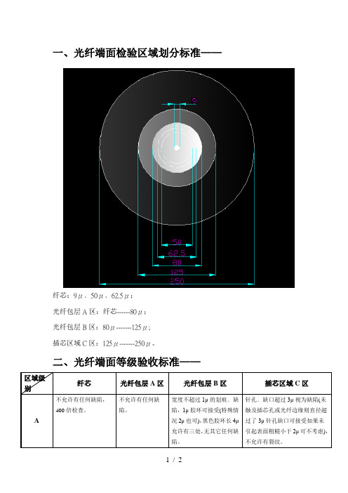
一、光纤端面检验区域划分标准——
纤芯:9μ﹑50μ﹑62.5μ;
光纤包层A区:纤芯------80μ;
光纤包层B区:80μ-------125μ;
插芯区域C区:125μ----Байду номын сангаас--250μ。
二、光纤端面等级验收标准——
区域级别
纤芯
光纤包层A区
光纤包层B区
插芯区域C区
A
不允许有任何缺陷,400倍检查。
单模光纤检验规范
管理体系文件
文件名称:G652D单模光纤检验规范
文件编号:
版本号:A.1
页数:3
生效日期:
编制部门:生产技术部
文件需发放部门
□营销部□研发部□光棒生产部
□光纤生产技术部□设备部□工程部
□物控部□质保部□人力资源行政部□IT部□财务部
G652D单模光纤检验规范修改履历表
记录编号:
G652D单模光纤检验规范
一.G652D单模光纤检验规范
1.几何特性
2.传输特性
3.机械特性
4.环境特性
5.光纤外观和储存
光纤涂层外观颜色明亮、涂层牢固光洁,无脱皮现象,无凹凸不平、疙瘩和气泡等缺陷,并且光纤排丝整齐。
光纤的储存在温度10~30o C、相对湿度控制40%到60%之间地环境中,光纤的储存有效期为三年。
二.发放部门
销售部、光纤生产技术部、光纤质保部、档案室。
光纤送检规章制度最新
光纤送检规章制度最新一、背景介绍随着电信网络发展的快速推进和智能设备的普及,光纤通信作为一种高速、稳定的通信方式,被广泛应用于各个行业。
为了确保光纤通信的质量和可靠性,制定一套光纤送检的规章制度是必要的。
本文档旨在介绍光纤送检的具体要求和流程,以保证光纤通信网络的正常运行和服务质量。
二、光纤送检的目的光纤送检是为了确保光纤的质量符合规定的要求,能够提供稳定、高效的通信服务。
通过光纤送检,可以评估光纤的性能指标,检测可能存在的缺陷和故障,及时修复和替换损坏的光纤,确保通信网络的正常运行。
三、光纤送检的流程光纤送检的流程一般包括以下几个步骤:1. 资料准备在进行光纤送检之前,需要准备光纤的规格、数量和送检的时间及地点等相关资料。
同时,还需要提前联系检测机构,安排检测人员的到场时间。
2. 光纤损伤检查在实际送检之前,需要对光纤进行损伤检查,包括检查光纤表面是否有划伤、变形、断裂等情况。
如果发现光纤有损伤,需要及时更换或修复。
3. 光纤连接与测试将待送检的光纤与仪器设备连接,进行各项光纤参数的测试。
常见的光纤参数测试包括衰减测试、插入损耗测试和回波损耗测试等。
这些测试可以评估光纤的传输性能和质量状况。
4. 结果分析与记录根据光纤测试的结果,进行数据分析和记录。
在记录时,需要详细记录光纤的编号、测试结果、日期等信息,并及时通知相关人员。
5. 报告撰写和提交根据光纤测试的结果,生成光纤送检报告。
报告中应包括光纤的规格、测试结果、评估意见等内容。
完成报告后,将其提交给相关部门或客户。
四、光纤送检的注意事项在进行光纤送检时,需要注意以下几个方面:1. 仪器设备的选择和使用选择适用的仪器设备进行光纤测试,确保能够得到准确的测试结果。
在使用仪器设备时,要按照相应的操作规程进行操作,以免对光纤造成二次损伤。
2. 光纤送检人员的要求光纤送检需要有一定的专业知识和技能,要求操作人员具备相关的培训和证书。
只有具备相关经验和能力的人员才能准确判断光纤的质量状况和测试结果。
