PCS 7 -APL库中的斜坡(Ramp)功能(工程师培训)
PCS 7_V8.2的三个视图讲解(工程师培训)
PCS 7_V8.2的三个视图分析
组件视图(Component View) (1)
工厂视图(Plant View) (3)
过程对象视图(Process Object View, 简称POV) (10)
POV视图的界面结构 (10)
POV的常用功能 (11)
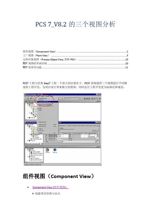
PCS7工程与经典Step7工程一个很大的区别在于,PCS7系统提供三个视图进行不同维度的工程开发,为项目设计带来极大的便利,同时也让工程开发更为标准化和规范:
组件视图(Component View)
Component View (组件视图):
创建项目结构与站点
硬件组态(HW-Config)和网络连接 (NetPro)
组件视图中可创建PCS 7项目、显示总线系统、自动化站,以及PC 站。
在PCS 7 中,通常可将下列对象插入一个子项目中:预先组态的 PCS 7 AS 站或 PCS 7 OS 站.
在组件视图中进行的工程和Step7工程方式一样。
SIMOCODE pro PCS 7 库函数开始指南说明书
Industrial Controls SIMOCODE pro SIMOCODE pro PCS 7 LibraryGetting Started10/2018Siemens AGDivision Digital Factory Postfach 48 483ZX1012-0CS16-5BC1Ⓟ10/2018 Subject to change Copyright © Siemens AG 2016. All rights reservedLegal informationWarning notice systemThis manual contains notices you have to observe in order to ensure your personal safety, as well as to prevent damage to property. The notices referring to your personal safety are highlighted in the manual by a safety alert symbol, notices referring only to property damage have no safety alert symbol. These notices shown below aregraded according to the degree of danger.indicates that death or severe personal injury will result if proper precautions are not taken.WARNINGindicates that death or severe personal injury may result if proper precautions are not taken.CAUTIONindicates that minor personal injury can result if proper precautions are not taken. NOTICEindicates that property damage can result if proper precautions are not taken.If more than one degree of danger is present, the warning notice representing the highest degree of danger will be used. A notice warning of injury to persons with a safety alert symbol may also include a warning relating to property damage.Qualified PersonnelThe product/system described in this documentation may be operated only by personnel qualified for the specific task in accordance with the relevant documentation, in particular its warning notices and safety instructions. Qualified personnel are those who, based on their training and experience, are capable of identifying risks and avoiding potential hazards when working with these products/systems.Proper use of Siemens productsNote the following:WARNINGSiemens products may only be used for the applications described in the catalog and in the relevant technical documentation. If products and components from other manufacturers are used, these must be recommended or approved by Siemens. Proper transport, storage, installation, assembly, commissioning, operation andmaintenance are required to ensure that the products operate safely and without any problems. The permissible ambient conditions must be complied with. The information in the relevant documentation must be observed.TrademarksAll names identified by ® are registered trademarks of Siemens AG. The remaining trademarks in this publication may be trademarks whose use by third parties for their own purposes could violate the rights of the owner.Disclaimer of LiabilityWe have reviewed the contents of this publication to ensure consistency with the hardware and software described. Since variance cannot be precluded entirely, we cannot guarantee full consistency. However, the information in this publication is reviewed regularly and any necessary corrections are included in subsequent editions.Table of contents1 Preface (5)2 Security information (7)3 Product specific security information (9)4 Introduction (11)4.1 Introduction (11)5 Getting Started (13)5.1 Installation (13)5.2 HW Config (14)5.3 CFC (17)5.4 Operator Station (23)6 References (35)7 List of Abbreviations (37)7.1 Abbreviations (37)SIMOCODE pro PCS 7 LibraryTable of contentsSIMOCODE pro PCS 7 LibraryPreface 1 Brief descriptionThe Getting Started of the SIMOCODE pro PCS 7 Library uses a simple example project toshow you the basic procedures:●Basic configuration steps●Handling and monitoring different signal blocks●ParameterizationThis Getting Started manual is intended to be an introduction and largely dispenses withdetailed information and background information.RequirementsBasic knowledge of creating a PCS 7 project is necessary. You will find information aboutConventionsThis documentation contains designations of the software interface elements. If you haveinstalled a multi-language package for the operating system, some of the designations willbe displayed in the base language of the operating system after a language switch and will,therefore, differ from the designations used in this documentation.Versions and documentationSIMOCODE pro PCS 7 LibraryPrefaceSIMOCODE pro PCS 7 LibrarySoftware required for the Getting Started of the SIMOCODE pro PCS 7 Library● You can execute the example project on any PC or programming device on which the following software is installed: – Windows operating system – Internet Explorer– Message Queuing service – SQL serverNoteThe versions required depend on the version of PCS 7 installed.You can find further relevant details in the following manuals:–on the – ● To do so, follow the instructions in the Process Control System PCS 7; Getting StartedHardware required for creating an example projectThis PCS 7 example project was created with the following hardware for the automation station (AS):Table 1- 1Hardware - Automation station 1: Configuration direct on the master systemOrder numberDescription6ES7 410-5HX08-0AB0 SIMATIC S7-400, CPU 410-5H with 1*DP and 2*PN interfaces6ES7 407-0KA02-0AA0SIMATIC S7-400, power supply PS 407 10A, AC 120/230V/10A standard PSTable 1- 2SIMOCODE HardwareOrder number Description3UF7 010-1A*00-0SIMOCODE pro V Basic UnitSecurity information 2 Siemens provides products and solutions with industrial security functions that support thesecure operation of plants, systems, machines and networks.In order to protect plants, systems, machines and networks against cyber threats, it isnecessary to implement – and continuously maintain – a holistic, state-of-the-art industrialsecurity concept. Siemens’ products and solutions constitute one element of such a concept.Customers are responsible for preventing unauthorized access to their plants, systems,machines and networks. Such systems, machines and components should only beconnected to an enterprise network or the internet if and to the extent such a connection isnecessary and only when appropriate security measures (e.g. firewalls and/or networksegmentation) are in place.For additional information on industrial security measures that may be implemented, pleasevisithttps:///industrialsecurity.Siemens’ products and solutions undergo continuous development to make them moresecure. Siemens strongly recommends that product updates are applied as soon as they areavailable and that the latest product versions are used. Use of product versions that are nolonger supported, and failure to apply the latest updates may increase customer’s exposureto cyber threats.To stay informed about product updates, subscribe to the Siemens Industrial Security RSSFeed underhttps:///industrialsecurity.SIMOCODE pro PCS 7 LibrarySecurity informationSIMOCODE pro PCS 7 LibraryProduct specific security information 3 Product specific security informationThis library is designed to run under the PCS 7 environment. Therefore, it is recommendedto follow the security principles for PCS 7 to support a secure operation, such as:●User rights●Password protection of–WinCCSIMOCODE pro PCS 7 LibraryProduct specific security informationSIMOCODE pro PCS 7 LibraryIntroduction 4 4.1IntroductionIntroductionThis document explains the basic principles of using the SIMOCODE pro PCS 7 Library. TheSIMOCODE pro PCS 7 Library is designed according to APL standards for both, blocks andfaceplates. This library contains CFC templates to fulfill the control functions of a MotorManagement device.For reducing configuration time on site, a module driver generator is included with thislibrary. By using this driver generator it is ensured that all necessary interconnections will behandled automatically by the system and the device is ready to operate in PCS 7environment.Custom configuration can be done by the user as well. User manual and online help will givedetailed information about the blocks and their input and output pins.This document will guide you through the necessary steps for using the template and themodule driver generator in a PCS 7 environment using a sample project. This sample usesminimum hardware, single station, one PLC connected to one SIMOCODE pro V viaPROFIBUS.PrerequisitesUserPCS 7 knowledge:●Project creation●HW-Config●CFC-Editor●WinCC-Explorer●WinCCYou can find the manuals for your PCS 7 Version in the manual collection.Introduction4.1 IntroductionSystem●Installed and compatible PCS 7 version●Installed SIMOCODE pro PCS 7 Library●PCS 7 Multiproject (created by Project-Wizard).Refer read me for this library for software details and steps to follow to change the existingproject to migration.CommunicationActive communication network between Engineering Station (ES)/Operator Station (OS) andthe PLC.Getting Started 5 5.1InstallationInstallationThe Setup program will guide you through the required steps. Use "< Back" and "Next >"buttons to navigate through the screens during the installation process. The installationprogram supports German and English. Please choose your language at the initial screen.The SIMOCODE pro library has two components:●AS = Components for Automation System●OS = Components for Operator StationFor example, this library has:●Library for SIMOCODE pro PCS 7 AS●Faceplates for SIMOCODE pro PCS 7 OSInstallation program will ask you to decide, which product you want to install. Below is thedecision matrix:AS OSSingle Station X XAS OSDistributed System Engineering Station X -Operator Station - X'X' - required, '-' - not required5.2 HW Config5.2HW ConfigHW ConfigOpen HW-Config and switch the hardware catalog profile to Standard.Below are the SIMOCODE pro objects for:Communication Integration Catalog pathPROFIBUS OM at PROFIBUS DP > Switching Devices >Motor Management SystemEDD PROFIBUS DP > Switching DevicesGSD PROFIBUS DP > Additional Field De-vices > Switching Devices >SIMOCODEPROFINET OM PROFINET IO > Switching devices >Motor Management SystemEDD1.2PROFINET IO > Switching devices >Motor Management System > GSD3GSDML1.21SIMOCODE pro V GSD (V1.5) and GSDML: Insert the Basic Type which meets yourrequirement.2The same object is used for GSD and EDD integration in HW-Config. Configuration viaPDM for EDD support needs to be activated by the user in Object Properties (Alt+Return) ofthe SIMOCODE pro Object.3Folder entry GSD will be created in case of parallel integration of SIMOCODE pro OM,integrated via SIMOCODE ES.Drag and drop the desired SIMOCODE pro-Object into the Station Window and connect itwith PROFIBUS resp. PROFINET line.5.2 HW ConfigBasic TypesThe length of the I/O data of the SIMOCODE pro device varies by the configured BasicType. The Basic Type defines how many valid data will be sent and received by the device inevery cycle. Bytes 2 and 3 are predefined and used for the max. Current I max. More bytes,supported by basic types 1 and 3, may be fed with user defined data. Following tablesdisplay the existing Basic Types along with the supported data length:Cyclic send data (SIMOCODE pro > PLC)Cyclic receive data (PLC > SIMOCODE pro)The following table shows which Basic Type is supported by the different SIMOCODE proBasic Units:Basic Unit Basic Type 1 Basic Type 2 Basic Type 3SIMOCODE pro C - X -SIMOCODE pro S X X -SIMOCODE pro V X X -SIMOCODE pro V PN X X X'X' - supported, '-' - not supportedSelect the Basic Type which meets your requirements in HW-Config catalog. Please finddetailed information about the Basic Type in the system manuals for SIMOCODE prodevices.5.2 HW ConfigInput AddressRetrieve the input address of the SIMOCODE pro device:NoteNote down the input address or insert it in symbol table of HW-Config (Options > SymbolTable or Ctrl+Alt+T) for later usage.Each address in the symbol table should have a valid symbolic name.5.3 CFC 5.3CFCMaster data libraryFor using the library in a plant, it is recommended to store the templates of the SIMOCODEpro PCS 7 Library in the Master data library. Since this is beyond the scope of thisdocument, we recommend you to take a look at:With the templates stored in the Master data library, follow the below steps.CFC Template1.Open CFC-Editor by double clicking on the desired CFC-Object.2.Select the tab Libraries, located underneath the Catalog view. If the templates ofSIMOCODE pro PCS 7 Library were placed in the Master data library, you will find themin the project library folder (Notation: "Project Name"+"_Lib" e.g.:GS_SIMOCODEpro_Lib). Otherwise you will find the templates in the SIMOCODE proLibrary (e.g.: SMCPro_PCS7_LibV90SP1).5.3 CFC3.Expand the Master data library node ("ProjName" + "_Lib" e.g.: GS_SIMOCODEpro_Lib).You will find two nodes:–Blocks–Charts5.3 CFC4.Expand the Charts node. Now you will see the SIMOCODE pro PCS 7 Library templates.SIMOCODE pro Library supports following control functions:Control Function TemplateDahlander Starter DahlandDirect Starter DirectMolded Case Circuit Breaker MCCBOverload Relay OvlRlyPole-Changing Starter PoleChngPositioner 1~5 PositnerDahlander Reversing Starter RevDahlReversing Starter ReversePole-Changing Reversing Starter RevPolChSoft Starter with Reversing Contactor RevSoftStrStar-Delta Reversing Starter RevStarDelSoft Starter SoftStrSolenoid Valve SolValveStar-Delta Starter StarDel5.Drag the desired template object (e.g.: Direct) by pressing left mouse button and drop theobject in the Chart view.Direct template is now instantiated.5.3 CFCOpen the Template1.Right click on the instantiated Direct template in the chart view and select Open. Thetemplate opens in a new chart view.Set I/OInput1.Scroll to the left, till you see the sheet bar. There you will find a textual interconnectionnamed Input Word Address of Simocode base Module.Now you have two options:–Setting the HW input address manually, as seen in HW-Config–Use symbol table for selecting the input address.Since this is a short example, we will just hand over the devices input address as it isdisplayed in HW-Config. We recommend using the symbol table for large projects. Refer2.Right click on Input Word Address of Simocode base Module and select Interconnectionto Address.A symbol table like dialog opens.5.3 CFC 3.Insert input address, in this case: IW512.4.Confirm input value by pressing enter. Now the blocks input address is connected to thedevices input address.MMMeas, MMStat and MMLogIf you want to use measurement, statistic values and/or logbook (MMMeas, MMStat and MMLog) for the SIMOCODE pro device, you need to switch to sheet view 2 in the CFC plan. There you will find the additional blocks for the mentioned functions.Repeat the Interconnection to Address, steps from above for this sheet.NoteIf you do not want to use the additional functions, you are free to delete the function blocks in question or all blocks in sheet 2.Result: The basic block set up is now complete.5.3 CFCGenerate module drivers1.Go to Chart > Compile > Chart as Program or hit Ctrl+B or click in the toolbar. TheCompile dialog opens.2.Ensure that the option Generate module drivers is checked in.3.Confirm dialog with the OK-Button.After compilation has finished, the Logs dialog will be displayed.1.Confirm this dialog by Close button.2.Now hit F5 in the chart view. The view will be updated and all textual interconnections arereplaced by the according block interconnection.DownloadThe CFC-Template is now ready for download.Go to CPU > Download or hit CTRL+L or use in the toolbar.Result: Template set up is now complete and ready to use.5.4 Operator Station 5.4Operator StationOperator StationBlock icons and faceplates are inserted in the project while compiling the Operator Station(OS). Compile OS. You can find details on how to work with the Operator Station in theBlock IconsAfter activating WinCC you will find the APL block icon for the motor block:Activate Block iconsThis library is also shipped with block icon for MMOprtn. It is disabled by default setting. Ifyou need MMOprtn block icon you can simply activate it:1.Open CFC-Editor.2.Select the MMOprtn block.3.Right click and select Object Properties in the context menu.4.Check in the checkbox for Create block icon.5.4 Operator Station5.Confirm the Properties dialog by clicking OK.pile the OS and activate WinCC. Now you will find two block icons: MotL andMMOprtn.5.4 Operator Station The block icons in detail are:MotLMotor - Large MMOprtnSimocode pro Direct starter OperationThe block icons give a general feedback of the current device status to the user. Pleaseopen a faceplate for detailed information about the device by clicking on the block icon.FaceplatesStandard faceplates of the block icons:NoteFor further information on how to use the Library, refer the latest "Programming andOperating Manual for the "SIMOCODE pro PCS 7 Library" Block Library.APL - MotL5.4 Operator StationMMOprtnMMMeas5.4 Operator Station MMStatMMLog5.4 Operator StationFaceplate-ViewsEach faceplate provides multiple views:APLSIMOCODE pro LibraryMotL MMOprtn MMMeas MMStat MMLog • Standard • Messages • Trends • Parameters • Preview • Memo • Batch• Standard • Messages • Limits • Trends • Preview• Status diagnostics • Event diagnostics • Warning diagnos-tics • Trip diagnostics • Station diagnostics • Process image • Batch• Current • Voltage • Analog • Temperature • Messages • Trends • Preview • Batch• Standard 1 • Standard 2 • Messages • Preview • Batch• Standard • Messages • Logbook • Preview • BatchYou can switch between the single views by clicking the demanded view button.Click onto open additional view buttons.Faceplates may be pinned or closed according to the demands of the user. Furtherinformation on how to use the faceplates can be found in the online help, shipped with this library or in the user manual provided for this library.5.4 Operator StationNavigation between faceplates1.Open the Standard view of block MotL.2.Click on button Operation.MMOprtn faceplate opens.Click on navigation button to return to the calling faceplate.5.4 Operator Station3.Click on button Measurement to open the MMMeas faceplate.5.4 Operator StationMMStat1.Open the Standard view of block MotL.2.Click on button Operation.MMOprtn faceplate opens.Click on navigation button to return to the calling faceplate.5.4 Operator Station3.Click on button Statistic to open the MMStat faceplate.5.4 Operator StationMMLog1.Open faceplate MMOprtn and switch to view Preview.2.Click on button Operation.MMOprtn faceplate opens.Click on navigation button to return to the calling faceplate.5.4 Operator Station3.Click on button Logbook to open the MMLog faceplate.NoteClick on navigation button at the MMMeas, MMStat or MMLog faceplate to return to thecorresponding MMOprtn faceplate.References6More informationAdditional information can be found as follows:●● ● ● ● ●ReferencesList of Abbreviations 7 7.1AbbreviationsOverviewTable 7- 1 Meaning of abbreviationsAbbrevia-MeaningtionAS Automation stationCFC Continuous Function ChartEDD Electronic device descriptionGSD Generic Station DescriptionHMI Human machine interfaceHW Config "Hardware configuration" module in the SIMATIC ManagerOM Object managerOS Operator stationPCS 7 Process Control System 7CPU Central Processing UnitSS Soft starterList of Abbreviations 7.1 Abbreviations。
西门子 过程控制系统 SIMATIC PCS 7 说明书

1-2相关产品目录信息和培训 ITC SIMATIC PCS 7SIMATIC PCS 7 过程控制系统附加程序订货号:E86060-W4678-A120-A3-7600STPCS7.A自动化和驱动技术 订货号:印刷版:E86060-K6850-A101-B4光盘版:E86060-D6850-A100-B9-7400SIMATIC全集成自动化部件订货号:E86060-K4670-A111-A8-7600 ST 70自动化部件订货号:E86060-D4001-A100-B8-7600 CA 01SIMATIC HMI 人机界面系统订货号:E86060-K4680-A101-B1-7600 ST 80A&D Mall网址:www.siemens.de/automation/mallSIMATIC NET工业通讯和现场设备订货号:E86060-K6710-A101-B3-7600 IK PITELEPERM M 自动化系统 AS 488/TM订货号:E86060-W3812-A100-A3-7600 PLT 112过程自动化现场仪表订货号:E86060-K6201-A101-A3-7600FI 01商标该产品目录中所有带有“®”的名称均为西门子公司的注册商标。
该产品目录中的其它名称可能是商标,若由第三方用于其目的,可能会侵犯所有人的权益。
所有以英制(英寸)表示的数据只根据“计量单位法”用于出口。
1-2过程控制系统SIMATIC PCS 7产品目录ST PCS 7・2003年10月取代:产品目录ST PCS 7・2003 年 5 月该产品目录中所及产品也包含在光盘版产品目录CA 01 中订货号:E86060-D4001-A100-B9-7600请与当地的西门子代表处联系西门子公司版权所有 © 2003本产品目录中所及产品和系统均根据DQS 认证的质量管理体系(证书号:1323-03)生产,符合标准 DIN ENISO 9001。
西门子 PCS 7 系统文档

SIMATICPCS 7 系统文档V7.0 SP1文档说明请仔细阅读这些说明,其中包含了有关PCS 7 系统文档手册的重要信息以及补充内容。
以PDF 格式提供的电子手册的大部分内容与SIMATIC 管理器(“帮助”(Help) >“主题”(Topics))中在线帮助(“PCS 7 基本文档”(PCS 7 Basic Documentation))的内容相同。
由于存在与发布最终期限相关的工艺流程方面的问题,电子手册与在线帮助可能会略有差别。
如果存在差异,可将在线帮助和自述文件中的信息视为最新信息。
打印本文件时,请确保将A4 纵向格式的左、右页边距宽度设置为25 毫米(约 1 英寸)。
目录1产品文档说明2PC 组态与授权手册3入门指南4工程系统组态手册5操作员站组态手册6PCS 7 OS 过程控制操作说明7软件更新手册8SIMATIC 管理器中的“PCS 7 基本文档”在线帮助9高精度时间戳手册10PCS 7 安全概念11集成MES 功能12PCS 7 相关信息:WinCC OPC A&E 服务器12.1WinCC V6.2 SP2:在PCS 7 中使用的带层级访问的OPC A&E 服务器12.2OPC A&E 服务器的功能12.3具有PCS 7 V7.0 SP1 的OPC A&E 服务器12.3.1OPC A&E 与带层级访问的OPC A&E 之间的差异12.3.2如何将OPC A&E 升级到PCS 7 V7.0 SP112.4在OPC A&E 上映射WinCC 消息系统12.4.1映射WinCC 消息系统12.4.2映射消息优先级12.4.3WinCC 消息系统的属性12.4.4确认原理12.5OPC A&E 的质量代码12.6带层级访问的OPC A&E 的PCS 7 应用实例12.6.1实例1:未为消息分配区域12.6.2实例2:为消息分配了区域12.6.3实例3:为区域的消息分配了报警隐藏组1 产品文档说明用户界面元素的名称,如菜单命令和对话框的名称根据手册的语言,采用德语/英语/法语用户界面名称。
PCS7培训教材教程

前言 什么是PCS,有何优点
•
PCS即Process Control System的缩写,意思是“过程控制系统”。由于组成该系统的
控制器都是由西门子S7系列的PLC(cpu414-3以上)组成,因此叫做PCS S7,实质上PCS S7
即 西 门 子 的 D C S 。 P C S S 7 的 总 线 网 络 由 A S I ( 异步串行接口) 现 场 传 感 器 总 线 , P r o f i b u s D P/ PA
产流程或主要流程以及下游流程,直到输出物流。由此促进了整个公司运作的优化,包括企
业资源规划级、制造之星系统级、过程控制级直到现场级。
•
SIMATIC PCS S7 不仅可以集成在生产现场的整个自动化解决方案中,实现主要过程的
自 动 化 , 而 且 还 可 以 通 过 基 于 P L C 或 P C 的 S I M AT I C 部 件 , 实 现 生 产 现 场 的 辅 助 流 程 ( 例 如 罐
可用于每个软件组件。即使同时有几位技术人员操作统一项目,亦能确保数据的一致性。在
工程师站定义的参数也可传送到现场中传感器、执行机构或驱动器。
• ES • AS • OS • 现场设备 • 总线系统
系统成员
现场总线类型及用途:
PROFIBUS-DP 用于PLC与分布外设(如ET200S,ET200)间通信 PROFIBUS-PA 用于现场传感器与执行器间的低速数据传输
如何完成一个项目?
1.Simatic manager
2.新建项目
选择CPU型号
信总 线数量
编辑工厂层次的级数
根据系统配置选择 PCS7 OS的类型
组件视图 工厂视图
过程对象视图
PCS7使用入门(工程师培训)
SIEMENSSIMATIC过程控制系统PCS7使用入门手册前言,目录1简介2建立一个项目3使用CFC编辑器4使用输入/输出助手5使用SFC编辑器6编译,下载及测试7使用操作员站前言过程控制系统有了PCS7,你就已经购买了一个过程自动化系统,通过它你可以自动化、控制和监控一个过程的运行。
使用入门手册和项目入门包括了一个手册,解释了建立一个COLOR_GS项目所必需的每一步,以及完成COLOR_GS项目。
你可以在现有的SIMATIC站上运行项目。
也许有必要将项目和硬件的部件相适应。
“过程控制系统PCS7—电气手册”CD也包含了该入门手册。
你可以使用浏览器阅读和打印该手册。
当你安装了PCS7,COLOR_GS项目和本手册会拷贝到你的编程装置或者PC机。
当需要时,你可以打开手册“开始>SIMATIC>S7手册>PCS7入门手册”。
你可以在SIMATIC管理器打开项目如下:1.选择菜单命令“File>Open”.2.点击“Sample Project”键。
3.选择“COLOR_GS”库,并且点击“OK”键。
COLOR_GS项目也要求COLOR_GL库,包含了模型功能图。
你可以打开库如下:1.选择菜单命令“File>Open”;2.点击“Libraries”键;3.选择“COLOR_GL”库,并且点击“OK”键。
“PCS7使用入门”和“PCS7配置手册”在PCS7的安装CD上的“手册\英语”中,以pdf文件存放。
本“使用入门”手册在一个例子的基础上,给你介绍了如何建立一个项目以及监控过程,。
一步一地,你将学会建立一个简单任务的程序。
5--PCS 7中如何使用APL的DoseL功能块

PCS 7中如何使用APL的DoseL功能块1 DoseL功能概述在工业领域,尤其是流程工业中,大量存在原料、中间产品等的给料定量控制需求,APL的DoseL功能正是面向这种控制任务的高级功能块。
除了可以实现正常的给料控制之外,还可以实现如下功能:- 管道泄漏量补充(Dribbling)通过定义修正因子,可以实现动态修正管道残料泄漏量对于定量控制影响;- 补充给料(Post Dosing)如果出现给料不足的现象,根据功能块的设置,可以实现后期的补充给料。
给料过程按照设定的时间来执行。
- 粗给料(Coarse Dosing)和精细给料(Fine Dosing)整个下料过程可以分为粗给料和精细给料两部分,具体工艺体现可以是两个不同管径的阀门控制,或者是两个不同设定值的流量控制。
以此来提高定量的准确性。
DoseL功能的工作过程如下图所示:图 1 DoseL功能块工作流程图通过面板上的“Start”按钮(或者“Resume”)进入给料过程,其中:阶段1:实际给料量达到或者超过设定值;阶段2:实际给料量达到设定值和上次泄漏量的差值,以此进入泄漏累计阶段;阶段3:如果在Feature中设置自动泄漏累计,则累计结束之后会自动进入给料过程;阶段4:联锁条件激活;阶段5:联锁条件消失,或者给料不足时,点击Continue继续进行补充给料过程;阶段6:泄漏量累计阶段之后,如果还是给量不足,则进入OFF状态;阶段7:暂停之后,联锁条件激活,也进入OFF状态;阶段8、9和10:给料过程被取消,结束给料。
需要注意的是,OFF只是表示给料过程停止,而非结束。
End表示给料结束。
2 DoseL块的应用根据给料具体的控制方式,DoseL块的使用主要有如下几种方式:- 给料流量PID控制DoseL块配合管道上的一个给料流量PID回路来实现定量;- 给料双流量PID控制给料通过两个不同管径的管道,每个管道上分别设置一个流量控制,来实现粗、精细配合给料;- 给料阀门开度控制在给料管道上安装一个模拟阀门,通过DoseL来控制阀门开度。
PCS7 斜坡用法

1.RAMP_P块概述在PCS 7中,RAMP_P实现了模拟量的斜坡函数功能。
(注:在PCS 7 V7.1 高级过程库(Advanced Process Library, APL)中,很多功能块,例如PID控制块,已经集成了更为丰富的斜坡控制功能,详情请参考文档:“PCS 7 V7.1 APL库中的斜坡(Ramp)功能”78818263RAMP_P的块号是FB52,通过CFC进行调用,安装在循环中断OB(OB30~OB38)中。
以PCS 7 V7.0 SP3为例,如图1,在PCS 7 Library V70中,Blocks+Templates\Blocks下CONTROL中找到RAMP_P,拖入相应CFC中即可。
2.RAMP_P块调用及基本管脚介绍RAMP_P功能块管脚如图2。
更详细内容可选中RAMP_P块,按F1键参考在线帮助信息。
图2 RAMP_P块管脚管脚说明:URLM: 斜坡上升斜率DRLM: 斜坡下降斜率U: 模拟量输入RATE_OFF: 关闭斜坡功能QLIM_U: 斜坡上升标志位QLIM_D: 斜坡下降标志位V: 模拟量的斜坡输出3.RAMP_P功能块工作方式RATE_OFF=1时,关闭斜坡功能,V=U。
RATE_OFF=0时,输出V会以URLM或者DRLM为斜率上升或下降。
以RAMP_P与CTRL_PID 的SP_EXT连接为例,当前SP_EXT=100;图3 RAMP_P连接实例如果新的SP_EXT=200,则RAMP_P的U=200, V输出会以URLM=3为斜率上升,QLM_U=1;如果新的SP_EXT=0, 则RAMP_P的U=0, V输出会以DRLM=3为斜率下降, QLM_D=1。
关键词PCS 7,标准库,CFC,RAMP_P,斜坡函数,CTRL_PID。
SIMATIC 过程控制系统 PCS 7 维护站 V9.1 功能手册说明书

3.12
PAM 站 ........................................................................................................................ 39
4 附加文档 ........................................................................................................................................ 43
维护站 V9.1
功能手册, 02/2021, A5E49490728-AA
3
目录
5.7.4
如何为 MS 或 OS/MS 客户端组态 PC 站......................................................................... 56
5.8 5.8.1 5.8.2 5.8.3 5.8.4
3.2
具有诊断功能的对象.................................................................................................... 20
3.3
“PC 站”区域 ............................................................................................................... 21
3.10
具有多个 OS 单工作站系统的工厂组态中的 MS ............................................................ 34
PCS 7 V7.1 SP1 APL库阀门功能块VlvL使用入门
PCS 7 V7.1 SP1 APL库阀门功能块VlvL使用入门显示订货号1. APL库介绍PCS 7 V7.1 SP1为西门子最新一代DCS控制平台,为满足不同行业、不同用户的控制要求,其提供了丰富的控制功能库。
功能库有PCS 7 AP Library V71、PCS 7 BasisLibrary V71和PCS 7 Library V71。
PCS 7 AP Library(本文将缩写为APL)为高级过程库(非先进过程控制),为V7.1以上版本所提供的全新功能库,其在原有基本控制算法的基础上,增加了许多新的特性,例如,功能块特性参数(Feature)定制,远程/就地模式控制,面板关联,互锁控制,辅助值显示等,可以满足不同行业、不同习惯用户的各种不同应用需求。
而且高级过程控制库带有全新V7.1显示风格的图标和面板,显示界面更加丰富,操作方式更加贴近人体工程学的要求。
图1库图关于APL库的更多信息请参考开始菜单→ SIMATIC → Documentation → English下的“PCS 7 –Manual for advanced process library V7.1”文档和相关在线帮助。
其中为满足不同用户、不同行业的控制习惯要求,APL库加入的特性参数(Feature)定制功能,请参考上述手册中的1.5章节。
此文主要将主要介绍APL中的VlvL阀块的使用。
附加信息:PCS 7 V7.1 SP1同时提供的另外两个功能库中,PCS 7 BasisLibrary 为基本库,提供PCS 7所需的所有诊断功能块,如CPU_RT,SUBNET,OB_BEGIN等系统块。
由系统在编译过程中自动调用,不能在用户程序中人为调用。
PCS 7 Library则相当于以前版本的PCS 7 Standard Lib库,包括了原有功能库中除BasisLibrary块之外的其他所有功能块,为兼容原有版本而保留。
2 .VlvL块基本特性介绍PCS 7 V7.1 SP1中,APL库VlvL功能块主要用于控制两位(打开/关闭)阀门,可以实现阀的手动控制、自动控制、就地控制等;控制命令可以为单点的高低电平开关也可以为双点的脉冲控制开关;阀门的打开或关闭过程中可以实行安全的连锁保护控制等。
PCS7_OS Download功能(OS下载)与步骤(工程师培训)

PCS7_OS Download功能(OS下载)与步骤
一个PCS7系统中,往往有多个OS项目,除去ES站本机运行的OS项目外,其它项目都必须加载到网络中的其它目标计算机上运行,例如,OS服务器与OS客户机,OS 单站及以其为模板的OS索引站等。
将开发好的OS项目传递到目标计算机的方式为OS下载。
通过选中对象
OS->PLC->Download下载。
在PCS7系统中,不能通过WINCC项目复制器/移植器或直接拷贝的方式传递项目。
OS下载成功后,即可在目标计算机上激活OS项目进入运行模式。
OS下载前的准备
∙已经为该OS进行过PC站组态和下载
∙已经执行了OS编译(OS客户机不需要编译)
∙必须为OS项目分配一个目标计算机的下载路径
OS完全下载与仅更改下载
在PCS7中有两个可用于下载的选项:完全下载(Entire Program)与仅更改(Change-Only)下载。
如果执行OS完整编译,则必须进行完整下载(要求OS停机)
OS不停机下载的条件
下载类型说明条件。
西门子 过程控制系统 SIMATIC PCS 7 技术手册

03. 2009SIMATIC PCS 7SIMATIC PCS 7 —助您超越极限!最新版 SIMATIC PCS 7 V7.0 是国际上居于领先地位的过程控制系统之一,具有丰富多样的功能,应用灵活且性能强大,可用来实现创新解决方案,应对过程工业领域的特殊挑战。
SIMATIC PCS 7 的系列功能和应用范围远远超出了典型过程控制系统的极限,可为您带来意想不到的可能和众多崭新的前景。
SIMATIC PCS 7 可以无缝嵌入到西门子的全集成自动化系统(TIA)中,充分利用适用于工业自动化所有层次级别(从企业管理层、控制层直至现场层)且能够完美配合的产品、系统和解决方案。
根据客户的具体要求,在制造业、过程工业以及混合型行业等所有行业完成自动化控制任务。
2系列产品和系统的通用性以及以此为基础的解决方案所具有的主要优点就在于:能够利用共同的硬件、工程和管理工具,实现连续过程和间歇过程、快速精确的控制流程以及集成安全功能的自动化。
所有组件之间均能完美配合,从而确保您能够始终以最高质量进行生产。
七大优势系统优点SIMATIC PCS 7 是具有卓越系统特性和独特可升级结构的通用过程控制系统,它将灵活的模块化冗余技术以及统一的数据管理、通讯和组态等强大的性能组合在一起,是以经济、高效的方式组建和运行控制技术工厂的理想基础。
SIMATIC PCS 7 还具有常规过程控制系统所不具备的优点。
它具有灵活的系统结构,可以随时根据要求通过无缝集成附加功能的方式扩展控制技术功能,例如可用于批次过程自动化、物料传送控制、资产管理、安全应用、过程数据分析/管理或 MES 任务。
选用 SIMATIC PCS 7 的七大优势:• 可通过集成方式降低总运行成本(总拥有成本)• 具有卓越的性能与品质,可进行高效工程,同时具有极高的可靠性和可用性• 具有灵活性和可升级性—从小型实验室系统,直至大型工厂网络均可使用• 可以对自有系统和第三方系统逐步进行现代化改造,因此可保护投资安全• 安全和防范—集成安全技术以及丰富的 IT 安全功能,使人身、环境、过程以及工厂的安全得到可靠保护• 持续不断的技术创新—源自全球居于领先地位的自动化技术供应商• 遍布全球的专家网络—可通过遍布全球的专家与授权合作伙伴网络提供本地化服务和技术支持4通过集成方式降低总运行成本可以水平集成在全集成自动化系统中西门子的全集成自动化系统(TIA)是能将适合于工业自动化所有层次的产品、系统和解决方案进行完美协调后无缝集成在一起的平台。
PCS 7_V8 OS冗余客户机服务器结构配置(工程师培训)
目录
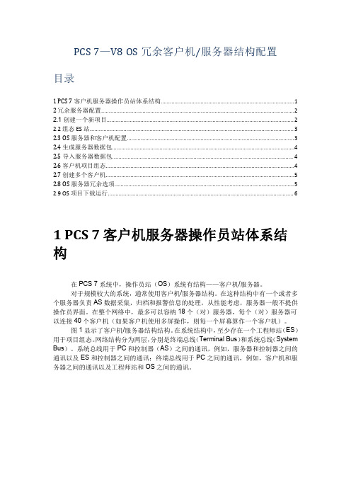
1 PCS 7 客户机服务器操作员站体系结构.......................................................................................1 2 冗余服务器配置..............................................................................................................................2 2.1 创建一个新项目.......................................................................................................................... 2 2.2 组态 ES 站..................................................................................................................................... 3 2.3 OS 服务器和客户机配置.............................................................................................................3 2.4 生成服务器数据包.......................................................................................................................4 2.5 导入服务器数据包...................................................................................................................... 4 2.6 客户机项目组态...........................................................................................................................4 2.7 创建多个客户机...........................................................................................................................5 2.8 OS 服务器冗余选项.....................................................................................................................5 2.9 OS 项目下载运行......................................................................................................................... 6
PCS系统操作培训资料

2线循环系统设计
3线循环系统设计
输调漆管线
输漆管线按两线制设计,分为供漆管、返回管和 支管。供漆管由调漆间泵模组输出口开始,沿喷 室铺设至各枪站,经支管供至喷枪后,再经返回 管返回调漆间的油漆循环桶内里。它将涂料、溶 剂、空气等以一定的流量、流速、压力输送至枪 站,供喷枪使用,相当于血管。 为了保证管路中涂料有足够流速(通常主管流速 为60英尺,支管为30英尺),供漆管和返回管要 多次变径,外侧包有保温套。 泵设计输出量为枪站总喷涂量的3倍
环流系统的设计 在喷涂室周围提供环流管道, 直到最后一台工作站为止。 返流从第一台供料的工作站开始, 并与供料管道平行, 最终 返回到调漆室。 这种设计能为喷涂室的一端到另一端提供较大的供料压力 差。 一般要求较高的供料压力 最适用于小型工业企业的送料系统
完全循环到枪
3线循环系统 线循环系统 供
PCS系统操作培训资料 系统操作培训资料
培训目的,内容,要求: 培训目的,内容,要求:
了解PCS系统的种类及其构成、原理; 掌握必要的系统安全知识和操作方法,会开机关机 熟悉系统和主泵状态的正常和异常;常见异常现象的处理;紧急情况 下的应急处理; 熟悉泵和稳压器、过滤器、背压器等主要部件结构、安装、维护方法; 了解附属设备的原理、操作方法; 了解喷涂的种类及其特点 熟悉喷枪的基本结构、调整、喷涂方法。
输漆管线
3.枪站 .
枪站由多路涂料、溶 剂及空气接口组成,含 有各种快换接头、阀门、 调压器、软管等。喷枪 接至枪站相应出口,即 可获得涂料、空气等供 应,进行喷涂作业。
4.控制系统 对油漆的温度、流量、压力等参数进行 调控、监测,有设定、控制、显示、报 警、记录等功能,并可将数据经网络上 传至中控室。
PCS 7 V8.0 培训
选择
For internal use only
PCS 7 V8.0 欧洲版培训 基础篇-修改项目基本设置
修改层级属性
层级名称
画面导航顺序
2012-02-21
OS显示名称 点击
For internal use only
PCS 7 V8.0 欧洲版培训 基础篇-编制用户程序
插入CFC程序
右键
2012-02-21
● 安装消息队列服务Message Queuing和 Microsoft Internet 信息服务IIS
● 只有IE8是被允许的浏览器
● 安装PCS7之前修改计算机名,安装完之后
2012-02-21
For internal use only
PCS 7 V8.0 欧洲版培训 基础篇- 操作系统的安装
打开PCS7→文件→“新建”:在项 目插入组件
项目中插入组件
AS:CPU OS:单站或者服务器
OS:客户机
2012-02-21
For internal use only
PCS 7 V8.0 欧洲版培训 基础篇-新建项目(非向导模式)
打开PCS7→文件→“新建”:AS站硬件组态
双击组态硬件 机架:Rack-400 电源:PS-400 CPU:CPU-400 通讯板:CP-400
打开多项目Tisco_4350_MP
打开项目
2012-02-21
For internal use only
PCS 7 V8.0 欧洲版培训 基础篇-修改项目基本设置
修改项目语言设置
右键:对象属性
设置项目的语言环境
2012-02-21
For internal use only
- 1、下载文档前请自行甄别文档内容的完整性,平台不提供额外的编辑、内容补充、找答案等附加服务。
- 2、"仅部分预览"的文档,不可在线预览部分如存在完整性等问题,可反馈申请退款(可完整预览的文档不适用该条件!)。
- 3、如文档侵犯您的权益,请联系客服反馈,我们会尽快为您处理(人工客服工作时间:9:00-18:30)。
PCS 7 -APL库中的斜坡(Ramp)功能
(工程师培训)
编写:
审核:
培训对象:系统工程师
目录 ................................................................................................................ 错误!未定义书签。
1. 斜率限制关闭时,手动斜坡操作 (2)
1.1 手动斜坡操作的前提条件 (2)
1.2 手动斜坡操作的两种实现方式 (2)
1.3 手动斜坡操作 (4)
2. 打开斜率限制 (6)
3. 具有Ramp功能的功能块 (8)
1. 斜率限制关闭时,手动斜坡操作
1.1 手动斜坡操作的前提条件
∙PID块处于自动控制模式下,设定值为内部给定。
如图1。
图1 PID控制模式
∙关闭斜率限制。
在面板Ramp视图下关闭Gradient limits on功能(CFC中SP_RateOn=0)。
如图2。
图2 关闭Gradient limits on功能
1.2 手动斜坡操作的两种实现方式
∙设置时间范围
通过面板选择Ramp mode为Duration或者在CFC中设置SP_RmpModTime=1。
如图3。
这种方式下,当前设定值会在设置Duration时间内到达Target setpoint。
