【推荐下载】海洋光学为USB2000+光谱仪新增触发选项
Ocean Optics 光谱仪 FPG 固件版本 3.0 及以上的新外部触发选项说明书
New External Triggering OptionsInstructions for Spectrometers withFirmware Version 3.0 and Above OverviewOcean Optics spectrometers with FPGA Firmware Version 3.0 and above provide several methods of acquiring data (see table below). In the Normal/Free-Run mode, the spectrometer is “free running.” That is, the spectrometer is continuously scanning, acquiring, and transferring data to your computer, according to parameters set in the software. In this mode, however, there is no way to synchronize the scanning, acquisition, and transfer of data with an external event. However, trigger pulses for synchronizing an external event with the spectrometer are available.To synchronize data acquisition with external events, other modes of acquiring data are available. Each mode involves connecting an external triggering device to the spectrometer and then applying an external trigger to the spectrometer before the software receives the data. The length of the integration time and the source for the integration clock depend upon the mode chosen. All other acquisition parameters are set in the software.Also see the External Triggering Options Instructions for triggering information for other Ocean Optics spectrometers with firmware versions below 3.0.Triggering Mode Description Use This Trigger Mode When You …Normal/Free-Run Spectrometer acquires spectracontinuously.No synchronization to other events is neededSoftware Integration time is set in the software.Software receives a trigger event andtransmits spectra obtained in the dataacquisition cycle in which the triggeroccurred.Are using a continuous illumination source, and the light intensity is constant before, during, and after the trigger.Need to set the integration time in the software.External Triggering Options Instructions for FW3.0and AboveTriggering Mode Description Use This Trigger Mode When You …External Hardware Level Trigger Integration time set via software on achip in spectrometer. The spectrometerwaits for a sharp rise in voltage on thetrigger input pin, and then acquiresspectra until the voltage is removed.Need a continuous acquisitionwhenever a certain condition is met,such as:-when reacting to a sample beingpresent or-when a sample reaches a specificstate that you want to measureExternal Synchronous Trigger Spectrometer acquires data from anexternal trigger event (such as a pushbutton) until the next time the trigger isactivated, at which time thespectrometer ceases spectralacquisition and begins a newacquisition. Integration time cannot beset, since the trigger can fire at randomintervals.Must synchronize your scans to anexternal clock sourceAre using a lock-in amplifierAre using a chopperExternal Hardware Edge Trigger Integration time set via software on achip in spectrometer. The spectrometerwaits for a sharp rise in voltage on thetrigger input pin, and then acquiresspectra.This trigger acquires onespectrum each time that there is asharp rising edge (if an acquisition isnot already in progress).Are using a pulsed excitation source orlight source in your experiment (suchas a laser or flash lamp)Are doing LIF (fluorescence withpulsed excitation) or phosphorescenceexperimentsNeed to synchronize an acquisitionwith an external eventSetting Up for External Triggering IMPORTANT:Voltage RegulationThe maximum recommended voltage on the Triggering Pin is 5.5 V.If your triggering device exceeds this voltage, you must regulate or condition the signal (via transistor buffering, transformer isolation or opto-isolation, for example) or isolate the signal from the spectrometer.NoteTo use one of the External Triggering options, you must know the specifications andlimitations of the triggering device. The design of the triggering device may prevent youfrom using one of the external triggering modes as it is described in these pages.External Triggering Instructions for FW3.0and Above Pinout Diagrams for Ocean Optics SpectrometersHR4000,HR2000+,Maya2000Pro and Maya-LSL and Maya-LSL,NIRQuest,QE65000, QE65Pro, and QE ProFor external triggering,supply a line from Pin 10 of the multi-pin connector on the spectrometer to your triggering device.Be sure to also use the Ground Pin when triggering. See the appropriate spectrometer Data Sheet to locate the ground pin(s).Pin-out Diagram of 30-pin Connector on HR4000,HR2000+,NIRQuest,Maya2000Pro and Maya-LSL,QE65000, QE65Pro,and QE Pro SpectrometersUSB2000+ and USB4000For external triggering, supply a line from Pin 7 of the multi-pin connector on the spectrometer to your triggering device. Be sure to also use Ground Pin 6 when triggering.Pin-out Diagram of 22-pin Connector on USB2000+, Flame-S,USB4000, and Flame-T SpectrometersFlame-S,Flame-T, and Flame-NIRFor external triggering, supply a line from Pin 2of the multi-pin connector on the spectrometer to your triggering device. Be sure to also use Ground Pin 1when triggering.When facing the 40-pin Accessory Connector on the front of the vertical wall of the Flame, pinnumber 1 is on the right.Pin-out Diagram of40-pin Connector on Flame-S,Flame-T and Flame-NIR SpectrometersExternal Triggering Options Instructions for FW3.0and AboveSetting Integration Time in SoftwareSoftware,External Hardware Level Trigger and External Hardware Edge Trigger modes can have the integration time set via OceanView or SpectraSuite.Set Integration Time with OceanViewUse the Main Controls of the Set Acquisition Parameters in OceanView to select the trigger mode and to set the integration time.The Automatic button in the Integration Time control box automatically adjusts the spectrometer’s integration time to bring the highest point of the signal to 85% of full saturation value. This value is represented by the horizontal blue line on the preview graph.External Triggering Instructions for FW3.0and AboveThe integration time may also be set manually by using the numeric spinner control and the drop-down units menu.Note that the Nonlinearity Correction control is grayed out until the Electric Dark control is enabled.Also note that once a triggering mode for the spectrometer has been set, the device will wait for an external trigger before continuing. It will appear as though the spectrometer has locked up and no further data acquisitions will occur until the External Trigger pin on the device receives a signal.External Triggering Options Instructions for FW3.0and AboveSet Integration Time with SpectraSuiteUse the External Trigger selection box on the Trigger toolbar to set the trigger mode of the spectrometer to Software.NoteOnce you select an external trigger mode, your computer will appear unresponsive. Thisis normal, as the computer is waiting for a trigger. You must apply one more trigger tothe spectrometer after selecting a new trigger mode.External Triggering vs. Triggering an External EventThere could be some confusion between the concepts of External Triggering and triggering an external event. The following sections explain each of these concepts:∙External Triggering–An event outside the sampling system (such as a push button, lever activation, or laser pulse) triggers the voltage level on the spectrometer’s trigger pin and instructs the spectrometer to begin spectra acquisition.∙Triggering an External Event–When triggering an external event, the spectrometer instructs an external device (typically a lamp such as the PX-2 or the LS-450) to illuminate immediately prior to spectral acquisition.Trigger Mode DescriptionsThe following sections specify the Trigger modes for Ocean Optics spectrometers with firmware versions 3.0 and above and associated timing sequences.For the Maya2000Pro and Maya-LSL,NIRQuest,Flame-NIR,HR2000+,USB2000+, Flame-S,HR4000, USB4000,and Flame-T,the timing sequences specified are for the trigger mechanism interacting with a single-depth FIFO.The hardware implementing these Trigger modes may enhance the capability and performance by implementing buffering schemes using larger or multiple FIFOs.For the QE65000,the timing sequences specified are for the trigger mechanism interacting with a triple-depth FIFO. The hardware implementing these Trigger modes enhances the capability and performance by implementing a buffering scheme using multiple FIFOs.In addition, the QE Pro has a 15,698-deep buffer.External Triggering Instructions for FW3.0and Above Normal ModeIn the Normal (Free-run) mode, the spectrometer will acquire one spectrum for each “get spectrum”command issued from the host software.The integration time for each spectrum is pre-programmed prior to the host issuing its “get spectrum” command.The spectrometer waits in a repetitive idling loop until it receives the next “get spectrum” command.Once the command is received, the spectrometer exposes the detector for the pre-programmed integration time, and its resulting spectrum is written to an internal FIFO.The spectrometer signals the host that a spectrum is ready, and the host reads out the new spectrum.Upon reading out the new spectrum, the host immediately commands the spectrometer to acquire the next spectrum.In this process, the spectrometer is responding “on-demand”to the host’s “get spectrum” commands.The spectrometer waits in an idle state between each spectrum and the next “get spectrum” command.The spectrometer does not pre-fetch any spectra in anticipation of the next “get spectrum” command.For the QE65000spectrometer, integrations are continuously performed with the most recent three spectra available to the host software. The QE65000 has an internal FIFO which can hold up to three contiguous spectra.To maximize throughput, the QE6500 is constantly pre-fetching spectra back-to-back, independent of the host’s “get spectrum” command.However, if the host fails to issue a “get spectrum” command by the time the third spectrum is pre-fetched, the QE65000 clears its FIFO and starts 3 new acquisitions.In this process, the QE65000 is pre-fetching back-to-back spectra in anticipation of the host’s “get spectrum” command.For the QE Pro, there are no idle cycles that drop new spectra; all new spectra are stored in the buffer and are available to the user (if buffering is enabled). If the buffer limit is exceeded (15,698), the oldest spectrum is automatically discarded to make room for the new spectrum. The user can clear the buffer at any time.External Triggering Options Instructions for FW3.0and AboveNormal Mode Timing SequenceSoftware Trigger ModeIn this level-triggered mode, the spectrometer is “free running,” just as it is in the Normal mode. The spectrometer is continually scanning and collecting data. With each trigger, the data collected up to the trigger event is transferred to the software. If you continuously apply triggers (for example, by holding down the button on via an external switch), this mode is equivalent to operating in the Normal mode.In the Software Trigger mode, you set the integration time (as well as all other acquisition parameters) in the software.The source for the integration clock comes from the A/D converter.External Triggering Instructions for FW3.0and Above If the software trigger is asserted during integration cycle n, the photons from this integration period will be readout and digitized at the start of integration cycle n+1External Software Triggering–Trigger TimingExternal Synchronous Trigger ModeIn the External Synchronous Trigger Mode, two external triggers are required to complete a data acquisition. The first rising edge starts the integration period and the second rising edge stops the integration while starting the next integration. Thus the integration time is the period between the two external trigger pulses. After the each integration period, the spectra is retrieved and written to the FIFO in the FPGA.For the Maya2000Pro and Maya-LSL, HR2000+,USB2000+,Flame-S and Flame-NIR,as in all nonbuffered modes, no further integrations are possible until the software has read the entire contents of the FIFO.For the QE65000, three spectrum buffers provide software with the most recent spectral acquisitions.External Triggering Options Instructions for FW3.0and AboveExternal Synchronous Trigger Mode Timing SequenceExternal Hardware Level Trigger ModeIn the External Hardware Level Trigger mode, a rising edge detected by the FPGA from the External Trigger input starts the Integration Cycle specified through the software interface. After the Integration Cycle completes, the spectrum is retrieved and written to the FIFO in the FPGA. As long as the trigger level remains active in a logic one state, continuous acquisitions will occur with the following exception. Each subsequent acquisition must wait until a minimum CCD Reset Cycle completes. This Reset Cycle insures that the CCD performance uniform on a scan-to-scan basis. The time duration for this reset cycle is relative to the Integration Cycle time and will change if the integration period is changed. So the timing sequence is Trigger, Trigger Delay,Integration Cycle, Read/Write Cycle, Reset Cycle, Idle Cycle(s), and Integration Cycle (if trigger is still high). The Idle Cycle will on last 2µs if the trigger remains high and the FIFO is empty and a spectrum request is active, otherwise the Idle Cycle will continue until all 3 conditions are satisfied.For the Maya2000Pro and Maya-LSL, HR2000+,USB2000+,Flame-S and Flame-NIR, as in all nonbuffered modes, no integrations are possible until the software has read the entire contents of the FIFO.External Hardware Level Trigger Mode Timing SequenceFor the QE65000, three spectrum buffers provide software with the most recent spectral acquisitions.QE65000 Hardware Level Trigger ModeQE Pro Hardware Level Trigger ModeExternal Hardware Edge Trigger ModeIn the External Hardware Edge Trigger mode, a rising edge detected by the FPGA from the External Trigger input starts the Integration Cycle specified through the software interface. After the Integration Cycle completes, the spectrum is retrieved and written to the FIFO in the FPGA followed by a CCD Reset Cycle. Only one acquisition will be performed for each External Trigger pulse, no matter what thepulse’s duration is. The Reset Cycle insures that the CCD performance uniform on a scan-to-scan basis. The time duration for this reset cycle is relative to the Integration Cycle time and will change if the integration period is changed. So the timing sequence is Trigger, Trigger Delay, Integration Cycle, Read/Write Cycle, Reset Cycle, and Idle Cycle(s). The Idle Cycle will until the next trigger occurs.NoteFor the QE Pro, jitter between external edge trigger and start of column binning (ortrigger delay) is 40ns.Maya2000Pro and Maya-LSL,and QE65000 Hardware Edge Trigger Mode Time TableQE Pro Hardware Edge Trigger Mode Time TableHR2000+,USB2000+and Flame-S Hardware Edge Trigger Mode Time TableNIRQuest Hardware Trigger Mode Time TableHR4000,USB4000and Flame-T TimetablesIt is important to note that the trigger timing in the USB4000and Flame-T will vary depending upon the integration time.This is further detailed in the Time Tables that appear below. These tables reveal that the trigger timing will be different for the following ranges of integration times:∙< 3.8 ms∙ 3.8 ms to 199 ms∙200 ms to 2097 ms∙2097 msUSB Command Description for TriggeringThe USB command Set Trigger Mode sets the spectrometer trigger to one of the trigger mode states as shown below.HR2000+,USB2000+and Flame-S Set Trigger ModeData Value = 0→Normal (Free running) ModeData Value = 1→Software Trigger ModeData Value = 2→External Hardware Level Trigger ModeData Value = 3→External Synchronization Trigger ModeData Value = 4→External Hardware Edge Trigger ModeHR4000,USB4000and Flame-T Set Trigger ModeData Value = 0→Normal (Free running) ModeData Value = 1→Software Trigger ModeData Value = 2→External Hardware Level Trigger ModeData Value = 3→Normal(Shutter)ModeData Value = 4→External Hardware Edge Trigger ModeMaya2000Pro and Maya-LSL,QE65000, QE65 Pro, and QE Pro Set Trigger ModeData Value = 0→Normal (Free running) ModeData Value = 1→External Hardware Level Trigger ModeData Value = 2→External Synchronous Trigger Mode*Data Value = 3→External Hardware Edge Trigger Mode*Not yet implemented on the QE ProNIRQuest Set Trigger ModeData Value = 0→Normal (Free running) ModeData Value = 3→External Hardware Edge Trigger Mode。
HAAS-2000高精度快速光谱分析系统操作指南
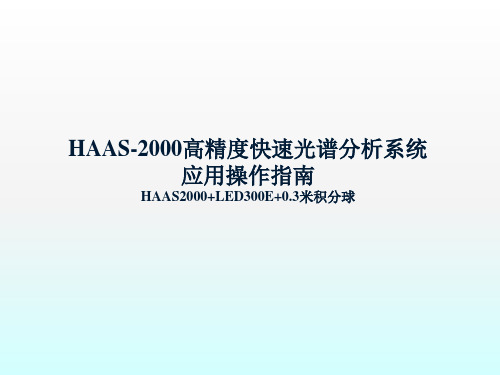
2. 内壁涂层主要材料选用诗贝 伦R98高反射涂层,采用特 殊工艺喷涂,不易脱落,化 学稳定性好,日久不易泛黄。
0.3米积分球(诗贝伦高反射率涂层)
侧边开孔:测试时, 此圆形盖子可以取下, 用于放置LED夹具。
8芯航空插头:连接 积分球内部的LED灯 座,用于定标及普通 LED的测试。
4. RS-232通讯接口:用于连接计算机 COM口。
0.3米积分球(诗贝伦高反射率涂层)
结构:
1. 此积分球直径为0.3米,由两 个半球组成 。
2. 积分球内的LED灯座以倾斜 45°的方式固定,用于放置 普通小功率LED ;同时积分 球侧边开孔,用于满足各类 power LED的测试。
主要特点:
step5
step6
step7
step8
4. HAAS-2000 光纤的安装步骤(3)
step8
5. HAAS2000 电源线的连接
电源线
6. LED300E RS232数据线连接
RS232数据线
7. LED300E 电源线的连接
电源线
8. 积分球内部灯座 航空插头连接
积分球内部灯座8芯航空插头 对积分球定标或使用球内插座测试时连接
4). LED白光分类操作
➢ 点击 添加
➢ 在输入对话框中填写 分类名称。
➢ 点击右图中的添加,根 据需要添加色品坐标(x, y)的组数,坐标值需依 次按顺时针或逆时针方 向输入,不能交叉输入, 输入值直接在界面上修 改,输入完毕后,软件 根据色品坐标值形成一 个封闭的区域
➢ 红色的十字叉标示的被 测LED的色坐标,处在 四边形框内,说明符合
1). 进入操作菜单下的快速光谱仪【定标】,如图所示。
Agilent U2000 系列USB 功率传感器操作和服务指南
环境条件 温度 湿度 海拔高度 污染
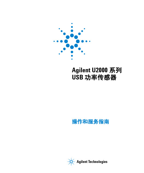
要求 0 °C 至 +55°C (操作时) –30 °C 至 +70 °C (非操作时) 在 40 °C 时最大值为 95% (操作时,无凝结) 在 65 °C 时最大值为 90%(无凝结,在非操作时) 最大值为 4,600 米 (15,000 英尺,操作时) 最大值为 4,600 米 (15, 000 英尺,非操作时) 2级
Agilent Technologies 证明此产品在工厂发货时符合发布的规格。 Agilent Technologies 进一步证明,在美国国家标准与技术研究院校 准工具以及其他国际标准组织成员的校准工具允许的范围内,其校 准测量结果是可跟踪的。
上述保修条款不适用于以下情况:由于购买者维护不当或不合适而 造成的损坏、购买者提供的软件或接口连接、未经授权的修改或误 用、在产品的环境规格以外进行操作或不恰当的现场准备或维护。 没有其他明示或暗示保证。 Agilent Technologies 特别否认对特定目 的适销性、适合性的暗示担保。
警告
“ 警告 ” 标志表示有危险。它要 求在执行操作步骤时必须加以 注意,如果不正确地执行操作或 不遵守操作步骤,则可能导致人 身伤亡。在没有完全理解指定的 条件且不满足这些条件的情况 下,请勿继续执行 “ 警告 ” 标志 所指示的任何不当操作。
ii
U2000 系列操作和服务指南
证明 保修限制 唯一补偿
complies with the essential requirements of the following applicable European Directives, and carries the CE marking accordingly:
海洋光学光谱仪使用方法
海洋光学光谱仪使用方法
海洋光学光谱仪是一种用于研究海洋中光学特性的仪器。
使用光学
光谱仪可以获取海洋中不同波段光的反射率和透过率等信息。
下面介
绍海洋光学光谱仪的使用方法。
一、仪器准备
1. 材料准备:光学光谱仪、计算机、采样瓶和样品收集器。
2. 仪器准备:将采样瓶和样品收集器清洗干净,准备好样品,确保光
学光谱仪能够连接到计算机上。
二、仪器连接
1. 将光学光谱仪连接到计算机上。
2. 启动光学光谱仪软件。
3. 通过软件设置好光学光谱仪的参数,包括光的波段范围、采集时间、光通量、入射角等。
三、样品采集
1. 选择有代表性的海水样品。
2. 用采样瓶收集样品。
3. 将样品倒入样品收集器中。
四、光学光谱仪操作
1. 开启光学光谱仪,确保光路中无杂光和污染。
2. 将样品收集器放入光路中,使其与光学光谱仪接触。
3. 确认光学光谱仪的参数设置正确,并启动数据采集。
4. 采集的数据将通过软件进行图像处理,并生成相应的光谱图。
五、数据分析
1. 利用图像处理软件对光谱图进行分析。
2. 计算反射率和透过率等参数。
3. 利用其他分析方法进一步分析数据。
以上是海洋光学光谱仪的使用方法。
在使用过程中要注意仪器的清洁和光路的稳定,确保数据的准确性和可靠性。
Nanodrop_2000中文操作手册
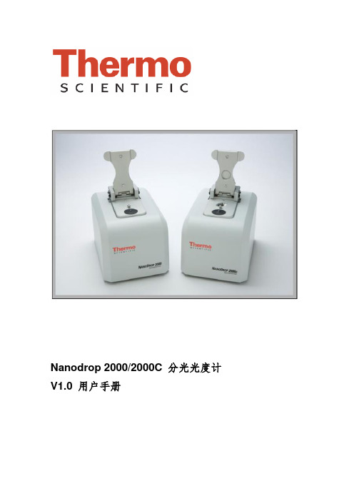
Nanodrop 2000/2000C 分光光度计V1.0 用户手册基因有限公司仪器应用技术支持亲爱的用户,您好!非常感谢您选购我公司代理的仪器。
我们将竭诚为您提供优质的售后服务及免费的专业应用培训。
为了更好地进行仪器的应用培训,我们根据您所选购的仪器特点,将需要您配合准备的工作敬告如下:1. 应用培训内容:仪器操作培训和软件应用培训。
仪器操作培训包括:仪器的操作、维护和仪器使用注意事项。
软件应用培训包括:用户本次所购买的同仪器配套的所有软件的软件应用培训。
2. 培训时间:仪器正式安装调试后,由安装工程师现场培训仪器操作。
3. 应用培训中所需准备的试剂、耗材和仪器均需由用户提供,并在系统培训开始前准备好。
4. 用户签收售后服务工作报告后,基因公司正式的系统培训内容即完成。
您以后在使用的过程中有任何疑问都可以向我们咨询,我们非常乐意为您们解决应用上遇到的问题。
5. 在仪器的使用过程中,无论遇到您认为多么微小或繁琐的问题,请您及时和我们联系,一个及时的通知能节约您的时间,也能帮助我们更好的了解仪器和软件。
6. 联系我们时请您提供:仪器型号、软件名称,版本、错误代码、实验目的、操作系统(98/2k/xp/NT)、维修历史等相关资料。
本守则提的信息仅供参考,本守则包含的所有信息应该是正确和完整的。
如果对本守则中的描述有疑问,请参考厂家的英文操作说明。
如果由于您的不正当使用而对仪器造成损坏或者导致仪器的性能损伤,本公司将不会对此负责。
1.仪器介绍仪器描述Thermo Scientific NanoDrop 2000/2000C分光光度计可以检测0.5-2ul的样本,而且检测是非常高的准确性和重复性。
ND2000C分光光度计不仅提供了NanoDrop 样品保留专利技术的便利性,也可以使用传统的比色皿来进行样本检测。
样本保留系统应用了表面张力来把样本保留在两根检测光纤中间,这使得仪器可以检测较高浓度的样本而不用稀释。
海洋光学HR2000+光谱仪介绍

HR2000+微型光纤光谱仪监测LS-1开启时的状态这是LS-1卤钨灯光源通电后的数据,该数据是由HR2000+在每隔2毫秒的时间间隔内采集到的。
HR2000+能够在1秒钟内采集1000幅光谱。
在这个测量系统中,DH2000氘灯光源发出的光通过光纤射入CUV-10样品池。
从样品池另一端出射的光通过另一根光纤,进入到HR2000+光谱仪。
■动态电子控制HR2000+光谱仪集成了A/D转换器、可编程电子元件、高分辨率的光学平台。
这个具有革新性的光谱仪是迄今为止采样速度最快的产品,且光学分辨率(FWHM)能高达0.035nm。
■1000全光谱/秒HR2000+利用了2MHz的A/D转换器,在使用USB2.0接口时,获取和传输一幅全光谱数据到内存时间能达到1毫秒。
■可编程微处理器HR2000+内置了一个可编程的微处理器,可以灵活地控制光谱仪和附件。
通过一个30针的连接器,就能够在软件上实现各种操作。
例如,控制外部的光源,创建进程和程序,获取外部仪器的数据。
HR2000+提供了10个用户可编程数据I/O口跟外部器件通信;一个模拟输入口和一个模拟输出口;一个脉冲激发器,用于激发其它仪器。
(对I/O编程,需要SpectraSuite 光谱操作软件)■“HR”光学平台HR2000+响应范围为200-1100nm,但是具体的光谱范围,分辨率和灵敏度取决于”HR”光学平台的配置。
一般配置包括,光栅,波长范围,反射镜膜层,探测器组件,入射数值孔径。
在实际应用系统中,我们提供了数百种的附件,以便您更好地选择。
■高分辨率的应用HR2000+应用于快速反应测量和高分辨率要求系统中是非常理想的。
例如蛋白质动态检测。
对于化学物质分析或颜色测量,USB4000可能更符合您的需要。
■即插即用操作HR2000+通过USB2.0或串口,可跟PC,PLC或其它嵌入式处理器进行通信。
当通过USB口跟计算机连接时,HR2000+不需要电源,因为光谱仪直接由计算机供电。
海洋光学usb200+参数

海洋光学(Ocean Optics)的USB200+系列光谱仪是一款便携式、USB接口的光谱测量设备。
以下是USB200+系列光谱仪的一些主要参数:
1. 波长范围:通常覆盖可见光和近红外光谱区域,具体波长范围可能因不同型号而异。
2. 分辨率:光谱分辨率通常较高,能够捕捉到光谱中的细微变化。
3. 光谱采样间隔:决定了光谱数据点的密度,通常以纳米(nm)为单位。
4. 动态范围:测量光强度的最大和最小值之间的范围。
5. 积分时间:光谱仪积分光信号的时间,可以调整以平衡信噪比和测量速度。
6. 光谱带宽:指光谱仪能够测量的光谱宽度或范围。
7. 探测器类型:通常使用硅(Si)或铟镓砷(InGaAs)等类型的探测器,取决于测量的波长范围。
8. 光谱格式:输出的光谱数据格式,如波长-强度对、
ASCII文本等。
9. 数据传输速率:通过USB接口传输数据的速度。
10. 尺寸和重量:便携式设计,方便携带和现场测量。
11. 电源要求:通常需要USB供电,但也可能需要外部电源。
12. 软件支持:通常附带光谱分析软件,用于数据采集、处理和分析。
需要注意的是,具体的参数可能会因不同的USB2000系列型号而有所不同。
为了获得最准确和最新的参数信息,建议直接访问海洋光学的官方网站或联系其技术支持部门。
此外,海洋光学可能会不断更新其产品,因此建议查看最新的产品手册或数据表。
开题译文
USB4000光纤光纤光谱仪安装和操作手册1 产品概述海洋光学USB4000光谱仪,是我们下一代、高性能的微型光纤,从我们热门的USB2000模型设计,包括先进的检测器和功能强大的光谱高速电子。
新功能包括高速快门、3648元电子探测器、Linux,Macintosh和Windows操作系统的接口功能。
该USB4000的响应是从200-1100 nm,但在特定的范围和分辨率取决于你的光栅狭缝的选择。
USB4000是光谱仪完美的应用,增强电子设备高分辨率和快速整合时代需要。
编入每个USB4000上的内存芯片上的数据包括波长校准系数和线性系数。
每个光谱仪独有的序列号。
我们的光谱仪操作软件简单地从光谱仪读取这些值- 热交换的功能,使光谱仪与计算机之间连接。
USB4000光谱仪通过USB端口或串口连接到电脑。
当连接光谱仪通过USB2.0或1.1,获得了来自电脑主机的电源,省去了外接电源。
在USB4000中,像所有的USB设备,可以控制我们的SpectraSuite 一个完全模块化的,基于Java的光谱软件平台Windows 、Macintosh和Linux操作系统上运行的软件。
1.1海洋光学USB4000光纤光谱仪特点:TCD1304AP探测器:它的响应从200至1100 nm,具体范围和分辨率取决于你的光栅和狭缝的选择,它的灵敏度高达130光子/计数在400 nm;60光子/计数在600 nm〜0.3光学分辨率(半峰宽)各种可用的光学•14光栅•6狭缝宽度•3探测器涂料•6光学过滤器积分时间从10微秒到65秒的嵌入式微控制器,使所有工作参数的编程控制和独立操作。
高达480Mbps的USB2.0(高速)和12Mbps(全速),RS232115K波特率,多种通信标准,数码配件(SPI和I2C)的EEPROM存储。
波长校准系数,线性修正系数,绝对辐射校正(可选),低功耗只有250毫安@ 5 VDC,16位,3MHz 的A / D转换,5触发模式,2触发其他设备可编程频闪信号,22针连接器,用于连接到外部产品独立操作的可编程CE认证。
usb2000光谱仪使用手册

USB2000光谱仪使用手册1. 简介USB2000光谱仪是一种高精度、高分辨率的光谱仪器,广泛应用于实验室研究和工业生产领域。
它可以用于光谱分析、荧光测量、光学光谱成像等领域,具有极高的灵敏度和稳定性。
2. 使用前准备在使用USB2000光谱仪进行实验前,需要首先完成以下准备工作:- 将USB2000光谱仪连接至计算机,安装相应的驱动程序和软件。
- 确保光谱仪所处的实验环境光线充足、稳定。
- 检查光谱仪的各个部件是否正常,如接口、光源、探测器等。
3. 光谱获取方法USB2000光谱仪可以通过以下几种方法获取光谱数据:- 单次扫描:通过设置光谱仪扫描的起始波长和终止波长,进行一次完整的光谱扫描。
- 连续扫描:在实验中需要连续监测变化的情况下,可以设置光谱仪进行连续扫描,实时获取光谱数据。
- 多点采样:在不同位置进行多次扫描,获取不同位置的光谱数据,用于分析样品的均匀性和变化。
4. 数据分析和处理获取到光谱数据后,需要进行相应的数据分析和处理。
可以使用USB2000光谱仪配套的软件,也可以使用其他光谱分析软件进行处理。
常见的数据分析方法包括:- 基线校正:对光谱数据进行基线校正,去除背景信号干扰,提高信噪比。
- 波长校正:根据实际情况对光谱仪的波长进行校正,确保数据准确性。
- 峰识别:识别光谱数据中的峰值和谷值,分析样品中的特征成分和性质。
5. 个人观点和理解USB2000光谱仪作为一种先进的光谱分析设备,具有高精度、高分辨率的优点,可以广泛应用于材料科学、光电子学、生物医学等领域。
在实际使用过程中,需要根据实验需求和样品特性合理操作和数据处理,才能充分发挥USB2000光谱仪的优势。
总结通过本文对USB2000光谱仪的使用手册进行全面介绍,希望读者能够更深入地了解和掌握这一先进仪器的操作方法和数据处理技巧。
在实际应用中,要注意仪器的保养和维护,保证数据准确性和实验稳定性,为科研和生产工作提供可靠的数据支持。
【推荐下载】海洋光学PC2000 光谱仪经优化后即将全面恢复生产和交货
海洋光学PC2000 光谱仪经优化后即将全面恢复生产和交货
PC2000光谱仪经过优化终于又和大家见面了, 现在可以按正常交货期大约3周交货了!
海洋光学PC2000光谱仪经过优化终于又和大家见面了, 现在可以按正常交货期大约3周交货!
PC2000 即插式光谱仪
PC2000即插式光谱仪是一个低成本、2048像元线阵CCD光谱仪,配置集成在一块半1MHz ISA总线的A/D转换器上。
这种混合式的光谱仪-A/D结构易于集成插入到计算机的ISA插口上。
预配置的PC2000售价只有$1,999,包括一个主通道光谱仪及集成的ISA总线
A/D转换器。
当然客户也可以订制更多的光谱仪通道,可以是ISA总线或者PCI总线式的,副通道数最多可以扩展至7个,每个通道仅需$799。
每个通道都有各自的光学部件及探测器。
PC2000使用相同的高灵敏度探测器及光学设计,有别于我们的S2000微型光纤光谱仪设计。
类似于S2000,PC2000的光谱响应范围是200nm-1100nm,通过
SMA905可以耦合到一个光纤连接的光源,探头,化学传感器及其它附件上。
通过与其它组件、附件等的连接配套,用户可以方便的搭建不同的光谱仪系统,来满足不同的应用要求。
多通道系统
PC2000的多通道扩展能力,可以用来方便的扩展测量波长范围,多通道取样测量。
安装及操作简单明了:通过数据线连接主通道及其它副通道。
这些副通道通过电。
olympus光谱仪dpo-2000说明书
olympus光谱仪dpo-2000说明书Olympus光谱仪DPO-2000是一款先进的光学仪器,它能够对各种光谱进行精确的测量和分析。
该仪器由Olympus公司设计和生产,采用了先进的技术和创新的功能,为用户提供了高质量和高效率的光谱分析解决方案。
Olympus光谱仪DPO-2000具有多种功能和特点,使其成为专业科研、医学和工业领域中不可或缺的仪器之一。
首先,它具有宽波长范围,能够覆盖从紫外线到近红外线的光谱范围,提供了更广泛的应用领域。
其次,它具有高分辨率和高灵敏度,能够准确地测量微弱的光信号,并对光谱进行精确的分析和解读。
此外,该仪器还具有快速的扫描速度和数据采集率,使用户可以快速获得光谱信息。
Olympus光谱仪DPO-2000还具有易于操作和使用的优点。
它采用了直观的用户界面和简单的操作步骤,使用户可以轻松地进行光谱测量和分析。
此外,它还配备了先进的数据处理和分析软件,可以自动进行数据处理和生成报告,提高了工作效率。
除此之外,该仪器还具有良好的可靠性和稳定性,能够长时间稳定地工作,并保持高质量的光谱测量。
Olympus光谱仪DPO-2000的应用范围非常广泛。
在科学研究领域,它可以用于分析和研究材料的光谱特性,以及探索其在化学、物理和生物学等领域中的应用。
在医学领域,它可以用于诊断和治疗的光学特性的测量,例如医学成像和光学生物学研究。
在工业领域,它可以用于检测和分析材料的光学特性,例如颜色测量和光学表面处理。
综上所述,Olympus光谱仪DPO-2000是一款功能强大、易于操作和广泛应用的光谱分析仪器。
它的高分辨率、高灵敏度和宽波长范围使其成为科研、医学和工业领域中不可或缺的仪器之一。
该仪器不仅能够满足用户对光谱测量和分析的需求,还能提供高质量和高效率的解决方案,为用户的工作带来极大的便利和效益。
无论是在科学研究、医学诊断还是工业应用中,Olympus光谱仪DPO-2000都能够为用户提供可靠的光谱分析和数据处理解决方案,在相关领域中发挥重要作用。
photonview软件使用说明书
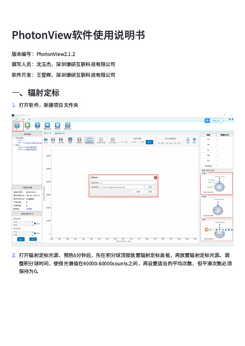
PhotonView软件使⽤说明书版本编号:PhotonView2.1.2撰写⼈员:沈⽟杰,深圳谱研互联科技有限公司软件开发:王登辉,深圳谱研互联科技有限公司⼀、辐射定标1.打开软件,新建项⽬⽂件夹2.打开辐射定标光源,预热5分钟后,先在积分球顶部放置辐射定标盖板,再放置辐射定标光源。
调整积分球时间,使得光谱值在40000-60000counts之间,再设置适当的平均次数,但平滑次数必须保持为0。
3.把辐射定标光源的Shutter开关拨动到中间,内部挡⽚挡住光源,此时光谱曲线⼏乎为0,。
点击“暗背景”按钮,存储暗背景,此时按钮变成“扣暗光谱”字样。
4.把辐射定标光源的Shutter开关拨动到OPEN⼀侧,再次打开光源,再依次点击“保存S0”、“计算”、“保存”等按钮,完成辐射定标,此时波段设置组件激活。
点击“数据表”,可以查看到辐射定标相关数据。
5.辐射定标完成后,关闭并取下光源,取出辐射定标盖板。
对应功率为μw,⾮紫外光,短时间观察对眼睛⽆伤害。
激光器使⽤前,最好预热5分钟,使得光谱值更稳定。
三、PLQY测量特别注意:由于激光器波⻓尖峰很窄,平滑次数会⼤⼤降低激光器尖峰,严重影响测量精度,在进⾏PLQY测量时光谱仪平滑次数只能为0。
PLQY测量分为三个步骤,分别命名为A、B、C,对应得到La、Lb、Pb、Lc、Pc共计5个变量数据,根据公式计算得出PLQY。
1.设置激光器强度在测试开始前,盖住顶部样品⼝,调节激光器强度,使得激光器光谱强度值在50000-60000counts之间。
积分时间、平均次数和平滑次数,通常保持和辐射定标⼀致,也可以按需调整。
2.存储暗背景关闭激光器,点击“暗背景”,存储当前暗背景,此时光谱曲线可在原始光谱、光功率分布和光⼦分布三个模式下任意切换。
该步骤⼀定需要操作,否则⽆法激光操作步骤。
下⾯对三个步骤分别进⾏光谱数据测量。
3.步骤A。
打开激光器,观察到激光器光谱,在操作步骤位置的步骤A选项下,点击“确定”按钮,右侧显⽰出La数值。
海洋光学USB2000+光纤光谱仪的系统性偏差分析
信息科学
光谱仪关键性能进行定量分析。试验结果表明USB2000+光谱仪在辐射定标准确性、响应线性度、暗电流漂移
等方面均存在系统性偏差,并最终导致采集到的数据发生明显偏差。本文针对这些问题,进一步提出了提高海洋
光学USB2000+测量精确度的方法,以此提高数据质量。
关键词:海洋光学USB2000+ ASD FieldSpec4光谱仪 系统性偏差 定量分析 定标
①基金项目:国家级,国家自然科学基金青年基金(项目编号:Y8J7180526)。 作者简介:杨珂圳(1995—),男,硕士,研究方向为高光谱遥感数据处理、卫星定标。 张鹏(1988—),女,博士,助理研究员,研究方向为利用局部倾角的地震成像研究。 通信作者:姜亢(1984—),男,博士,副研究员,研究方向为图像分析与处理。E-mail:jiangkang@。
Laboratory of Technology in Geo-spatial Information Processing and Application System , Aerospace Information Research Institute, Chinese Academy of Sciences, Beijing, 100190 China; 3.University of
Chinese Academy of Sciences, Beijing, 100049 China) Abstract: Ocean Optics USB2000+ is a widely used miniature optical f iber spectrometer in many research f ields. However, we found that there are systematic deviations in radiation calibration, linearity, etc. in the measurement and research using this spectrometer. Based on this, we used the standard instrument ASD FieldSpec4 spectrometer as a benchmark, gave the analysis method of systematic deviation, and conducted a large number of comparative research experiments to quantitatively analyze the key performance of the USB2000+ spectrometer. The results show that the USB2000+ spectrometer has systematic deviations in radiation calibration accuracy, response linearity, dark current drift, etc., and eventually leads to obvious deviations in the collected data. In response to these problems, this paper proposes methods to improve the measurement accuracy of Ocean Optics USB2000+ to improve data quality. Key Words: Ocean Optics USB2000+; ASD FieldSpec4; Systematic deviation; Quantitative analysis; Calibration
【推荐下载】海洋光学将在CIOE2008展示其完整的LED在线测量解决方案
海洋光学将在CIOE2008展示其完整的LED在线测量解决方案
新华美通讯凭借十余年的光谱学开发和应用经验,2008年9月,海洋光学正式推出完整的LED 在线测量解决方案,不仅为LED 工业提供具有极高性能的色坐标在线测量模块,同时也提供各种高精度离线LED 分析手段,可以快速精确地得到色度,辐射度,以及光度数据。
新华美通讯凭借十余年的光谱学开发和应用经验,2008年9月,海洋光学正式推出完整的LED 在线测量解决方案,不仅为LED 工业提供具有极高性能的色坐标在线测量模块,同时也提供各种高精度离线LED 分析手段,可以快速精确地得到色度,辐射度,以及光度数据。
本次参展的产品将包括Jaz、QE65000、USB2000+ 等型号微型光纤光谱仪,LED 在线测量配置、LED 离线测量配置、薄膜厚度测量、采样附件(反射,荧光测量等)、光源(紫外到近红外)、光纤、探头和其它光学器件。
海洋光学的专家们将一直驻留展会现场,为所有的参观嘉宾提供技术建议和基于光纤光谱技术的解决方案。
第十届中国国际光电博览会2008年9月6-9日深圳会议展览中心海洋光学展位号:B009
关于海洋光学
海洋光学的产品在医学和生物研究、环境监测、科学教育、娱乐照明及显示等领域应用广泛,公司隶属豪迈国际有限公司。
豪迈国际是国际电子、安全和环境技术市场。
海洋光学USB2000+光纤光谱仪介绍
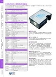
USB2000+微型光纤光谱仪USB2000+微型光纤光谱仪内置了2MHz 的A/D 转换器,可编程电子元件,2048像元的CCD 阵列和USB2.0接口。
USB2000+是迄今为止运行速度最快的光谱仪,它的光谱采集速度能达到1ms。
■动态电子控制USB2000+光谱仪集成了A/D 转换器、可编程电子元件、高分辨率的光学平台。
这个具有革新性的光谱仪是迄今为止采样速度最快的产品。
■1000全光谱/秒USB2000+利用了2MHz 的A/D 转换器,在使用USB2.0接口时,获取和传输一幅全光谱数据到内存时间能达到1毫秒。
■可编程微处理器USB2000+内置了一个可编程的微处理器,可以灵活地控制光谱仪和附件。
通过一个20针的连接器,就能够在软件上实现各种操作。
例如,控制外部的光源,创建进程和程序,获取外部仪器的数据。
USB2000+提供了10个用户可编程数据I/O 口跟外部器件通信;一个模拟输入口和一个模拟输出口;一个脉冲激发器,用于激发其它仪器。
(对I/O 编程,需要SpectraSuite 光谱操作软件)。
■模块化设计的光学平台USB2000+响应范围为200-1100nm,但是具体的光谱范围,分辨率和灵敏度取决于"USB"光学平台的配置。
一般配置包括,光栅,波长范围,反射镜膜层,探测器组件,入射数值孔径。
在实际应用系统中,我们提供了数百种的附件,以便您更好地选择。
■即插即用操作USB2000+通过USB2.0或串口,可跟PC,PLC 或其它嵌入式处理器进行通信。
当通过USB 口跟计算机连接时,USB2000+不需要电源,因为光谱仪直接由计算机供电。
当通过串口连接到计算机时,USB2000+需要额外的电源供电(没有包含)。
每个光谱仪都有唯一的数据参数存储在内存中。
在每次使用光谱仪时,软件都会将这些参数读取到计算机中。
海洋光学usb2000

海洋光学usb2000海洋光学USB2000:揭秘海洋科学领域的利器导语:海洋是地球上最广阔的领域之一,对于人类来说,了解海洋的秘密是一项重要的任务。
而海洋光学则是研究海洋中光的传播、相互作用和探测的学科。
在海洋光学研究领域中,USB2000是一种常用的光谱仪器,本文将介绍海洋光学USB2000的原理、应用以及在海洋科学研究中的重要性。
一、USB2000的原理及特点USB2000是美国Ocean Optics公司生产的一种小型光谱仪器,它采用了USB接口,具有紧凑、便携和易于使用的特点。
USB2000的核心部件是光纤光谱仪,它能够将光信号转换成电信号,并通过软件进行处理和分析。
USB2000可以测量的光谱范围广泛,从紫外到可见光、近红外都能涵盖,适用于各种不同的海洋光学研究。
二、USB2000在海洋光学研究中的应用1. 测量水体光学特性:海洋光学研究中,测量水体的吸收、散射和透射特性是非常重要的。
通过使用USB2000,可以测量水体中不同波长的光的强度,进而研究水体中溶解有机物、悬浮颗粒和藻类等对光的吸收和散射特性,从而了解水体的光学特性。
2. 监测海洋生物光学特性:海洋中的生物对光的吸收和发射有着独特的光学特性。
USB2000可以用于测量不同生物体如浮游植物和浮游动物的光谱特征,从而研究它们的生理状态、生物量和种类等信息。
此外,USB2000还可以通过测量光合作用的光谱特征,推测海洋中的生物生产力。
3. 研究海洋底质特性:海洋底质是海洋光学研究中的一个重要方面。
USB2000可以通过测量水下底质反射光的光谱特征,研究底质的组成、颗粒大小和沉积物的类型等信息。
这对于海洋地质、沉积学和环境监测等领域具有重要意义。
4. 探测水下光学通信信号:水下光学通信是一种新兴的通信方式,在海洋科学研究和海洋工程领域具有重要应用。
USB2000可以用于测量水下光信号的强度和波长分布,评估光信号在水中的传播损耗和衰减情况,为水下通信系统的设计和优化提供重要参考。
usb2000 校准波长
usb2000 校准波长USB2000是Ocean Optics公司生产的一款光谱仪,具有广泛的应用领域。
校准波长是指在使用USB2000进行光谱测量时,需要对仪器进行波长校准,以保证测量结果的准确性和可靠性。
波长校准是指通过比较仪器测量的光谱信号和已知波长的标准光源的光谱信号,来确定仪器的波长刻度。
在进行波长校准时,需要使用具有已知波长的标准光源,如氢氖灯或氩灯。
通过将标准光源的光信号输入到USB2000中,测量得到的光谱信号与已知波长的标准光源的光谱信号进行比较,可以确定USB2000的波长刻度。
波长校准对于USB2000的光谱测量非常重要。
在实际应用中,不同的光谱测量需要使用不同的波长范围和精度。
通过进行波长校准,可以确保USB2000在不同波长范围内的测量结果准确可靠。
进行波长校准时,需要注意以下几点。
首先,要选择适当的标准光源,并确保其具有准确的波长刻度。
其次,要按照厂家提供的操作指南,正确连接和设置USB2000和标准光源。
在进行波长校准时,应保持光源和USB2000的稳定,避免干扰因素对波长校准结果的影响。
最后,在进行波长校准后,应进行验证和确认,确保校准结果准确可靠。
除了波长校准,USB2000还可以进行其他参数的校准,如灵敏度校准和暗电流校准。
灵敏度校准是指校准USB2000的光电转换效率,以确保测量结果的准确性。
暗电流校准是指校准USB2000在无光照条件下的电流输出,以减小暗电流对测量结果的影响。
在实际应用中,校准波长是保证USB2000测量结果准确性的重要环节。
只有进行了准确的波长校准,才能得到可靠的光谱测量结果。
因此,对于使用USB2000进行光谱测量的用户来说,掌握波长校准的方法和技巧是非常重要的。
USB2000的校准波长对于保证其光谱测量结果的准确性和可靠性至关重要。
通过正确选择标准光源,按照操作指南进行校准操作,并进行验证和确认,可以确保USB2000在不同波长范围内的测量结果准确可靠。
USB2000+可见光纤光谱仪
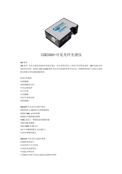
USB2000+可见光纤光谱仪-优势 *即插即用的设计 *友好的用户交互界面 *无需外部电源供电 *可满足多种应用 *可根据不同用户需求订制波长范围和分辨率
8 位板载可自定义数字 GPIO 口 无 4种 有
Windows, Mac, Linux USB 2.0,RS-232 SPI(3-wire); I2C 集成电路
焦距 入射孔径 光栅选择 光纤连接器
物理参数 外型尺寸 质量 电学参数 功耗 数据转换速度
USB2000+
线阵 CCD 探测器 200-1100nm 2048 14um×200um ~62 500 电子 400nm 处:75 光子/counts 600nm 处:41 光子/counts
最大值 650nm(取决于光栅) ~0.3-10.0nm(FWHM) 250:1 16 位 50 RMS counts 1300:1
10 微秒至>60 秒 600nm 处:<0.05% 435nm 处:<0.10% >99.8%
f/4, 非对称交叉式 Czerny-Turner 42mm 入射,68mm 出射 5,10,25,50,100 或 200um 14 种光栅可供选择 SMA 905 单股光纤接口 (0.22 数值孔径)
1 毫秒至 >60 秒 600nm 处:<0.05% 435nm 处:<0.10% >99.8%
【推荐下载】海洋光学发布新一代QE Pro高性能光谱仪
海洋光学发布新一代QE Pro高性能光谱仪
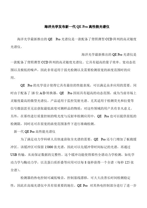
海洋光学最新推出的QE Pro光谱仪是一款配备了背照薄型CCD阵列的高灵敏度光谱仪。
海洋光学最新推出的QE Pro光谱仪是一款配备了背照薄型CCD阵列的高灵敏度光谱仪。
它具有超高的量子效率、宽动态范围以及极低的噪声,因此非常适用于弱光检测以及需要检测很宽的浓度范围时的应用。
QE Pro的光学设计使得它具有最佳的性能表现,可以满足众多应用的需要。
同时由于配备了18位A/D转换器,QE Pro因而具有超高的动态范围,成为当前市场上灵敏度最高的微型光谱仪。
产品适用于监控发射光谱、尤其适用于检测荧光和拉曼等信号微弱甚至无法获取最低浓度可测样品的物质;对这些领域的用户具有非凡意义。
另外,在那些进行质量控制的吸光度与反射率检测应用中,QE Pro也可以提供很低的检测限,同时还可在很宽的浓度范围条件下进行准确检测。
新一代QE Pro高性能光谱仪
为了满足动力学科研人员快速获取全光谱的需要,QE Pro还专门增加了板载缓冲区。
该缓冲区可保留15000张光谱,因此可以先缓冲带时间标记的光谱,再通过USB传输,从而保证数据的完整性。
这个缓冲功能使得那些全谱动力学检测,如化学动力学与酶动力学,以及蛋白质折叠等应用可以每8毫秒获得一个全谱(每秒125张全谱)。
检测器的热电控制可减低噪音,控制基线漂移,可大大改善长时间检测稳定性,因此在高端光谱仪中具有很重要的地位。
QE Pro 对其热电控制部分进行了进一步。
- 1、下载文档前请自行甄别文档内容的完整性,平台不提供额外的编辑、内容补充、找答案等附加服务。
- 2、"仅部分预览"的文档,不可在线预览部分如存在完整性等问题,可反馈申请退款(可完整预览的文档不适用该条件!)。
- 3、如文档侵犯您的权益,请联系客服反馈,我们会尽快为您处理(人工客服工作时间:9:00-18:30)。
海洋光学为USB2000+光谱仪新增触发选项
USB2000+有一个可编程的高速FPGA控制器,22脚接头和8个用户可编程的数字I/O.工作模式包括是正常采集(光谱仪连续地采集光谱)和4种触发模式:
上海2011年8月3日电/美通社亚洲/ -- 海洋光学( OceanOpticsChina )为广受欢迎的USB2000+微型光谱仪增加了新的触发功能,用于提供光谱仪与其它设备间的精确定时和同步。
现在除了正常模式(光谱自由采集)外,共有四种低抖动触发模式可供用户选择。
典型的应用包括同步采集脉冲光源的光谱,在线检测移动样品时,或当传感器达到某个温度水平时的触发光谱采集。
光谱仪的触发功能可以在设备间提供精确的定时。
通过一个脉冲信号触发
USB2000+,使其能够与其它设备同步工作,比如关闭或打开光源、给氙灯发一个脉冲,或起动光谱仪的光谱采集。
当USB2000+工作在外部触发模式,采样系统外的一个事件(如按下一个按钮)的电子触发脉冲,可以启动光谱仪的微秒级精度的光谱采集。
USB2000+有一个可编程的高速FPGA 控制器,22脚接头和8个用户可编程的数字I/O.工作模式包括是正常采集(光谱仪连续地采集光谱)和4种触发模式:
外部软件触发:当光谱仪在正常模式,只有光谱仪收到触发信号时,才把光谱数据传回。
外部硬件水平触发:光谱仪等待在触发输入引脚产生的电平上升沿,然后开始采集光谱,直到该电压返回低电平。
外部同步触发:光谱仪从一个外部触发事件(如一个按钮)开始采集数据直到该触发器下次触发,此时光谱仪停止光谱采集并开始一个新的采集。
积分时间不可以设置,它是两次触发间的时间间隔。
外部硬件边沿触发:光谱仪等待在触发输入引脚。
