USB盒控件开发文档
USB应用与开发
a=val(str) 这段程序代码执行后a的值为整数457
画正弦波
串口操作
右键单击工具箱 空白处,选择部件
双击窗体, 进入程序初 始化程序编
输入 输入 输出 输出 输出 输入 输入 输入 0x38 0 0 0 1 0 0 0 0 0x10
打 下印 载机 线接
口
用C语言开发的第一个程序
让实验板上中间的 LED 发光
#include <mega8> main() {
DDRC = 0x38; PORTC =0x10; while(1); }
RS-232-C传输的数据格式
一帧包含以下信息
一位起始位,以发送一个逻辑“0”表示 n位数据位(n=5,6,7,8),先发送数据最低位 一位奇偶校验位(可有可无) 一位至两位停止位,以逻辑“1”表示 例:画出8个数据位 11110000,无校验位,一 位停止位的时序图。
闲
起
停
始
数
止
置
位
据
位
异步串行通讯的波特率
USB接口特点
稳定、便宜、高速(480Mbits/s) 协议规范(USB1.0 USB2.0) 可通过集线器扩展其接口数量 自带5V电源(在小于500mA的情况下使用) 操作系统的支持(W98以上) 外围设备的支持(例如CP2102)
缺点:协议的复杂性
USB接口开发步骤
1、初步决策
USB
PC机
数据交换
是指美国电子工业协会(EIA)正式公布的标准 标准规定了串口的电气连接方式和数据格式 采用标准的25针接口 PC机上有一个9针接口,是该标准的一个子集
winusb设备的开发方法

winusb设备的开发方法
开发WinUSB设备涉及一些复杂的步骤和概念,需要一定的专业
知识和经验。
以下是开发WinUSB设备的一般步骤和方法:
1. 硬件设计,首先需要设计和制造符合WinUSB标准的硬件设备。
这可能涉及选择合适的芯片、接口和电路设计。
2. 驱动程序开发,WinUSB设备需要相应的驱动程序来与Windows操作系统进行通信。
通常使用微软提供的WinUSB驱动框架
来开发驱动程序。
开发驱动程序需要熟悉Windows Driver Kit (WDK) 和 Windows Driver Framework (WDF)。
3. USB描述符配置,在设备固件中配置USB描述符,以确保设
备能够正确地与Windows系统进行通信。
描述符包括设备描述符、
配置描述符、接口描述符等。
4. 测试和调试,在开发过程中需要进行大量的测试和调试工作,确保设备和驱动程序的稳定性和兼容性。
可以使用微软提供的HLK (Windows Hardware Lab Kit) 进行测试。
5. 证书签名,最终的WinUSB驱动程序需要通过微软的数字签名认证,以确保安全性和兼容性。
这需要申请和获取相应的数字证书。
需要注意的是,开发WinUSB设备需要一定的专业知识和经验,包括硬件设计、驱动程序开发、USB协议等方面的知识。
此外,开发过程中可能会遇到各种问题和挑战,需要耐心和细心地解决。
最好的方法是参考微软官方文档和开发者社区的经验,以及与经验丰富的开发者进行交流和讨论。
java libusb 案例
java libusb 案例摘要:1.Java LibUSB 简介2.Java LibUSB 开发环境搭建3.Java LibUSB 案例:USB 设备通信4.Java LibUSB 案例:USB 设备控制5.Java LibUSB 在实际项目中的应用与前景正文:Java LibUSB 是一款基于Java 语言的USB 设备开发库,它允许Java 程序员通过USB 接口与硬件设备进行通信。
LibUSB 是一款跨平台的USB 设备驱动程序,通过在Java 中调用LibUSB API,开发者可以方便地实现对USB 设备的控制与数据传输。
1.Java LibUSB 简介Java LibUSB 是Java 语言中一个用于操作USB 设备的库。
它基于LibUSB 库,LibUSB 是一款开源的跨平台的USB 设备驱动程序,支持Windows、Linux 和Mac OS 等操作系统。
通过使用Java LibUSB,Java 程序员可以轻松地实现与USB 设备的通信,进行数据传输和设备控制。
2.Java LibUSB 开发环境搭建要使用Java LibUSB 进行开发,首先需要安装Java 开发环境,并配置好Java 库的路径。
然后,需要在项目中引入Java LibUSB 相关的依赖库。
在Linux 和Mac OS 系统中,可以通过包管理器(如Maven 或Gradle)来安装依赖库。
在Windows 系统中,需要下载相应的库文件并添加到项目的类路径中。
3.Java LibUSB 案例:USB 设备通信在Java LibUSB 中,可以通过USB 设备描述符(USB Device Descriptor)获取设备的信息,如设备名称、制造商、产品序列号等。
通过读写USB 设备的端点(Endpoint),可以实现数据的发送与接收。
以下是一个简单的Java LibUSB 设备通信示例:```javapublic class UsbDeviceCommunication {public static void main(String[] args) throws Exception {UsbDevice device = UsbDevice.getUsbDeviceById(0x1234, 0x5678);UsbInterface intf = device.getInterface(0);UsbEndpoint endpointIn = intf.getEndpoint(0x81);UsbEndpoint endpointOut = intf.getEndpoint(0x01);byte[] dataOut = "Hello, USB!".getBytes();endpointOut.write(dataOut);byte[] dataIn = new byte[64];int bytesRead = endpointIn.read(dataIn);System.out.println("Received data: " + new String(dataIn, 0, bytesRead));}}```4.Java LibUSB 案例:USB 设备控制除了数据通信外,Java LibUSB 还支持对USB 设备的控制。
第八章 嵌入式USB接口设备开发实例2
对于低速设备,USB还定义了两种总线操作方
式:控制传输(用于主机设置设备和获取状态) 和中断传输(用于工作信息的传输)。
MC68HC05JB4中的USB模块提供了3个端点,
对USB设备进行调试和检验。
7.2.3 设备的测试
在设备的软件调试过程中,开发者往往需要观
察设备发往主机的数据,包括设备的状态和设 置信息,以及正常工作时发送的数据包等等。 如果开发者需要捕捉USB总线上的信息,必须 使用价格昂贵的专用设备。而如果开发者使用
68HC05JB4,就不用再担心总线信号是否正
常,只需在主机端观察主机接收的数据即可。
USB设备的底层驱动以外,还单独提供了少数 HID设备(如鼠标)的完整驱动,也就是说, 开发者如果想实现一个USB鼠标,是不需要在 Windows98下开发自己的驱动程序的,而如
果想实现一个USB手写板,就必须在通用的底
层驱动基础上开发自己的设备驱动程序。
后一个功能的实现较为困难。USB总线上传递
前一功能与设备的具体工作方式有关,与一般
非USB设备的实现方法大体一致。唯一的区别 是开发者需要预先定义设备所属的类别和使用 的协议。 开发者还应考虑的是主机的工作平台,比如 Windows98/NT、Unix等等,原因是不同的 系统对不同的设备的支持程度不同。
例如在Windows98下,系统除了提供通用的
第八章 嵌入式USB接口设备开发 实例
8.3 USB手写板的设计
USB驱动开发
第17章USB设备驱动USB设备驱动和PCI设备驱动是PC中最主要的两种设备驱动程序。
与PCI协议相比,USB协议更复杂,涉及面较多。
本章将介绍USB设备驱动开发。
首先介绍USB协议,使读者对USB协议有个整体认识。
然后介绍USB设备在WDM中的开发框架。
由于操作系统的USB总线驱动程序提供了丰富的功能调用,因此开发USB驱动开发变得相对简单,只需要调用USB总线驱动接口。
17.1 USB总线协议USB总线协议比PCI协议复杂的多,涉及USB物理层协议,又涉及USB传输层协议等。
对于USB驱动程序开发者来说,不需要对USB协议的每个细节都很清楚。
本节概要地介绍USB总线协议,并对驱动开发者需要了解的地方进行详细介绍。
17.1.1 USB设备简介USB即通用串行总线(Universal Serial Bus),是一种支持即插即用的新型串行接口。
也有人称之为“菊链(daisy-chaining)”,是因为在一条“线缆”上有链接127 个设备的能力。
USB要比标准串行口快得多,其数据传输率可达每秒4Mb~12Mb(而老式的串行口最多是每秒115Kb)。
除了具有较高的传输率外,它还能给外围设备提供支持。
需要注意的是,这不是一种新的总线标准,而是计算机系统连接外围设备(如键盘、鼠标、打印机等)的输入/输出接口标准。
到现在为止,计算机系统连接外围设备的接口还没有统一的标准,例如,键盘的插口是圆的、连接打印机要用9针或25针的并行接口、鼠标则要用9针或25针的串行接口。
USB能把这些不同的接口统一起来,仅用一个4针插头作为标准插头,如图17-1所示。
通过这个标准插头,采用菊花链形式可以把所有的外设连接起来,并且不会损失带宽。
USB正在取代当前PC上的串口和并口。
第17章 USB 设备驱动431图17-1 USB 的四条传输线以USB 方式连接设备时,所有的外设都在机箱外连接,连接外设不必再打开机箱;允许外设热插拔,而不必关闭主机电源。
D12_USB开发使用说明
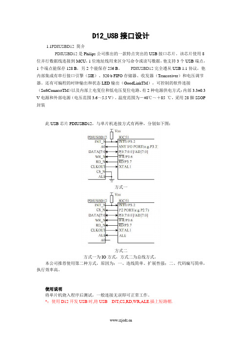
D12_USB接口设计1.1PDIUSBD12简介PDIUSBD12是Philips公司推出的一款特点突出的USB接口芯片。
该芯片使用8位并行数据线连接到MCU,1位地址线用来区分写命令或读写数据,他支持3个USB端点,1个端点能保存128 B,另2个能保存256 B。
PDIUSBD12完全遵从USB 1.1协议,他内部集成有串行接口引擎(SIE)、320 b FIFO存储器、收发器(Transceiver)和电压调节器。
还有可编程的时钟输出和状态LED输出(GoodLinkTM),可控制的软件连接(SoftConnectTM)以及内部上电复位和低电压复位电路。
有2种电源供电方式:内部3.3±0.3 V电源和外部电源(电压范围3.6~5.5 V)。
温度范围为-40℃~+85 ℃,采用28脚SSOP 封装此USB芯片PDIUSBD12,与单片机连接方式有两种,分别如下图:方式一方式二方式一为IO方式,方式二为总线方式。
本公司推荐使用第二种方式,原因为:一、连线简单、扩展性强;二、代码编写简单,执行效率高。
使用说明将单片机烧入程序后测试,一般连接无误即可正常工作。
*:使用D12开发USB时,将USB__INT,CS,RD,WR,ALE.插上短路帽.注:这里说明的代码都是在USB文件夹下:文件夹中分别是上位机, 电脑端驱动,和下位机.实验步骤:(1)将流水灯下位机V8.1中HEX文件烧写入单片机;(2)将开发板用USB线插入电脑的USB口,第一次插入,电脑右下角会提示需要安装驱动;(3)打开hhxyUSBdriver V8.1.rar文件夹:点击进入driver文件夹:其中的hhxyUSBdriver.inf是驱动配置文件,hhxyUSBdriver.sys是驱动文件,电脑提示安装驱动,要选择自己安装驱动(不要选择自动安装),然后将驱动路径定位到这个文件夹,驱动即可正确进行安装。
安装完成以后,可在电脑的设备管理器中看到以下信息:(4)用上位机软件进行测试打开LED流水灯上位机V6.20.rar然后点击进入,得到以下界面进入Realse文件夹,双击MyUsbDeviceTestApp.exe文件:点击打开设备,根据下面提示,正常应显示:设备已打开,失败则显示:未找到设备。
05-USB驱动程序开发

2、USB设备类型 USB设备类型
八、USB设备列举 USB设备列举
在USB规范中有一个非常重要的“动作” USB规范中有一个非常重要的 动作” 规范中有一个非常重要的“ 过程” 这个动作将会让PC PC机知道何 或“过程”。这个动作将会让PC机知道何 USB设备刚接上以及其所含的各种信息 设备刚接上以及其所含的各种信息。 种USB设备刚接上以及其所含的各种信息。 这样,PC机就可以与这个USB设备开始进行 机就可以与这个USB 这样,PC机就可以与这个USB设备开始进行 数据传输的工作了。 数据传输的工作了。这个动作称之为设备 列举(enumeration) (enumeration)。 列举(enumeration)。
7 . USB2.0 的 High-speed 模式支持音频和视频设备 , 可 USB2 High-speed模式支持音频和视频设备 模式支持音频和视频设备, 以保证其固定带宽; 以保证其固定带宽; 8 . 为了适应各种不同类型外围设备的要求 USB 提供了 为了适应各种不同类型外围设备的要求USB 四种不同的数据传输类型:控制传输,Bulk数据传输 数据传输, 四种不同的数据传输类型:控制传输, Bulk数据传输, 中断数据传输,同步数据传输。 中断数据传输, 同步数据传输。 同步数据传输可为音 频和视频等实时设备的实时数据传输提供固定带宽。 频和视频等实时设备的实时数据传输提供固定带宽。 的端口具有很灵活的扩展性。 一个USB 9 . USB 的端口具有很灵活的扩展性 。 一个 USB 端口串 接上一个USB 就可以扩展为多个USB 端口。 USB端口 接上一个 USB Hub 就可以扩展为多个 USB 端口 。 规范 中说,USB可以扩展到127个外设端口 可以扩展到127个外设端口。 中说,USB可以扩展到127个外设端口。
第25章 USB驱动开发
2.设备
struct usb_device_descriptor { __u8 bLength; __u8 bDescriptorType; __le16 bcdUSB; __u8 bDeviceClass; __u8 bDeviceSubClass; __u8 bDeviceProtocol; __u8 bMaxPacketSize0; __le16 idVendor; __le16 idProduct; __le16 bcdDevice; __u8 iManufacturer; __u8 iProduct; __u8 iSerialNumber; __u8 bNumConfigurations; } __attribute__ ((packed));
// 设备描述符长度 // 设备类型 // USB版本号(使用BCD编码) // USB设备类型 // USB设备子类型 // USB设备协议号 // 传输数据的最大包长 // 厂商编号 // 产品编号 // 设备出厂号 // 厂商字符串索引 // 产品字符串索引 // 产品序列号索引 // 最大的配置数量
// 描述符长度 // 描述符类型 // 配置返回数据长度 // 最大接口数 // 配置参数值 // 配置描述字符串索引 // 供电模式 // 接口的最大电流
25.2.2 主机驱动结构
USB主机控制器有3种类型: OHCI:用于SiS和Ali芯片组的USB控制 器。 UHCI:用于Intel和AMD芯片组的USB控 制器。 EHCI:是USB 2.0规范提出的一种控制器 标准,可以兼容UHCI和OHCI。
2.设备驱动结构
ቤተ መጻሕፍቲ ባይዱ
单片机usb程序设计
单片机usb程序设计单片机USB程序设计是一个涉及硬件与软件相结合的技术领域,它允许单片机通过USB接口与计算机或其他设备进行通信。
这种设计在现代电子项目中非常普遍,特别是在需要数据传输和设备控制的应用中。
以下是单片机USB程序设计的基本概念和步骤。
1. 理解USB接口USB(通用串行总线)是一种广泛使用的接口技术,用于连接计算机和各种外围设备。
它支持即插即用和热插拔功能,使得设备连接变得简单快捷。
USB接口有多种类型,包括USB A、B、C等,每种类型适用于不同的设备和应用场景。
2. 单片机与USB的连接单片机要实现USB通信,通常需要一个USB转接芯片或模块,这些芯片提供了USB协议的物理层、数据链路层和传输层的实现。
例如,常见的USB转接芯片有FTDI的FT232、Silicon Labs的CP2102等。
3. 硬件设计在硬件设计阶段,需要考虑单片机与USB转接芯片之间的连接方式,包括电源、数据线、控制线等。
此外,还需要设计电路板的布局,以确保信号的完整性和电磁兼容性。
4. 单片机编程单片机编程是实现USB通信的关键步骤。
这通常涉及以下几个方面:- 初始化程序:在程序开始时,需要对单片机的I/O端口、时钟、中断等进行初始化设置。
- USB协议栈:编写或集成USB协议栈,这是一组实现USB通信协议的软件代码。
- 设备描述符:定义单片机作为USB设备的描述符,包括设备类型、版本号、制造商信息等。
- 端点配置:配置USB端点,端点是数据传输的基本单元,可以是控制端点、数据端点或反馈端点。
5. 设备驱动开发为了使计算机能够识别并正确使用单片机,需要开发相应的设备驱动程序。
驱动程序负责处理操作系统与单片机之间的通信,包括数据的接收和发送。
6. 应用层软件开发应用层软件是用户与单片机交互的界面。
它可以是一个简单的控制面板,也可以是一个复杂的应用程序,用于显示数据、发送指令等。
7. 调试与测试在设计和编程完成后,需要进行调试和测试,确保单片机的USB通信功能正常工作。
usb开发文档
今天有空,开贴讲讲,怎样配合ST提供的库函数理解STM32F102/103的USB模块,以及怎么调用这些库函数来实现基本的USB通信。
题目很大,先只讲讲最简单的应用。
本主题由香水城于2010-12-5 09:03 加入精华分享本文到:帖子: 563积分: 2082专家等级:vigia发表于2010-11-26 16:15 | 只看该作者回复引用返回版面TOP??得分:02楼:1 关于512字节的Packet Buffer在STM32F103的USB模块中有一个RAM区,称为Packet Buffer,共有512字节。
帖子: 563积分: 2082专家等级:vigia发表于2010-11-26 16:18 | 只看该作者回复引用返回版面TOP??得分:03楼:本帖最后由vigia 于2010-11-29 10:13 编辑USB模块中有个Buffer Description Table,这个Table位于512字节的Packet Buffer中,可以在Packet Buffer的任意位置。
USB模块提供一个寄存器USB_BTABLE来设置Buffer Description Table在Packet Buffer的偏移地址。
在库函数中,Define了这个偏移地址:usb_conf.h:#define BTABLE_ADDRESS??(0x00)这意味着Buffer Description Table位于Packet Buffer的首地址。
帖子: 563积分: 2082专家等级:vigia发表于2010-11-26 16:24 | 只看该作者回复引用返回版面TOP??得分:04楼:在Buffer Description Table中的,是所用到的端点的缓存区地址寄存器和缓存区长度寄存器。
所有用到的端点的这两个寄存器都位于这个Table中。
如上所说,由于这个Table位于Packet Buffer的首地址。
驱动设计文档范例

以下是一个驱动设计文档的范例,仅供参考:驱动名称:USB设备驱动一、概述本驱动是为USB设备提供驱动支持的软件模块。
它负责与操作系统进行通信,实现对USB设备的控制和数据传输。
本驱动适用于各种支持USB接口的设备,如U盘、鼠标、键盘等。
二、功能1. 识别USB设备:本驱动能够自动检测并识别连接到计算机的USB 设备。
2. 设备枚举:本驱动能够枚举出连接到的USB设备的详细信息,包括设备类型、制造商、型号等。
3. 数据传输:本驱动能够实现USB设备的数据传输,包括读/写操作。
4. 设备控制:本驱动能够实现对USB设备的控制操作,如打开/关闭设备、设置设备参数等。
三、设计1. 驱动架构:本驱动采用分层架构设计,包括硬件抽象层(HAL)、设备驱动层(DDK)和应用层(APP)。
2. 硬件抽象层:HAL负责与硬件进行通信,实现对硬件的控制和数据传输。
3. 设备驱动层:DDK负责管理设备,实现设备的枚举、控制和数据传输等功能。
4. 应用层:APP负责与操作系统进行通信,实现对USB设备的操作和管理。
四、实现1. 设备枚举:本驱动通过调用系统提供的枚举函数,获取连接到计算机的USB设备的列表。
2. 数据传输:本驱动通过调用系统提供的读/写函数,实现USB设备的数据传输。
3. 设备控制:本驱动通过调用系统提供的控制函数,实现对USB设备的控制操作。
五、测试1. 功能测试:对USB设备的各项功能进行测试,确保功能正常。
2. 性能测试:对USB设备的性能进行测试,包括数据传输速度、稳定性等。
3. 兼容性测试:对不同操作系统和不同硬件平台进行测试,确保兼容性良好。
4. 安全性测试:对USB设备的安全性进行测试,包括数据加密、身份验证等。
六、文档和参考资料1. USB规范:详细描述了USB设备的通信协议和接口规范。
2. 操作系统API:提供了与操作系统进行通信的API函数列表和使用方法。
3. 其他参考资料:包括相关技术文档、教程等。
Android 3.1 USB配件开发之介绍篇
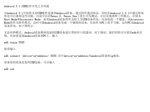
Android 3.1 USB配件开发之介绍篇 从Android 3.1开始将支持USB配件连接到Android设备,通过附件通讯协议,同时在Androexus One上进行开发测试,可以实现两种工作模式,分别为 Host Mode和Accessory Mode,前者Android设备将作为宿主为USB设备供电,比如连接一个键盘,而Accessory Mode将作为附件模式,这时可能Android设备变成一个辅助的设备,比如作为PC上的手写板,这时PC为Android 设备供电,如下图所示: 无论何种模式,Android设备都和连接的USB设备进行类似串口的通讯,对于调试,我们仍然可以使用adb来实 现,比如说连接Android设备到PC上,输入 adb tcpip 5555 接着输入 adb connect <device-ip-address>:5555 其中device-ip-address为android设备的ip地址, 如果你的设备是监听USB连接,可以输入 adb usb
一文入门usb设备的驱动编写方法

一文入门usb设备的驱动编写方法USB设备驱动编写入门USB(通用串行总线)是一种广泛使用的协议,用于在计算机和外围设备之间建立通信渠道。
编写USB设备驱动程序需要对USB规范以及操作系统提供的底层机制有深入的理解。
1. 理解USB规范USB规范定义了设备之间的通信协议、设备类型和描述符格式等方面。
理解规范对于编写符合标准且能够与其他USB设备交互的驱动程序至关重要。
2. 选择操作系统平台不同操作系统对USB设备驱动程序的要求有所不同。
为Windows环境编写驱动程序与为Linux或macOS编写驱动程序具有不同的方法。
了解目标操作系统的特定要求至关重要。
3. 设置开发环境设置开发环境包括安装必要的工具和库。
这可能需要安装USB 开发工具包或编译器。
阅读操作系统的文档以设置正确的环境。
4. 创建USB描述符USB描述符是描述设备功能和配置的数据结构。
驱动程序需要创建这些描述符才能注册设备并向操作系统公开其功能。
5. 实现USB端点USB端点是设备与计算机之间的数据传输通道。
驱动程序需要实现端点处理程序来处理数据传输和控制请求。
6. 处理USB事件驱动程序需要处理各种USB事件,例如设备插入、拔出和配置更改。
实现事件处理程序来响应这些事件并更新设备状态。
7. 使用USB堆栈操作系统提供USB堆栈,为驱动程序提供与底层USB硬件接口的抽象层。
了解USB堆栈的API和功能对于与硬件交互至关重要。
8. 调试驱动程序调试USB设备驱动程序需要专门的工具和技术。
使用调试器、日志记录和分析工具来识别并解决问题。
9. 测试驱动程序在不同环境和条件下全面测试驱动程序至关重要。
执行功能测试、兼容性测试和压力测试以验证驱动程序的可靠性和稳定性。
10. 提交并分发驱动程序开发完成后,需要向操作系统供应商提交驱动程序以进行认证和分发。
遵守供应商的准则并提供必要的文档。
USB盒控件开发文档
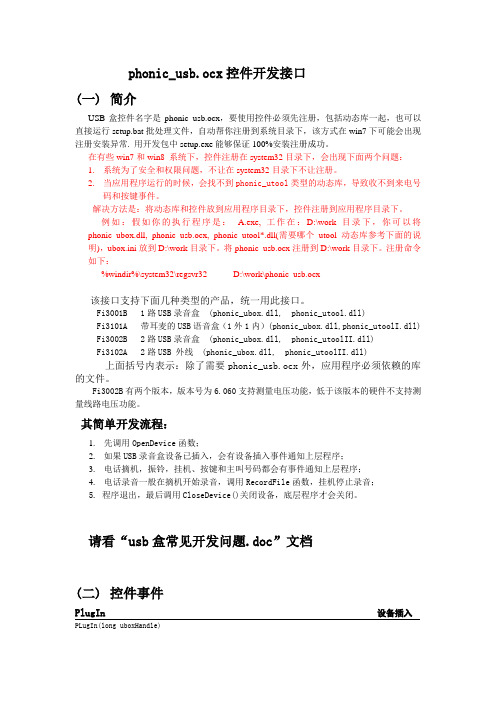
phonic_usb.ocx控件开发接口(一)简介USB盒控件名字是phonic_usb.ocx,要使用控件必须先注册,包括动态库一起,也可以直接运行setup.bat批处理文件,自动帮你注册到系统目录下,该方式在win7下可能会出现注册安装异常. 用开发包中setup.exe能够保证100%安装注册成功。
在有些win7和win8 系统下,控件注册在system32目录下,会出现下面两个问题:1.系统为了安全和权限问题,不让在system32目录下不让注册。
2.当应用程序运行的时候,会找不到phonic_utool类型的动态库,导致收不到来电号码和按键事件。
解决方法是:将动态库和控件放到应用程序目录下,控件注册到应用程序目录下。
例如:假如你的执行程序是: A.exe, 工作在:D:\work目录下,你可以将phonic_ubox.dll, phonic_usb.ocx, phonic_utool*.dll(需要哪个utool动态库参考下面的说明),ubox.ini放到D:\work目录下。
将phonic_usb.ocx注册到D:\work目录下。
注册命令如下:%windir%\system32\regsvr32 D:\work\phonic_usb.ocx该接口支持下面几种类型的产品,统一用此接口。
Fi3001B 1路USB录音盒 (phonic_ubox.dll, phonic_utool.dll)Fi3101A 带耳麦的USB语音盒(1外1内)(phonic_ubox.dll,phonic_utoolI.dll) Fi3002B 2路USB录音盒 (phonic_ubox.dll, phonic_utoolII.dll)Fi3102A 2路USB 外线 (phonic_ubox.dll, phonic_utoolII.dll)上面括号内表示:除了需要phonic_usb.ocx外,应用程序必须依赖的库的文件。
USB设备应用开发套件 для Windows Embedded CE 6.0 用户指南说明书
USB Device Application Kit for WindowsEmbedded CE 6.0User's ManualDigi document reference number: 90000926_A© Digi International Inc. 2008. All Rights Reserved.The Digi logo is a registered trademark of Digi International, Inc.All other trademarks mentioned in this document are the property of their respective owners. Information in this document is subject to change without notice and does not represent a commitment on the part of Digi International.Digi provides this document “as is,” without warranty of any kind, expressed or implied, including, but not limited to, the implied warranties of fitness or merchantability for a particular purpose. Digi may make improvements and/or changes in this manual or in the product(s) and/or the program(s) described in this manual at any time.This product could include technical inaccuracies or typographical errors. Changes are periodically made to the information herein; these changes may be incorporated in new editions of the publication.Digi International Inc.11001 Bren Road EastMinnetonka, MN 55343 (USA)+1 877 912-3444 or +1 952 912-34442Contents1Introduction (6)1.1Features (6)2Requirements (7)2.1BSP requirements (7)2.2Microsoft Windows® CE OS Configuration (7)3Installation (9)4Integration (10)4.1Integration overview (10)4.2Integration process (10)4.3Driver starts (12)5Using the USB Device functionality (13)5.1Serial USB Function Client (13)5.2Mass Storage USB Function Client (17)6Uninstallation (18)3USB Device Application Kit for Windows Embedded CE 6.0 - User's Manual4Conventions used in this manualHere is a list of the typographical conventions used in this manual:StyleNew terms and variables in commands, code, and other input. Style In examples, to show the contents of files, the output fromcommands. In, text the C code.Variables to be replaced with actual values are shown in italics.Style For menu items, dialogs, tabs, buttons, and other controls.In examples, to show the text that you enterMenu name > optionA menu followed by one or more options; for example, File >New.This manual also uses these frames and symbols:This is a warning. It helps solve or avoid common mistakes or problems.This is a hint. It contains useful information about a topic.> This is a host computer session> Bold text indicates what must be entered .> This is a target session > Bold text indicates what must be entered .USB Device Application Kit for Windows Embedded CE 6.0 - User's Manual5AbbreviationsASCIIAmerican Standard Code for Information Interchange CPUCentral Processing Unit ESD Electrostatic DischargeGPIO General Purpose Input/Output OS Operating SystemPC PersonalComputer RAMRandom Access Memory ROOTFSRoot File System TFTPTrivial File Transfer Protocol TTY TeletypewriterUSBUniversal Serial BusUSB Device Application Kit for Windows Embedded CE 6.0 - User's Manual1IntroductionThe USB Device Application Kit is a product that brings the USB Device physical interface to your Digi Development board or JumpStart board.The USB Device Application Kit hardware board connects to the Development or JumpStart board via the USB Application Header and the provided 16-pin flat cable. It basically mounts a USBPHY and USB B female connector.The USB Device Application Kit software contains the driver needed to support the USB DeviceController in a Microsoft Windows® Embedded CE 6.0 OS Design.This User's Manual assumes that the reader is able to create, compile and download a kernel image.1.1FeaturesThe following are the main features of the USB Device Application Kit:•USB 2.0 Full Speed (Low speed not supported)•Board is powered from Development or JumpStart board•Operation modes: serial and mass storage,•±15kV ESD protection6USB Device Application Kit for Windows Embedded CE 6.0 - User's Manual2RequirementsHost System requirementsThe development system has to meet the following requirements:•x86 PC with 500 MHz Pentium III or faster processor; 2 GHz Pentium 4 or equivalent recommended•Microsoft Windows® 2000 Professional with Service Pack 4 or Windows XP Professional with Service Pack 1.•Microsoft Windows® CE 6.0 with Service Pack 1 installed and updates•Serial port•Ethernet network card2.1BSP requirementsDisplay interface support recommended for development purposes, but not required.2.2Microsoft Windows® CE OS Configuration2.2.1Required componentsGo to the Catalog and expand Device Drivers > USB Function > USB Function Clients.Then include this element:USB Function Clients:• Mass Storage• serialWhen using ActiveSync the components from Core OS > CEBASE > Applications – EndUser > ActiveSync must be included into the Windows CE project.Then include this element:ActiveSync:• File SyncFurthermore, the component from Core OS > CEBASE > Communication Services andNetworking > Networking – Wide area Network (WAN) must be included into the Windows CE projectThen include this element:Telephony API (TAPI 2.0):•Unimodem Support7USB Device Application Kit for Windows Embedded CE 6.0 - User's Manual2.2.2Recommended catalog componentsOther recommended networking utilities and services are:Core OS > CEBASE > Communication Services and Networking: • Networking Generalo Network Utilities• Serverso FTP Servero Telnet Server8USB Device Application Kit for Windows Embedded CE 6.0 - User's Manual93 InstallationThis release is installed by executing Setup.exe.The installer wizard will guide you in all required steps.After installation has finished, the following components will be on your PC:%ProgramFiles%\Digi\AppKits\USB_Device_AppKit :• Uninstaller : Executable to uninstall this release.• Release Notes and License Agreements.%_WINCEROOT%\OTHERS\Digi\AppKits\USBFN\src\driver:• Sources of the driver.%ProgramFiles% is an environment variable of your system that provides the path to your Program Files directory (usually C:\Program Files)%_WINCEROOT% is an environment variable of your system that provides thepath to your Microsoft Windows® CE root directory (usually C:\WINCE600).USB Device Application Kit for Windows Embedded CE 6.0 - User's Manual4Integration4.1Integration overviewThe USB Device Application Kit integration described in this chapter assumes that you havealready performed the following steps. These steps are fairly general as they are highly dependant on the customer BSP and the Microsoft Windows® CE version used:Before completing these steps, you will need to have the following applications already installed: •Windows Embedded as described in Chapter 2, and• a BSP corresponding with the hardware that will be used.4.2Integration processThe source code of the driver is also available and can be integrated into a Windows Embedded CE6.0 project as a subproject of it.After you have completely built your Project,it’s time to add a new subproject for theUSB_Device_AppKit Module.Open the Solution Explorer and right-click over the Subprojects. Choose Add ExistingSubproject:Navigate to %_WINCEROOT%\OTHERS\Digi\AppKits\USBFN\src\driver directory and select USBFN.pbpxml:10Now you can see the parameter files and the source files.Right click over USBFN and select Rebuild and then right click over the project and select Make Run-Time Image.The driver build should be rebuilt and included in the final nk.bin image, together with the necessary registry entries.4.3Driver startsVerify that the ns9360_usbfn.dll is inside the new image and that the correct registry entries are placed in the final registry file (reginit.ini).Once the project has been built, download it to the target device and start it up.If you have the USB Device Application Kit connected to the peripheral application header of the target, it should be automatically detected, and you should see a console message similar to thefollowing:[UfnPdd_Init]: Loading USB Device Driver… OK.More information may be shown depending on the debug level established in thedriver.In the console an error message will show up telling that an IOCTL isn’tsupported by the driver. That message can be ignored because that IOCTL onlyreceives some interface information that are not important to the functionality ofthe driver5Using the USB Device functionalityThe USB Device driver provides the functionality upon which the USB function client driverswork. The USB function client drivers implement one or more "functions", each providing adifferent capability to the USB host. In this document we'll see two of these function client drivers: •Serial USB Function Client•Mass Storage USB Function Client5.1Serial USB Function ClientFor both serial profiles standard serial support is necessary within the Windows CE image. Thatcomponent can be found at Core OS > CEBASE > Core OS Services > Serial PortSupport.5.1.1Selecting the ActiveSync profileMake the following change in your USBFN.reg file, you need to uncomment the Serial_Class and comment the rest (“;”).[HKEY_LOCAL_MACHINE\Drivers\USB\FunctionDrivers];"DefaultClientDriver"="Mass_Storage_Class""DefaultClientDriver"="Serial_Class";"DefaultClientDriver"="USBSER_Class"Now you can build the project with the profile selected.Right click over USB_Device_AppKit and select Rebuild and then right click over the project and select Make Run-Time Image.5.1.2Using the profile for ActiveSyncOn the PC side (Host) ActiveSync 4.x or higher must have been installed previously.To use ActiveSync some additional components are necessary. Refer to chapter2.2.1 and include the listed components.If the components have been includedafter building the project a SYSGEN must be done again.After building and deploying successfully the Windows CE image a ActiveSync connection might be necessary to be created on the target side. This is only necessary if more than one serial port is enabled on the target device.Following the steps that are necessary to create on the target side a new direct connection that can be used later by ActiveSync.From the Start menu select Settings -> Network and Dial-up Connections and create a new Direct Connection selecting the Make New Connection option. Select on the next page the serial port that was setup by the system for the USB function interface and close the dialog. The information on the following picture is only an example and that value might be different on other platforms.Now the new connection to use the USB function driver is created. The next step is to use that connection as the default configuration for ActiveSync. Select from the Start menu Settings -> Control Panel and open the PC connection item.Click on the Change button and select the new created direct connection from the list of available connections. Confirm both dialogs with OK and now when connecting the USB function device to the PC ActiveSync should automatically start.5.1.3Selecting the Serial profileMake the following change in your USBFN.reg file, you need to uncomment the Serial_Class and comment the rest (“;”).[HKEY_LOCAL_MACHINE\Drivers\USB\FunctionDrivers];"DefaultClientDriver"="Mass_Storage_Class";"DefaultClientDriver"="Serial_Class""DefaultClientDriver"="USBSER_Class"Now you can build the project with the profile selected.Right click over USB_Device_AppKit and select Rebuild and then right click over the project and select Make Run-Time Image.5.1.4Using the Serial profileWhen using the serial profile no additional components are necessary to expose a serial port to the Host.On the PC side (Host) the standard USB serial driver (usbser.sys) need to be installed. Afterbuilding and deploying successfully the Windows CE image connect the USB cable with the device connector to the target and with the host connector to a PC or Laptop. The first time the host willinstall the corresponding driver and the device will be available for use. In the Device Manager the COM number assigned to the serial port can be found and normal serial communication can beused between the target and the connected PC.5.1.5Installing the USB Serial driver under WindowsIn case the USB serial driver isn’t installed on the used Windows machine the usbser.sys file comes with various versions of Windows. It can be found on Windows XP typically inC:\WINDOWS\Driver Cache\i386\driver.cabWhen the generic serial driver is loaded and the USB device connected to the Windows host with a USB cable, Windows should recognize the generic serial device and ask for a driver. IndicateWindows to find the driver in the folder that contains usbser.inf and usbser.sy s.The usbser.inf is included in the Kit as an example and can be found atC:\Program Files\Digi\AppKits\USB_Device_AppKit\infOn Windows XP, when the generic serial device is first plugged in, the "Found New HardwareWizard" starts up. Select "Install from a list or specific location (Advanced)", on the next screen select "Include this location in the search" and enter the path or browse to the folder containingusbser.inf and usbser.sys.Windows will complain that the Generic Serial driver has not passed Windows Logo testing, but select "Continue anyway" and finish the driver installation. In the "Device Manager" (under"Control Panel", "System", "Hardware") on Windows XP expand the "Ports (COM & LPT)" entry and you should see Generic Serial Port listed as the driver for one of the COM ports.5.1.6Uninstalling the USB Serial driver under WindowsTo uninstall the Windows XP driver for Generic Serial Port, right click on the Generic Serial Port entry in the "Device Manager" and select "Uninstall".5.2Mass Storage USB Function Client5.2.1Selecting the profileMake the following change in your USBFN.reg file that is part of the subproject, you need to uncomment the Mass_Storage_Class and comment the rest (“;”).[HKEY_LOCAL_MACHINE\Drivers\USB\FunctionDrivers]"DefaultClientDriver"="Mass_Storage_Class";"DefaultClientDriver"="Serial_Class";"DefaultClientDriver"="USBSER_Class"Now you can build the project with the profile selected.Right click over USB_Device_AppKit and select Rebuild and then right click over the project and select Make Run-Time Image.5.2.2Using the profileTo use the Mass Storage profile a block device like CF, SD card or USB Memory stick is necessary to make the profile working correctly. Following some examples how some of these block devices need to be added to the Windows CE project.Exposing a USB memory stick from the target to a PC (Host) the components USB Mass Storage Function client, USB Host support and USB Storage class driver are necessary. Using any otherWhen connecting the USB cable to the Host it might take some time till thestorage device is represented .6UninstallationThe USB Device Application Kit can be uninstalled separately using Windows Control Panel.Add or Remove Programs:•USB Device Application Kit for Windows Embedded CE 6.0。
UsbKey开发文档
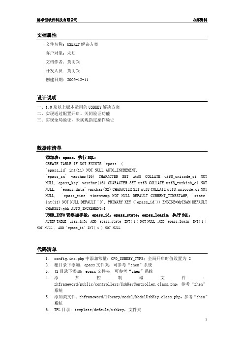
文档属性文件名称:USEKEY解决方案客户对象:未知文档作者:黄明兴开发人员:黄明兴创建日期:2009-12-11设计说明一、1.0及以上版本适用的USBKEY解决方案二、实现通过配置开启、关闭验证功能三、实现全局验证,未实现指定操作验证数据库清单添加表:epass,执行SQL:CREATE TABLE IF NOT EXISTS `epass` (`epass_id` int(11) NOT NULL AUTO_INCREMENT,`epass_sn` varchar(16) CHARACTER SET utf8 COLLATE utf8_unicode_ci NOT NULL,`epass_key` varchar(16) CHARACTER SET utf8 COLLATE utf8_turkish_ci NOT NULL, `epass_data` varchar(32) CHARACTER SET utf8 COLLATE utf8_unicode_ci NOT NULL, `epass_time` timestamp NOT NULL DEFAULT CURRENT_TIMESTAMP, `state` int(11) NOT NULL DEFAULT '0', PRIMARY KEY (`epass_id`)) ENGINE=MyISAM DEFAULT CHARSET=gbk AUTO_INCREMENT=1 ;USER_INFO表添加字段:epass_id,epass_state,eapss_loagin,执行SQL:ALTER TABLE `user_info` ADD `epass_state` INT( 1 ) NOT NULL ,ADD `epass_login` INT( 1 ) NOT NULL , ADD `epass_id` INT( 1 ) NOT NULL代码清单1.config.inc.php中添加常量:CFG_USBKEY_TYPE;全局开启时值设置为 22.根目录下添加:epass文件夹,可参考“zhen”系统3.JS目录下添加:epass文件夹,可参考“zhen”系统4.添加控制器文件:zhframeword/public/controllers/UsbKeyController.class.php,参考“zhen”系统5.添加类文件:zhframeword/library/model/ModelUsbKey.class.php,参考“zhen”系统6.TPL目录:template/default/usbkey,文件夹7.类文件:zhframeword/library/model/ModelUser.class.php;添加方法:checkEpass,用于登时验证key信息8.类文件:zhframeword/library/model/ModelUser.class.php;修改方法:checkUser,添加对checkEpass方法的调用9.类文件:zhframeword/library/Model.class.php;修改方法:executeAction,用于URL请求时执行key验证。
USB开发手册

PowerPC and and the PowerPC logo are trademarks of International Business Machines Corporation, used under license therefrom. Simultaneously published in the United States and Canada.
Chapter 2
Working With USB Device Interfaces 21
Using USB Device Interfaces 21 Accessing a USB Device 22 Definitions and Global Variables 23 The main Function 23 Working With the Raw Device 26 Working With the Bulk Test Device 30 Working With Interfaces 32
Chapter 2
Working With USB Device Interfaces 21
Listing 2-1 Listing 2-2 Listing 2-3 Listing 2-4 Listing 2-5 Listing 2-6 Listing 2-7 Listing 2-8 Listing 2-9 Definitions and global variables 23 The main function 24 Accessing and programming the raw device 26 Releasing the raw device objects 28 Configuring a USB device 28 Two functions to download firmware to the raw device 29 Accessing the bulk test device 31 Finding interfaces on the bulk test device 32 Two asynchronous I/O completion functions 36
Usb开发文档
设备描述表给出了USB 设备的一般信息。
这包括对设备及所有设备配置起全程作用的信息。
一个设备只能有一个设备描述表。
此描述表给出了此配置下的接口数,每个接口可能独立操作。
当主机发出请求要得配置描述表时,所有相关接口与端节点的描述表都被返回。
一个USB 设备有一个或多个配置。
每个配置只有一个或多个接口。
而每个接口又有0 个或多个端节
此描述表在一个配置内给出一个接口的信息。
如果一个配置支持不止一个接口,端节点的描述表会跟
每个接口使用的结点都有自己的描述表,此描述表被主机用来决定每个节点的带宽需求。
每个结点的
下表是类描述符类型表,HID描述符的类型从下表中选择:
在实际应用中,在描述符中可以增加一些厂商的标识。
PID是包标识符,ADDR是主机给USB设备的标识,PID是包标识符,DA TA是数据域,上面的数据长度为
4.3BDT
JM60自带256字节的USB RAM,当不用USB模块时,该RAM可以当作普通RAM使用。
该地址是0x1860~0x195F,偏移地址是00~FF,其中00~1D用于定义端点的BDT(buffer descriptor table)拥有6个不同的端点,数据结构如下图所示:
下图是上述所定义端点buffer的具体结构:。
USB应用程序开发

USB应用程序开发1 前言USB开发跟其他文件设备(如串口)开发一样,难点是找到该USB设备的路径,本文以DDK里src/usb/bulkusb例子为参考,阐述一个非HID的USB调试器软件的开发过程。
2 设备GUID一般设备会有两个GUID, 一个为Class GUID, 在INF文件中,另一个为Device GUID,在SYS文件中。
CreateFile使用的是SYS中的GUID,想得到它有两个办法:1 跟设备的提供者索要。
2在注册表里找,一般在:HKEY_LOCAL_MACHINE/SYSTEM/ControlSet001/Control/DeviceClasses/3 设备路径根据设备GUID,枚举所有USB HOST,找匹配的USB设备,然后获取其路径。
3.1 头文件 usbport.h#define WINVER 0x0500#include <windows.h>#include <setupapi.h>#include <basetyps.h>#include <usbdi.h>#include <initguid.h>#include <stdio.h>#pragma comment(lib,"setupapi.lib")#pragma comment(lib,"hid.lib")#pragma comment(lib,"comctl32.lib")#ifndef BULKUSBH_INC#define BULKUSBH_INC#define BULKUSB_IOCTL_INDEX 0x0000#defineIOCTL_BULKUSB_GET_CONFIG_DESCRIPTOR CTL_CODE(FILE_DEVICE_UNKNOWN, /BULKUSB_IOCTL_INDE X,/METHOD_BUFFERED, / FILE_ANY_ACCESS)#define IOCTL_BULKUSB_RESET_DEVICE CTL_CODE(FILE_DEVICE_UNKNOWN, / BULKUSB_IOCTL_INDE X+1,/METHOD_BUFFERED, / FILE_ANY_ACCESS)#define IOCTL_BULKUSB_RESET_PIPE CTL_CODE(FILE_DEVICE_UNKNOWN, /BULKUSB_IOCTL_INDE X+2,/METHOD_BUFFERED, / FILE_ANY_ACCESS)extern HANDLE open_file(char *filename);extern int GetUsbPath(char *path);extern int WriteUsb(HANDLE hUsb,char *Outbuff, int len); extern int ReadUsb(HANDLE hUsb,BYTE inbuff[],DWORD&nBytesRead,int nToRead);3.2 源文件 usbport.cpp#include "usbport.h"//8a3bf75d-83c7-440e-8276-5ae3f3ea6e77DEFINE_GUID(GUID_CLASS_I82930_BULK,0x8a3bf75d, 0x83c7, 0x440e,0x82,0x76, 0x5a, 0xe3, 0xf3, 0xea, 0x6e, 0x77);BOOL GetUsbDeviceFileName( LPGUID pGuid, char *outNameBuf); HANDLE OpenUsbDevice( LPGUID pGuid, char *outNameBuf); HANDLE OpenOneDevice (HDEVINFO HardwareDeviceInfo,PSP_INTERFACE_DEVICE_DATA DeviceInfoData,char *devName);int GetUsbPath(char *path);int WriteUsb(HANDLE hUsb,char *Outbuff, int len);int ReadUsb(HANDLE hUsb,BYTE inbuff[], DWORD&nBytesRead,int nToRead);/*名称:open_file功能:打开USB设备参数:filename 定义为”PIPE00” pipe name for bulk input pipe on our test board ,”PIPE01” pipe name for bulk output pipe on our test board。
USB开发有关指导说明
MC核心板USB开发源程指导说明.docxFYL dotlfly2004@ 11.2.21 MC核心板经过跳线和USB开发板连接,其中USB开发板芯片使用CH375开发。
由于CH375模块使用的是5V电压,而C8051F020的核心电压是3.3V,但是F020所有的引脚可以设置为漏极开路,利用这个特性,使用了外部加驱动电压的方式实现了3.3V电平和5V电平转换的功能。
注意,成熟产品尽量不要用此种方式,因为如果程序使用不当,可能烧毁MCU,因此本开发板,严禁将I/O配置为推免或者弱上拉的方式。
MC核心板和USB子板的连接是通过P2和P6两个端口,其中P6作为数据端口,P2作为控制端口。
配置如下:/*******************************************************************/ sbit CH375_INT=P2^3;sbit CH375_A0=P2^4;sbit CH375_CS=P2^5;sbit CH375_RD=P2^6;sbit CH375_WR=P2^7;#define CH375_DATA P6/*******************************************************************/ 注意:由于MC核心板比较灵活,功能比较齐全,同时也带来了损坏率比较高的缺点。
在对整套系统不是完全熟悉的情况下,不用对各种跳线或者接线进行擅自修改。
一、开发工具介绍及安装本项目可能用到的开发工具有:KEIL、串口助手、USB助手等。
KEIL安装1.首先安装\mc\开发工具\KEIL4下的keil uvision4.zip,并利用KEIL_Lic.zip进行破解。
2.安装“keilC51v8.02过滤0xfd字符的bug的修正程序中文版本.rar”进行BUG 升级。
3.安装“SiC8051F_uVision.zip”,即C8051F系列单片机库文件。
- 1、下载文档前请自行甄别文档内容的完整性,平台不提供额外的编辑、内容补充、找答案等附加服务。
- 2、"仅部分预览"的文档,不可在线预览部分如存在完整性等问题,可反馈申请退款(可完整预览的文档不适用该条件!)。
- 3、如文档侵犯您的权益,请联系客服反馈,我们会尽快为您处理(人工客服工作时间:9:00-18:30)。
phonic_usb.ocx控件开发接口(一)简介USB盒控件名字是phonic_usb.ocx,要使用控件必须先注册,包括动态库一起,也可以直接运行setup.bat批处理文件,自动帮你注册到系统目录下。
该接口支持下面几种类型的产品,统一用此接口。
Fi3001B 1路USB录音盒 (phonic_ubox.dll, phonic_utool.dll)Fi3101A 带耳麦的USB语音盒(1外1内)(phonic_ubox.dll,phonic_utoolI.dll) Fi3002B 2路USB录音盒 (phonic_ubox.dll, phonic_utoolII.dll)Fi3102A 2路USB 外线 (phonic_ubox.dll, phonic_utoolII.dll)上面括号内表示:除了需要phonic_usb.ocx外,应用程序必须依赖的库的文件。
其简单开发流程:1.先调用OpenDevice函数;2.如果USB录音盒设备已插入,会有设备插入事件通知上层程序;3.电话摘机,振铃,挂机、按键和主叫号码都会有事件通知上层程序;4.电话录音一般在摘机开始录音,调用RecordFile函数,挂机停止录音;5. 程序退出,最后调用CloseDevice()关闭设备,底层程序才会关闭。
(二)控件事件PlugIn 设备插入PLugIn(long uboxHandle)功能:设备插入参数: uboxHandle设备句柄不同USB盒的句柄并不是连续的,但对于2路的盒子,其线路1和线路2的句柄值是相邻的。
PlugOut 设备拨出PlugOut(long uboxHandle)功能:设备拨出。
参数:uboxHandle设备句柄DeviceAlarm 报警DeviceAlarm(long uboxHandle,long param)功能:设备报警,软件要重新启动,否则不能录音和放音。
参数:uboxHandle设备句柄 param如下所示:UBOX_ALARM_CAN_FIND_MIC = 1, 未能找到ubox 的MIC 设备UBOX_ALARM_CAN_OPEN_MIC = 2, 未能打开ubox 的MIC 设备UBOX_ALARM_CAN_OPEN_PLAY = 3, 未能打开ubox 的放音设备UBOX_ALARM_DEVICE_ERROR = 4, 设备故障DeviceError设备错误DeviceError (long uboxHandle)功能:设备错误。
参数:uboxHandle设备句柄,Ring 振铃Ring(long uboxHandle)功能:电话振铃。
参数:uboxHandle设备句柄对于Fi3101A,可以在振铃调用OpenBuzzerSwitch(uboxHandle,true)方法打开蜂鸣器,通知用户来电,在事件HookOff或者RingCancel下调用OpenBuzzerSwitch(uboxHandle,false)关闭蜂鸣器,。
RingStop停振事件RingStop (long uboxHandle)功能:通知应用程序通道停振。
参数:uboxHandle设备句柄,说明:电话机振铃一般是振1秒,停振4秒的一个周期。
RingCancle 振铃取消RingCancel (long uboxHandle)功能:振铃取消,当末次振铃停止超过6秒,则触发此事件。
未接电话可通过该事件判断参数:uboxHandle设备句柄HookOff 摘机HookOff(long uboxHandle, long param1)功能:电话摘机。
参数:uboxHandle设备句柄Param1 = 0,表示电话机摘机Param1 = 6,表示反向摘机,指软件摘机Param1 = 7, 表示正向摘机,指软件摘机Hangup 挂机HangUp(long uboxHandle)功能:电话挂机。
参数:uboxHandle设备句柄HangIng 悬空HangIng(long uboxHandle)功能:线路悬空,线路接口没有连接好。
参数:uboxHandle设备句柄说明:只有Fi3001才有这个功能,如果电话线被拨掉,先触发摘机事件,经过20-30 秒后再触发悬空事件。
CallID事件来电号码CallID(long uboxHandle, LPCTSTR callerNumber, LPCTSTR callerTime, LPCTSTR callerName)功能:通知应用程序来电号码。
参数:uboxHandle 设备句柄,callerNumber号码callerTime 时间callerName 姓名DtmfKey事件用户按键DtmfKey (long uboxHandle, long dtmfCode)功能:通知应用程序用户按键。
参数:uboxHandle设备句柄,dtmfCode是按键键值,需要类型转换 char dtmf = (char) dtmfCode。
PlayEnd放音结束PlayEnd (long uboxHandle)功能:通知应用程序通道放音完毕。
参数:uboxHandle设备句柄,PlayError放音错误PlayError (long uboxHandle)功能:放音错误。
参数:uboxHandle设备句柄,ToneBusy 忙音事件ToneBusy (long uboxHandle)功能:检测到忙音,表示判断对方已经挂机了。
参数:uboxHandle设备句柄,CallOutFinish拨号完成事件CallOutFinish(long uboxHandle)功能:拨号完成参数:uboxHandle设备句柄,Polarity极性检测事件Polarity (long uboxHandle, short lineSign)功能:通知应用程序通知应用程序检测到极性反转。
参数:uboxHandle设备句柄,lineSign 0―――正极,1――反极说明: 极性检测用于外线呼出后对方摘机的判断以及通话过程中对方挂机的判断。
极性反转的功能必须向电信部门另外申请。
(三)函数错误返回值UBOX_ERR_SUCCESS = 0, 操作成功UBOX_ERR_SYSTEM = -1, 系统错误,调用操作系统(windows)的方法时出现错误,错误的详细信息可查看日志文件:UBOX_ERR_DEVICE_NOT_FOUND = -2, 没有这个设备,可能设备已经被拔出UBOX_ERR_INVALID_HANDLE = -3, 不合法的UBOX_HANDLEUBOX_ERR_INVALID_PARAMETER = -4, 不合法的输入参数UBOX_ERR_EXCEPTION = -5, 发生异常UBOX_ERR_INVALID_WORK_MODE = -6, 错误的工作模式UBOX_ERR_UBOX_NOT_OPEN = -7, ubox设备尚未打开UBOX_ERR_CANNOT_CREATE_DIR = -10, 未能创建目录,当指定录音时,如果文件名包含目录路径,则ubox将试图建立相应的目录树。
UBOX_ERR_CANNOT_CREATE_FILE = -11, 未能创建录音文件UBOX_ERR_INVALID_VOICE_CODER= -12, 不支持的语音编码UBOX_ERR_DEVICE_BUSY = -13, 设备忙,当设备已经在录音的时候再次指示其同类型(文件与文件、STREAM与STREAM)的录音,就会返回此错误码(四)控件方法long OpenDevice(short workmode) 初始化语音设备功能:初始化USB设备,设备是否打开成功不是由它决定的,设备打开成功由事件PLugIn通知的。
参数:workmode=0,为录音模式就可以了。
Workmode = 1诊断模式,用于捕获线路信息,供信号分析之用,支持的语音编码方式CODER_PCM Workmode = 2, 配置模式返回: 0成功,错误参照“函数错误返回值”相关方法:CloseDevice()说明:只有Fi3001B配置模式才有用,下面有几个方法要在配置模式下使用。
void CloseDevice() 关闭设备功能:关闭设备;说明:关闭设备是一切的结束。
short GetProductID(long uboxHandle); 获取产品设备号功能:获取产品设备号参数:uboxHandle 设备句柄返回: 对应的产品设备号:1 FI3102A2 FI3002B3 FI3001B4 FI3101Ashort RecordFile(long uboxHandle, LPCTSTR filename, short coder)录音到文件功能:录音到文件参数:uboxHandle 设备句柄filename 文件名coder 录音编码率,支持以下编码:coder =0 CODER_ALAWcoder =1 CODER_PCMcoder =3 CODER_G729coder =20 CODER_SPEEX //这是8倍压缩,安装speexw.exe的插件,播放器就可以播放了coder = 38 mp3编码coder=100 CODER_ULAW一般推荐用CODER_ALAW,mp3和CODER_SPEEX编码。
选择mp3编码格式的,文件名后缀为.mp3,其它格式推荐使用.wav后缀返回: 0成功,错误参照“函数错误返回值”Short StopRecord(long uboxHandle)停止录音功能:停止录音包括对文件和流式录音停止参数:uboxHandle设备句柄返回: 0成功,错误参照“函数错误返回值”Short GetHangThreshold(longuboxHandle)读取悬空门限值功能:读取悬空门限值参数:uboxHandle设备句柄返回:>0 该返回值就是悬空门限值< 0 失败,Short SendDtmf(long uboxHandle, LPCTSTR dtmfNum)拨号功能:发送号码(DTMF)参数: uboxHandle 设备句柄dtmfNum号码串返回: 0成功,错误参照“函数错误返回值”说明: 对于Fi3101A,电话机摘机,软件拨号,要调用软摘机函数,然后调用本函数,拨号声音会到耳麦里输出,号码拨完后,底层会自动软挂机,声音会切换到电话机里,如果电话机摘机,声音自动切换到电话机里,底层会自动软挂机,耳机无声音。
Fi3001B和Fi3002B,必须要先手动摘机,才可以拨号。
对于有软摘机功能的产品(Fi3101A和Fi3102A),直接软件拨号,有可能拨号不成功,拨得太快了,交换机需要时间检测摘机,因此处理方法上层程序需要先软摘机后,延时1-2S钟,然后再调用SendDtmf()函数。
