Schematic Prints
Protel DXP原理图设计基础

2.6.1 导线 导线指具有电气连接关系的一种原理图组件。 1、启动方法一:单击导线工具图标。 方法二:执行菜单命令place-wire。 方法三:在原理图编辑窗口内单击右键,在快捷菜单 中选择wire命令来启动导线命令。 方法四:用快捷键P,W来启动导线命令。 2、画导线步骤 1)在红色连接标记处,单击左键或者ENTER键确定 第一个端点。将光标移到导线的下一个转折点或者 端点,单击左键或者ENTER键确定导线的第二个端 点。
2.3 设置图纸
design-options-document options
2.3.1 设置图纸大小
1、选择标准图纸
2、自定义图纸
3、设置图纸方向和标题栏 orientation:绘制设置landscape;打印设置portrait。 show reference zones:显示边框中的参考坐标。 show border:显示图纸边框。 show template graphics:显示模版的图形、文字及 专用字符串。 border color:设置图纸边框的颜色。 sheet color:设置图纸底色。 change system font:改变图纸 插入汉字或者英文字体。
3、电源端子属性 style:设置电源端子的符号类型。
2.6.6 元件
元件是原理图最基本的组件,在原理图上常 用各种各样的逻辑符号来表示。所有元器 件均来自元器件库,取用之前必须先加载 相应的元件库。 1、启动放置元件命令 方法一,方法二,方法三,方法四和前面一 样。快捷键是p,p。方法五,在库文件管理 器内,双击需要的元器件。方法六,在库 文件管理器中,选中元器件,然后点击 PLACE*.
Schematic:启动原理图设计模块,进行原理 图的绘制工作。 VHDL:启动VHDL程序的编写模块。 PCB:启动印制电路板的设计模块。 schematic library:打开生成和管理元器件库。 PCB library:启动PCB元件封装库的生成模 块。 PCB project:打开或者生成一个印刷电路板 设计项目,在该项目下可以添加原理图的 绘制,PCB的设计,VHDL程序的编写设计。
印刷电路板的设计流程

印刷电路板的设计流程英文回答:Designing a printed circuit board (PCB) involves several steps and processes. It is important to follow a systematic approach to ensure the successful creation of a functional and reliable PCB.1. Requirements Gathering: The first step is to gather the requirements for the PCB design. This includes understanding the purpose of the PCB, the components itwill contain, the size and shape constraints, and any specific electrical or mechanical requirements.For example, let's say I am designing a PCB for a small electronic device such as a smartwatch. I would gather the requirements such as the dimensions of the PCB, the components it needs to accommodate (e.g., microcontroller, display, sensors), and any power or signal requirements.2. Schematic Design: Once the requirements are known, the next step is to create a schematic diagram. This diagram represents the electrical connections between the components on the PCB. It helps in visualizing the circuit and identifying any potential issues or conflicts.Using our smartwatch example, I would create a schematic diagram that shows how the microcontroller, display, and sensors are connected. I would also include any power supply and signal conditioning circuitry.3. Component Selection: After the schematic design, the next step is to select the components that will be used on the PCB. This involves considering factors such as availability, cost, performance, and compatibility with the design requirements.Continuing with our smartwatch example, I would research and select the appropriate microcontroller, display, and sensors that meet the size and performance requirements while staying within the budget.4. PCB Layout Design: With the components selected, the next step is to design the physical layout of the PCB. This involves placing the components on the PCB and routing the electrical connections between them. The layout should consider factors such as signal integrity, power distribution, and thermal management.For our smartwatch PCB, I would use a PCB design software to place the components in an optimal arrangement and route the traces to ensure proper signal flow and minimize interference. I would also consider the power distribution and thermal dissipation requirements to prevent overheating.5. Design Validation: Once the PCB layout is complete, it is important to validate the design before proceeding to manufacturing. This involves performing simulations,testing for signal integrity, and checking for any design errors or issues.In our smartwatch example, I would use simulation tools to verify the performance of the circuit, check for anypotential signal integrity issues, and ensure that the design meets the requirements. I would also perform adesign rule check to catch any errors or inconsistencies.6. Manufacturing and Assembly: After the design is validated, the final step is to prepare the PCB for manufacturing. This involves generating the necessary manufacturing files, such as Gerber files, and working with a PCB manufacturer to produce the actual PCB. Once the PCBs are fabricated, the components are soldered onto the board through assembly processes.Once the PCBs are manufactured and assembled, they can be tested for functionality and reliability. Any issues or defects can be addressed, and the final product can be deployed.中文回答:印刷电路板(PCB)的设计流程包括几个步骤和过程。
Cadence中Schematic,Layout以及Waveform的打印输出及图片文件后处理

1. Plotter的设置将.cdsplotinit文件放置在工作目录或者用户根目录下。
google一下可以找到很多.cdsplotinit文件,但是最简单有效的方法是将Cadence自带的Sample文件拿过来直接使用。
将$opt/cadence/ic5141u6/tools/plot /samples/cdsplotint.sample拷贝至工作目录或者用户根目录,并改名为.cdsplotinit即可。
(cpcdsplotinit.sample ~/.cdsplotinit)打印机的定义可以参照cdsplotint.sample文件,这里给一个例子:EPS|Encapsulated Postscript. \:manufacturer=Adobe: \:type=epsf: \:maximumPages#1: \:resolution#300: \:paperSize="Unlimited" 72000 72000:经过以上设置之后,Plotter一般就算设置好了。
如果这样还有问题,可以添加环境变量setenv CDSPLOTINIT ~/.cdsplotinit (对应的是.cdsplotinit保存在用户根目录,如果.cdsplotinit保存在工作目录,则给出相应路径。
)2.Schematic或Layout打印成PS或EPS输出(1)打开相应的schematic或layout。
(2)在Virtusuo Schematic Editor或Virtusuo Layout Editor中,[Design] - [Plot] - [Submit...], 将调出Submit Plot窗口。
(3)在Area to Plot栏里点击Select按钮,可以选择需要打印的区域,默认是Full Size。
(4)Plot With可以选择header(默认是已选择)和notes。
一般不选。
Altium Designer教程 第2章 原理图编辑器及参数

Altium Designer 教程
2.1 启动原理图编辑器方式
从文件(Files)面板中启动原理图编辑器
启动Altium Designer系统,单击系统面板标签 在弹出的菜单中选择文件【Files】命令,打开文件 (Files面板,在“Open a document”分组框中双击原理图文
件,即可从文件(Files)面板中启动原理图编辑器。
Altium Designer 教程
2.3.2 图纸选项设置
1. 图纸方向设置 2. 设置图纸颜色 3. 设置标题栏 4. 设置边框
Altium Designer 教程
2.3.3 图纸栅格设置
图纸栅格的设置在图纸设置对话框的栅格 (Grids)分组框内,包括捕获栅格(Snap)和 可视栅格(Visible)两个选项。
Altium Designer 教程
“Open a document”分组框可以 打开一个已有的原理图文件
“Open a project”分组框可以打 开一个已有项目中的原理图文件。
“New”分组框可以用来新建各 格式文件。
Altium Designer 教程
2.1 启动原理图编辑器方式
从主菜单中启动原理图编辑器
自定义格式(Custom Style)
1.标准格式设置方法
Altium Designer 教程
2.3.1 图纸规格设置
2.自定义格式设置方法
选中使用自定义格式(Use Custom Style)项, 在对应的文本框中输入适当的数值即可
其中3项参数含义:
(1)X边框刻度(X Region Count):X轴边框 参考坐标刻度数,所谓的刻度数即等分格数。 (2)Y边框刻度(Y Region Count):Y轴边框参 考坐标刻度数。 (3)边框宽度(Margin Width):边框宽度改变 时边框内文字大小将跟随宽度变化。
维修手册中常见的缩写
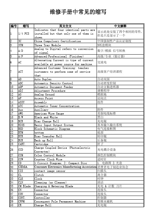
from machine during normal operation 电磁辐射
and
58 EMI
Electro Magnetic Induction
电磁感应
59 EP
Electrophotography
Electro-Photography Cartridge;
60 EP Cartrid sometimes referred to as the Print
高压板
Hertz (Cycles per second)
赫兹
Interface
接口
Input and output
输入输出
Intermediate Belt Transfer
转印带
Integrated Circuit
集成电路
Image Density (or Identification)
图像浓度
Intelligent Drive Electronics or Embedded Drive Electronics
that
Auto Duplex
自动双面
Automatic Density Control
自动密度控制
Automatic Document Feeder
自动文稿进纸器
Adjustment Procedure
调整程序
Analog Ground
模拟地
Access Point
访问点
Assembly
组件
Automatic Toner Concentration
26 CCD
27 CCM 28 CCW 29 CD 30 CEMA 31 CIS 32 CL. 33 CLK 34 CLN 35 CM Blade 36 CN 37 CON 38 CONT. 39 CPPM 40 CR
Protel DXP 2004 基本功能操作
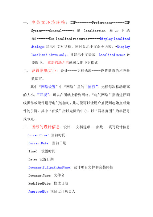
一.中英文环境转换:DXP---------Preferences-------DXP System----General------(在localication板块下选择)-------Use localized resources------Display localized dialogs:显示中文对话框,同时显示中文命令内容;-Display localized hints only:只显示中文提示;Localized menus必须选中。
重新启动之后就可以用中文格式二.设置图纸大小:设计-----文档选项-----设置里面的相应参数即可。
其中“网络设置”中“网络”里的“捕获”:光标每次移动距离的大小;“可视”:可以在图纸上看到网格;“电气网络”指当进行画线操作或元件进行电气连接时,此功能可以让用户捕捉到起始点或元件的引脚。
其中“有效”指以光标为中心,以“网格范围”为半径寻找节点。
三.图纸的设计信息:设计---文档选项---参数---填写设计信息CurrentTime:当前时间CurrentDate:当前日期Time: 设置时间Date:设置日期DocumentfullpathAndName:设计项目文件和完整路径DocumentName:文件名ModifiedDate:修改日期ApprovedBy:项目设计负责人CheckedBy:图纸校对人CompanyName:公司名称DrawnBy:图纸绘制者Engineer:设计工程师Orgnization:设计机构名称Address1 ,Address2,Address3,Address4:设置地址Title:原理图标题SheetNumber:电路原理图编号DocumentNumber:文本编号SheetTotal:整个项目原理图总数Revision:设计图纸版本号 Rule:设计规则ImagePath:影像路径四.原理图各个元件整体注释方法:工具-----注释---左上角处理顺序:Across Then Down—先上后下,先左后右;Up Then Across:先下后上,先左后右;Across Then Up:先左后右,先下后上;Across Then Down:先左后右,先上后下。
Altium Designer Winter 09原理图环境设置

深入了解Altium Designer原理图环境设置原理图环境设置主要指图纸和游标设置。
绘制原理图首先要设置图纸,如设置纸张大小、标题框、设计文件信息等,确定图纸档的有关参数。
图纸上的游标为放置组件、连接线路带来很多方便。
2.3.1 图纸大小的设置1 . 打开图纸设置对话框图 2‐11 图纸属性设置对话框● 在 SCH 电路原理图编辑接口下,执行菜单命令 Design/Options ,将弹出 Document Options (图纸属性设置)对话框,如图 2-11 所示。
● 在当前原理图上单击右键,弹出右键快捷菜单,从弹出的右键菜单中选择 Document Options 选项,同样可以弹出如图 2-11 所示对话框。
2.3.2 格点和游标的设置1 .格点形状和颜色的设置图 2‐13 线状格点图 2‐14 点状格点Altium Designer 6.0 提供了两种格点,即 Lines (线状格点)和 Dots (点状格点),分别如图 2-15 和图 2-16 所示。
设置点状格点和线状格点的具体步骤如下:(1)在 SCH 原理图图纸上右击,在弹出的快捷菜单中选择 Preferences 选项,将弹出如图 2-15 所示的 Preference 对话框。
或者执行菜单命令 Tool/Preferences ,也可以弹出 Preferences 对话框。
单击 Grids 卷标,打开 Grids选项卡。
(2)在 Visible Grid 选项的下拉列表中有两个选项,分别为 Line Grid 和 Dot Grid 。
如选择 Line Grid 选项,则在原理图图纸上显示如图 2-14 所示的线状格点;如选择 Dot Grid 选项,则在原理图图纸上显示如图 2-14 所示的点状格点。
图 2‐17 Parameters 选项卡设置 图 2‐15 Preferences 对话框(3)在 Color Options 选项中, Grid Color 项可以进行格点颜色设置。
DXP菜单命令

附录1 菜单命令F1.1 DXP菜单命令1.Customize…:自定义菜单的内容、快捷键和工具按钮。
2.System Preferences…:设置Protel DXP的原始设置环境、备份路径等。
3.System Info…:EDA Service,Protel DXP可以兼容的文件。
4.Run Process…:运行某一程序。
5.Licensing…:Protel DXP的许可信息。
6.Run Script:选择并打开已有的文件。
7.Run Script Debugger:执行某文件的调试程序。
F1.2 初始菜单命令(未建立任何文件)灰色菜单表明当前菜单不可用。
F1.2.1 File菜单1.New:新建文件,在右边的子菜单中可以选择原理图、PCB等。
2.Open…:打开已经建立的文件。
3.Close:关闭现在打开的文件。
4.Open Project…:打开已存在的项目文件。
5.Open Design Workspace…:打开已存在的设计工作空间。
6.Save Project:保存当前项目文件。
7.Save Project As…:将当前项目文件另存为。
8.Save Design Workspace:保存当前设计工作空间。
9.Save Design Workspace As…:将当前设计工作空间另存为。
10.Save All:保存当前所有打开的文件等。
11.Recent Documents:打开右边子菜单的最近的设计文件。
12.Recent Projects:打开右边子菜单的最近的项目文件。
13.Recent Workspace:打开右边子菜单的最近的工作空间。
14.Exit:退出Protel DXP系统。
F1.2.2 View菜单1.Toolbars:显示的工具箱。
2.Workspace Panels:显示工作空间面板。
1)Design Compiler:显示设计编译器。
2)Help:显示帮助文件。
《Protel DXP 2004 电路板设计实例与操作》教学课件 第5章 原理图绘制提高与后期处理

5.1.1 什么是层次原理图
层次原理图主要用于表达规模较大的复杂电路系统,它把整个电路设 计成一个母原理图和假设干个子原理图。其中,用于表达子原理图之间关 系的原理图称为母原理图,它由图纸符号、图纸入口和连线等组成。每个 图纸符号代表一个子原理图,图纸入口是图纸符号〔即子原理图〕之间连 接的端口。
:::::《Protel DXP 2004电路板设计实例与操作》:::::
5.2.3 生成各种报表
在弹出的“Export For〞对话框中,为元件清单报表选取要保存到的位 置后,在“文件名〞编辑框中输入报表的名称,然后单击“保存〞按钮,即 可生成元件清单报表。
:::::《Protel DXP 2004电路板设计实例与操作》:::::
图纸 符号
图纸 入口
连 线
:::::《Protel DXP 2004电路板设计实例与操作》:::::
5.1.2 层次原理图的设计方法
层次原理图的设计过程就是对母原理图和子原理图分别进行设计 的过程,具体实现方法有两种:一种是自上而下进行设计,即先绘制 母图,再绘制子图;另一种是自下而上进行设计,即先绘制子图,再 绘制母图。
:::::《Protel DXP 2004电路板设计实例与操作》:::::
5.2.4 打印原理图
选择“文件〞>“打印预览〞菜单,可以翻开“Preview Schematic Prints of...〞〔原理图打印预览〕窗口,预览一下打印效果。
:::::《Protel DXP 2004电路板设计实例与操作》:::::
5.2.3 生成各种报表
3.工程组织结构报表
对于包含层次原理图的电路系统,为了能够看清设计文件中各原理图之 间的母子关系以及连接关系,我们通常还要为其生成工程组织结构报表。选 择“报告〞>“Report Project Hierarchy〞〔报告工程层次〕菜单,即可为 当前PCB工程生成工程组织结构报表。
schematic

79
单芯片JTAG配置电路
80
JTAG配置时,专用配置信号接法
存放在已有库中,或另建立新的元件库。
例子
13
新建元件
新建元件的步骤:
命名 类别 确定或调整其大小 添加引脚 添加外框或图形 保存
例子 元件的主要内容是其引脚,体现其电气连接的数量和 属性。
14
引脚的属性
名称
号码
电气特性
形状、位置
15
引脚名称
传统的:
51
驱动能力
一般驱动能力,扇出系数
地址/数据总线,CPU模块等需要增加驱动能力
总线驱动器
3态和双向信号
52
不使用的输入和总线保持
不允许悬空的输入
CMOS输入结构和特性
TTL和关门电阻
总线的保持和上/下拉
53
工作电压和匹配
各种工作电压产生的输入/输出电平不同,可能
23
常规元件和标准库
24
常规元件
来源:
软件自带 常规元件种类:
分立元件(discrete) 中小规模集成电路 接插件(连接器) 电源模块
用于原理图绘制的特殊符号
25
分立元件
电阻: 阻值、功率
精度,E24, E96等
电容: 容量、极性、材质 二/三极管/FET: 种类很多,注意伏安特性 LED: 亮度和电流 按键、拨动开关和跳线 电阻排 LED排
检查 电源
一般原则: 有限地使用软件自带的元件库,尽可能减少 使用的库文件的数量,一组相关设计只使用一个新元 件库
纺织品印花常见术语的英文翻译

纺织品印花常见术语的英文翻译纺织品印花常见术语的英文翻译蒸化(aging)自动筛网印花(automatic screen printing)满地印花(blotch print)烂花印花(burn—out prints)涪烘(curing)直接印花(direct prints)拔染印花(discharge prints)干法印花(dry prints)双面印花(duplex prints)静电荷(electrostatic charge)静电植绒(electrostatic flocking)按特殊要求印花(engineered print)叠印(fall on)平板(flatbed)植绒印花(flock printing)植绒(flocking)半色调或中间色调(halftone)手工筛网印花(hand screen printing)热转移印花(heat--transfer printing)喷射印花(jet printing)机械植绒(mechanical flocking)罩印(over print)印花色浆(print paste)大木印花胶浆(DM print binder)对花(registration)防染印花(resist printing)滚筒印花(roller printing)圆形筛网印花或圆网印花(rotary screen printing)筛网印花(screen printing)打样(strike off)热转移印花(thermal transfer printing)经纱印花(warp prints)湿罩干印花(wet—On—dry)湿罩湿印花(wet—On—wet)湿法印花(wet prints)印花对花准确/对花不准(print register/off register)water based printing 水印heat transfer printing 热转移印花direct printing 直接印花transfer printing 转移印花roller printing 滚筒印花screen printing 筛网印花block printing 横版印花plate screen printing 平网印花rotary screen printing 园网印花。
orcad footprint和allego对应 -回复
orcad footprint和allego对应-回复Orcad Footprint and Allegro Correspondence: A Comprehensive GuideIntroduction:In the world of electronics design, having accurate and reliable component footprints is essential for successful PCB layout. Two popular software tools used by designers are Orcad and Allegro. In this article, we will explore the correspondence between Orcad Footprint and Allegro, discussing the steps to seamlessly transition between the two software platforms.Section 1: Understanding Orcad Footprint1.1 What is Orcad Footprint?Orcad is a powerful suite of software tools for electronic design automation (EDA). Orcad Footprint, a component of the Orcad family, is used for creating, editing, and managing component footprints, which are representations of physical components used in PCB design.1.2 Creating a Footprint in OrcadTo create a footprint in Orcad, follow these steps:- Open the Orcad PCB Editor tool.- Go to the Footprint menu and select "New Footprint."- Specify the name and package type of the component.- Begin adding pads, traces, and other features according to the manufacturer's datasheet.- Save the footprint for future use.1.3 Associating a Footprint with a Symbol in OrcadIn Orcad Capture, the schematic design tool, you can associate a footprint with a symbol to establish a connection between the schematic and PCB. This step ensures that the correct footprint is used during layout.- Open Orcad Capture.- Add a new symbol or select an existing one.- In the Property Editor, select the associated footprint for the symbol.Section 2: Introduction to Allegro2.1 What is Allegro?Allegro is a comprehensive PCB design software suite developed by Cadence Design Systems. It offers advanced tools and features for design, analysis, and manufacturing of printed circuit boards.2.2 Importing Orcad Footprint into AllegroTo import Orcad Footprint into Allegro, follow these steps:- Open Allegro Design Entry HDL.- Go to the Tools menu and select "Import Orcad PCB Editor Footprints."- Browse and select the desired Orcad footprint file.- Allegro will convert the footprint for use in Allegro PCB Designer.2.3 Using the Converted Footprint in AllegroAfter importing the Orcad footprint into Allegro, you can use it in your PCB design.- Open Allegro PCB Designer.- Place the imported Orcad footprint onto the PCB layout canvas. - Connect the footprint with other components and route traces to complete the design.Section 3: Tips for a Seamless Transition3.1 Ensuring CompatibilityBefore importing Orcad footprint into Allegro, it is crucial to ensure compatibility between the two software versions. Verify the compatibility matrix provided by Cadence Design Systems on theirofficial website.3.2 Verifying Imported Footprint AccuracyAfter importing the Orcad footprint into Allegro, thoroughly review the converted footprint for accuracy. Check dimensions, pad sizes, and other critical details against the original Orcad footprint.3.3 Modifying Footprints in AllegroIn some cases, you may need to make modifications to the imported Orcad footprint in Allegro to align with the specific design requirements. Allegro PCB Designer offers powerful editing tools for making these modifications.3.4 Libraries and SynchronizationTo maintain a consistent library across Orcad and Allegro, establish a proper synchronization process. Ensure that any changes made to Orcad footprints are reflected in the Allegro libraries and vice versa.Conclusion:In this article, we explored the correspondence between Orcad Footprint and Allegro, two widely used software tools in theelectronics industry. We discussed the steps involved in creating and associating footprints in Orcad, as well as importing and utilizing Orcad footprints in Allegro. Additionally, we provided tips for ensuring compatibility, verifying accuracy, and maintaining library synchronization during the transition process. By following these guidelines, designers can seamlessly integrate Orcad footprint designs into Allegro PCB layouts and achieve successful electronic designs.。
基于3D_打印的CNT

时上传至电脑,按式(2) 、式(3) 计算 S。
S=
R / R0
P
R = R0 -R
(2)
(3)
式中:R 为相对阻值变化量,R 0 为初始电阻, R
为加载后电阻值,R / R 0 为电阻变化率,P 为
相对压力变化量。
图 3 不同厚度复合薄膜的电加热性能
1. 4 分析与测试
电磁屏蔽效能( E) :采用 N5232A 网络分析
仪测试复合薄膜试样在 X 波段 (8. 2 ~ 12. 4 GHz)
的反射参数、传输参数,并按式(1) 计算 E。
E = E R +E A +E M
(1)
式中:E R 为材料表面的反射损耗,E A 为材料内部
的吸收损耗,E M 为材料内部的多次反射损耗。
膜试样,其中微结构长为 0. 4 mm,高为 0. 2 mm;
13
这说明 CNT 的加入明显提升了 PLA 材料的电磁
屏蔽性能,其原因是 CNT 具有优异的导电性能,
可在 PLA 基体内形成导电网络。
然后裁剪出具有相同尺寸的导电铜箔作为传感器
的电极层,将裁剪好的导电铜箔贴附在薄膜两面,
完成传感器的组装。
第 1 期 魏聪聪等. 基于 3D 打印的 CNT / PLA 复合材料性能研究
首先通过 3D 打印机打印表面分别为金字塔
形微结构( 见图 1a) 、波浪形微结构( 见图 1b) 的
尺寸为 30 mm × 20 mm × 2 mm 的 CNT / PLA 复合薄
电加热性能:将复合薄膜试样两端用铜箔包
装,使用专用夹具连接到 KA3010P 可编程直流电
源上,同时采用 E6390 红外热像仪记录薄膜试样
打印机恢复设置(Printerrestoresettings)

打印机恢复设置(Printer restore settings)1. turn off the power.2. press and hold the STATION2 key on the operation panel, then turn on the power.3. press and hold the STATION2 key on the operation panel until the printer's mechanical action stops.4. insert a paper of at least A4 size (210mm * 297mm) into the middle of the feeder slot. At this point, the printer will automatically align the paper and send it to the correct print position.The two page test configuration table will be printed and the printer can be stopped to stop the test operation.HCC PR2 advanced passbook printer maintenance manualbasic operationL print self check (each printer must be repaired)1. turn off the power2. press and hold the Station2 button on the operating panel, then turn on the power until the printer initialization action is completed3. insert a A4 sized paper into the middle of the feed slot, when the printer automatically aligns the paper and goes to thecorrect print position4. then cycle back and print out a test configuration tableL parameter settings1. turn off the power2. hold the Station1 and Station2 keys on the operating panel at the same time, then turn on the power until the printer initialization action is completed3. insert a A4 specification paper into the paper tray4. the printer starts drawing paper and prints two lines of prompt information5. press the Local button once, and the printer goes into settings6. if you press the Station1 key, you recognize and save the parameter; if you press the Station2 key, change the parameter until the parameter you want to change or set is complete7. parameter change is completed, press the Local key, then press the Station1 button once heard the printer send out two clear call after shutdown. (this parameter change good saved)L monitoring program refreshConnect the printer to the COM1 port of the host;Open the top cover of the printer, hold down the [STATION1] and [LOCAL] keys, start the machine and cover the top cover;Run FLASHPR2 VXXX.PR2 on the host;The printer will be downloaded by 8 modules. After downloading, it will check itself once;You need to restore factory parameters before resetting, and then set upConnection between L printer and host:Host (9 hole) printer (25 pin)2-----------------------------------------------------------23-----------------------------------------------------------35-----------------------------------------------------------7Note: more than 3.10 of the versions need to press the [STATION2] button, after the boot, the action stopped, and then press the [STATION1] button to restore the factory parameters, and then download.L sets the parameters of the photosensitive tubeAll photosensitive parameters have been adjusted when PR2 is out of the factory. In use, due to the use of non-standard paper or to change the photosensitive parameters, the photosensitive parameters must be readjusted.PR2 has four light-sensitive detectors:The paper detector includes 2 sets of light emitting tubes and an accepting tube, located in the forward slot for detecting the presence of a printing medium. The light emitted by a light emitting tube is transmitted through an optical fiber.The advancing paper detector belongs to a group of paper detectors, comprising four sets of light emitting tubes and an accepting tube, and light emitted by the light emitting tube is transmitted through an optical fiber.Adjust the paper before printing the document.A paper edge detector is mounted on the print head to check the borders of the printing paper.The advanced paper detector is not installed.The diagram below is the schematic diagram of the photosensitive component:Printer backendFiber 2000 paper paper edge detector in detector (in print head),optical fiber length 2000 2000 2001 1324 short fiber short fiber paper sheet detector detector 12Printer front-endPhotosensitive parameter setting step:1. turn off the power2. turn on the top cover of the printer3. move the print head to the far left of the printer4. [Local] three [Station2] while holding down the [Station1] key, and then turn on the power, hear the ringing calls after the printer let go, turn off the printer on the cover, the [Ready] lights flashing, [Station1] [Local] three [Station2] lights.5. press [Station1] button two times, at this time, the printer has the action of absorbing paper, [Station2] light, put a A4 of white paper.6. press the [Station2] button once, the printer can suck paper into the exit, then the photosensitive parameter settings successfully, at this time after the printer closed, you can re open.7. if the setting fails, a sustained beep signal is issued and the four lights on the control panel blink in different order to indicate the error of the photosensor.READY STATION1 LOCAL STATION2ONSTATION1 LOCAL STATION2X PHOTO1 (long)X PHOTO2X X PHOTO3X PHOTO4X X PHOTO1 (short)X X PHOTO2X X X photosensitive tubeJudgment and treatment of common faultsL fault phenomenon one:The printer in the initialization process head (carriage) against the wall.Print offset (start from the top left, top) and print from the centerCause and treatment of trouble:The accumulation of dirt to clean or replace the photosensitive tube;To clean the print and small platform (printer), and print a black;The guide bar on the left of the printer is shifted and reinstalled;The parameters of the photosensitive tube need to be reset by the parameter drift of the photosensitive tube;Flat cable damaged, need to be replaced.L malfunction two:Printer initialization cannot be completed;Non absorbent paper;The print head is on the right, not back to the left, and the paper motor does not stop turning;When printing, withdraw the paper after inhalation and do not print.Cause and treatment of trouble:The parameters of the photosensitive tube need to be reset by the parameter drift of the photosensitive tubeLong or short fiber needs to be replaced;The photosensitive device is bad and needs to be replaced;There are small pieces of paper in the paper slot, and they are normal after cleaning.L malfunction three:Paper jamCause and treatment of trouble:The paper is bent or damaged and needs to be replaced;The upper foot of the printer is deformed and needs to be adjusted. (adjust the standard: the back foot is 95 degrees, and the back foot is 90 degrees)The lever inside the printer is damaged and needs to be replaced.L malfunction four:Do not return paper or return paper when it is jammed Cause and treatment of trouble:The paper should be made up when the paper is pressed off; (emergency treatment) the direction of the printer is changedfrom "direction of paper" to "forward"Pressing paper damaged, need to be replaced;The wafer lever is damaged and needs to be replaced.L malfunction five:Character leak point (missing pin) when printingCause and treatment of trouble:The flat cable of the print head is damaged and needs to be replacedThe print head coil needs welding weld;The print head plugged (ink ribbon), caused by the needle, should clean the print head;The print pin is damaged and needs to be replaced3.15A/250V fuse on the main board of the printer needs replacingTH3L10 or 9024 damaged on the printer motherboard, need to be replacedL malfunction six:There is no stitch on the printer after printing.Cause and treatment of trouble:The print head is not up and down and the handle needs to be lowered downward;The print head pulley wear should be adjusted;The 3.15A/250VX3 fuse on the printer's main board needs replacing.L malfunction seven:When the power is on, the printer cannot initialize (ie no action on the machine).Failure cause and treatment: (electrical fault)The 1.6A/250V fuse on the main board of the printer needs to be replaced;The 3718 chip on the printer's motherboard is damaged and needs to be replaced;The L6202 chip on the main board of the printer is damaged and needs to be replaced;The L6506D chip on the main board of the printer is damaged and needs to be replaced.L malfunction eight:Turn on the "ON" light is not lit (no power).Cause and treatment of trouble:The power supply section of the printer, 1.6A/250V fuse, needs to be replaced;The main board of the printer is damaged and needs to be replaced;The transformer winding of the power supply part of the printer needs to be replaced;The 5A/250V of the power supply of the printer needs fusing.L malfunction nine:Print pause.Cause and treatment of trouble:The printer's data line is bad and needs to be replaced;The motherboard is damaged and needs to be replaced;Print head aging, need to be replaced.L malfunction ten:Print the head with your hand. The print head cannot be left.Cause and treatment of trouble:The commutator needs to be reassembled.L malfunction eleven:Punch the paper when you print it.Cause and treatment of trouble:Compress the compression ratio of the report too big, change to small 4/5 or print, press the [STATION2] light to press out, carry on the high-speed printing (OKI simulation);When printing too close to the paper, you need to adjust the pulley on the print head.L malfunction twelve:Print a scratch or print, the paper is blackCause and treatment of trouble:The print head is too dirty to clean the print head.L malfunction thirteen:Print blurCause and treatment of troubleThe print head, the guide pin, falls off and needs to be filled.L malfunction fourteen:When printing, the ribbon does not rotateCause and treatment of troubleThe intermediate gear is damaged and needs to be replaced;The commutator gear is damaged and needs to be replaced;The ribbon drive shaft is damaged and needs to be replacedL malfunction fifteen:Boot strange ringCause and treatment of troubleThe ribbon is stuck on the advancing wheel and needs to be cleaned;The ribbon is stuck on the paper motor and needs to be cleaned.。
电路基础 英文教学 1

4. Power
p = ui
p = − ui
•Emphasis重点 1.current and voltage reference direction
Active elements (有源元件)
dependent source 受控源
Summary: 1. Current 2. Voltage 3. Potential
dq i = L ( A) dt
dw u = L (V ) dq
u a − u b = u ab L (V ) let
a I
u b = 0 L b 点为参考点
from EQ (1-1),the energy absorbing or supplied by an element from time t0 to t is
w =
∫
t
t0
pdt = ∫ vidt
t0
t
Unit is joules(J) 1Wh=3600J
Example:The electron beam in a TV picture tube carries 1015 electrons per second. As a design engineer, determine the voltage U0 needed to accelerate the electron beam to achieve 4W. Solution: dq −19 15 −4 i = = (−1.6×10 )(10 ) =−1.6×10 A dt
(c): P= -UI,
In a source set, the current reference direction is directed out of the + polarity marking (or the first subscript) of the voltage.
Cadence Virtuoso原理图PDF打印

万如意于 XXXXX学习 总结Cadence Virtuoso Schematic 打印设置步骤---------我们的世界太多的纷纷扰扰,忘了哪里才有最真的微笑。
万如意于 XXXXXX学习 总结起因:在原理图需要打印时,这样看图更加直观时,就出现 打印不便 解决方法(三种) 1. 使用截图打印,简单易行。
但是打印精度不高。
2.利用LINUX的系统特点。
一切设备都是文件。
只需建立打 印机设备文件就可。
这个方法俺系统理解不深刻不会搞。
3.使用Cadence自己的打印机文件。
缺点是只能打印黑白。
(貌似)---------我们的世界太多的纷纷扰扰,忘了哪里才有最真的微笑。
万如意于 XXXXXX学习 总结 设置步骤: 添加export PATH=…../tools/plot/bin:$ PATH //添加打印机目录 添加export LD_LIBRARY_PATH=…../tools/plot/bin: $ PATH //具体什么作用我也不知道,我这样搞就可用 终端中使用plotconfig,就会跳出打印机配置窗口,可以鼠标选择 打印机,保存就可。
但是我这样报….figEXE…so.2 出错。
没这样 做 cp …../tools/plot/samples/cdsplotinit.samples ~/. cdsplotinit 使用Virtuoso Schematic 设计 plot submit 命令 点击 设置plot options按钮 ,设置我们需要的ps后缀文件。
两次 OK之后,就产生了例如:myPDFtest_inv.ps文件。
使用ps工具打开,你会很失望,是空白的,很正常。
在终端中输 入:ps2pdfwr myPDFtest_inv.ps myPDFtest_inv.pdf 这样 就生成了PDF文件了,就可后续操作了。
精度很高 ,听说可以彩 色。
---------我们的世界太多的纷纷扰扰,忘了哪里才有最真的微笑。
介绍印刷方式的英语作文

介绍印刷方式的英语作文英文回答:Types of Printing Processes。
Printing is a process of transferring ink to paper or other materials to create an image or text. There are various printing processes, each with its own advantagesand disadvantages. Here are some of the most common typesof printing processes:1. Offset Printing。
Offset printing, also known as lithography, is the most widely used printing process in the commercial industry. It involves transferring the image from a metal plate to a rubber roller and then to the paper. Offset printing allows for high-quality and precise printing with a wide range of colors and finishes. It is suitable for printing large quantities of materials such as magazines, books, brochures,and packaging.2. Flexography。
Flexography is a printing process that uses flexible printing plates made of rubber or photopolymer. It is commonly used for printing packaging materials such as labels, flexible packaging, and corrugated boxes. Flexography is known for its durability, low cost, and adaptability to various substrates. It is also suitable for printing on uneven surfaces.3. Gravure Printing。
Altium_Designer官方标准教程_第2章_设计管理器
第2章 Altium Designer 6.0 设计管理器Altium Designer 6.0 的所有电路设计工作都必须在 Design Explorer (设计管理器)中进行,同时设计管理器也是 Altium Designer 6.0 启动后的主工作接口。
设计管理器具有友好的人机接口,而且设计功能强大,使用方便,易于上手。
因此本章将对设计管理器的使用进行详尽的介绍。
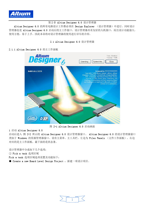
2.1 Altium Designer 6.0 设计管理器2.1.1 Altium Designer 6.0 的主工作面板图 2-1 Altium Designer 6.0 启动画面1 启动 Altium Designer 6.0启动后进入图 2-2 所示的 Altium Designer 6.0 设计管理器窗口。
Altium Designer 6.0 的设计管理器窗口类似于 Windows 的资源管理器窗口。
设有主菜单、主工具栏,左边为 Files Panels (文件工作面板),右边对应的是主工作面板,最下面的是状态条。
设计管理器中分成如下几个选项:① Pick a task 选项区域Pick a task 选项区域选项设置及功能如下:● Create a new Board Level Design Project :新建一项设计项目。
图 2-2 Altium Designer 6.0 设计管理器窗口Altium Designer 6.0 中以设计项目为中心,一个设计项目中可以包含各种设计文件,如原理图 SCH 文件,电路图 PCB 文件及各种报表,多个设计项目可以构成一个 Project Group (设计项目组)。
因此,项目是 Altium Designer 6.0 工作的核心,所有设计工作均是以项目来展开的。
介绍一下使用项目的好处。
图 2-3 新建 FPGA 项目设计档工作● Create a new FPGA Design Project :新建一项 FPGA 项目设计。
