[2016 PAMI]Automatic Shadow Detection and Removal from a Single Image
活力(ACTI)E936 2MP 视频分析型室外мини域眼镜摄像头说明书

CE (EN 55022 Class B, EN 55024), FCC (Part15 Subpart B Class B), IK10, IP68, NEMA 4X, EN50155
Dome Cover
PDCX-1111
2-inch, smoke, vandal proof (IK10)
Popular Mounting Solutsories not required
Power Supply
Wall
PMAX-0316
PPOE-0001
IEEE 802.3af PoE Injector for Class 1, 2 or
3 devices, with universal adapter
Pendant
PMAX-0111
PMAX-1400
+
Gang Box PMAX-0805
NPT
PMAX-0809
Standard PMAX-1400
+
Mounts
Unit: mm [inch]
* Latest product information: /products/ * Accessory information: /mountingselector
• Alarm
Alarm Trigger
Alarm Response
• Interface
Local Storage
• General
Power Source / Consumption Weight Dimensions (Ø x H) Environmental Casing Mount Type Starting Temperature Operating Temperature Operating Humidity Approvals
Infoprint 250 導入と計画の手引き 第 7 章ホスト
SUBNETMASK
255.255.255.128
Type of service...............: TOS
*NORMAL
Maximum transmission unit.....: MTU
*LIND
Autostart.....................:
AUTOSTART
*YES
: xx.xxx.xxx.xxx
: xx.xxx.xxx.xxx
*
(
)
IEEE802.3
60 1500
: xxxx
48 Infoprint 250
31. AS/400
IP
MTU
1
1
IPDS TCP
CRTPSFCFG (V3R2)
WRKAFP2 (V3R1 & V3R6)
RMTLOCNAME RMTSYS
MODEL
0
Advanced function printing............:
AFP
*YES
AFP attachment........................:
AFPATTACH
*APPC
Online at IPL.........................:
ONLINE
FORMFEED
*CONT
Separator drawer......................:
SEPDRAWER
*FILE
Separator program.....................:
SEPPGM
*NONE
Library.............................:
Dynamic Taint Analysis for Automatic Detection, Analysis,and 分析自动检测,动态污点分析,和
Memory is mapped to TDS
Result is mapped to TDS
Dynamic taint analysis
TaintAssert
It checks whether tainted data is used in ways that its policy defines as illegitimate.
Does not require source code or specially compiled binaries. Reliably detects most overwrite attacks. Has no known false positives. Enables automatic semantic analysis based signature generation.
If values are copied from hard-coded literals, rather than arithmetically derived from the input.
IIS translates ASCII input into Unicode via a table
Memory is mapped to TDS
Dynamic taint analysis
TaintTracker
It tracks each instruction that manipulates data in order to determine whether the result is tainted.
E.g. A program uses tainted data as a format string, but makes sure it does not use it in a malicious way.
ShadowDefender(影子卫士)
ShadowDefender(影⼦卫⼠)Shadow Defender软件特⾊ 1、Shadow Defender防⽌所有病毒和恶意软件对电脑的攻击。
2、Shadow Defender安⼼上⽹,消除不必要的痕迹。
3、保护您的隐私。
4、Shadow Defender消除系统停机时间和维护成本。
5、重新启动后电脑系统便可以还原回其原始状态。
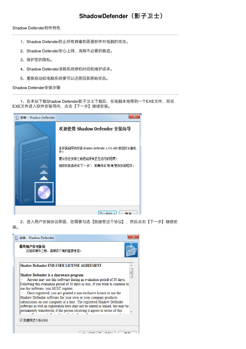
Shadow Defender安装步骤 1、在本站下载Shadow Defender影⼦卫⼠下载后,在电脑本地得到⼀个EXE⽂件,双击EXE⽂件进⼊软件安装导向,点击【下⼀步】继续安装。
2、进⼊⽤户安装协议界⾯,您需要勾选【我接受这个协议】,然后点击【下⼀步】继续安装。
3、需要您输⼊⽤户信息,输⼊完成后点击【下⼀步】继续。
4、选择Shadow Defender (影⼦卫⼠)快捷⽅式的开始⽬录,选择完成后点击【下⼀步】 5、选择附加任务后,您可以⾃⾏勾选【创建桌⾯快捷⽅式】和【创建快速启动栏图标】,选择完成后单击【下⼀步】。
6、准备安装Shadow Defender (影⼦卫⼠),您可以点击【安装】。
7、软件正在安装中,您需要耐⼼等待软件安装完成。
8、Shadow Defender (影⼦卫⼠)安装完成,需要您重启电脑才,您可以⾃⾏选择是否重启电脑,选择完成后,点击【完成】就可以了。
Shadow Defender使⽤⽅法 ⼀、启动影⼦保护 1、双击Shadow Defender (影⼦卫⼠)桌⾯快捷⽅式,进⼊软件界⾯。
2、选择C盘,单击【进⼊影⼦模式】,在弹出窗⼝中选择【重启后继续影⼦模式】。
3、重启后影⼦模式继续,C盘出于影⼦保护之下,不会记录任何更改和设置。
⼆、⽂件排除功能的使⽤ 1、运⾏Shadow Defender软件,如果我们希望桌⾯能够继续保存⽂件,那么久单击【添加⽂件夹】,吧桌⾯⽬录添加到【排除列表】中。
2、这样即使重启电脑,桌⾯上的⽂件仍会完好⽆损。
AXIS P1465-LE 2 MP 全能防盗摄像头说明书
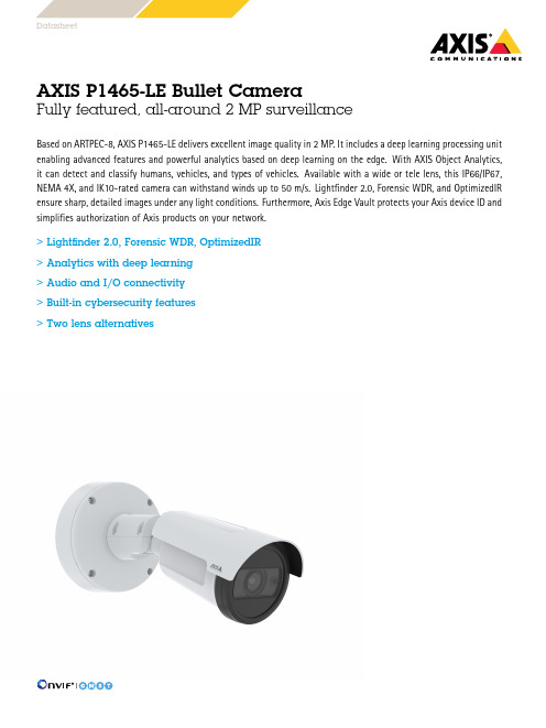
DatasheetAXIS P1465-LE Bullet CameraFully featured,all-around2MP surveillanceBased on ARTPEC-8,AXIS P1465-LE delivers excellent image quality in2MP.It includes a deep learning processing unit enabling advanced features and powerful analytics based on deep learning on the edge.With AXIS Object Analytics, it can detect and classify humans,vehicles,and types of vehicles.Available with a wide or tele lens,this IP66/IP67, NEMA4X,and IK10-rated camera can withstand winds up to50m/s.Lightfinder2.0,Forensic WDR,and OptimizedIR ensure sharp,detailed images under any light conditions.Furthermore,Axis Edge Vault protects your Axis device ID and simplifies authorization of Axis products on your network.>Lightfinder2.0,Forensic WDR,OptimizedIR>Analytics with deep learning>Audio and I/O connectivity>Built-in cybersecurity features>Two lens alternativesAXIS P1465-LE Bullet Camera CameraModels AXIS P1465-LE9mmAXIS P1465-LE29mmImage sensor1/2.8”progressive scan RGB CMOSPixel size2.9µmLens Varifocal,remote focus and zoom,P-Iris control,IR correctedAXIS P1465-LE9mm:Varifocal,3-9mm,F1.6-3.3Horizontal field of view117˚-37˚Vertical field of view59˚-20˚Minimum focus distance:0.5m(1.6ft)AXIS P1465-LE29mm:Varifocal,10.9-29mm,F1.7-1.7Horizontal field of view29˚-11˚Vertical field of view16˚-6˚Minimum focus distance:2.5m(8.2ft)Day and night Automatic IR-cut filterHybrid IR filterMinimum illumination 0lux with IR illumination on AXIS P1465-LE9mm: Color:0.06lux,at50IRE F1.6 B/W:0.01lux,at50IRE F1.6 AXIS P1465-LE29mm: Color:0.06lux,at50IRE F1.7 B/W:0.01lux,at50IRE F1.7Shutter speed With Forensic WDR:1/37000s to2sNo WDR:1/71500s to2sSystem on chip(SoC)Model ARTPEC-8Memory1024MB RAM,8192MB Flash ComputecapabilitiesDeep learning processing unit(DLPU) VideoVideo compression H.264(MPEG-4Part10/AVC)Baseline,Main and High Profiles H.265(MPEG-H Part2/HEVC)Main ProfileMotion JPEGResolution16:9:1920x1080to160x9016:10:1280x800to160x1004:3:1280x960to160x120Frame rate With Forensic WDR:Up to25/30fps(50/60Hz)in all resolutions No WDR:Up to50/60fps(50/60Hz)in all resolutionsVideo streaming Up to20unique and configurable video streams aAxis Zipstream technology in H.264and H.265Controllable frame rate and bandwidthVBR/ABR/MBR H.264/H.265Low latency modeVideo streaming indicatorSignal-to-noiseratio>55dBWDR Forensic WDR:Up to120dB depending on sceneMulti-viewstreamingUp to8individually cropped out view areasNoise reduction Spatial filter(2D noise reduction)Temporal filter(3D noise reduction)Image settings Saturation,contrast,brightness,sharpness,white balance,day/night threshold,exposure mode,exposure zones,defogging,compression,orientation:auto,0°,90°,180°,270°includingcorridor format,mirroring of images,dynamic text and imageoverlay,polygon privacy masks,barrel distortion correctionScene profiles:forensic,vivid,traffic overviewAXIS P1465-LE29mm:Electronic image stabilization Image processing Axis Zipstream,Forensic WDR,Lightfinder2.0,OptimizedIR Pan/Tilt/Zoom Digital PTZ,digital zoomAudioAudio features AGC automatic gain controlNetwork speaker pairing Audio streaming Configurable duplex:One-way(simplex,half duplex)Two-way(half duplex,full duplex)Audio input10-band graphic equalizerInput for external unbalanced microphone,optional5Vmicrophone powerDigital input,optional12V ring powerUnbalanced line inputAudio output Output via network speaker pairingAudio encoding24bit LPCM,AAC-LC8/16/32/44.1/48kHz,G.711PCM8kHz,G.726ADPCM8kHz,Opus8/16/48kHzConfigurable bit rateNetworkNetworkprotocolsIPv4,IPv6USGv6,ICMPv4/ICMPv6,HTTP,HTTPS b,HTTP/2,TLS b,QoS Layer3DiffServ,FTP,SFTP,CIFS/SMB,SMTP,mDNS(Bonjour),UPnP®,SNMP v1/v2c/v3(MIB-II),DNS/DNSv6,DDNS,NTP,NTS,RTSP,RTP,SRTP/RTSPS,TCP,UDP,IGMPv1/v2/v3,RTCP,ICMP,DHCPv4/v6,ARP,SSH,LLDP,CDP,MQTT v3.1.1,Syslog,Link-Localaddress(ZeroConf)System integrationApplicationProgrammingInterfaceOpen API for software integration,including VAPIX®,metadataand AXIS Camera Application Platform(ACAP);specifications at/developer-community.ACAP includes Native SDK andComputer Vision SDK.One-click cloud connectionONVIF®Profile G,ONVIF®Profile M,ONVIF®Profile S andONVIF®Profile T,specification at VideomanagementsystemsCompatible with AXIS Companion,AXIS Camera Station,videomanagement software from Axis’Application DevelopmentPartners available at /vmsOnscreencontrolsAutofocusDay/night shiftDefoggingVideo streaming indicatorWide dynamic rangeIR illuminationPrivacy masksMedia clipAXIS P1465-LE29mm:Electronic image stabilizationEvent conditions ApplicationDevice status:above operating temperature,above or belowoperating temperature,below operating temperature,withinoperating temperature,IP address removed,new IP address,network lost,system ready,ring power overcurrent protection,live stream activeDigital audio input statusEdge storage:recording ongoing,storage disruption,storagehealth issues detectedI/O:digital input,manual trigger,virtual inputMQTT:subscribeScheduled and recurring:scheduleVideo:average bitrate degradation,day-night mode,tampering Event actions Audio clips:play,stopDay-night modeI/O:toggle I/O once,toggle I/O while the rule is activeIllumination:use lights,use lights while the rule is activeMQTT:publishNotification:HTTP,HTTPS,TCP and emailOverlay textRecordings:SD card and network shareSNMP traps:send,send while the rule is activeUpload of images or video clips:FTP,SFTP,HTTP,HTTPS,networkshare and emailWDR modeBuilt-ininstallation aidsPixel counter,remote zoom(3x optical),remote focus,autorotationAnalyticsAXIS ObjectAnalyticsObject classes:humans,vehicles(types:cars,buses,trucks,bikes)Trigger conditions:line crossing,object in area,time in area BETAUp to10scenariosMetadata visualized with trajectories and color-coded boundingboxesPolygon include/exclude areasPerspective configurationONVIF Motion Alarm eventMetadata Object data:Classes:humans,faces,vehicles(types:cars,buses, trucks,bikes),license platesConfidence,positionEvent data:Producer reference,scenarios,trigger conditions Applications IncludedAXIS Object AnalyticsAXIS Live Privacy Shield,AXIS Video Motion Detection,activetampering,shock detectionSupportedAXIS Perimeter Defender,AXIS Speed Monitor cSupport for AXIS Camera Application Platform enablinginstallation of third-party applications,see /acap ApprovalsProduct markings CSA,UL/cUL,BIS,UKCA,CE,KC,EACSupply chain TAA compliantEMC CISPR35,CISPR32Class A,EN55035,EN55032Class A,EN50121-4,EN61000-3-2,EN61000-3-3,EN61000-6-1,EN61000-6-2Australia/New Zealand:RCM AS/NZS CISPR32Class ACanada:ICES-3(A)/NMB-3(A)Japan:VCCI Class AKorea:KS C9835,KS C9832Class AUSA:FCC Part15Subpart B Class ARailway:IEC62236-4Safety CAN/CSA C22.2No.62368-1ed.3,IEC/EN/UL62368-1ed.3,IEC/EN62471risk group exempt,IS13252Environment IEC60068-2-1,IEC60068-2-2,IEC60068-2-6,IEC60068-2-14, IEC60068-2-27,IEC60068-2-78,IEC/EN60529IP66/IP67,IEC/EN62262IK10,NEMA250Type4X,NEMA TS2(2.2.7-2.2.9) Network NIST SP500-267CybersecurityEdge security Software:Signed firmware,brute force delay protection,digest authentication,password protection,AES-XTS-Plain64256bitSD card encryptionHardware:Secure boot,Axis Edge Vault with Axis device ID,signed video,secure keystore(CC EAL4+certified hardwareprotection of cryptographic operations and keys)Network security IEEE802.1X(EAP-TLS)b,IEEE802.1AR,HTTPS/HSTS b,TLSv1.2/v1.3b,Network Time Security(NTS),X.509Certificate PKI,IP address filteringDocumentation AXIS OS Hardening GuideAxis Vulnerability Management PolicyAxis Security Development ModelAXIS OS Software Bill of Material(SBOM)To download documents,go to /support/cybersecu-rity/resourcesTo read more about Axis cybersecurity support,go to/cybersecurityGeneralCasing IP66/IP67-,NEMA4X-,and IK10-rated casingPolycarbonate blend and aluminiumColor:white NCS S1002-BFor repainting instructions,go to the product’s supportpage.For information about the impact on warranty,go to/warranty-implication-when-repainting.Power Power over Ethernet IEEE802.3af/802.3at Type1Class3Typical:7.9W,max12.95W10–28V DC,typical7.2W,max12.95WConnectors Network:Shielded RJ4510BASE-T/100BASE-TX/1000BASE-TAudio:3.5mm mic/line inI/O:Terminal block for1alarm input and1output(12V DCoutput,max.load25mA)Power:DC inputIR illumination OptimizedIR with power-efficient,long-life850nm IR LEDsAXIS P1465-LE9mm:Range of reach40m(131ft)or more depending on the sceneAXIS P1465-LE29mm:Range of reach80m(262ft)or more depending on the scene Storage Support for microSD/microSDHC/microSDXC cardRecording to network-attached storage(NAS)For SD card and NAS recommendations see Operatingconditions-40°C to60°C(-40°F to140°F)Maximum temperature according to NEMA TS2(2.2.7):74°C(165°F)Start-up temperature:-40°CHumidity10–100%RH(condensing)Storageconditions-40°C to65°C(-40°F to149°F)Humidity5-95%RH(non-condensing)DimensionsØ132x132x280mm(Ø5.2x5.2x11.0in)Effective Projected Area(EPA):0.022m2(0.24ft2)Weight With weather shield:1.2kg(2.65lb)Box content Camera,installation guide,TORX®L-keys,terminal blockconnector,connector guard,cable gaskets,AXIS Weather ShieldL,owner authentication keyOptionalaccessoriesAXIS T94F01M J-Box/Gang Box Plate,AXIS T91A47Pole Mount,AXIS T94P01B Corner Bracket,AXIS T94F01P Conduit Back Box,AXIS Weather Shield K,Axis PoE MidspansFor more accessories,go to /products/axis-p1465-le#accessoriesSystem tools AXIS Site Designer,AXIS Device Manager,product selector,accessory selector,lens calculatorAvailable at Languages English,German,French,Spanish,Italian,Russian,SimplifiedChinese,Japanese,Korean,Portuguese,Traditional Chinese Warranty5-year warranty,see /warrantyPart numbers Available at /products/axis-p1465-le#part-numbers SustainabilitySubstancecontrolPVC free,BFR/CFR free in accordance with JEDEC/ECA StandardJS709RoHS in accordance with EU RoHS Directive2011/65/EU/andEN63000:2018REACH in accordance with(EC)No1907/2006.For SCIP UUID,see /partner.Materials Screened for conflict minerals in accordance with OECDguidelinesTo read more about sustainability at Axis,go to/about-axis/sustainabilityEnvironmentalresponsibility/environmental-responsibilityAxis Communications is a signatory of the UN Global Compact,read more at a.We recommend a maximum of3unique video streams per camera or channel,for optimized user experience,network bandwidth,and storage utilization.A unique video stream can be served to many video clients in the network using multicast or unicast transport method via built-in stream reuse functionality.b.This product includes software developed by the OpenSSL Project for use in the OpenSSL Toolkit.(),and cryptographic software written by Eric Young (*****************).c.It also requires AXIS D2110-VE Security Radar with firmware10.12or later.Dimension drawingKey features and technologiesBuilt-in cybersecurityAxis Edge Vault is a secure cryptographic compute module (secure module or secure element)in which the Axis device ID is securely and permanently installed and stored. Secure boot is a boot process that consists of an unbro-ken chain of cryptographically validated software,starting in immutable memory(boot ROM).Being based on signed firmware,secure boot ensures that a device can boot only with authorized firmware.Secure boot guarantees that the Axis device is completely clean from possible malware after resetting to factory default.Signed firmware is implemented by the software vendor signing the firmware image with a private key,which is se-cret.When firmware has this signature attached to it,a device will validate the firmware before accepting and in-stalling it.If the device detects that the firmware integrity is compromised,it will reject the firmware upgrade.Axis signed firmware is based on the industry-accepted RSA pub-lic-key encryption method.ZipstreamThe Axis Zipstream technology preserves all the important forensic in the video stream while lowering bandwidth and storage requirements by an average of50%.Zipstream also includes three intelligent algorithms,which ensure that rel-evant forensic information is identified,recorded,and sent in full resolution and frame rate.Forensic WDRAxis cameras with wide dynamic range(WDR)technology make the difference between seeing important forensic de-tails clearly and seeing nothing but a blur in challenging light conditions.The difference between the darkest and the brightest spots can spell trouble for image usability and clarity.Forensic WDR effectively reduces visible noise and artifacts to deliver video tuned for maximal forensic usabil-ity.LightfinderThe Axis Lightfinder technology delivers high-resolution, full-color video with a minimum of motion blur even in near darkness.Because it strips away noise,Lightfinder makes dark areas in a scene visible and captures details in very low light.Cameras with Lightfinder discern color in low light better than the human eye.In surveillance,color may be the critical factor to identify a person,an object,or a vehicle.AXIS Object AnalyticsAXIS Object Analytics adds value to your camera for free.It detects and classifies humans,vehicles,and types of vehi-cles.Thanks to AI-based algorithms and behavioral con-ditions,it analyzes the scene and their spatial behavior within—all tailored to your specific needs.Scalable and edge-based,it requires minimum effort to set up and sup-ports various scenarios running simultaneously.Two lens alternativesThe camera is available in two variants with a choice of lenses:a wide3.9-9mm lens for wide area surveillance and a tele10-29mm lens for surveillance from a distance.OptimizedIRAxis OptimizedIR provides a unique and powerful combi-nation of camera intelligence and sophisticated LED tech-nology,resulting in our most advanced camera-integrated IR solutions for complete darkness.In our pan-tilt-zoom (PTZ)cameras with OptimizedIR,the IR beam automatically adapts and becomes wider or narrower as the camera zooms in and out to make sure that the entire field of view is al-ways evenly illuminated.For more information,see /glossary©2022-2023Axis Communications AB.AXIS COMMUNICATIONS,AXIS,ARTPEC and VAPIX are registered trademarks ofAxis AB in various jurisdictions.All other trademarks are the property of their respective owners.We reserve the right tointroduce modifications without notice.T10181832/EN/M13.2/2302。
消除影子算法

消除影子是计算机视觉中的一个重要任务,它涉及到如何去除图像中的阴影,以便更好地理解和分析图像。
以下是一些消除影子的算法:
1. 基于光照模型的消除影子算法:这种算法假设物体表面受到均匀的光照,因此可以通过计算光照模型来消除阴影。
常用的光照模型包括Lambertian反射模型和Phong光照模型。
这种算法的优点是简单易用,但是它不适用于所有情况,因为实际场景中的光照条件往往不是均匀的。
2. 基于图像处理的消除影子算法:这种算法通常使用图像处理技术来消除阴影,例如使用中值滤波器、高斯滤波器或边缘检测算法等。
这种算法的优点是简单快速,但是它可能会导致图像失真或模糊。
3. 基于深度学习的消除影子算法:这种算法使用深度学习技术来学习阴影的特征,并自动识别和消除阴影。
常用的深度学习模型包括卷积神经网络(CNN)和生成对抗网络(GAN)等。
这种算法的优点是能够自动适应各种情况,但是它需要大量的训练数据和计算资源。
以上是三种常见的消除影子算法,每种算法都有其优缺点,需要根据具体的应用场景选择合适的算法。
vectra polaris 参数

vectra polaris 参数
Vectra Polaris是一款基于人工智能的网络安全分析平台,其参数主要包括以下几个方面:
1. 检测能力:Vectra Polaris可以检测各种网络攻击,包括零日漏洞、隐蔽后门、勒索软件等。
2. 数据分析:Vectra Polaris采用先进的人工智能算法,对网络流量和安全数据进行实时分析,并提供可视化的数据图表和报告。
3. 自动化防护:Vectra Polaris具备自动化的威胁检测和防御功能,可以快速响应各种攻击,并采取相应的防护措施。
4. 安全性:Vectra Polaris采用了多种安全机制,确保数据的安全性和隐私保护。
5. 可扩展性:Vectra Polaris支持横向和纵向扩展,可以根据企业的需求进行灵活配置。
具体来说,Vectra Polaris的参数包括:支持100多种协议和应用的检测、支持多达100万个网络流量的实时分析、可检测和防御超过1000种已知的网络威胁、支持多种数据源的集成和关联分析、支持多种安全标准和合规性要求、支持高可用性和灾难恢复等。
总之,Vectra Polaris是一款功能强大的网络安全分析平台,可以为企业提供全面的网络安全保障。
电脑保护神影子系统PowerShadow学习使用

的电脑,影子系统将是您系统安全的放心选择。
这样可以让用户在不改变电脑使用习惯的前提下,切换到一个更安全的虚拟平台上工作。
有用的文件储存至闪存或者移动磁盘内。
统,你想要修改系统设置、安装新软件,就到正常模式下去做就可以了。
护之中。
计算机也将重启,然后自动进入正常模式。
子系统图标并选择"退出影子模式"后,计算机会自动重启。
(只有在正常模式下才能进行设置)。
打开影子系统软件界面,有选择的来取消或者开启这些提示。
目录迁移
移的目录,点击选择迁移分区,而后点击确定即可。
海康威视网络录像机快速入门指南说明书

Network Video RecorderQuick Start GuideTABLE OF CONTENTSChapter1 Panels Description (8)1.1 Front Panel (8)1.2 Rear Panel (9)NVR-100H-D and NVR-100MH-D Series (9)NVR-100H-D/P and NVR-100MH-D/P Series (10)Chapter 2 Installation and Connections (11)2.1 NVR Installation (11)2.2 Hard Disk Installation (11)2.3 HDD Storage Calculation Chart (13)Chapter 3 Menu Operation (14)3.1 Startup and Shutdown (14)3.2 Activate Your Device (14)3.3 Set the Unlock Pattern for Login (15)3.4 User Login (16)3.5 Network Settings (16)3.6 Add IP Cameras (17)3.7 Live View (18)3.8 Recording Settings (18)3.9 Playback (19)Chapter 4 Accessing by Web Browser (21)Quick Start GuideCOPYRIGHT ©2019 Hangzhou Hikvision Digital Technology Co., Ltd.ALL RIGHTS RESERVED.Any and all information, including, among others, wordings, pictures, graphs are the properties of Hangzhou Hikvision Digital Technology Co., Ltd. or its subsidiaries (hereinafter referred to be “Hikvision”). This user manual (hereinafter referred to be “the Manual”) cannot be reproduced, changed, translated, or distributed, partially or wholly, by any means, without the prior written permission of Hikvision. Unless otherwise stipulated, Hikvision does not make any warranties, guarantees or representations, express or implied, regarding to the Manual.About this ManualThis Manual is applicable to Network Video Recorder (NVR).The Manual includes instructions for using and managing the product. Pictures, charts, images and all other information hereinafter are for description and explanation only. The information contained in the Manual is subject to change, without notice, due to firmware updates or other reasons. Please find the latest version in the company website (/en/).Please use this user manual under the guidance of professionals.Trademarks Acknowledgementand other Hikvision’s trademarks and logos are the properties of Hikvision in various jurisdictions. Other trademarks and logos mentioned below are the properties of their respective owners.The terms HDMI and HDMI High-Definition Multimedia Interface, and the HDMI Logoare trademarks or registered trademarks of HDMI Licensing Administrator, Inc. in the United States and other countries.Legal DisclaimerTO THE MAXIMUM EXTENT PERMITTED BY APPLICABLE LAW, THE PRODUCT DESCRIBED, WITH ITS HARDWARE, SOFTWARE AND FIRMWARE, IS PROVIDED “AS IS”, WITH ALL FAULTS AND ERRORS, AND HIKVISION MAKES NO WARRANTIES, EXPRESS OR IMPLIED, INCLUDING WITHOUT LIMITATION, MERCHANTABILITY, SATISFACTORY QUALITY, FITNESS FOR A PARTICULAR PURPOSE, AND NON-INFRINGEMENT OF THIRD PARTY. IN NO EVENT WILL HIKVISION, ITS DIRECTORS, OFFICERS, EMPLOYEES, OR AGENTS BE LIABLE TO YOU FOR ANY SPECIAL, CONSEQUENTIAL, INCIDENTAL, OR INDIRECT DAMAGES, INCLUDING, AMONG OTHERS, DAMAGES FOR LOSS OF BUSINESS PROFITS, BUSINESS INTERRUPTION, OR LOSS OF DATA OR DOCUMENTATION, IN CONNECTION WITH THE USE OF THIS PRODUCT, EVEN IF HIKVISION HAS BEEN ADVISED OF THE POSSIBILITY OF SUCH DAMAGES.REGARDING TO THE PRODUCT WITH INTERNET ACCESS, THE USE OF PRODUCT SHALL BE WHOLLY AT YOUR OWN RISKS. HIKVISION SHALL NOT TAKE ANY RESPONSIBILITES FOR ABNORMAL OPERATION, PRIVACY LEAKAGE OR OTHER DAMAGES RESULTING FROM CYBER ATTACK, HACKER ATTACK, VIRUS INSPECTION, OR OTHER INTERNET SECURITY RISKS; HOWEVER, HIKVISION WILL PROVIDE TIMELY TECHNICAL SUPPORT IF REQUIRED.SURVEILLANCE LAWS VARY BY JURISDICTION. PLEASE CHECK ALL RELEVANT LAWS IN YOUR JURISDICTION BEFORE USING THIS PRODUCT IN ORDER TO ENSURE THAT YOUR USE CONFORMSTHE APPLICABLE LAW. HIKVISION SHALL NOT BE LIABLE IN THE EVENT THAT THIS PRODUCT IS USED WITH ILLEGITIMATE PURPOSES.IN THE EVENT OF ANY CONFLICTS BETWEEN THIS MANUAL AND THE APPLICABLE LAW, THE LATER PREVAILS.Regulatory InformationFCC InformationPlease take attention that changes or modification not expressly approved by the party responsible for compliance could void the user’s authority to operate the equipment.FCC compliance: This equipment has been tested and found to comply with the limits for a Class A digital device, pursuant to part 15 of the FCC Rules. These limits are designed to provide reasonable protection against harmful interference when the equipment is operated in a commercial environment. This equipment generates, uses, and can radiate radio frequency energy and, if not installed and used in accordance with the instruction manual, may cause harmful interference to radio communications. Operation of this equipment in a residential area is likely to cause harmful interference in which case the user will be required to correct the interference at his own expense.FCC ConditionsThis device complies with part 15 of the FCC Rules. Operation is subject to the following two conditions:1. This device may not cause harmful interference.2. This device must accept any interference received, including interference that may cause undesired operation.EU Conformity StatementThis product and - if applicable - the supplied accessories too are marked with "CE" and comply therefore with the applicable harmonized European standards listed under the EMC Directive 2014/30/EU, the LVD Directive 2014/35/EU, the RoHS Directive 2011/65/EU.2012/19/EU (WEEE directive): Products marked with this symbol cannot be disposed of as unsorted municipal waste in the European Union. For proper recycling, return this product to your local supplier upon the purchase of equivalent new equipment, or dispose of it at designated collection points. For more information see: 2006/66/EC (battery directive): This product contains a battery that cannot be disposed of as unsorted municipal waste in the European Union. See the product documentation for specific battery information. The battery is marked with this symbol, which may include lettering to indicate cadmium (Cd), lead (Pb), or mercury (Hg). For proper recycling, return the battery to your supplier or to a designated collection point. For more information see: Industry Canada ICES-003 ComplianceThis device meets the CAN ICES-3 (A)/NMB-3(A) standards requirements.Applicable ModelsThis manual is applicable to the models listed in the following table.Series ModelNVR-100H-D NVR-104H-D NVR-108H-DNVR-100H-D/P NVR-104H-D/4P NVR-108H-D/8PNVR-100MH-D NVR-104MH-D NVR-108MH-DNVR-100MH-D/P NVR-104MH-D/4P NVR-108MH-D/8PSymbol ConventionsThe symbols that may be found in this document are defined as follows.Symbol DescriptionProvides additional information to emphasize or supplementimportant points of the main text.Indicates a potentially hazardous situation, which if not avoided,could result in equipment damage, data loss, performancedegradation, or unexpected results.Indicates a hazard with a high level of risk, which if not avoided, willresult in death or serious injury.Safety Instructions●Proper configuration of all passwords and other security settings is the responsibility of theinstaller and/or end-user.●In the use of the product, you must be in strict compliance with the electrical safetyregulations of the nation and region. Please refer to technical specifications for detailedinformation.●Input voltage should meet both the SELV (Safety Extra Low Voltage) and the Limited PowerSource with 100~240 VAC, 48 VDC or 12 VDC according to the IEC60950-1 standard. Please refer to technical specifications for detailed information.●Do not connect several devices to one power adapter as adapter overload may causeover-heating or a fire hazard.●Please make sure that the plug is firmly connected to the power socket.●If smoke, odor or noise rise from the device, turn off the power at once and unplug the powercable, and then please contact the service center.●If the POE ports of device do not comply with Limited Power Source, the additional equipmentconnected to POE ports shall have fire enclosure.●The USB interface of the /P devices can be connected with the mouse and U-flash disk storagedevice only.Preventive and Cautionary TipsBefore connecting and operating your device, please be advised of the following tips:●Ensure unit is installed in a well-ventilated, dust-free environment.●Unit is designed for indoor use only.●Keep all liquids away from the device.●Ensure environmental conditions meet factory specifications.●Ensure unit is properly secured to a rack or shelf. Major shocks or jolts to the unit as a result ofdropping it may cause damage to the sensitive electronics within the unit.●Use the device in conjunction with an UPS if possible.●Power down the unit before connecting and disconnecting accessories and peripherals.● A factory recommended HDD should be used for this device.●Improper use or replacement of the battery may result in hazard of explosion. Replace withthe same or equivalent type only. Dispose of used batteries according to the instructionsprovided by the battery manufacturer.Power Supply InstructionsUse only power supplies listed in the user instructions.NVR Models Standard Power Supply Models ManufacturerNVR-104H-D NVR-108H-D NVR-104MH-D NVR-108MH-D EuropeanMSA-C1500IC12.0-18P-DE MOSO Power Supply Technology Co., LtdADS-26FSG-12 12018EPG Shenzhen HONOR Electronic Co., LtdKL-AD3060VA Xiamen Keli Electronics Co., LtdKPD-018-VI Channel Well Technology Co., Ltd BritishADS-25FSG-12 12018GPB Shenzhen HONOR Electronic Co., LtdMSA-C1500IC12.0-18P-GB MOSO Power Supply Technology Co., LtdADS-26FSG-12 12018EPB Shenzhen HONOR Electronic Co., LtdNVR-104H-D/4PNVR-108H-D/8P NVR-104MH-D/4P NVR-108MH-D/8P UniversalMSP-Z1360IC48.0-65W MOSO Power Supply Technology Co., LtdMSA-Z1040IS48.0-65W-Q MOSO Power Supply Technology Co., LtdMSA-Z1360IS48.0-65W-QMOSO Power Supply Technology Co., Ltd●The power supplies list above is for EU countries only.●The power supplies list is subject to change without prior notice.Chapter1 Panels Description 1.1 Front PanelFigure 1-1NVR-100H-D (/P) SeriesFigure 1-2NVR-100MH-D (/P) SeriesTable 1-1Description of Front Panel No. Icon Description1 Indicator turns red when NVR is powered up.2 Indicator lights in red when data is being read from or written to HDD.3 Indicator blinks blue when network connection is functioning properly.1.2 Rear PanelNVR-100H-D and NVR-100MH-D SeriesFigure 1-3NVR-100H-D Rear PanelFigure 1-4NVR-100MH-D Rear PanelNo. Item Description1 Power Supply 12 VDC power supply.2 VGA Interface DB9 connector for VGA output. Display local videooutput and menu.3 HDMI Interface HDMI video output connector.4 USB Interface Universal Serial Bus (USB) ports for additional devicessuch as USB mouse and USB Hard Disk Drive (HDD).5 LAN Network Interface 10/100 Mbps self-adaptive Ethernet interface.6 Ground Ground (needs to be connected when NVR starts up).NVR-100H-D/P and NVR-100MH-D/P SeriesFigure 1-5NVR-100H-D/P Rear PanelFigure 1-6NVR-100MH-D/P Rear PanelTable 1-3Description of Rear Panel No. Item Description1 Power Supply 12 VDC power supply.2 VGA Interface DB9 connector for VGA output. Display local videooutput and menu.3 HDMI Interface HDMI video output connector.4 USB Interface Universal Serial Bus (USB) ports for additional devicessuch as USB mouse and USB Hard Disk Drive (HDD).5 LAN Network Interface 10/100 Mbps self-adaptive Ethernet interface.6 Ground Ground (needs to be connected when NVR starts up).7 Network Interfaces withPoE functionNetwork interfaces for the cameras and to providepower over Ethernet.4 interfaces for /4P models and 8 interfaces for /8Pmodels.Chapter 2 Installation and Connections2.1 NVR InstallationDuring installation of the NVR:●Use brackets for rack mounting.●Ensure ample room for audio and video cables.●When routing cables, ensure that the bend radius of the cables are no less than five times thanits diameter.●Connect the alarm cable.●Allow at least 2cm (≈0.75-inch) of space between racks mounted devices.●Ensure the NVR is grounded.●Environmental temperature should be within the range of -10 to +55º C, +14 to +131º F.●Environmental humidity should be within the range of 10% to 90%.2.2 Hard Disk InstallationBefore you start:Disconnect the power from the NVR before installing a hard disk drive (HDD). A factory recommended HDD should be used for this installation.Tools Required: Screwdriver.Step 1Remove the cover from the device by unfastening the screws on the bottom.Figure 2-1Remove the CoverStep 2Place the HDD on the bottom of the device and then fasten the screws on the bottom to fix the HDD.Figure 2-2Fix the HDDStep 3Connect one end of the data cable to the motherboard of NVR and the other end to the HDD.Step 4Connect the power cable to the HDD.Figure 2-3Connect CablesStep 5Re-install the cover of the NVR and fasten screws.2.3 HDD Storage Calculation ChartThe following chart shows an estimation of storage space used based on recording at one channel for an hour at a fixed bit rate.Bit Rate Storage Used96K42M128K56M160K70M192K84M224K98M256K112M320K140M384K168M448K196M512K225M640K281M768K337M896K393M1024K450M1280K562M1536K675M1792K787M2048K900M4096K 1.8G8192K 3.6G16384K 7.2GPlease note that supplied values for storage space used is just for reference. The storage values in the chart are estimated by formulas and may have some deviation from actual value.Chapter 3 Menu Operation3.1 Startup and ShutdownProper startup and shutdown procedures are crucial to expanding the life of the NVR.To start your NVR:Step 1Check the power supply is plugged into an electrical outlet. It is HIGHLY recommended that an Uninterruptible Power Supply (UPS) be used in conjunction with the device. The Powerbutton) on the front panel should be red, indicating the device is receiving the power.Step 2Press the power switch on the panel. The Power LED should turn blue. The unit will begin to start.After the device starts up, the wizard will guide you through the initial settings, including modifying password, date and time settings, network settings, HDD initializing, and recording.To shut down the NVR:Step 1Go to Menu > Shutdown.Figure 3-1ShutdownStep 2Select Shutdown.Step 3Click Yes.3.2 Activate Your DevicePurpose:For the first-time access, you need to activate the device by setting an admin password. No operation is allowed before activation. You can also activate the device via Web Browser, SADP or client software.Step 1Input the same password in Create New Password and Confirm New Password.Step 2(Optional) Use customized password to activate and add network camera(s) connected to the device.1)Uncheck Use Channel Default Password.2)Enter a password in IP Camera Activation.Figure 3-2Set Admin PasswordSTRONG PASSWORD RECOMMENDED–We highly recommend you create a strong password of your own choosing (Using a minimum of 8 characters, including at least three of the following categories: upper case letters, lower case letters, numbers, and special characters.) in order to increase the security of your product. And we recommend you reset your password regularly, especially in the high security system, resetting the password monthly or weekly can better protect your product.Step 3Click OK.3.3 Set the Unlock Pattern for LoginAdmin can use the unlock pattern for device login.For devices with PoE function, you can draw the device unlock pattern after activation. For other devices, the unlock pattern interface will show after the first-time login.Step 1Use the mouse to draw a pattern among the 9 dots on the screen. Release the mouse when the pattern is done.Figure 3-3Draw the Pattern●Connect at least 4 dots to draw the pattern.●Each dot can be connected for once only.Step 2Draw the same pattern again to confirm it. When the two patterns match, the pattern is configured successfully.3.4 User LoginPurpose:If NVR has logged out, you must login the device before operating the menu and other functions. Step 1Select the User Name in the dropdown list.Figure 3-4LoginStep 2Input Password.Step 3Click OK.In the Login dialog box, if you enter the wrong password 7 times, the current user account will be locked for 60 seconds.3.5 Network SettingsPurpose:Network settings must be properly configured before you operate NVR over network.Step 1Enter the general network settings interface.Menu > Configuration > Network > GeneralFigure 3-5Network SettingsStep 2Configure the following settings: NIC Type, IPv4 Address, IPv4 Gateway, MTU and DNS Server.Step 3If the DHCP server is available, you can check the checkbox of DHCP to automatically obtain an IP address and other network settings from that server.Step 4Click Apply.3.6 Add IP CamerasPurpose:Before you can get live video or record the video files, you should add the network cameras to the connection list of the device.Before you start:Ensure the network connection is valid and correct, and the IP camera to add has already been activated. Please refer to the User Manual for activating the inactive IP camera.You can select one of the following three options to add the IP camera.OPTION 1:Step 1Click to select an idle window in the live view mode.Step 2Click in the center of the window to pop up the Add IP Camera interface.Figure 3-6Add IP CameraStep 3Select the detected IP camera and click Add to add it directly, and you can click Search to refresh the online IP camera manually.Or you can choose to custom add the IP camera by editing the parameters in thecorresponding text field and then click Add to add it.3.7 Live ViewIcons are provided on screen in Live View mode to indicate camera status. These icons include: Live View IconsIn the live view mode, there are icons at the upper-right corner of the screen for each channel, showing the status of the record and alarm in the channel for quick reference.Alarm (video loss, tampering, motion detection, VCA or sensor alarm)Record (manual record, continuous record, motion detection, VCA or alarm triggered record)Alarm and RecordEvent/Exception (event and exception information, appears at the lower-left corner of the screen.)3.8 Recording SettingsBefore you start:Make sure that the disk has already been installed. If not, please install a disk and initialize it. You may refer to the user manual for detailed information.Purpose:Two kinds of record types are introduced in the following section, including Instant Record andAll-day Record. And for other record types, you may refer to the user manual for detailed information.After rebooting all the manual records enabled are canceled.Step 1On the live view window, right lick the window and move the cursor to the Start Recording option, and select Continuous Record or Motion Detection Record on your demand.Figure 3-7Start Recording from Right-click MenuStep 2Click Yes in the pop-up Attention message box to confirm the settings. All the channels will start to record in the selected mode.3.9 PlaybackThe recorded video files on the hard disk can be played back in the following modes: instant playback, all-day playback for the specified channel, and playback bynormal/event/smart/tag/sub-periods/external file search.Step 1Enter playback interface.Click Menu > Playback or from the right-click menuStep 2Check the checkbox of channel(s) in the channel list and then double-click to select a date on the calendar.Step 3You can use the toolbar in the bottom part of Playback interface to control playing progress.Figure 3-8 Playback InterfaceStep 4 Select the channel(s) to or execute simultaneous playback of multiple channels.Chapter 4 Accessing by Web BrowserYou shall acknowledge that the use of the product with Internet access might be under network security risks. For avoidance of any network attacks and information leakage, please strengthen your own protection. If the product does not work properly, please contact with your dealer or the nearest service center.Purpose:You can get access to the device via web browser. You may use one of the following listed web browsers: Internet Explorer 6.0, Internet Explorer 7.0, Internet Explorer 8.0, Internet Explorer 9.0, Internet Explorer 10.0, Internet Explorer 11.0, Apple Safari, Mozilla Firefox, and Google Chrome. The supported resolutions include 1024*768 and above.Step 1Open web browser, input the IP address of the device and then press Enter.Step 2Login to the device.If the device has not been activated, you need to activate the device first before login.Figure 4-1Set Admin Password1)Set the password for the admin user account.2)Click OK.STRONG PASSWORD RECOMMENDED–We highly recommend you create a strong password of your own choosing (using a minimum of 8 characters, including upper case letters, lower case letters, numbers, and special characters) in order to increase the security of your product. And we recommend you reset your password regularly, especially in the high security system, resetting the password monthly or weekly can better protect your product.If the device is already activated, enter the user name and password in the login interface, and click Login.Figure 4-2LoginStep 3Install the plug-in before viewing the live video and managing the camera. Please follow the installation prompts to install the plug-in.You may have to close the web browser to finish the installation of the plug-in.After login, you can perform the operation and configuration of the device, including the live view, playback, log search, configuration, etc.03041041090702。
高清网络摄像机用户手册(IPC410412)
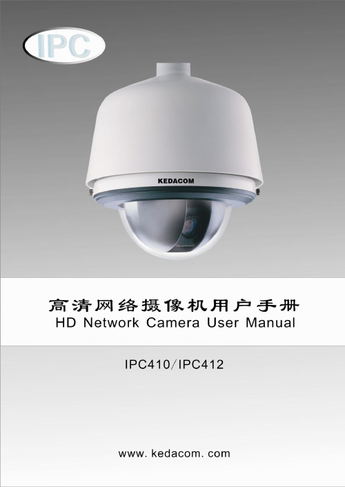
目录/ Contents目录/ CONTENTS (1)前言 (3)读者对象 (3)说明 (3)安全说明 (4)产品简介 (5)安装设备 (6)安装环境 (6)准备线缆 (6)设备安装与连线 (7)开始使用 (15)客户端PC机配置要求 (15)初始配置 (15)使用客户端IPCCtrl (17)产品功能 (18)视频浏览 (18)云台控制 (18)图像调节 (18)告警联动 (20)图像遮蔽 (21)抓拍管理 (22)录像管理 (22)升级管理 (23)附录 (24)FAQ (24)性能指标 (31)术语表 (32)P REFACE (1)T ARGET R EADERS (1)M ODELS (1)R ELATED M ANUALS (1)C AUTION (2)Main features (3)Installation (4)General Environment (4)Connection Cable (4)Mount the device (5)U SING IPC410 (13)System Requirement (13)Initially Configuration (13)Using the Client - IPCCtrl (15)P RODUCT F EATURE (16)Live Video (16)PTZ Control (16)Adjusting the camera and image (16)Alarm Trigger (20)Image Shield (21)S NAPSHOT M ANAGEMENT (21)R ECORD M ANAGEMENT (22)U PDATE (23)A PPENDIX (24)Troubleshooting (24)Specifications (29)G LOSSARY (30)前言前言读者对象工程安装人员监控产品操作人员说明适用型号:IPC410/ IPC412 高清高速球型摄像机相关手册:《NVR管理员指南》本手册详细介绍了IPC410/412的功能、安装和使用操作等方法。
影子系统Shadow Defender图文使用教程
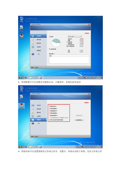
3、管理配置中可以设置是否随机启动,右键菜单、系统托盘等选项
4、排除列表可以设置排除的文件或文件夹,设置后,即使启动影子系统,这些文件或文件
夹有所变化也不会还原(注:下图中添加的文件夹是例子,如果不懂,不要随便设置)
5、影子系统Shadow Defender使用非常简单,点击模式设置,选上想要还原的分区,然后点击进入影子模式
6、设置进入后的设置,如果想要以后也使用,选择重启后继续进入,如果选择第二项的关机后退出影子系统,那么每次关机后再次开机,系统会自动还原到进入影子系统时的状态
7、稍等一会,会提示成功进入影子模式
8、安装一个快播,然后看片。
快播看片方法可以看这里:
9、点击退出影子模式后,会弹出菜单,可以进行设置,退出影子模式必须重启一次系统
10、
重启后系统被还原了,之前安装的快播不见了,用快播看片的事儿也没人知道了。
热值仪中文说明

List of Illustrations------------------------------------------------------------- v
Chapter 1-------------------------------------------------------------------------- 1
符号
文件符号定义
标签
说明
WARNING
包括条件、惯例和步骤必须谨慎执行, 以防人员伤害和设备损坏。
CAUTION
包括条件、惯例和步骤必须谨慎执行, 以防人员伤害和设备损坏
CAUTION
电击或高温部分危险,如不采取适当的 警告,可导致人员伤害。
CAUTION
静电感应元件,要求正确地触摸,以防 损坏。
Flo-Cal 用户手册
ii 索引
Chapter 4 --------------------------------------------------------------------------17
Installation ....................................................................................................... 17 System Mounting .............................................................................................. 17 Unpacking and Inspection .................................................................... 17 Wall Mount Preparation and Procedure ............................................... 18 Free Standing Mount Instructions ........................................................ 20 Electrical Installation......................................................................................... 21 Gas & Air Supply Installation ........................................................................... 22
Bosch IP Cameras FW5.51 软件手册 摄像机浏览器界面说明书

14 14.1 14.1.1 14.2 14.2.1 14.2.2 14.2.3
接口 报警输入 名称 继电器 空闲状态 操作模式 继电器跟随
AM18-Q0613 | v5.51 | 2012.04
软件手册
摄像机浏览器界面
71 72 72 72 72 72 72 72 72 72 73 73 74
75 75 76 76 76 77 78 81 81 81 82 82 82 82 82
摄像机浏览器界面
Bosch IP Cameras FW5.51
zh 软件手册
摄像机浏览器界面
目录
1 1.1 1.2 1.2.1 1.3
浏览器连接 系统要求 建立连接 摄像机中的密码保护 受保护的网络
系统概述
2.1
实况页面
2.2
录像
2.3
设置
3 3.1 3.1.1 3.1.2 3.1.3 3.1.4 3.1.5 3.1.6 3.1.7 3.1.8 3.1.9 3.1.10 3.1.11 3.2 3.2.1
Bosch Security Systems
软件手册
目录 | zh 7
58 58 59 59 60 61 61 61 63 64 64 64 64 65 65 66
67 67 67 67 67 67 68 68 68 68 68 68 68 69 70 71 71 71 71 71
AM18-Q0613 | v5.51 | 2012.04
要回放实况视频图像,必须在计算机上安装适当的 ActiveX。如有必 要,安装 Bosch Video Client。
8 zh | 目录
12.3.5 12.4 12.4.1 12.4.2 12.4.3 12.4.4 12.4.5 12.4.6 12.4.7 12.4.8 12.4.9 12.4.10 12.5
解决增强现实应用中的光照和阴影问题的技巧

解决增强现实应用中的光照和阴影问题的技巧增强现实(Augmented Reality,简称AR)是一种将虚拟场景与真实世界进行叠加的技术,它通过计算机图形、传感器和显示设备等技术手段,将数字信息叠加到真实环境中,实现虚拟与现实的交互。
然而,在增强现实应用中,光照和阴影的问题一直是困扰开发者和使用者的难题。
在本文中,我将介绍一些解决增强现实应用中光照和阴影问题的技巧。
首先,了解光源的位置和方向是解决光照和阴影问题的重要一步。
在增强现实应用中,虚拟物体需要与真实环境进行交互,这意味着虚拟物体的阴影需要与真实物体的阴影一致。
为了实现这一点,开发者应该清楚地了解真实世界中的光源位置和方向,并将这些信息应用到虚拟环境中。
其次,使用真实光线信息来渲染虚拟物体。
通过使用设备中的传感器,如加速度计、陀螺仪和磁力计等,可以获取到真实环境中的光线信息。
开发者可以利用这些信息来模拟真实环境中的光照情况,使虚拟物体看起来更加真实。
另外,使用纹理映射和阴影投射等技术可以增强增强现实应用的真实感。
纹理映射是一种将二维图像映射到三维物体表面的技术,通过给虚拟物体添加真实物体的纹理,可以使虚拟物体与真实环境更加融合。
阴影投射是一种模拟光线在真实世界中产生的阴影效果的技术,通过计算虚拟物体在真实世界中的阴影位置和形状,可以使虚拟物体的阴影更加真实。
此外,使用透明度和反射等技术可以改善增强现实应用中的光照和阴影效果。
透明度是指对于不同材质的虚拟物体,光线在经过物体时的透明程度。
通过设置不同材质的透明度,可以使虚拟物体看起来更加真实。
反射是指在虚拟物体表面反射的光线,通过模拟虚拟物体表面的反射,可以使虚拟物体的阴影效果更加逼真。
最后,根据使用场景调整光照和阴影效果也是解决增强现实应用中光照和阴影问题的关键。
不同的使用场景对光照和阴影的要求不同,例如在户外环境中,光照强烈且方向多变,而在室内环境中,光照相对较弱且稳定。
因此,开发者应根据使用场景的特点,调整光照和阴影效果,以使增强现实应用在不同环境下都能获得良好的展示效果。
计算机图形学中的光线追踪与阴影算法实现

计算机图形学中的光线追踪与阴影算法实现光线追踪是一种计算机图形学中常用的技术,用于模拟光线在场景中的传播和交互,从而生成逼真的图像。
其核心思想是从相机位置发射射线,然后根据射线与场景中的物体的交点和光线的传播方向来计算像素的颜色值,从而生成逼真的图像。
在光线追踪中,阴影算法是非常重要的一部分。
阴影是由于物体遮挡光线而产生的暗部,在计算机图形学中,通过阴影算法可以模拟出逼真的阴影效果。
常见的阴影算法包括阴影贴图、阴影体积和阴影投射等。
阴影贴图是一种简单而有效的阴影算法,它通过在场景中存储物体表面的光照信息来模拟出阴影效果。
具体实现时,通常将场景中的光源位置和物体表面的法线信息投影到一个纹理贴图中,然后在渲染过程中根据光照信息和投影信息来计算像素的阴影效果。
阴影体积是一种更加真实和复杂的阴影算法,它考虑到了光线在场景中的传播和反射,从而可以生成更加逼真的阴影效果。
具体实现
时,通常需要考虑光线的路径和交点,然后根据光线的传播方向和物体表面的法线来计算像素的阴影效果。
阴影投射是一种针对特定物体的阴影算法,它通过模拟光线投射到物体表面上产生阴影的效果。
具体实现时,通常需要考虑光源的位置和物体表面的几何信息,然后根据光线的传播方向和物体表面的法线来计算像素的阴影效果。
总的来说,光线追踪与阴影算法在计算机图形学中扮演着非常重要的角色,通过这些技术可以生成逼真的图像效果。
随着计算机性能的不断提升和算法的不断优化,光线追踪与阴影算法在计算机图形学中的应用将会变得更加广泛和深入。
影子系统
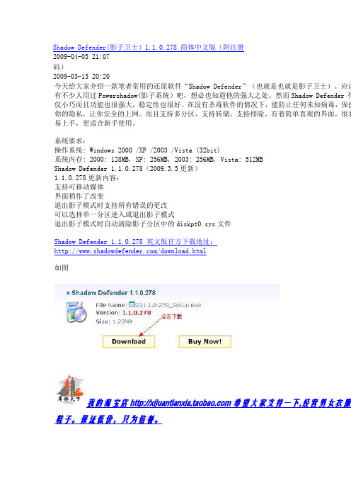
Shadow Defender(影子卫士)1.1.0.278 简体中文版(附注册2009-04-05 21:07码)2009-03-13 20:20今天给大家介绍一款笔者常用的还原软件“Shadow Defender”(也就是也就是影子卫士)。
应该有不少人用过Powershadow(影子系统)吧,想必也知道他的强大之处。
然而Shadow Defender不仅小巧而且功能也很强大,稳定性也很好。
在没有杀毒软件的情况下,能防止任何未知病毒,保护你的隐私,让你安全的上网。
而且支持多分区,支持转储,支持排除。
有着简单直观的界面,很容易上手,更适合新手使用。
系统要求:操作系统: Windows 2000 /XP /2003 /Vista (32bit)系统内存: 2000: 128MB, XP: 256MB, 2003: 256MB, Vista: 512MBShadow Defender 1.1.0.278(2009.3.5更新)1.1.0.278更新内容:支持可移动媒体界面稍作了改变退出影子模式时支持所有错误的更改可以选择单一分区进入或退出影子模式退出影子模式时自动清除影子分区中的diskpt0.sys文件Shadow Defender 1.1.0.278 英文版官方下载地址:/download.html如图我的淘宝店希望大家支持一下,经营男女衣服鞋子。
保证低价,只为信誉。
用汉化补丁替换安装目录下的 res.ini 文件即可。
默认安装目录:C:\Program Files\Shadow Defender注册码:24GAW-78SFC-DSPEG-E31U3-Z3TD7支持正版,成功注册后,如图:------------------------------------------------------------------------------------同时附上珍藏的免费版:Shadow Defender 1.1.0.275 简体中文免费版。
分析-去除天狼星视频加密系统的各种限制
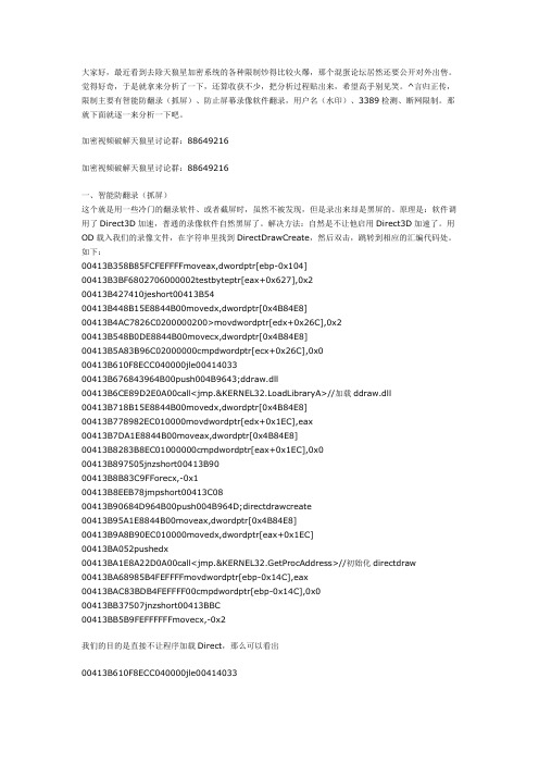
大家好,最近看到去除天狼星加密系统的各种限制炒得比较火爆,那个混蛋论坛居然还要公开对外出售。
觉得好奇,于是就拿来分析了一下,还算收获不少,把分析过程贴出来,希望高手别见笑。
^言归正传,限制主要有智能防翻录(抓屏)、防止屏幕录像软件翻录,用户名(水印)、3389检测、断网限制。
那就下面就逐一来分析一下吧。
加密视频破解天狼星讨论群:88649216加密视频破解天狼星讨论群:88649216一、智能防翻录(抓屏)这个就是用一些冷门的翻录软件、或者截屏时,虽然不被发现,但是录出来却是黑屏的。
原理是:软件调用了Direct3D加速,普通的录像软件自然黑屏了。
解决方法:自然是不让他启用Direct3D加速了。
用OD载入我们的录像文件,在字符串里找到DirectDrawCreate,然后双击,跳转到相应的汇编代码处。
如下:00413B358B85FCFEFFFFmoveax,dwordptr[ebp-0x104]00413B3BF6802706000002testbyteptr[eax+0x627],0x200413B427410jeshort00413B5400413B448B15E8844B00movedx,dwordptr[0x4B84E8]00413B4AC7826C020*******>movdwordptr[edx+0x26C],0x200413B548B0DE8844B00movecx,dwordptr[0x4B84E8]00413B5A83B96C02000000cmpdwordptr[ecx+0x26C],0x000413B610F8ECC040000jle0041403300413B676843964B00push004B9643;ddraw.dll00413B6CE89D2E0A00call<jmp.&KERNEL32.LoadLibraryA>//加载ddraw.dll00413B718B15E8844B00movedx,dwordptr[0x4B84E8]00413B778982EC010000movdwordptr[edx+0x1EC],eax00413B7DA1E8844B00moveax,dwordptr[0x4B84E8]00413B8283B8EC01000000cmpdwordptr[eax+0x1EC],0x000413B897505jnzshort00413B9000413B8B83C9FForecx,-0x100413B8EEB78jmpshort00413C0800413B90684D964B00push004B964D;directdrawcreate00413B95A1E8844B00moveax,dwordptr[0x4B84E8]00413B9A8B90EC010000movedx,dwordptr[eax+0x1EC]00413BA052pushedx00413BA1E8A22D0A00call<jmp.&KERNEL32.GetProcAddress>//初始化directdraw00413BA68985B4FEFFFFmovdwordptr[ebp-0x14C],eax00413BAC83BDB4FEFFFF00cmpdwordptr[ebp-0x14C],0x000413BB37507jnzshort00413BBC00413BB5B9FEFFFFFFmovecx,-0x2我们的目的是直接不让程序加载Direct,那么可以看出00413B610F8ECC040000jle00414033可以完全跳过direct加载,那就改成jmp了。
本本摄像头巧变“隐形”监控器

本本摄像头巧变“隐形”监控器对于本本用户来说,最讨厌的事情就是别人未经自己许可就随意操作本本,这不仅会泄露隐私信息,而且会将您精心配制的系统搞得面目全非。
摄像头是本本的标配,除了视频聊天外,其实还用l AVMonitor这款独特的软件,将本本变成隐形监控器,可以监控非法使用者进行的拍照、录像、抓取桌面图片、监控麦克风信号等操作,让您清楚了了解究竟是谁在非法使用自己的本本。
l AVMonitor是一款多功能监控软件,提供了监控摄像头、监控桌面、监控麦克风等实用功能,可以将摄像头动态画面、桌面活动画面录制为视频或者捕捉为图片,将从麦克风输入的音频信号录制为声音文件等。
而且其提供了隐蔽运行功能,能够悄无声息执行监控操作。
这里我们仅仅分析如何通过摄像头隐蔽本电脑的使用情况。
在l AVMonitor主窗口(如图1)中点击菜单“Monitor”→“Switch To Profile”项,在分支菜单中勾选“Monitor Webcam and automatically capture activity with the motion detector”项,表示激活摄像头自动监控动态画面功能。
或者点击“Ctrl+Y”键,在打开窗口中的“Video source”列表中选择本本的摄像头设备,也可以激活摄像头自动监控功能。
在l AVMonitor主窗口中的“Monitor”面板中点击带有扳手图标的按钮,在监控设置窗口(如图2)中选择“Sensibility”项,在其右侧拖动滑块,可以设置监控的灵敏度,该值越小,灵敏度越高。
这样当l AVMonitor通过摄像头捕捉到动态画面后(例如有人坐在本机前操作),就可以将摄像头画面捕捉为图片保存起来,便于您之后查看。
如果选择“Only grab image”项,则可以在“Interval”栏中设置捕捉摄像头W面的时间间隔,1 AVMonitor可以按照预设周期自动捕获摄像头画面,该方法虽然比较笨,但是可以实现连续捕捉操作。
- 1、下载文档前请自行甄别文档内容的完整性,平台不提供额外的编辑、内容补充、找答案等附加服务。
- 2、"仅部分预览"的文档,不可在线预览部分如存在完整性等问题,可反馈申请退款(可完整预览的文档不适用该条件!)。
- 3、如文档侵犯您的权益,请联系客服反馈,我们会尽快为您处理(人工客服工作时间:9:00-18:30)。
Automatic Shadow Detectionand Removal from a Single Image Salman H.Khan,Mohammed Bennamoun,Member,IEEE,Ferdous Sohel,Member,IEEE,andRoberto Togneri,Senior Member,IEEEAbstract—We present a framework to automatically detect and remove shadows in real world scenes from a single image.Previous works on shadow detection put a lot of effort in designing shadow variant and invariant hand-crafted features.In contrast,ourframework automatically learns the most relevant features in a supervised manner using multiple convolutional deep neural networks (ConvNets).The features are learned at the super-pixel level and along the dominant boundaries in the image.The predicted posteriors based on the learned features are fed to a conditional randomfield model to generate smooth shadow ing the detected shadow masks,we propose a Bayesian formulation to accurately extract shadow matte and subsequently remove shadows.The Bayesian formulation is based on a novel model which accurately models the shadow generation process in the umbra and penumbra regions.The model parameters are efficiently estimated using an iterative optimization procedure.Our proposed frameworkconsistently performed better than the state-of-the-art on all major shadow databases collected under a variety of conditions.Index Terms—Feature learning,Bayesian shadow removal,conditional randomfield,convnets,shadow detection,shadow mattingÇ1I NTRODUCTIONS HADOWS are a frequently occurring natural phenome-non,whose detection and manipulation are important in many computer vision(e.g.,visual scene understanding) and computer graphics applications.As early as the time of Da Vinci,the properties of shadows were well studied[1]. Recently,shadows have been used for tasks related to object shape[2],[3],size,movement[4],number of light sources and illumination conditions[5].Shadows have a particular practical importance in augmented reality applications, where the illumination conditions in a scene can be used to seamlessly render virtual objects and their casted shadows. Contrary to the above mentioned assistive roles,shadows can also cause complications in many fundamental com-puter vision tasks.For instance,they can degrade the performance of object recognition,stereo,shape reconstruc-tion,image segmentation and scene analysis.In digital pho-tography,information about shadows and their removal can help to improve the visual quality of photographs. Shadows are also a serious concern for aerial imaging and object tracking in video sequences[6].Despite the ambiguities generated by shadows,the Human Visual System(HVS)does not face any real diffi-culty infiltering out the degradations caused by shadows. We need to equip machines with such visual comprehen-sion abilities.Inspired by the hierarchical architecture of the human visual cortex,many deep representation learning architectures have been proposed in the last decade.We draw our motivation from the recent successes of these deep learning methods in many computer vision tasks where learned features out-performed hand-crafted fea-tures[7].On that basis,we propose to use multiple convolu-tional neural networks(ConvNets)to learn useful feature representations for the task of shadow detection.ConvNets are biologically inspired deep network architectures based on Hubel and Wiesel’s[8]work on the cat’s primary visual cortex.Once shadows are detected,an automatic shadow removal algorithm is proposed which encodes the detected information in the likelihood and prior terms of the pro-posed Bayesian formulation.Our formulation is based on a generalized shadow generation model which models both the umbra and penumbra regions.To the best of our knowl-edge,we are thefirst to use‘learned features’in the context of shadow detection,as opposed to the common carefully designed and hand-crafted features.Moreover,the pro-posed approach detects and removes shadows automati-cally without any human input(Fig.1).Our proposed shadow detection approach combines local information at image patches with the local informa-tion across boundaries(Fig.1).Since the regions and the boundaries exhibit different types of features,we split the detection procedure into two respective portions.Separate ConvNets are consequently trained for patches extracted around the scene boundaries and the super-pixels.Predic-tions made by the ConvNets are local and we therefore need to exploit the higher level interactions between the neighboring pixels.For this purpose,we incorporate localS.H.Khan and M.Bennamoun are with the School of Computer Scienceand Software Engineering,The University of Western Australia,35Stirling Highway,Crawley,WA6009,Australia.E-mail:{salman.khan,mohammed.bennamoun}@.au.F.Sohel is with the School of Engineering and Information Technology,Murdoch University,90South St,Murdoch,WA6150,and the School ofComputer Science and Software Engineering,The University of WesternAustralia,35Stirling Highway,Crawley,WA6009,Australia.E-mail:f.sohel@.au.R.Togneri is with the School of Electrical,Electronic and ComputerEngineering,The University of Western Australia,35Stirling Highway,Crawley,WA6009,Australia.E-mail:roberto.togneri@.au.Manuscript received18Apr.2014;revised28Apr.2015;accepted20July2015.Date of publication28July2015;date of current version10Feb.2016.Recommended for acceptance by R.Collins.For information on obtaining reprints of this article,please send e-mail to:reprints@,and reference the Digital Object Identifier below.Digital Object Identifier no.10.1109/TPAMI.2015.24623550162-8828ß2015IEEE.Personal use is permitted,but republication/redistribution requires IEEE permission.See /publications_standards/publications/rights/index.html for more information.beliefs in a Conditional Random Field (CRF)model which enforces the labeling consistency over the nodes of a grid graph defined on an image (Section 3).This removes iso-lated and spurious labeling outcomes and encourages neighboring pixels to adopt the same label.Using the detected shadow mask,we identify the umbra (Latin meaning shadow ),penumbra (Latin meaning almost-shadow )and shadow-less regions and propose a Bayesian formulation to automatically remove shadows.We intro-duce a generalized shadow generation model which sepa-rately defines the umbra and penumbra generation process.The resulting optimization problem has a relatively large number of unknown parameters,whose MAP estimates are efficiently computed by alternatively solving for the param-eters (Eq.(26)).The shadow removal process also extracts smooth shadow matte that can be used in applications such as shadow compositing and editing (Section 4).A preliminary version of this research (which solely focuses on shadow detection)appeared in [9].In addition,the current study includes:(1)a new approach to estimate shadow statistics,(2)automatic shadow removal and shadow matte extraction,(3)a substantial number of additional experiments,analysis and limitations,(4)possible applica-tions in many computer vision and graphics tasks.2R ELATED W ORK AND C ONTRIBUTIONS2.1Shadow DetectionOne of the most popular methods to detect shadows is to use a variety of shadow variant and invariant cues to cap-ture the statistical and deterministic characteristics of shad-ows [10],[11],[12],[13],[14].The extracted features model the chromatic,textural [10],[11],[13],[14]and illumination [12],[15]properties of shadows to determine the illumina-tion conditions in the scene.Some works give more impor-tance to features computed across image boundaries,such as intensity and color ratios across boundaries and the com-putation of texton features on both sides of the edges [11],[16].Although these feature representations are useful,they are based on assumptions that may not hold true in all cases.As an example,chromatic cues assume that the tex-ture of the image regions remains the same across shadow boundaries and only the illumination is different.This approach fails when the image regions under shadows are barely visible.Moreover,all of these methods involve a con-siderable effort in the design of hand-crafted features for shadow detection and feature selection (e.g.,the use of ensemble learning methods to rank the best features [10],[11]).Our data-driven framework is different and unique:we propose to use deep feature learning methods to ‘learn the most relevant features’for shadow detection.Owing to the challenging nature of the shadow detection problem,many simplistic assumptions are commonly adopted.Previous works made assumptions related to the illumination sources [5],the geometry of the objects casting shadows and the material properties of the surfaces on which shadows are cast.For example,Salvador et al.[14]consider object cast shadows while Lalonde et al.[11]only detect shadows that lie on the ground.Some methods use synthetically generated training data to detect shadows [17].Techniques targeted for video surveillance applications take advantage of multiple images [18]or time-lapse sequences [19],[20]to detect er assistance is also required by many proposed techniques to achieve their attained performances [21],[22].In contrast,our shadow detection method makes absolutely ‘no prior assumptions’about the scene,the shadow properties,the shape of objects,the image capturing conditions and the surrounding envi-ronments.Based on this premise,we tested our proposed framework on all of the publicly available databases for shadow detection from single images.These databases con-tain common real world scenes with artifacts such as noise,compression and color balancing effects.2.2Shadow Removal and MattingAlmost all approaches that are employed to either edit or remove shadows are based on models that are derived from the image formation process.A popular choice is to physically model the image into a decomposition of its intrinsic images along with some parameters that are responsible for the generation of shadows.As a result,the shadow removal process is reduced to the estimation of the model parameters.Finlayson et al.[23],[24]addressed this problem by nullifying the shadow edges and reinte-grating the image,which results in the estimation of the additive scaling factor.Since such global integration (which requires the solution of a 2D Poisson equation [23],[25])causes artifacts,the integration along a 1D Hamilto-nian path [26]is proposed for shadow removal.However,these and other gradient based methods (such as [27],[28])do not account for the shadow variations inside the umbra region.To address this shortcoming,Arbel and Hel-Or [29]treat the illumination recovery problem as a 3D surface reconstruction and use a thin plate model to successfully remove shadows lying on curved surfaces.Alternatively,information theory based techniques are proposed in [25],[30]and a bilateral filtering based approach is recently proposed in [31]to recoverintrinsicFig.1.From left to right :Original image (a).Our framework first detects shadows (c)using the learned features along the boundaries (top image in (b))and the regions (bottom image in (b)).It then extracts the shadow matte (e)and removes it to produce a shadow free image (d).(illumination and reflectance)images.However,these approaches either require user assistance,calibrated imag-ing sensors,careful parameter selection or considerable processing times.To overcome these shortcomings,some reasonably fast and accurate approaches have been pro-posed which aim to transfer the color statistics from the non-shadow regions to the shadow regions (‘color transfer based approaches’ e.g.,[21],[32],[33],[34],[35]).Our proposed shadow removal algorithm also belongs to the category of color transfer based approaches.However,in contrast to previous related works,we propose a general-ized image formation model which enables us to deal with non-uniform umbra regions as well as soft shadows.Color transfer is also made at multiple spatial levels ,which helps in the reduction of noise and color artifacts.An added advantage of our approach is our ability to separate smooth shadow matte from the actual image.Several assumptions are made in the shadow removal lit-erature due to the ill-posed nature of recovering the model parameters for each pixel.The camera sensor parameters are needed in [23],[31].Multiple narrow-band sensor outputs for each scene are required in [31],while [2]employs a sequence of images to recover the intrinsic mbertian surface and Planckian lightening assumptions are made in [31].Though several approaches work just on a single image,they require considerable user interaction to identify either tri-maps [36],quad-maps [33],[34],gradients [37]or exact shadow boundaries [27],[28].Su and Chen [38]tried to minimize the user effort by specifying the complete shadow boundary from the user provided strokes.In con-trast,our framework does not require any form of user interac-tion and makes no assumption regarding the camera or scene properties (except that the object surfaces are assumed to be Lambertian).The key contributions of our work are outlined below:We propose a new approach for robust shadow detection combining both regional and across-boundary learned features in a probabilistic frame-work involving CRFs (Section 3).Our proposed method automatically learns the most relevant feature representations from raw pixel val-ues using multiple ConvNets (Section 3).We propose a generalized shadow formation model along with automatic color statistics modeling using only detected shadow masks (Sections 4.1and 4.2).Our proposed Bayesian formulation for the shadow removal problem integrates multi-level color transferand the resulting cost function is efficiently opti-mized to give superior results (Sections 4.3and 4.4).We performed extensive quantitative evaluation to prove that the proposed framework is robust,less-constrained and generalisable across different types of scenes (Section 5).3P ROPOSED S HADOW D ETECTION F RAMEWORKGiven a single color image,we aim to detect and localize shadows precisely at the pixel level (see block diagram in Fig.2).If y denotes the desired binary mask encoding class relationships,we can model the shadow detection problem as a conditional distribution:Pðy j x ;w Þ¼1Z ðw Þexp ðÀE ðy ;x ;w ÞÞ;(1)where,the parameter vector w includes the weights of the model,the manifest variables are represented by x where x i denotes the intensity of pixel i 2f p i g 1ÂN and Z ðw Þdenotes the partition function.The energy function is composed of two potentials;the unary potential c i and the pairwise potential c ij :E ðy ;x ;w Þ¼Xi 2Vc i ðy i ;x ;w i ÞþXði;j Þ2Ec ij ðy ij ;x ;w ij Þ:(2)In the following discussion,we will explain how we model these potentials in a CRF framework.3.1Feature Learning for Unary PredictionsThe unary potential in Eq.(2)considers the shadow properties both at the regions and at the boundaries inside an image,c i ðy i ;x ;w i Þ¼f r i ðy i ;x ;w r i Þzfflfflfflfflfflfflfflffl}|fflfflfflfflfflfflfflffl{regionþf b i ðy i ;x ;w bi Þzfflfflfflfflfflfflfflffl}|fflfflfflfflfflfflfflffl{boundary:(3)We define each of the boundary and regional potentials,f rand f b respectively,in terms of probability estimates from the two separate ConvNets,f r i Ày i;x ;w r i Á¼Àw r i log P cnn1ðy i j x r Þf b i Ày i ;x ;w b i Á¼Àw bi log P cnn2ðy i j x b Þ:(4)This is logical because the features to be estimated at theboundaries are likely to be different from the ones estimated inside the shadowed regions.Therefore,we traintwoFig.2.The proposed shadow detection framework.(Best viewed in color.)KHAN ET AL.:AUTOMATIC SHADOW DETECTION AND REMOVAL FROM A SINGLE IMAGE 433separate ConvNets,one for the regional potentials and the other for the boundary potentials.The ConvNet architecture used for feature learning con-sists of alternating convolution and sub-sampling layers (Fig.3).Each convolutional layer in a ConvNet consists of filter banks which are convolved with the input feature maps.The sub-sampling layers pool the incoming features to derive invariant representations.This layered structure enables ConvNets to learn multilevel hierarchies of features.The final layer of the network is fully connected and comes just before the output layer.This layer works as a traditional MLP with one hidden layer followed by a logistic regression output layer which provides a distribution over the classes.Overall,after the network has been trained,it takes an RGB patch as an input and processes it to give a posterior distri-bution over binary classes.ConvNets operate on equi-sized windows,so it is required to extract patches around desired points of inter-est.For the case of regional potentials,we extract super-pix-els by clustering the homogeneous pixels.1Afterwards,a patch (I r )is extracted by centering a t s Ât s window at the centroid of each superpixel.Similarly for boundary potentials,we first apply a Bilateral filter and then extract boundaries using the gPb technique [40].We traverse each boundary with a stride b and extract a t s Ât s patch at each step to incorporate local context.2Therefore,ConvNets operate on sets of boundary and super-pixel patches,x r ¼fI r ði;j Þg 1ÂjF slic ðx Þj and x b ¼fI b ði;j Þg 1ÂjF gPb ðx Þj brespectively,where j :j is the cardinality operator.Note that we include synthetic data (generated by artificial linear transformations [41])during the training process.This data augmentation is important not only because it removes the skewed class dis-tribution of the shadowed regions but it also results in an enhanced performance.Moreover,data augmentation helps to reduce the overfitting problem in ConvNets (e.g.,in [42])which results in the learning of more robust feature representations.During the training process,we use stochastic gradient descent to automatically learn feature representations in a supervised manner.The gradients are computed using back-propagation to minimize the cross entropy loss func-tion [43].We set the training parameters (e.g.,momentum and weight decay)using a cross validation process.The training samples are shuffled randomly before trainingsince the network can learn faster from unexpected samples.The weights of the ConvNet were initialized with randomly drawn samples from a Gaussian distribution of zero mean and a variance that is inversely proportional to the fan-in measure of neurons.The number of epochs during the train-ing of ConvNets is set by an early stopping criterion based on a small validation set.The initial learning rate is heuristi-cally chosen by selecting the largest rate which resulted in the convergence of the training error.This rate is decre-mented by a factor of y ¼0:5after every 20epochs.The ConvNet trained on boundary patches learn to sepa-rate shadow and reflectance edges while the ConvNet trained on regions can differentiate between shadow and non-shadow patches.For the case of the regions,the posteri-ors predicted by ConvNet are assigned to each super pixel in an image.However,for the boundaries,we first localize the probable shadow location using the local contrast and then average the predicted probabilities over each contour generated by the Ultra-metric Contour Maps (UCM)[40].3.2Contrast Sensitive Pairwise PotentialThe pairwise potential in Eq.(2)is defined as a combination of the class transition potential f p 1and the spatial transition potential f p 2:c ij ðy ij ;x ;w ij Þ¼w ij f p 1ðy i ;y j Þf p 2ðx Þ:(5)The class transition potential takes the form of an Ising prior:f p 1ðy i ;y j Þ¼a 1y i ¼y j ¼0if y i ¼y ja otherwise :&(6)The spatial transition potential captures the differences inthe adjacent pixel intensities:f p 2ðx Þ¼exp Àk x i Àx j k 2b x hk x i Àx j k 2i!;(7)where,hÁi denotes the average contrast in an image.Theparameters a and b x were derived using cross validation on each database.3.3Shadow Contour Generation Using CRF Model We model the shadow contour generation in the form of a two-class scene parsing problem where each pixel is labeled either as a shadow or a non-shadow.This binary classifica-tion problem takes probability estimates from the super-vised feature learning algorithm and incorporates them in a CRF model.The CRF model is defined on a grid structured graph topology,where graph nodes correspond to image pixels (Eq.(2)).When making an inference,the most likely labeling is found using the Maximum a Posteriori (MAP)estimate (y Ã)upon a set of random variables y 2L N .This estimation turns out to be an energy minimization problem since the partition function Z ðw Þdoes not depend on y :y üargmax y 2L NPðy j x ;w Þ¼argmin y 2L NE ðy ;x ;w Þ:(8)The CRF model proved to be an elegant source to enforce label consistency and the local smoothness over the pixels.However,the size of the training space (labeled images)makes it intractable to compute the gradient oftheFig.3.ConvNet architecture used for automatic feature learning to detect shadows.1.In our implementation we used SLIC [39],due to its efficiency.2.the step size is b ¼t s =4to get partially overlapping windows.434IEEE TRANSACTIONS ON PATTERN ANALYSIS AND MACHINE INTELLIGENCE,VOL.38,NO.3,MARCH 2016likelihood.Therefore the parameters of the CRF cannot be found by simply maximizing the likelihood of the hand labeled shadows.Hence,we use the ‘margin rescaled algo-rithm’to learn the parameters (w in Eq.(8))of our proposed CRF model (see Fig.3in [44]for details).Because our pro-posed energies are sub-modular,we use graph-cuts for mak-ing efficient inferences [45].In the next section,we describe the details of our shadow removal and matting framework.4P ROPOSED S HADOW R EMOVAL AND M ATTING F RAMEWORKBased on the detected shadows in the image,we propose a novel automatic shadow removal approach.A block dia-gram of the proposed approach is presented in Fig.4.The first step is to identify the umbra,penumbra and the corre-sponding non-shadowed regions in an image.We also need to identify the boundary where the actual object and its shadow meet.This identification helps to avoid any errors during the estimation of shadow/non-shadow statistics (e.g.,color distribution).In previous works (such as [21],[29],[34]),this process has been carried out manually through human interaction.We,however,propose a simple procedure to automatically estimate the umbra,penumbra regions and the object-shadow boundary.Heuristically,the object-shadow boundary is relatively darker compared to other shadow boundaries where differ-ences in light intensity are significant.Therefore,given a shadow mask,we calculate the boundary normals at each point.We cluster the boundary points according to the direction of their normals.This results in separate boundarysegments which join to form the boundary contour around the shadow.Then,the boundary segments in the shadow contour with a minimum relative change in intensity are classified to represent the object-shadow boundary.If %c b denotes the mean intensity change along the normal direc-tion at a boundary segment b of the shadow contour c ,allboundary segments s.t.%c b =%cmax 0:5are considered to cor-respond to the segments which separate the object and its cast shadow.This simple procedure performs reasonably well for most of our test examples (Fig.5).In the case where the object shadow boundary is not visible,no boundary por-tion is classified as an object shadow boundary and the shadow-less statistics are taken from all around the shadow region.In most cases,this does not affect the removal per-formance as long as the object-shadow boundary is not very large compared to the total shadow boundary.Algorithm 4.1.R OUGH E STIMATION (S ;N )1:h S ;h N Get histogram of color distribution in S ;N 2:g S ;g N Fit GMM on h S ;h N using EM algorithm 3:for each j 2½0;JdoChannel wise color transfer between corresponding Gaussians using Eqs :ð9Þ;ð10Þ:Get probability of a pixel =super Àpixel to belong to a Gaussian component using Eq :ð11Þ:Calculate overall transfer for each color channel using Eq :ð12Þ:8>>>>>><>>>>>>:4:Combine multiple transfers:C Ãðx;y Þ¼1J þ1P j C j ðx;y Þ5:Calculate probability of a pixel to be shadow or non-shadow:p S ðx;y Þ¼P K k ¼1v k S jD k Nðx;y Þj k Sk N6:Modify color transfer using Eq.(13)7:Improve result from above step using Eq.(14)return ð^Iðx;y ÞÞTo estimate the umbra and penumbra regions,the boundary is estimated at each point of the shadow contour by fitting a curve and finding the corresponding normal direction.This procedure is adopted to extract accurate boundary estimates instead of local normals which can result in erroneous outputs at times.We propagate the boundaries along the estimated normal directions until the intensity change becomes insignificant (Fig.6).This results in an approximation of the penumbra region.We then exclude this region from the shadow mask and the remaining region is considered as the umbra region.The region immediately adjacent to the shadow region,withFig.4.The proposed shadow removal framework:After the detection of the shadows in the image,we estimate the umbra,penumbra and object-shadow boundary .Given this information,a multi-level color transfer is applied to obtain a crude estimate of shadow-less image.This rough estimate is further improved using the proposed Bayesian formulation which estimates the optimal shadow-less image along with the shadow modelparameters.Fig.5.Detection of object and shadow boundary:We use the gradientprofile along the direction perpendicular to a boundary point (four sam-ple profiles are plotted on the anti-diagonal of above figure)to separate the object-shadow boundary (shown in red in lower right image).KHAN ET AL.:AUTOMATIC SHADOW DETECTION AND REMOVAL FROM A SINGLE IMAGE 435twice the width of the penumbra region is treated as the non-shadow region.Note that our approach is based on the assumption that the texture remains approximately the same across the shadow boundary.4.1Rough Estimation of Shadow-Less Image by Color-TransferThe rough shadow-less image estimation process is based on the one adopted by the color transfer techniques in [32]and [34].As opposed to [32],[34],we perform a multilevel color transfer and our method does not require any user input.The color statistics of the shadowed as well as the non-shadowed regions are modeled using a Gaussian mixture model (GMM).For this purpose,a continuous probability distribution function is estimated from the histograms of both regions using the Expectation-Maximization (EM)algorithm.The EM algorithm is initialized using an unsuper-vised clustering algorithm (k-means in our implementation)and the EM iterations are carried out until convergence.We treat each of the R,G and B channels separately and fit mixture models to each of the respective histograms.It is considered that the estimated Gaussians,in the shadow and non-shadow regions,correspond to each other when arranged according to their means.Therefore,the color transfer is computed among the corresponding Gaussians using the following pair of equations:D k S ðx;y Þ¼Iðx;y ÞÀm k Ss k S(9)C k ðx;y Þ¼m k N þs kN D S ðx;y Þ;(10)where DðÁÞmeasures the normalized deviation for eachpixel,S and N denote the shadow and non-shadow regions respectively.The index k is in range ½1;K ,where K denotes the total number of Gaussians used to approximate the his-togram of S .The probability that a pixel (with coordinates x;y )belongs to a certain Gaussian component can be repre-sented in terms of its normalized deviation:p k G ðx;y Þ¼jD k S ðx;y Þj XK k ¼11jD S ðx;y Þj þ!À1:(11)The overall transfer is calculated by taking the weightedsum of transfers for all Gaussian components:Cj ¼0ðx;y Þ¼X K k ¼1p k G ðx;y ÞC kðx;y Þ:(12)The color transfer performed at each pixel location (i.e.,at level j ¼0)using Eq.(12)is local,and it thus,does not accurately restore the image contrast in the shadowed regions.Moreover,this local color transfer is prone to noise and discontinuities in illumination.We therefore resort to ahierarchical strategy which restores color at multiple levels and combines all transfers which results in a better estima-tion of the shadow-less image.We therefore resort to a hier-archical strategy which restores color at multiple levels and combines all transfers which results in a better estimation of the shadow-less image (see Fig.7).A graph based segmen-tation procedure [46]is used to group the pixels.This clustering is performed at J levels,which we set to 4in the current work based on the performance on a small valida-tion set,where we noted an over-smoothing and a low computational efficiency when J !5.Since,the segment size is kept quite small,it is highly unlikely that the differ-ently colored pixels will be grouped together.At each level j 2½1;J ,the mean of each cluster is used in the color trans-fer process (using Eqs.(9),(10))and the resulting estimate (Eq.(12))is distributed to all pixels in the cluster.This gives multiple color transfers C j ðx;y Þat J different resolutions plus the local color transfer i.e.,C j ¼0ðx;y Þ.At each level,a pixel or a super-pixel is treated as a discrete unit during the color transfer process.The resulting transfers are integratedto produce the final outcome:C Ãðx;y Þ¼1J þ1P J j ¼0C j ðx;y Þ:This process helps in reducing the noise.It also restores a bet-ter texture and improves the quality of the restored image.It should be noted that our hierarchical strategy helps in suc-cessfully retaining the self shading patterns in the recovered image compared to previous works (Section 5.3).To avoid possible errors due to the small non-shadow regions that may be present in the selected shadow region S ,we calculate the probability of a pixel to be shadowed using:p S ðx;y Þ¼P K k ¼1v k S p k S ðx;y Þ,where v kS is the weight of Gaus-sians (learned by the EM algorithm)and p k S ðx;y Þ¼jD k N j =ðjD k S j þjD kN jÞ:The color transfer is modified as:C 0ðx;y Þ¼ð1Àp S ðx;y ÞÞI S ðx;y Þþp S ðx;y ÞC Ãðx;y Þ:(13)However,the penumbra region pixels will not get accurateintensity values.To correct this anomaly,we define a rela-tion which measures the probability (in a naive sense)of a pixel to belong to the penumbra region.Since the penumbra region occurs around the shadow boundary,we define it as:b S ðx;y Þ¼d ðx;y Þ=d max :The penumbra region is recovered using the exemplar based inpainting approach of Criminisi et al.[47].The resulting improved approximation of the shadow-less image is,^Iðx;y Þ¼ð1Àb S ðx;y ÞÞEðx;y Þþb S ðx;y ÞC 0ðx;y Þ;(14)where,E is the inpainted image.In our approach,the crude estimate of a shadow-less image (Eq.(14))is further improved using Bayesian estima-tion (Section 4.3,see Fig.8).But first we need tointroduceFig.6.Detection of umbra and penumbra regions:With the detected shadow map (second image from left ),we estimate the umbra and penumbra regions (rightmost image )by analyzing the gradient profile (fourth image from left )at the boundary points.436IEEE TRANSACTIONS ON PATTERN ANALYSIS AND MACHINE INTELLIGENCE,VOL.38,NO.3,MARCH 2016。
