GPR-2500AIS中文手册-V2
cc2500中文
第 1 页 共 61 页
z 对数据包导向系统的灵活支持:对同步 词汇插入的芯片侦测,地址检查,灵活 的数据包长度及自动 CRC 处理
z 可编程信道滤波带宽 z OOK 和灵活的 ASK 整型支持 z 2-FSK 和 MSK 支持 z 自动频率补偿可用来调整频率合成器
到接收中间频率 z 对数据的可选自动白化处理 z 对现存通信协议的向后兼容的异步透
第 2 页 共 61 页
目录 1 缩写词 ....................................................................................................................... 2 2 绝对最大等级 ........................................................................................................... 5 3 工作条件 ................................................................................................................... 5 4 电气规范 ................................................................................................................... 6 5 常规特性 .............................................................................................
2500中文说明
ASTRO卫星XTS 2500Ⅲ型91ARS的用户登录和文本消息功能注:我在大写模式),多挖掘键将只有滚动大写字母。
(例如:一个,“乙->的C -”2)ii)在数字锁定模式下,按下键盘会只输入数字位数。
随后按相同的键位会插入相同的文本消息(没有多抽头)。
表三:键盘字符关键是数按时间(正常模式)关键1 2 3 4 5 6 7 8 90 0或按住以切换普通文本进入模式,大写模式和Num Lock模式。
1 1。
,?!; @ _ - *#&$ / + = \“'()美国广播公司美国广播公司2 23高清3登士4 ghi 4 GHI5 jkl 5 JKL6 6 MNO的二氧化锰7 PQRS的7 PQRS的德国TUV德国TUV 8 89 wxyz 9 WXYZ*空间#删除一个字符ASTRO卫星XTS 2500Ⅲ型92ARS的用户登录和文本消息功能4寻址讯息按D addr的下面解决您的传出地址:|消息。
地址输入屏幕IMPT RQRP返回出现。
按U或V滚动地址列表。
或通过使用多抽头直接地址条目。
5附加一个优先级的报!或请求的答复地址:|在发送您的消息,您可以附加一个优先级的消息或请求回复您的信息。
IMPT RQRP返回按D下面IMPT到开启/关闭一个“优先”标志对于传出的信息。
一“优先”标志图标显示在顶部切换时,屏幕上。
见“TMS的地位的象征”第88页。
按E到下面RQRP打开/关闭“要求回复“图标传出消息。
“请求回复”状态图标显示在屏幕的顶部时,翻转的。
见“全方位维修计划地位的象征“第88页。
ASTRO卫星XTS 2500Ⅲ型93ARS的用户登录和文本消息功能注意:当您收到一份关于XTS 5000无线电消息与“请求回复”图标标记,你必须手动响应您已收到发件人该消息。
该系统将不会自动发送回的无线电接收通知等信息。
注:“优先”在信息标志不意味着消息将获得比其他高优先级的消息当它被传播。
这仅仅是一个迹象表明,可以嵌入到一个信息,让接收器知道这个消息是重要的。
MP1500 2000 2500说明书-V2.0

DSPPA MP1500 MP2000 MP2500 F A F4AL F6AL F8AL P1 38V 43V 51V
INPUT
LINK
~220 Hz/10A
纯后级广播功放
PPrree--aammpp. . MMPP99881111PP
7
89
10
11
or
or
AAnnootthheerr AAmmpp.. MMPPsseerireiess
Guangzhou DSPPA Audio Co. Ltd.
4
纯后级广播功放
公共广播系列
MP 1500 MP 2000 MP 2500
Public Address Amplifier
POWER
CLIP SIGNAL PROT TEMP
5
4
6
3
7
2
8
19Biblioteka 010VOLUME
MP2500
PROFESSIONAL AMPLIFIER
THIS EQUIPMENT TO RAIN OR MOISTURE.
为了减少火灾或触电的危险, 不要将设备放在能被雨淋或潮湿的地方. 广州市迪士普音响科技有限公司 Guangzhou DSPPA Audio Co.,Ltd.
BTG2500中英文使用说明书
BIRD-SA-2500A操作手册
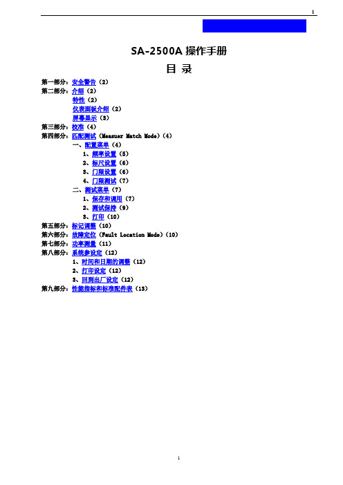
SA-2500A操作手册目录第一部分:安全警告(2)第二部分:介绍(2)特性(2)仪表面板介绍(2)屏幕显示(3)第三部分:校准(4)第四部分:匹配测试(Measuer Match Mode)(4)一、配置菜单(4)1、频率设置(5)2、标尺设置(6)3、门限设置(6)4、门限测试(7)二、测试菜单(7)1、保存和调用(7)2、测试保持(9)3、打印(10)第五部分:标记调整(10)第六部分:故障定位(Fault Location Mode)(10)第七部分:功率测量(11)第八部分:系统参设定(12)1、时间和日期的调整(12)2、打印设定(12)3、回到出厂设定(12)第九部分:性能指标和标准配件表(13)第一部分:安全警告1、测试时确定载频已关闭,天线不在工作状态。
2、清洁时请勿使用液体清洁济。
3、从存储的地方取出到温度相差很大的地方使用时,请勿马上开机使用,请先等温度正常后再开机使用。
第二部分:介绍BIRD site analyzer 是一台多功能测试仪表,适用于无线天线系统从工程安装到维护的全过程。
●特性:总述:SA2500A可抑制高达+13dBm的干扰信号。
存储60个带时间和日期标记的测试数据。
无须电脑,现场分析测试数据。
内置锂电池,方便野外使用。
可存储5个设置。
内置70种常用电缆规格和30个频率波段。
Measure Match模式:快速扫描测试。
预设通信系统频率波段,或用户自行选择开始/结束频率范围(横坐标)。
用户自行调整测量范围(纵坐标)。
可选择测量单位(回损、线损和VSWR)。
双标记读取,分析。
可设定通过/故障门限值。
同时显示多条迹线,并比较。
Fault Location 模式:用户自行选择开始/结束距离范围,自行选择距离单位英尺或米(横坐标)。
用户自行调整测量范围(纵坐标)。
可设定电缆规格(VP和Loss值)。
可设定通过/故障门限值。
●仪表面板介绍(图1):1、测试菜单(软键)键:根据不同的功能菜单,对应右边的显示实现不同的功能。
天调套件说明书V2
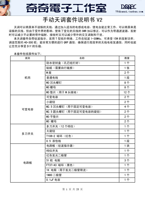
手动天调套件说明书V2天调可以将原来不谐振的天线,通过加入适当的电感或电容,使电台能正常工作。
可以将原来是谐振的天线,但由于受外界的影响,使有了变化的天线的SWR加以修正。
可以作为带通滤波器,发射时可以减少不必要的带外辐射,接收时又可以减少带外的交叉调制和干扰。
本天调套件自带驻波指示、采用T型拓扑网络,工作在短波1-30MHz,可承受15W的发射功率,调谐范围约40-300欧,能非常方便的进行QRP通信,确保进行高效率的无线电收发通信,同时也能让您充分享受DIY的乐趣。
本套件包括原件如下:类别 名称 数量机壳 防水密封盒(孔已经打好) 1个 贴纸(需要自行裁剪) 1张 M座 2个 普通电线 1段 M3沉头螺钉 8个 M3螺母 8个 M3垫片(用于M头接地) 12个可变电容 可变电容 2个 小旋钮 2个 M2.5沉头螺钉(用于固定可变电容) 4个 M2.5圆头螺钉(用于固定可变电容的旋钮) 2个 M3平垫片 2个 M3 螺母 2个多刀开关 多刀开关(12个档位) 1个 大旋钮 1个 T106-2 磁环(红色) 1个 0.5 漆包线 1段电路板 电路板(驻波指示器) 1块 档位开关 1个 红色发光二极管 1个 51欧 电阻 3个 FT37-43 磁环(黑色) 1个 1K 电阻(用于发光二极管限流) 1个 1N60二极管 1个 0.1uF电容 1个一、原理图动手制作之前,请仔细查阅这张图。
1、电路图如下:二、制作过程1、制作之前,请准备好烙铁、焊锡丝、剪刀、小刀、万用表等工具。
并根据原件表核对原件。
2、去除外壳内部多余塑料柱,位于下图的下方,建意先使用斜口钳子将塑料柱去剪掉,再使用电烙铁将多余部分烫平(注意不要烫太长时间,防止将整个塑料烫化,影响正面效果)。
3、安装两个M头到机壳。
安装过程中需要注意6个垫片的位置,它们的作用是理好的接地连接。
4、裁剪贴纸,贴于壳上。
效果图如下:两侧文字部分需要裁剪:5、安装可变电容及旋钮到外壳。
ioLogik 2500 Series (GPRS) 固件发布说明书

Firmware for ioLogik 2500 Series (GPRS) Release NotesSupported Operating SystemsNotesChangesApplicable ProductsBugs FixedN/A• Fixed where using FTP Upload action in Click&Go Plus triggers abnormal device reboot.• Fixed AI scaling result and web display error.• Fixed where using TCP Message action in Click&Go Plus triggers abnormal device reboot.EnhancementsN/AioLogik 2542-GPRS(-T), ioLogik 2512-GPRS(-T)N/ANew FeaturesN/AN/ASupported Operating SystemsNotesChangesApplicable ProductsBugs Fixed• Counter Value can be set by user through Modbus/TCP, AOPC, SNMP, RESTful API.• DO safe mode Hold Last function added.• ioLogik E1200 expansion unit connection status registers added.• ioLogik E1200 expansion unit auto-reconnection function added.• Unencrypted system log content added.• Fixed NTP only updates once for daylight saving time.• Fixed weekday and time zone mismatch issue.• Fixed counter initial value reset to 0 after counter scaling is enabled.• Fixed counter value reset to 0 when device is reconnected with MX-AOPC UA Server.• Fixed AI keyword replacement error for active messages from Click&Go Plus.• Fixed Click&Go DO lock issue when power on delay occurs.• Fixed unable to show special characters on web dashboard.• Fixed alias name with special characters issue.• Fixed AI on change update not triggered when variance<1.EnhancementsN/AioLogik 2512-HSPA, ioLogik 2512-HSPA-T, ioLogik 2542-HSPA, ioLogik 2542-HSPA-T• Modbus/TCP Master function.• RESTful API protocol support.• HTTPS support.• Counter power off storage function.• Counter overflow flag.• Service Setting to Enable/Disable all services on one page.• Access Control function for login attempt and lockout.• User Settings operator, user account enable/disable.• Password expiry time and notification configuration.• System use notification added on login page.• Internal registers BOOL and DWORD.• AOPC alive check for port 9500.New Features• Updated password requirements.N/ASupported Operating SystemsNotesChangesApplicable ProductsBugs Fixed• Improved device time accuracy.N/AEnhancementsN/AioLogik 2512-GPRS-T, ioLogik 2512-GPRS, ioLogik 2542-GPRS, ioLogik 2542-GPRS-TN/ANew FeaturesN/AN/ASupported Operating SystemsNotesChangesApplicable ProductsBugs FixedN/A• Fixed DO incorrect ON CHANGE status issue, which happened on Online Web interface, Modbus,AOPC, and Data Logging functions.• Fixed FTP Client return code (450) handling issue for FTP server.• Fixed Serial Mode setting mismatch (485-2W/422).EnhancementsN/AioLogik 2512-GPRS, ioLogik 2512-GPRS-T, ioLogik 2542-GPRS, ioLogik 2542-GPRS-T• Supports MXIO V3.0.• Supports MX-AOPC UA Logger data supplement function.• User Settings for three roles: Administrator, Operator, and User.• Access Control for allowing IP addresses to access through the Modbus protocol.• Three TC modes (78.126 mV, 39.062 mA, 19.532 mV) for ioLogik E1262 as I/O expansion.• Added “Power on Delay” settings for relay channels of ioLogik E1214 as I/O expansion.• Modbus address for raw value of AI, AO, TC, and RTD.• Modbus address for relay current count value, relay total count value, and reset relay current count value for ioLogik E1214 as I/O expansion.• Click&Go Plus IF condition for “relay current count value” and “total count value”.• Click&Go Plus Action for “Reset relay current count value”.• Modbus host connection timeout settings.• Click&Go Plus IF condition for “Modbus host connection status”.• Click&Go Plus IF condition for RTD and TC value comparison.• Enable/disable option for FTP server service.• Timestamp options (device local time or UTC and time zone) for data logging function.• Peer-to-Peer disconnection mode settings for DO and AO channels.• Communication timeout settings for FTP Client, Email, CGI Command Client, TCP Message, and Remote Action Client.• Checksum algorithm to improve correctness of configuration file transfer between IOxpress and Device.• Search device by IP address function.• Click&Go Plus IF condition for “Cellular link up”.• RSSI tag.• Added “Cellular IP” in keyword lookup options of SNMP trap, TCP/UDP message, email, and SMS.• Online web and configuration compatibility check, and guide user to import configuration through IOxpress.• Web server, FTP server, and Modbus TCP server connections in Network Connection status of Web Console.• Web console access rights by user type.New FeaturesN/AN/ASupported Operating SystemsNotesChangesApplicable ProductsBugs FixedN/A• Fixed a malfunction that occurs while importing configurations with empty rules to the device via the web.EnhancementsN/AioLogik 2512-GPRS, ioLogik 2512-GPRS-T, ioLogik 2542-GPRS, ioLogik 2542-GPRS-TN/ANew FeaturesN/AN/A。
AIS数字航标通信管理终端使用说明书
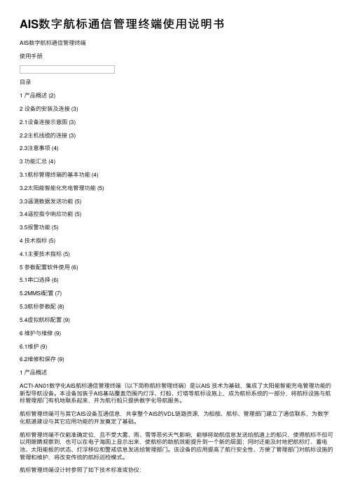
AIS数字航标通信管理终端使⽤说明书AIS数字航标通信管理终端使⽤⼿册⽬录1 产品概述 (2)2 设备的安装及连接 (3)2.1设备连接⽰意图 (3)2.2主机线缆的连接 (3)2.3注意事项 (4)3 功能汇总 (4)3.1航标管理终端的基本功能 (4)3.2太阳能智能化充电管理功能 (5)3.3遥测数据发送功能 (5)3.4遥控指令响应功能 (5)3.5报警功能 (5)4 技术指标 (5)4.1主要技术指标 (5)5 参数配置软件使⽤ (6)5.1串⼝选择 (6)5.2MMSI配置 (7)5.3航标参数配 (8)5.4虚拟航标配置 (9)6 维护与维修 (9)6.1维护 (9)6.2维修和保存 (9)1 产品概述ACTI-AN01数字化AIS航标通信管理终端(以下简称航标管理终端)是以AIS 技术为基础,集成了太阳能智能充电管理功能的新型导航设备。
本设备加装于AIS基站覆盖范围内灯浮、灯船、灯塔等航标设施上,成为航标系统的⼀部分,将航标设施与航标管理部门有机地联系起来,并为航⾏船只提供数字化导航服务。
航标管理终端可与其它AIS设备互通信息,共享整个AIS的VDL链路资源,为船舶、航标、管理部门建⽴了通信联系,为数字化航道建设与其它应⽤功能的开发奠定了基础。
航标管理终端不仅能准确定位,且不受⼤雾、⾬、雪等恶劣天⽓影响,能够将助航信息发送给航道上的船只,使得航标不但可以⽤眼睛观察到,也可以在电⼦海图上显⽰出来,使航标的助航效能提升到⼀个新的层⾯;同时还能及时地把航标灯、蓄电池、太阳能板的状态、灯浮移位和警戒信息发送给管理部门。
该设备的应⽤提⾼了航⾏安全性、⽅便了管理部门对航标设施的管理和维护,将改变传统的航标巡检模式。
航标管理终端设计时参照了如下技术标准或协仪:ITU-R M.1371-3:通⽤AIS技术特性;ICE 62320-2:AtoN设备技术规范;ICE 61162-1/2 Edition 2(NMEA 0183,Version 3.0):海上导航、通信设备及系统数字接⼝标准;ICE 60945 Edition 4:海上导航、通信设备及系统环境要求;ICE 61108-1:海上导航、通信设备及系统——GPS接收机技术规范;产品外观图如图1所⽰:图1 产品外观图2 设备的安装及连接2.1 设备连接⽰意图设备连接⽰意图如图2所⽰:太阳能板航标灯航标管理终端蓄电池图2 设备连接⽰意图2.2 主机线缆的连接航标管理终端对外接⼝由三组电源电缆与⼀组⼯作参数配置电缆组成,连接关系定义如表1~3所⽰。
EIP-2500项目器手册说明书
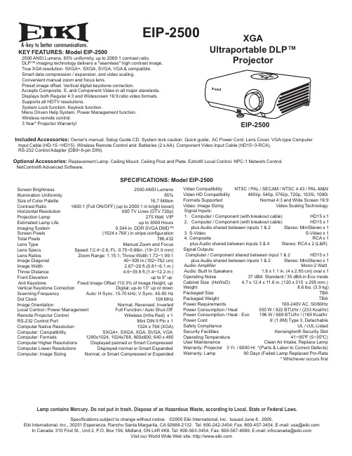
A EIP-2500KEY FEATURES: Model EIP-25002500 ANSI Lumens, 85% uniformity, up to 2000:1 contrast ratio.DLP™ imaging technology delivers a "seamless" high contrast image.True XGA resolution. SXGA+, SXGA, SVGA, VGA & compatible.Smart data compression / expansion, and video scaling.Convenient manual zoom and focus lens.Preset image offset. Vertical digital keystone correction.Accepts Composite, S, and Component Video in all major standards.Displays both Regular 4:3 and Widescreen 16:9 ratio video formats.Supports all HDTV resolutions.System Lock function. Keylock function.Menu Driven Help System. Power Management function.Wireless remote control.3 Year* Projector Warranty!Included Accessories: Owner's manual. Setup Guide CD . System lock caution. Quick guide. AC Power Cord. Lens Cover. VGA-type Computer Input Cable (HD-15 ~HD15). Wireless Remote Control and Batteries (2 x AA). Component Video Input Cable (HD15~3-RCA).RS-232 Control Adapter (DB9~8-pin DIN).Optional Accessories: Replacement Lamp. Ceiling Mount. Ceiling Post and Plate. Eztrol® Local Control. NPC-1 Network Control.NetControl® Advanced Software.SPECIFICATIONS: Model EIP-2500Screen Brightness 2500 ANSI Lumens Illumination Uniformity 85%Size of Color Palette 16.7 Million Contrast Ratio 1600:1 (Full ON/OFF) (up to 2000:1 in bright boost)Horizontal Resolution 600 TV Lines (DTV 720p)Projection Lamp 275 Watt VIP Estimated Lamp Life up to 3000 Hours Imaging System 0.544 in. DDR SVGA DMD™Screen Pixels (1024 x 768 ) in stripe configuration Total Pixels 786,432Lens Type Manual Zoom and Focus Lens Specs Speed: f:2.4~2.6; FL: 0.75~0.86in. (19~21.9 mm)Lens Ratios Zoom Range: 1.15:1; Throw:Width:1.72~1.99:1Image Diagonal 40~300 in.(102~762 cm)Image Width 2.67~20 ft.(0.81~6.1 m.)Throw Distance 4.6~39.8 ft.(1.4~12.2 m.)Front Elevation up to 9° up Anti Keystone Fixed Image Offset 110.3% of Image Height, up Vertical Keystone Correction Digital: up-to 13° up or down Scanning Frequency Auto: H Sync. 15-70 kHz; V Sync. 45-85 Hz Dot Clock 108 MHz Image Orientation Normal, Reversed, Inverted Local Control / Power Management Full Function / Auto Shut-Off Remote Projector Control Wireless (Infra Red) x 1 RS-232 Control Port Mini DIN 9 Pin x 1Computer Native Resolution 1024 x 768 (XGA)Computer: Compatibility SXGA+, SXGA, XGA, SVGA, VGA Computer: Formats 1280x1024, 1024x768, 800x600, 640 x 480Computer Higher Resolutions Displayed panned or Smart Compressed Computer Lower Resolutions Displayed normal or Smart Expanded Computer: Image Sizing Normal, or Smart Compressed or ExpandedVideo Compatibility NTSC / PAL / SECAM / NTSC 4.43 / PAL-M&N Video HD Compatibility 480i/p, 540p, 576i/p, 720p, 1035i, 1080i Formats Supported Normal 4:3 and Wide Screen 16:9Video: Image Sizing Video Scaling Technology Signal Inputs: 1. Computer / Component (with breakout cable) HD15 x 1 2. Computer / Component (with breakout cable) HD15 x 1 plus Audio shared between inputs 1 & 2 Stereo: MiniStereo x 1 3. S-Video S-Video x 1 4. Composite RCA x 1 plus Audio shared between inputs 3 & 4 Stereo: RCA x 2 (L&R)Signal Outputs: Compluter / Component shared between input 1 & 2 HD15 x 1 plus Audio shared between inputs 1 & 2 Stereo: MiniStereo x 1 Audio: Amplifier Mono:2 Watt Audio: Built In Speakers 1.6 x 1.1 in. (4 x 2.85 cm) oval x 1Operating Noise 37 dBA Standard / 35 dBA in Eco mode Cabinet Size (HxWxD) 4.7 x 12.4 x 11.6 in. (120 x 315 x 295 mm.)Weight 8.6 lbs. (3.9 kg)Packaged Size TBA Packaged Weight TBA Power Requirements 100-240V AC, 50/60Hz Power Consumption / Heat 350 W / 922 BTU/hr / (233 Kcal/hr)Power Consumption / Heat - Eco 196 W / 669 BTU/hr / (169 Kcal/hr Power Cord 6' (1.8M) Type 3, Detachable Safety Compliance UL / cUL Listed Security Facilities Kensington® Security Slot Operating Temperature 41~950F (5~350C)User Maintenance Clean Air Intake, Replace Lamp Warranty: Projector 3 Yr. / 6000 Hr. *(Parts & Labor to Correct Defects)Warranty: Lamp 90 Days (Failed Lamp Replaced Pro-Rata * Whichever occurs firstSpecifications subject to change without notice. ©2005 Eiki International, Inc. Issued June 8, 2005.EikiInternational,Inc.,30251Esperanza,RanchoSantaMargarita,CA92688-2132.Tel:800-242-3454;Fax:800-457-3454,E-mail:************In Canada: 310 First St., Unit 2, P .O.Box156,Midland,ONL4R4K8.Tel:800-563-3454,Fax:800-567-4069,E-mail:******************* Visit our World Wide Web site: Lamp contains Mercury. Do not put in trash. Dispose of as Hazardous Waste, according to Local, State or Federal Laws. EIP-2500XGA Ultraportable DLP™ Projector。
2500中文说明1

转译:BI7LAX注:本文是由翻译软件转制而成,个别内容未能贴题,请使用者自行理解,不便之处敬请原谅MotorolaASTRO卫星XTS 2500军用数字便携式收音机模型三用户指南,ASTRO卫星(R)的XTS 2500选择一个区域使用菜单发送无声紧急警报数字便携式收音机,Ⅲ型一按U,直到第一电台并按下紧急按钮。
你快速参考卡看不出有任何的LED,你听到没有声调。
产品安全和符合射频暴露2按D,E,或直接下区F。
2按对讲机。
注意!第一在使用本产品前,阅读区,直到你的愿望是显示的操作指令3按U。
!在产品安全和射频载三级安全使用继续进行,直到您退出:ç欧雄曝光小册子附上您的收音机。
4按H确认,或按对讲机传送。
*按住一个紧急按钮注意!第二这台收音机是受限制的职业,以满足或只使用FCC射频能量暴露要求。
在使用这个选择频道*按对讲机了。
产品,阅读意识信息和射频能量在产品的安全性和射频方法1使用说明:使用选择旋钮曝光小册子附上你的收音机(在选择所需的区域摩托罗拉,把16 -出版零件编号6881095C98),以确保遵守射频能量暴露限值。
位置旋钮来选择想要的频道。
3位方法1:使用菜单接电话16位旋转开关选择钮一按U,直到陈一电话般响起,绿色指示灯闪烁,开/关/最高的按钮电话,米显示。
音量旋钮2按D,E,或直接下文F陈。
2按下呼叫按钮的响应。
顶侧置喇叭/麦克风按钮3按U频道,直到你的愿望是显示。
3按下PTT按键通话,释放听。
PTT按键显示4按H确认,或按对讲机传送。
4按H挂断电话。
菜单选择一侧的按钮1按钮发送紧急报警电话呼叫发送2 1电台的按钮并按下紧急按钮。
你一按U直到喷看到红色的LED应用按钮,你听到的短期,中期高亢 _ _ _ _ _ _ _(TMS的按钮)音。
首页按钮2按D,E,或直接下文F喷。
4路2屏幕显示紧急情况。
3按U或V滚动到的电话号码。
导航按键的键盘3当收到确认,你听到4按对讲机(或快速访问按钮,如果写下你的电台的编程功能,在四个声调,报警结束,电台退出编程)说话,松开听。
AIS使用及操作教学学习教案
第十页,共39页。
AIS操作性能(xìngnéng)及要求
● 主 动 、 连 续向他 船或岸 台自动 发送本 船的静 态和动 态信息 。 ● 能 接 收 特 定的轮 询呼叫 ,传输 附加的 安全信 息,并 进行处 理 。 ● 能 在 航 行 中或锚 定(máo dìnɡ)状 态 下 连续运 行。 ● 船 舶 识 别 :应采 用适当 的海上 移动服 务实体 号码( MMSI) 。
通知要求:
1、现阶段ECS设备要求 2000总吨以上的“四客一危”船舶在2011
年6月30日之前安装,对于未按要求配备设备的船舶一律要求开航(kāi
háng)前纠正,复查合格后方可签证放行。
2、现阶段AIS设备要求100总吨以上的所有船舶在2011年12月30日
之前安装(液货船无吨位限制,一律安装),对于未按要求配备设备的
第7页/共39页
第八页,共39页。
AIS通信(tōng xìn )技术
AIS系统是海上移动VHF波段采用TDMA技术交换数据的一种避 碰系统,该系统在161.975MHz和162.025MHz的两个频点即海上 VHF87B/88B频道上收发(shōufā)信号,并合成全球定位系统、电罗经 及自动舵、雷达、电子海图等数据按需要在显示器上显示船位、动态 等信息。
的目标船只
第22页/共39页
第二十三页,共39页。
画面及显示(xiǎnshì)功能
设备采用真彩色液晶显示屏,方便大角度 观察,有海图屏、电子罗盘屏、卫星状态 屏,连续按翻页键可以实现他们之间的转 换。
海图屏
海图屏可以显示全中国的海域及部分内 河(nèihé)流域电子地图,并可实现多级缩 放及任意移动和旋转海图,还可以实时显 示船只的当前位置第、23页速/共39页度、航向、渔区号; 目的地(或游标)所在位置、渔区号、目
thip2500中文手册(2021年整理精品文档)

thip2500中文手册编辑整理:尊敬的读者朋友们:这里是精品文档编辑中心,本文档内容是由我和我的同事精心编辑整理后发布的,发布之前我们对文中内容进行仔细校对,但是难免会有疏漏的地方,但是任然希望(thip2500中文手册)的内容能够给您的工作和学习带来便利。
同时也真诚的希望收到您的建议和反馈,这将是我们进步的源泉,前进的动力。
本文可编辑可修改,如果觉得对您有帮助请收藏以便随时查阅,最后祝您生活愉快业绩进步,以下为thip2500中文手册的全部内容。
9。
1机柜9.1。
1 IH设备9.1。
1—1 IH设备—功能说明这种两路高频发生器用于:•TS - 横向的密封(A502)•LS —纵封(A501)SA - 带涂药(7417)脉冲持续时间由PLC程序来控制。
功率电平设置TPOP显示位于控制。
三相400V和24V DC,供给发生器。
每个TPIH-2500系统主要由:•电位计(1)•TPIH2500发生器(2)同轴电缆(3)(4)阻抗变换器1电位2 TPIH2500发生器3同轴电缆4阻抗变压器TPIH2500发生器主要由:•输出1 X4(5)•输出2 X5(6)•串行连接5233(7)•24V连接X3(8)•400V连接X1(9)•多功能按钮(10)•LED状态指示灯(11)•液晶显示器(12)5输出16输出27串行连接8 24V连接9 400V连接10多功能按钮11 LED液晶显示器(LCD)12LED的描述有触电的危险!当400VAC绿色指示灯熄灭仍然可以有一个或两个连接器X1阶段上。
彩色标签含义绿色24 VDC,当有24v时24 V时.它关闭时,没有24。
绿色400 VAC当所有3相存在。
为OFF时,至少错过了一个3相.红色错误是ON时,一个或多个错误发生。
在这种情况下,上液晶显示,操作员可以读取错误发生。
为OFF时,有没有错误条件。
绿色输出1而发电机是通过发送功率输出1为ON为OFF时,输出1为无效。
2500lb.Winch用户手册与操作指南说明书
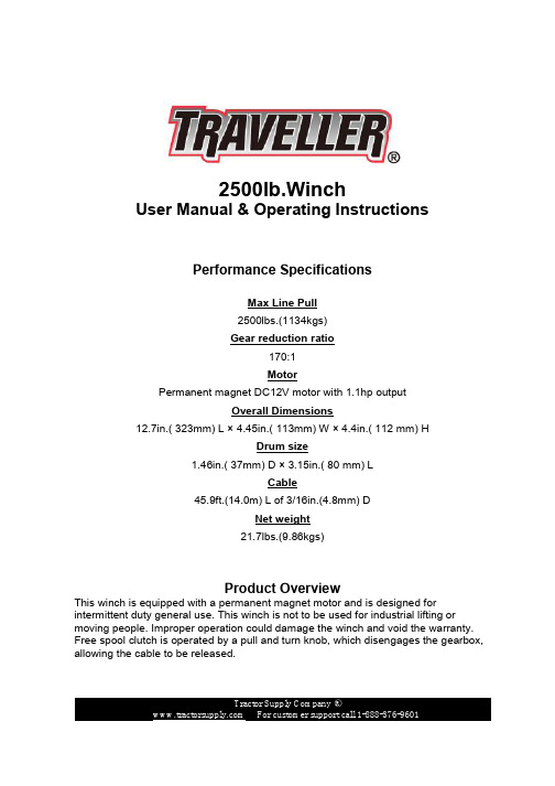
2500lb.WinchUser Manual & Operating InstructionsPerformance SpecificationsMax Line Pull2500lbs.(1134kgs)Gear reduction ratio170:1MotorPermanent magnet DC12V motor with 1.1hp outputOverall Dimensions12.7in.( 323mm) L × 4.45in.( 113mm) W × 4.4in.( 112 mm) HDrum size1.46in.( 37mm) D × 3.15in.( 80 mm) LCable45.9ft.(14.0m) L of 3/16in.(4.8mm) DNet weight21.7lbs.(9.86kgs)Product OverviewThis winch is equipped with a permanent magnet motor and is designed for intermittent duty general use. This winch is not to be used for industrial lifting or moving people. Improper operation could damage the winch and void the warranty. Free spool clutch is operated by a pull and turn knob, which disengages the gearbox, allowing the cable to be released.INSTALLATIONCorrect installation of the winch is required for proper operation.l Mount the winch on the mounting channel by using a screw(M8×16mm)(four sets). l Mount the winch with the mounting channel on the vehicle or other fixed installation by using a screw(M8×1.25×35mm), M8 nut, Φ8 flat washer and Φ8 spring washer(two sets).WARNING: This winch must be mounted with the cable in an under wound direction. Improper mounting could damage the winch and void the warranty.Connect the red wire to the positive terminal and the black wire to the negative terminal of the battery.(See Fig. 1).Fig. 1l Check the rotation direction of the drum. Pull and turn the clutch knob to the “FREE SPOOL” position (drum should turn freely by hand). Pull out some cable from the drum, and then turn the clutch knob to the “ENGAGE” position. Press the “OUT” button on the ATV/UTV switch; if the cable is releasing then it is properly connected. Otherwise reverse the wire connections to the motor, and repeat the above-mentioned operation.The ATV mountingThe UTV mountingOPERATIONl Pull and turn the clutch knob, so the drum can turn freely by hand.l Use hand saver bar to hitch the hook of the cable assembly and pull cable to the load. Attach the cable hook to the load.WARNING: Check that there are at least five turns of cable remaining on the drum before operation. Ensure the clutch knob is in the engaged position.CAUTION: Clutch must be fully engaged before winching.Never operate the clutch while drum is turning. Do not readjust clutch knob as it has been adjusted and permanently locked in place with a thread-locking compound in the factory.l Press the “IN” button on the ATV/UTV switch to re-spool the cable. Press the “OUT” button to reverse directions. Wait until the motor stops before reversing directions.l Re-spool the cable after completing the operation.REPLACING THE CABLEl Engage the clutch by turning the clutch knob to the “ENGAGE” position.l When inserting the cable into the drum, insert it into the correct end of the hole provided. Tighten the screws.l Operate the winch an re-spool the cable around the drum tightly.CAUTION: To keep the stated tension, be sure the cable is wrapped on the drum tightly.WARNING: Always replace damaged cable with manufacturer’s identical replacement part.MAINTENANCEl Periodically check tightness of mounting bolts and electrical connections. Remove all the dirt or corrosion and always keep clean.l Do not attempt to disassemble the gearbox. Repairs should be done by the manufacturer or authorized repair center.l The gearbox has been lubricated using high temperature lithium grease in the factory. No internal lubrication is required except when being repaired.TROUBLE SHOOTINGSYMPTOM POSSIBLE CAUSE SUGGESTED ACTIONMotor does not turn on -Switch Assembly notconnected properly-Insert switch assembly all the way into theconnector.-Loose battery cableconnections-Tighten nuts on all cable connections.-Defective switchassembly-Replace switch assembly.-Defective motor-Check for voltage at armature port with Switchpressed. If voltage is present, replace motor. -Water has enteredmotor-Allow to drain and dry. Run in short burstswithout load until completely dry.Motor runs butcable drum does not turn -Clutch not engaged-Turn clutch to the “In” position. If problempersists, a qualified technician needs to checkand repair.Motor runs slowly or without normal power -Insufficient current orvoltage-Battery weak recharge. Run winch with vehiclemotor running.-Loose or corroded battery cable connections.Clean, tighten, or replace.Motor overheating -Winch running timetoo long-Allow winch to cool down periodically.Motor runs in one direction only -Loose or corrodedbattery cable or motorcable connections.-Clean and tighten.WINCH ASSEMBLYWINCH PART LIST(2500LBS)No. Part # Qty Description1 P0250100 1 Motor Assembly2 P0250001 4 Locking Washer Φ83 P02500024 Cap Screw M8 x 164 P0250003 1 Transition Shaft5 P0250004 2 Tie Bar6 P0250005 1 Hexagonal Shaft7 P0250006 1 Front Bush Drum8 P0250007 6 Spring Washer Φ69 P0250008 1 Screw M6 x 810 P0250009 2 Cap Screw M6 x 7011 P0250010 1 Drum12 P0250011 1 Rear Bush Drum13 P0250012 1 Front Thrust Washer14 P0250013 1 Gear Ring Output15 P0250200 1 Gear Carrier Assembly16 P0250014 1 Gear Ring17 P0250015 1 Thrust Washer18 P0250016 1 Gear Housing / End Bearing19 P0250017 1 Bearing Holder20 P0250018 1 Roller Bearing21 P0250019 1 Clutch axes22 P0250020 1 Cam Clutch Gear23 P0250021 1 Spring24 P0250022 1 Cover Clutch Housing25 P0250023 1 Roller Bearing26 P0250024 1 Elastic Collar27 P0250025 1 Clutch Handle28 P0250026 1 Locking Washer Φ529 P0250027 1 Cap Screw M5 x 1230 P0250028 4 Cap Screw M6 x 2531 P0250029 4 Hex Flange Nut M832 P0250030 4 Locking Washer Φ833 P0250031 4 Thick Flat Washer Φ834 P0250300 1 Roller Fairlead35 P0250032 1 Mounting Channel36 P0250033 2 Cap Screw M8 x 2037 P0250034 2 Cap Screw M8 x3538 P0250035 1 Strap39 P0250400 1 Cable Assembly40 P0250036 2 Terminal Protector41 P0250500 1 Control AssemblySAFETY PRECAUTIONSl Never lift people or hoist loads over people. Do not lift items vertically, this winch is designed for horizontal use only.l Never overload. Be sure all equipment used meets the winch’s maximum line pull rating. When double-lining, pulley blocks should be rated for a minimum of two times the winch’s line pull rating.l Do not attempt prolonged pulls with heavy loads. The electric winch is designed for intermittent use only, and should not be used in a constant duty application.Never pull for more than one minute or exceed the rated load. If the winch motor becomes hot to the touch, stop the winch and allow it to cool down for several minutes.l Never operate winch with less than 5 turns of cable around the winch drum since the cable end may not withstand full load.l Avoid continuous pulls from extreme angles because this will cause the cable to gather on one end of the drum and damage the cable. Be aware that the winch’s line pull capacity is the max line pull of the first layer. Never operate winch pullinga load that exceeds the rated capacity.l Never hook the cable back to itself because it could damage the cable.l Be sure the winch is mounted securely on the vehicle or bracket before operation. l Before moving a load, inspect the cable. Prevent kinks and uneven cable layer before they occur. Apply proper tension to loads under 100lbs.l Do not move your vehicle to assist the winch in pulling the load. It will be easy to overload, and cause cable damage. Be aware of the danger zone. Keep away from the danger zone during the operation. The danger zone is the area of the winch drum, the fairlead (if fitted), the cable, the pulley block (if used), the hook, and the motor.l Never approach or span the cable when the winch is under load.l When using the winch to move a load, place the vehicle transmission in neutral, set vehicle brake, and chock all wheels. The vehicle engine should be running during winch operation so that battery has fully electricity. Never use the winch when there is a lack of voltage.l Never disconnect free spool cultch when there is a load on the winch.l Always stand clear of the cable, hook and winch. You should disconnect the clutch first, then use the hand saver bar to hitch the hook to pull the cable.l Inspect winch, cable, hooks and other accessories frequently. A frayed cable with broken strands should be replaced immediately. Use heavy leather gloves when handling the cable. Do not let the cable slide through your hands. Inspect thecable before use. Mashed , pinched, frayed or kinked areas severely reduce the load-carrying capability. Replacement cables must be re-spooled under 100lbs.l To keep stated tensile, re-spool the cable around the drum tightly after operation. l Do not operate winch when under the influence of drugs, alcohol or medication.Always stay alert during operation.l Wear eye protection and personal protective equipment while operating winch.l For loads over 50% of rated line pull, the use of the pulley block/snatch block to double the cable is recommended.l Do not operate around potentially flammable liquids, gases, or debris. Sparks may occur, resulting in the ignition of fire.Line speed and Motor current(First layer)Line PullLine Speedft./min (m/min)Motor CurrentAmpsIbs.(kgs) 12V DC 12V DC0 14.1(4.3) 20500(227) 9.8(3.0) 551500(680) 7.5(2.3) 952500(1134) 4.3(1.3) 160Line Pull And Cable CapacityLayer Rated line pull lbs (kgs) Total rope on the drum ft (m)1 2500(1134) 6.9(2.1)2 2033(922) 15.1(4.6)3 1713(777) 24.3(7.4)4 1480(671) 34.1(10.4)5 1303(591) 45.9(14.0)Distributed By:TRACTOR SUPPLY COMPANY5401 VIRGINIA WAY,BRENTWOOD, TN37027For customer support, call:1-888-376-9601MADE IN CHINA。
SAP1000 SAP2500 Active Probe 用户手册说明书

Use indoors only.
Keep product surfaces clean and dry.
Be careful with sharp tips. The tips may cause bodily injury if not handled properly.
2
SAP1000/SAP2500 Active Probe User Manual
1.1 Symbols
These symbols may appear on the probห้องสมุดไป่ตู้ body or in this manual to alert you to important safety considerations.
CAUTION. Potential for damage to probe or instrument it is connected to. Attend to the accompanying information to protect against personal injury or damage. Do not proceed until conditions are fully understood and met
Waves API 2500用户手册说明书

Waves API 2500 User ManualTABLE OF CONTENTSCHAPTER 1 – INTRODUCTION (3)1.1 W ELCOME (3)1.2 P RODUCT O VERVIEW (4)1.3 C ONCEPTS AND T ERMINOLOGY (5)1.4 C OMPONENTS (8)CHAPTER 2 – QUICKSTART GUIDE (9)CHAPTER 3 – CONTROLS AND INTERFACE (10)3.1 C OMPRESSOR S ECTION (10)3.2 T ONE S ECTION (12)3.3 L INK S ECTION (13)3.4 M ETER D ISPLAY (14)3.5 O UTPUT S ECTION (15)3.6 W AVESYSTEM T OOLBAR (16)APPENDIX A – API 2500 CONTROLS (17)Waves API 2500 User ManualChapter 1 – Introduction1.1 WelcomeThank you for choosing Waves! In order to get the most out of your new Waves plugin, please take a moment to read this user guide.To install software and manage your licenses, you need to have a free Waves account. Sign up at . With a Waves account you can keep track of your products, renew your Waves Update Plan, participate in bonus programs, and keep up to date with important information.We suggest that you become familiar with the Waves Support pages: /support. There are technical articles about installation, troubleshooting, specifications, and more. Plus, you’ll find company contact information and Waves Support news.Waves API 2500 User ManualWaves API 2500 User Manual1.2 Product OverviewThe API 2500 is a versatile dynamics processor that lets you shape the punch and tone of mixes with absolute accuracy. Its dual channel design lets the 2500 also function as two separate mono channels via a single compression setting. Using auto-makeup gain, you can adjust Threshold or Ratio while automatically maintaining a constant output level. With both Feed Back and Feed Forward compression types, the API 2500 boasts a wide range of incredibly musical parameters which have made it a favorite of engineers the world over.Waves API 2500 User Manual1.3 Concepts and TerminologyThere are 3 main parameters that set the API 2500 from other compressors: Thrust, Compression Type, and its adjustable Knee. When used in conjunction with one another, these parameters give the API 2500 unprecedented flexibility.KneeSets the knee, the manner in which the compressor begins to reduce the gain of the signal.• In the Hard position, gain reduction begins immediately at the set ratio.• In the Med position, there is a slight fade-in to the set ratio.• In the Soft position, there is an even more gradual fade-in to the set ratio.Waves API 2500 User ManualThrustSets the Thrust, a proprietary process that inserts a High Pass Filter at the RMS detector input, limiting compression response to lower frequencies while applying additional compression to higherfrequencies.• In Norm mode, there is no filter and the 2500 functions like a normal compressor.• In Med mode, there is a slight attenuation of the low frequencies and a slight boost of the highfrequencies, with a flat mid range affecting the signal into the RMS detector. This reducespumping caused by low frequencies and increases the RMS detectors’ sensitivity to higherfrequencies, affecting higher frequency signal peaks.• In Loud mode, a gradual linear filter attenuates level by 15dB at 20hz and increases level by15dB at 20khz. This decreases low frequency pumping while increasing higher frequencycompression.TypeSets the Compression type, which determines the signal source being fed to the RMS detector.• In New (Feed Forward) mode, the compressor works like newer VCA-based compressors. The RMS detector sends a signal to the VCA that is an exact ratio of the desired compression, set by the ratio control.• In Old (Feed Back) mode, the RMS detector receives a signal from the VCA output, and then feeds the VCA a signal based on the set signal ratio.Waves API 2500 User Manual1.4 ComponentsWaveShell technology enables us to split Waves processors into smaller plug-ins, which we call components. Having a choice of components for a particular processor gives you the flexibility to choose a configuration suitable for your material.The API 2500 has two component processors:API 2500 Stereo – A stereo compressor that may also be used as two parallel mono processors. API 2500 Mono – A mono compressor with an external sidechain option.Waves API 2500 User ManualChapter 2 – Quick Start GuideFor those of you who are experienced users of audio signal processing tools, we recommend that you approach the API 2500 as you would any compressor which you are already familiar. Keep in mind that its Thrust, Compression Type, and Knee parameters offer capabilities that transcend other, more conventional, processors.Newer users should explore the API 2500’s preset library and use its presets as starting points for their own experimentation. These presets also serve as a valuable introduction to compression techniques in general, and offer a glimpse into the workflow of professional audio engineers.We encourage all users to experiment with the API 2500’s settings in order to better understand its unique processing power.Waves API 2500 User ManualWaves API 2500 User ManualChapter 3 – Controls and Interface3.1 Compressor Section Tone Section Link Section Output SectionCompressor SectionWaveSystem Toolbar Meter SectionClip LEDThresholdS ets the point at which compression begins. Threshold for each stereo channel is set independently, since each channel has its own RMS detector, even in Link mode. In Auto Gain Make-up mode, the Threshold also affects the gain. Threshold is a continuous control.Range+10dBu to -20dBu (-12dBFS to -42dBFS)Default0dBuAttackSets the attack time of each channel.Range.03ms, .1ms, .3ms, 1ms, 3ms, 10ms, 30msDefault1msRatioSets the compression ratio of each channel. In Auto Gain Make-up mode, Ratio also affects the gain.Range1.5:1, 2:1, 3:1, 4:1, 6:1, 10:1, inf:1Default4:1ReleaseSets the Release time of the compressor. When set to Variable, Release time is controlled by the Variable Release control, located to the right of the Release control.Range.05sec, .1sec, .2sec, .5sec, 1sec, 2sec, VariableDefault.5secVariable ReleaseControls the release time with a continuously variable knob. (Please note: Release control must be set to Variable.)Range.05 seconds to 3 seconds in steps of 0.01msDefault.5secWaves API 2500 User Manual3.2 Tone SectionKneeSets the Knee, the manner in which the compressor begins to reduce the signal gain.RangeHard, Med, SoftDefaultHardThrustSets the Thrust, a proprietary process that inserts a High Pass Filter at the RMS detector input, limiting compression response to lower frequencies while applying additional compression to higher frequencies.RangeLoud, Med, NormDefaultNormTypeSets the Compression type, which determines the signal source being fed to the RMS detector.RangeFeed Back, Feed ForwardDefaultFeed ForwardWaves API 2500 User ManualA note about Sidechain:Sidechain lets you trigger the compressor using an external source, which is fed into the RMS detector and controls the compression of the input signal. Sidechain may only be used in New (Feed Forward) mode. An external sidechain trigger cannot be used in Old (Feed Back) mode; attempting to do so automatically switches the compressor to New (Feed Forward) mode.3.3 Link SectionL/R LinkSets the percentage of linkage between the left and right channels. While in Link mode, each channel is still controlled by its own RMS detector, which prevents loading and slaving from either side.RangeIND, 50%, 60%,70%,80%,90%,100%Default100%ShapeUses HP and LP filters to adjust the shape of L/R linking. This enables you to remove particularly high or low frequencies when adjusting the linking. Shape can be used, for example, to prevent percussive instruments on one channel from coupling and causing unwanted compression on the other channel. When HP and LP are both selected, a band pass filter is used to determine the shaping of L/R linking. Click on the Shape button to cycle between the four filter options.RangeHP, LP, BP (band pass), OffDefaultOffWaves API 2500 User Manual3.4 Meter DisplayMetersThe API 2500’s Meters display dBFS. The Gain scale displays the amount of gain reduction during compression with the 0 point located at the far the right, which allows higher gain reduction scale resolution.. The API 2500 is capable of up to 30dB of reduction.Range0dB to -24dB (Gain Reduction mode)-24dB to 0dB (Input and Output modes)Switchable Display ModesRangeGR, Out, InDefaultGRClip LEDBetween the two Meters is a Clip LED which indicates input or output clipping. Since the LED shows both input and output clipping, you must determine which of the two levels is excessive. The Clip LED can be reset by clicking on it.Waves API 2500 User Manual3.5 Output SectionAnalogTurns the Analog modeling on and off.RangeOn/OffDefaultOnOutputC ontrols the makeup gain.Range+/-24dBDefault0dBWaves API 2500 User ManualMake-UpTurns Auto Make-Up Gain on and off.RangeAuto, ManualDefaultAutoInActs as a master bypass for the entire compression chain. When set to Out, all compressor functions are bypassed.RangeIn/OutDefaultInMixC ontrols the balance between the compressed and the uncompressed signal.Range:0% to 100% (0.1% increments)Default:100%TrimSets the output level of the plugin.Range: -18 to +18 dB (in 0.1 dB steps)Initial Value: 0Reset Value: 03.6WaveSystem ToolbarUse the bar at the top of the plugin to save and load presets, compare settings, undo and redo steps, and resize the plugin. To learn more, click the icon at the upper-right corner of the window and open the WaveSystem Guide.Waves API 2500 User ManualAppendix A – API 2500 ControlsControl Range Default Threshold +10dBu to -20dBu 0dBu Attack .03ms, .1ms, .3ms, 1ms, 3ms, 10ms, 30ms 1ms Ratio 1.5:1, 2:1, 3:1 4:1 6:1 10:1 inf:1 4:1 Release .05sec, .1sec, .2sec, .5sec, 1sec, 2sec, Var .5sec Release Variable .05 to3sec in steps of 0.01ms .5sec Knee Hard, Med, Soft Hard Thrust Loud, Med, Norm Norm Type FeedBack, Feed forwards Feed Forwards L/R Link IND, 50%,60%,70%,80%,90%,100% 100% Link Filter Off, HP, LP, BP Off Make-up Auto, Manual Auto Meter GR, OUT, IN GR Analog On/Off 0degIn In/Out In Output +/-24dB 0dBMix 0–100% 100% Trim -18 dB to +18 dB 0dBWaves API 2500 User Manual。
Moxa ioLogik 2500 Series智能以太网远程I O说明书

ioLogik2500SeriesSmart Ethernet remote I/O with Click&Go Plus LogicFeatures and Benefits•Front-end intelligence with Click&Go Plus control logic,up to48rules•Active communication with MX-AOPC UA Server•Automatically complement disconnection period data with MX-AOPC UALogger software•4-port unmanaged switch built in for linking to Ethernet devices•I/O expansion port for daisy chaining up to8ioLogik E1200units•3-in-1serial port:RS-232,RS-422,or RS-485•Supports SNMP v1/v2c/v3•Simplifies I/O management with MXIO library for Windows or Linux•Wide operating temperature models available for-40to75°C(-40to167°F)environmentsCertificationsIntroductionioLogik2500smart Ethernet remote I/O devices feature unique hardware and software designs,making them ideal solutions for a variety of industrial data acquisition applications.The ioLogik2500’s hardware design includes a4-port unmanaged Ethernet switch and2serial ports, enabling it to seamlessly connect to a variety of field devices.One of the Ethernet ports can be used to link to8daisy-chained ioLogik E1200expansion modules to provide more than100channels.The ioLogik 2500acts as the“head”unit,with Click&Go Plus logic used to control the entire I/O array.Most importantly,a single IP is all that is required to connect the entire I/O array to your network,providing the perfect solution for industrial field sites that have an insufficient number of IP addresses. Programming-Free Click&Go Plus™LogicClick&Go Plus™control logic supports up to48rules and8conditions/actions.In addition,its graphical user interface provides3logic gates and3 multi-layers,helping you build more powerful and efficient IO solutions.Once you finish setting up your Click&Go Plus™logic rules,IOxpress’s easy-to-use simulation function can be used to find potential errors in your Click&Go Plus™rules before uploading them to your online devices. Multi-Protocol Data ConcentratorBy supporting multiple protocols,the ioLogik2500improves theefficiency of collecting field-site data and then sending it to upper-level systems.For field-site data collection,an ioLogik2500cancollect data from other third-party devices via both Modbus TCP andModbus RTU,and also lets you link up to8ioLogik E1200modules tocreate a versatile I/O array with over100different I/O channels,allowing all field-site data to be accessed by upper-level systems.Forthe upper-level systems,the ioLogik2500supports Modbus TCP,SNMP,SNMP Trap,RESTful API,Active OPC tag,and C++library foreasy integration with various IT/OT systems,making the ioLogik2500the perfect data concentrator for connecting field sites to yournetwork.Data Completeness with Local Storage Data LoggingThe ioLogik2500supports microSD cards,turning it into a powerful data logger for storing valuable data.Important data from field sites can be accessed remotely by different systems via an FTP,and the ioLogik's data completeness function enables real-time monitoring of data through MX-AOPC UA Suite when the network goes down unexpectedly.Remote Access Cellular I/O via Cellular NetworkMost carriers provide dynamic and private IP address SIM cards,andalthough private IP cards are cheaper,they cannot be used to providedirect access to the cloud.Moxa’s Cellular Data Access softwareenables this type of connection by establishing a special data routebetween the cellular models and the cloud.Only one public IP address is needed to use Moxa’s Cellular DataAccess software,allowing you to easily update internal registervalues,change output channel status,and modify the configurationsof devices connected to the device,all through the cloud.SpecificationsMemorymicroSD Slot Up to32GB(SD2.0compatible)Note:For units operating in extreme temperatures,industrial-grade,wide-temperaturemicroSD cards are required.Control LogicLanguage Click&Go PlusInput/Output InterfaceDigital Input Channels ioLogik2512Models:8Configurable DIO Channels(by software)ioLogik2512Models:8ioLogik2542Models:12Analog Input Channels ioLogik2542Models:4Buttons Reset buttonIsolation3k VDC or2k VrmsDigital InputsConnector Screw-fastened Euroblock terminalSensor Type Dry contactWet contact(NPN or PNP)I/O Mode DI or event counterDry Contact On:short to GNDOff:openWet Contact(DI to COM)On:10to30VDCOff:0to3VDCCounter Frequency 2.5kHzDigital Filtering Time Interval Software configurablePoints per COM ioLogik2512Models:8channelsioLogik2542Models:6channelsDigital OutputsConnector Screw-fastened Euroblock terminalI/O Type SinkI/O Mode DO or pulse outputCurrent Rating500mA per channelPulse Output Frequency5kHz(max.)DIO Output Leakage Current<1mA@30VDCOver-Current Protection 1.5A per channel@25°COver-Temperature Shutdown175°C(typical),150°C(min.)Over-Voltage Protection45VDC(typical)Analog InputsConnector Screw-fastened Euroblock terminalI/O Mode Voltage/CurrentI/O Type DifferentialResolution16bitsInput Range±10VDC0to10VDC0to20mA4to20mA4to20mA(with burn-out detection)Accuracy ioLogik2542Models(except-T):±0.1%FSR@25°C±0.3%FSR@-10to60°CioLogik2542-T:±0.1%FSR@25°C±0.3%FSR@-10to60°C±0.5%FSR@-40to75°CioLogik2542HSPA-T:±0.1%FSR@25°C±0.3%FSR@-10to60°C±0.5%FSR@-30to70°CSampling Rate All channels:400samples/secPer channel:100samples/secBuilt-in Resistor for Current Input120ohmsInput Impedance1mega-ohms(min.)Over-Voltage Protection-25to+30VDC(power on)-35to+35VDC(power off)Ethernet Interface10/100BaseT(X)Ports(RJ45connector)4,1MAC addressMagnetic Isolation Protection 1.5kV(built-in)Ethernet Software FeaturesConfiguration Options Web Console(HTTP/HTTPS),Windows Utility(IOxpress)Industrial Protocols CGI commands,Modbus TCP Client(Master),Modbus TCP Server(Slave),Moxa AOPC(Active Tag),MXIO Library,RESTful API,SNMPv1/v2c/v3,SNMPv1/v2c TrapManagement BOOTP,IPv4,SMTP,TCP/IP,DHCP ClientMIB Device Settings MIBSecurity HTTPS/SSLTime Management SNTPLED InterfaceLED Indicators ioLogik2512/2542Models:PWR,RDY,Serial port(P1,P2),Ethernet port(L1to L4),I/OChannel Status(0to15)ioLogik2512-HSPA/2542-HSPA Models:PWR,RDY,Serial port(P1,P2),Ethernet port(L1to L4),I/O Channel Status(0to15),Wireless connection,Signal StatusSerial InterfaceBaudrate300,1200,1800,2400,4800,7200,9600,19200,38400,57600,115200bps Connector8-pin RJ45Data Bits5,6,7,8Flow Control None,RTS/CTS,XON/XOFFNo.of Ports2Parity None,Even,OddSerial Standards RS-232,RS-422,RS-485Stop Bits1,2Serial SignalsRS-232TxD,RxD,RTS,CTS,DTR,DSR,DCD,GNDRS-422Tx+,Tx-,Rx+,Rx-,GNDRS-485-2w Data+,Data-,GNDRS-485-4w Tx+,Tx-,Rx+,Rx-,GNDSerial Software FeaturesIndustrial Protocols Modbus RTU MasterCellular InterfaceCellular Standards GSM,EDGE,GPRS,UMTS,HSPABand Options ioLogik2512-HSPA/2542-HSPA Models:UMTS/HSPA+800/850/900/1900/2100MHzUniversal quad-band GSM/GPRS/EDGE850/900/1800/1900MHzSIM Control Voltage 1.8V,3VSIM Format Mini SIMCellular Antenna Connectors ioLogik2512-HSPA/2542-HSPA Models:1SMA femaleSecurity FunctionsIPsec VPN ioLogik2512-HSPA/2542-HSPA Models:DES,3DES,AES-128,AES-192,AES-256 PlatformReal-time Clock(RTC)Real-time clock with capacitor backupPower ParametersPower Connector Screw-fastened Euroblock terminalNo.of Power Inputs1Input Voltage12to48VDCPower Consumption ioLogik2512/2512-T:254mA@24VDC,529mA@12VDC,133mA@48VDCioLogik2512-HSPA Models:352mA@24VDC,728mA@12VDC,187mA@48VDCioLogik2542/2542-T:281mA@24VDC,589mA@12VDC,144mA@48VDCioLogik2542-HSPA Models:311mA@24VDC,649mA@12VDC,166mA@48VDC Physical CharacteristicsHousing MetalIP Rating IP30Dimensions61x157x115mm(2.4x6.18x4.53in)Weight1,265g(2.79lb)Installation DIN-rail mounting,Wall mounting(with optional kit)Wiring I/O cable,16to26AWGPower cable,12to24AWGEnvironmental LimitsOperating Temperature Standard Models:-10to60°C(14to140°F)ioLogik2512-T/2542-T:-40to75°C(-40to167°F)ioLogik HSPA-T Models:-30to70°C(-22to158°F)Storage Temperature(package included)-40to85°C(-40to185°F)Ambient Relative Humidity5to95%(non-condensing)Altitude2000mStandards and CertificationsEMC EN61000-6-2/-6-4EMI CISPR32,FCC Part15B Class AEMS All Models:IEC61000-4-2ESD:Contact:4kV;Air:8kVIEC61000-4-4EFT:Power:1kV;Signal:0.5kVIEC61000-4-6CS:3VIEC61000-4-8ioLogik2512/2542Models:IEC61000-4-3RS:80MHz to1GHz:10V/mIEC61000-4-5Surge:Power:1kVioLogik2512-HSPA/2542-HSPA Models:IEC61000-4-3RS:80MHz to1GHz:3V/mIEC61000-4-5Surge:Power:2kVVibration IEC60068-2-6Shock IEC60068-2-27Freefall IEC60068-2-32Hazardous Locations ATEX,Class I Division2Safety UL508Radio EN301489-1/17Radio Frequency EN301908,EN301489-24,EN301511DeclarationGreen Product RoHS,CRoHS,WEEEMTBFTime ioLogik2512Models:467,032hrsioLogik2542Models:375,439hrsioLogik2512-HSPA Models:378,154hrsioLogik2542-HSPA Models:378,154hrsStandards Telcordia SR332WarrantyWarranty Period5yearsDetails See /warrantyPackage ContentsDevice1x ioLogik2500Series remote I/OCable2x RJ45-to-DB9console cableInstallation Kit1x cable holder with screw6x cap,plastic,for RJ45portAntenna1x UMTS/HSPA(HSPA models)Documentation1x quick installation guide1x warranty cardDimensionsOrdering InformationModel Name Input/Output Interface Wireless Standard Operating Temp. ioLogik25128x DI,8x DIO–-10to60°C ioLogik2512-T8x DI,8x DIO–-40to75°CioLogik2512-HSPA8x DI,8x DIOUMTS/HSPA+:five-band800/850/900/1900/2100MHzGSM/GPRS/EDGE:quad-band850/900/1800/1900MHz-10to60°CioLogik2512-HSPA-T8x DI,8x DIOUMTS/HSPA+:five-band800/850/900/1900/2100MHzGSM/GPRS/EDGE:quad-band850/900/1800/1900MHz-30to70°CioLogik25424x AI,12x DIO–-10to60°C ioLogik2542-T4x AI,12x DIO–-40to75°CioLogik2542-HSPA4x AI,12x DIOUMTS/HSPA+:five-band800/850/900/1900/2100MHzGSM/GPRS/EDGE:quad-band850/900/1800/1900MHz-10to60°CioLogik2542-HSPA-T4x AI,12x DIOUMTS/HSPA+:five-band800/850/900/1900/2100MHzGSM/GPRS/EDGE:quad-band850/900/1800/1900MHz-30to70°CAccessories(sold separately)SoftwareMX-AOPC UA Server OPC UA Server software for converting fieldbus to the OPC UA standardWall-Mounting KitsWK-51-01Wall mounting kit with2plates(51.6x67x2mm)and6screws©Moxa Inc.All rights reserved.Updated Mar14,2022.This document and any portion thereof may not be reproduced or used in any manner whatsoever without the express written permission of Moxa Inc.Product specifications subject to change without notice.Visit our website for the most up-to-date product information.。
Grandstream GAC2500 音频会议电话手册说明书

GrandstreamGAC2500Audio Conference Phone for Android TMQuick User GuideFor detailed information, please consult the GAC2500 User Manual available at Reproduction or transmittal of the entire or any part, in any form or by any means, electronic or print, for any purpose without the express written permission of Grandstream Networks, Inc. is not permitted. Information in this document is subject to change without notice. M AKE A C ALLe the leftmost screen or click Phone app to en-ter dial pad.2.Select a call mode on the left panel.3.Select account on the left panel.4.Enter the number to dial out and tap on dial soft-key .R EDIALWhen the phone has call history, click # key to redial.Notice: Redial via # key needs configuration on webUI.C ALL H OLDHold: During an active call, tap on softkey “Hold” onthe screen.Resume: When the call is on hold, tap on softkey“Unhold” on the screen to resume the call.C ALL T RANSFERBlind Transfer1.During an active call, tap on “More” softkey andselect “Transfer” to bring up the transfer screen.2.Select “Blind” on the upper left of the screen.3.Enter the digits and tap on “Send” softkey.Attended Transfer1.In a call, click Home key to dial screen. Dial se-cond number to establish another phone call. Thefirst call is on hold.2.When second call is established, tap on “More”softkey and select “Transfer” to bring up the trans-fer screen. The first call would display on the leftpanel.3.Click the dropdown on upper left and choose“Attended” mode. Then click the on hold call fromleft panel.4.The call is transferred, and it will hang up.S WITCH L INEWhen there are multiple calls, tap to tag on the top ofLCD to switch current to another.A DD TO C ONFERENCEIn a call, tap on “Add to conf” to bring all calls to a con-ference.E ND C ALLEnd a call by tapping on “End” softkey.R ECORD C ALL1.Tap on “Start recording” in a call to start recording.2.Tap on “End recording” to end recording.3.On LCD, open Recorder app to access the record-ing.A NSWER A C ALLAccount Incoming Call∙ Tap on “Answer” or “Reject” softkey to operatethe call.∙ Answer the second or later calls will hold allthe former calls.Conference Incoming Call∙ During the conference, the participants willhear a call waiting tone when there is an con-ference incoming call. The caller’s name andnumber would be shown on LCD.∙ Please choose the number first when there aremultiple incoming calls.∙ The new call will be added to the conference.Missed CallIf a call is not answered, LCD would displayMissed Call list. LED becomes flashing red. Userscan open Call History app to check missed calls.V OICEMAIL1.Swipe the LCD and tap on Voice Mail app.2.Select the account to access voice mails.Notice: The voice mail for an account is in LCDSettings -> Advanced settings -> Account (selectthe account)V OLUME A DJUSTMENTOn LCD, drag up from bottom to display menu bar.Tap on Volume Up or Volume Down to adjust thevolume.C ONFERENCE S CHEDULE1.Login to GAC2500 web UI -> Contacts ->Schedule, or tap on Schedule app.2.On LCD, tap on the softkey on upper right, orclick “New Conference” to create a new sched-ule.3.Fill the conference name, conference mem-bers, date, start time, duration, reminder, etc.∙ If “Auto Conference” is checked, GAC2500would automatically call other participants toinitiate the conference.M IXED C ONFERENCE(T HIRD-PARTY APP ANDSIP ACCOUNT LINES C ONFERENCE)Please make sure the device has installed andlogged in the third-party apps, such as Skype,Skype for Business (Lync 2013), etc.e the SIP account to initiate a conference.e dial pad to call the third-party app num-bers.3.When the call with third-party app is estab-lished, it will join the SIP account conference.4.Tap on the third-party app participant to openthe app for more operations.7-W A Y C ONFERENCEInitiate Conferencee the leftmost screen or click Phone app to en-ter dial pad.2.Select a call mode on the left panel.3.Select account on the left panel.4.Enter the number to dial out.5.Tap on the number from the list on the left, orchoose a number from Contacts.6.Repeat steps 4 and 5 to add up to 6 numbers.7.Tap on dial softkey and initiate the conference.Add Party1.Tap on the “add” icon in Conference app toopen a dial pad.2.Choose the call mode, account, and enter thenumber.3.Tap on call softkey.4.The callee will be added to the conference whenanswers.Participants OperationTap on participant icon to bring up more operations.Host can mute, block, delete a participant and checkhis information including whether to use SRTP or co-dec.Hold Conference1.Tap on Hold softkey to hold the conference.2.Tap on Hold softkey again to resume conference.Lock Conference1.Tap on Lock softkey to lock the conference.When the conference is locked, others cannot joinit.2.Tap on Lock softkey to unlock the conference.More OperationTap on “More” on bottom left in a conference to bringup more options. Host can record, mute, block the con-ference, open the DTMF dial pad and MPK, etc.End ConferenceTap on “End” on bottom right to end the conference.C ONTACTSTo open Contacts app, please tap on icon.C ALL H ISTORYTo enter Call History, swipe the screen left and rightand tap on icon.C ONFERENCE A SSISTANCE(B LUETOOTH/3.5MMAUX AND SIP ACCOUNT LINES C ONFERENCE)Please make sure the device has enabledBluetooth and connected with the cellphone. InGAC2500 Bluetooth settings, please enableheadset mode.1.Please use GAC2500 or cellphone to make acall.2.On GAC, open Conference app.3.Tap on add member softkey , Choose aSIP account and call the conference members.4.Then SIP accounts and cell phone would jointhe conference.Or, please make sure the cellphone is connectedto GAC2500 via 3.5mm aux cable.e cellphone to make a call.2.Tap on Conference app.3. Tap on add member softkey , Choose aSIP account and call the conference members.4. Then SIP accounts and cell phone would jointhe conference.Notice:∙ During a conference, turning off Bluetooth orunplugging 3.5mm AUX cable would causecommunication error.∙ Please choose the right line sequence whenusing 3.5mm AUX cable, otherwise GACwould not have audio.∙ When using the 3.5mm AUX cable with acellphone, GAC2500 cannot make a cellphonecall from LCD dial pad.∙ The audio quality may vary based on the3.5mm AUX cable or the connecting device.∙ When connected via 3.5mm AUX cable, somecellphone would be detected after the call isestablished.C ASCADE M ODETwo GAC2500 with cascade mode can be used ina larger room.1.Connect the 2 GAC2500 grey cascadeinterface with the RJ48 cable.2.Choose one device as a master from thepopup.e any device to operate the conference.R EQUIREMENTSTo make sure the best use of GAC2500, thefollowing requirements are necessary:1.Please do not move the device during a call.2.Please do not cover the device.3.Please face to the device when speaking.4.Please avoid an electric fan next to the device.5.To avoid any possible noise, please do not putthe laptop, projector, etc. next to the device.6.Unplug the power supply before cleaning. Donot use spray or corrosive liquids.。
- 1、下载文档前请自行甄别文档内容的完整性,平台不提供额外的编辑、内容补充、找答案等附加服务。
- 2、"仅部分预览"的文档,不可在线预览部分如存在完整性等问题,可反馈申请退款(可完整预览的文档不适用该条件!)。
- 3、如文档侵犯您的权益,请联系客服反馈,我们会尽快为您处理(人工客服工作时间:9:00-18:30)。
所有氧气传感器均对样气压力变化敏感。当流量变化控制在 1~5SCFH 之间时,其 引起的压力变化在分析仪的有效范围之内并且不会对分析仪的读数发生影响,尽管样 气流量的控制并不对变送器/分析仪的分析产生关键的影响,采用必要的流量控制装置 对样气流量进行控制仍然是必备的。我们推荐的适宜流量为 2 SCFH(1L 每分钟)。
2. 压力和流量: 入口压力:推荐 5~30psi,最大不要超过 100psi。 出口压力:应该排空,或接入其他管路但不能堵塞。
3.建立: A. 氧传感器:要试图打开传感器,因为传感器中含有腐蚀性液体,如果接触会对人 体有害,当传感器发生液体泄漏时应根据当地有关环保制度及时处理掉。 B. 安装:本仪器用于便携式测量或在室内固定安装使用,如果在室外安装需另配置 专门的经厂家推荐的外壳体。 C. 电源:本仪器利用可充电电池供电,应按手册所示给仪器充电,充电时最好使用 仪器提供的充电器,并保证仪器离火电插座有一定距离。充完电后切忌猛拉充电 器拽离插座或分析仪。 D. 温度:最大操作温度+45℃。 E. 热源:操作和存贮仪器时请远离发热热源。 F. 液体:分析仪不能被侵入任何液体中,也要小心液体或固体掉入分析仪中。 G. 操作:不要太用力拨仪器开关或阀门,移动仪器前要确保断开所有连接线。
此仪器的序列号(8 位)能够在分析仪外部找到,请您将该系列号填在本手册中下 面标注处,以此作为您的永久使用标识,并作为质保和维护的唯一标识。
序列号(Serial Number):
出于对用户最佳的使用及最小花费的考虑,此款仪器选用了最可靠的材料及元件 设计。此款仪器已经通过制造者完全的检验及检测,尽管如此,飞速发展的现代电子 设备始终是需要不断的维护,此手册提供的信息能够使您及时有效的维护您所购买的 分析仪表,并确保我们能够对每块售出仪表的有效保证。
电器特征
认 证:ISO9001,CE 认证。 防 爆:本安设计,加隔离栅可用于危险区:Class 1,Division 1,Groups B,C,D 显 示:大屏幕 LCD 显示,可实时显示样气压力和温度。 显示分辨率:当前量程的 0.1%(最小:0.001%) 控制键:防水按键,可方便地选择量程、校准等。。 补 偿:自动压力和温度补偿功能。 输 出:两线 4~20mA 模拟输出;可选配报警功能 电 源:9~28 V DC(加隔离栅时 24~28 V DC)。
物理特征
封装:氧化铝材质,NEMA 4X,壁挂式设计 体积:4” x 9” x3” 重量:8 lbs (约 3.5 公斤)
特殊应用
天然气等行业专用常量氧变送器—GPR-2500 AIS 适用于天然气,电厂,水煤气等行业 系统包括: —预处理单元, —核心仪表 GPR-2500 —报警单元 —H2S 吸附单元(选件)
-3-
第五章 操作
1)、测量原理
GPR-2500/25OOMO 变送器结合了多种燃料电池(电化学)式传感器的先进之处, 传感器原理相同并专门为氧纯度检测所设计的可检测 100%氧气含量,可应用于检测工 业应用中的氧气纯度。
作为电化学变换器燃料的氧气,在渗透进入传感器内部后,会在传感器的电极上 产生化学反应并在电极之间产生一个微小的电流,而这个电流的大小是和样气气路中 氧气的浓度大小相对应的。传感器的信号输出已在满量程范围内进行了线形化设定并 在整个使用寿命内保持稳定有效。传感器不需要进行维护,并且可方便的安全的在其 使用寿命到达后进行更换。
√
模拟信号输出 4 ~20mA 设置
√
气样测量: 量程校准并保证可调节范围在 0~50% FS
√
噪声水平:<±1.0%FS
√
最后:
外观无损和备件齐全
√
测试人签字和日期
-1-
第三章 安全常识及注意事项
1. 本节列出了所有仪器基本注意事项,专门的注意事项以后章节再单独说明,为了更好 的使用氧气仪器和获得最好性能指标,请认真阅读手册,熟悉操作办法,记住注意事 项,按照手册操作。以下本手册中经常用到两个提醒标志。 “Caution”:该标志提示用户一定按需求操作。 “Danger”: 该标志警告用户小心危险发生(如危险高压)
注意:建议采用厂家提供的取样系统,以获得更好的测量效果!
1、 将分析仪连接到气路上,必须确保出气口阀完全打开。 2、 将仪表前端流量控制阀的样气压力设定在 5~30psig 之间。 3、 将样气流量调节至 2 SCFH。 4、 选择能保证最大精度的量程档,直到分析仪的读数保持稳定。
安装顺序 a、旋开四角的的螺栓,将用于保护变送器/分析仪内部的面板取下。对于常用型可将其 完全移开以备重新安装。 b、常规应用型,将变送器/分析仪左侧的接线盒四角螺栓旋下。放置一旁以备重新安装。 注意!不要将变送器/分析仪盖和接线盒盖上的垫圈取下或丢弃。两者垫圈的任何错误 安装都会导致分析仪/变送器达不到 NEMA 标准规定的要求。 注意!此变送器/分析仪通过将特定的未涂绝缘漆的部分与组件的相应部位相结合的方 式,以保证传导。此方法为仪器提供 RFI 级别的保护。这些未涂镀区域由垫圈来保护。 c、注意不要将这些区域进行涂镀,否则将会破坏 RFI 保护。 d、一般应用型-将变送器/分析仪内部的安装定位空对准传感器组件下部,并将传感器上 部的 PCB 电缆连接,以固定传感器组件。 e、防爆型-安装脚在传感器组件外部。 f、拧紧相应的螺栓。 g、将变送器/分析仪安置在适合服务人员进行维护的垂直平面内。这需要再安装四个合 适尺寸的螺栓以便于固定。
目录
第一章 简介……………………………………………………………………2 第二章 出厂质量认证…………………………………………………………2 第三章 安全常识………………………………………………………………3 第四章 主要性能特点…………………………………………………………4 第五章 操作使用
5-1 操作原则 5-2 压力及流量 5-3 安装 5-4 校验 第六章 维护…………………………………………………………………… 6 第七章 常用备件清单………………………………………………………… 6 第八章 常见故障与处理办法………………………………………………… 6 第九章 仪器外观图、接线图、气路图……………………………………… 6 第九章 保修服务……………………………………………………………… 6
传感器: (×)GPR-11-120-RTS 氧传感器
序列号:(见英文手册)
附件:
用户手册
√
配置:
A-1112C-C PCB 主板
√
软件版本号
√
量程范围:(见英文手册)
√
电源:13~36VDC 两线制
√
封装:NEMA 4 壁挂式安装
√
压力补偿
√
电子测试: 预存出厂“零”点设置
√
预存出厂量程“SPAN”设置
设计和化学方面先进的专利技术的应用,使得氧气的传感检测技术附加了更独特 的先进性。氧气传感器的覆盖范围从纯度水平到空气水平再到 ppm 级水平,并且反应 时间均小于一分钟。在具有这些特点的同时,传感器同时具备了超长寿命和可靠质量。
GPR-25MO/25OOMO 分析仪所使用的 GPR -11-120-RTS 氧气纯度传感器,采用了 先进的传感器钝化技术对电化学式传感器进行钝化处理,克服了老式电化学式氧气传 感器在纯氧中消耗过快,造成传感器寿命过断。其正常的传感器寿命应为 24 个月左右。
注意:建议采用厂家提供的取样系统,以获得更好的测量效果!
-4-
气路注意事项: 1、 如分析仪已连接到气路上,必须确保出气口完全打开。 2、 确保进气气路畅通无障,防止对传感器形成抽真空状态。 3、 必须避免超压,特别是在样气排出不畅的情况下,会立刻损坏传感器。 4、 避免突然释放过高压力,否则会严重损坏传感器。 5、 确保没有灰尘、液体或气体凝结进入传感器,这些物质会影响氧气扩散进入传感器内
24 个月(XLT-11-24-4) 线性度:R 平方值>0.995 校准气:建议采用 80%量程 O2 in N2 标准气. 响应时间:10 秒达到 90%
操作条件
应用领域:制氢/制氮/CO2 设备,净化/干燥设备等 测量介质:H2、He、 CO2、混合气体、惰性气体等 接口:进出气口采用 1/8”卡套接头 压力:5~30psig 温度:5~+45℃(GPR 传感器),-20~+45℃(XLT 传感器) 流量:0.5~5 SCFH,推荐:2 SCFH(立方英尺/每小时)
部,使检测结果出现错误。
正压应用 推荐使用一个流量控制阀对将流量控制在 1~5 SCFH 之间。如需要在流量控制阀前端
连接一个压力调节装置用以调节样气压力。
负压应用 对于精确的 ppb 级、ppm 级和低的百分含量级检测,须在分析仪样气出口抽气泵,用
以将样气抽进仪器并通过传感器。而负压的真空度不能超过 1/4”水柱。此时仍须配置一 个流量控制阀用以控制流量在规定范围之内。在大气环境或轻微负压的应用中,抽气泵的 安装位置和抽气泵本身的气体泄露对于高百分含量的检测可以忽略不记。
第一章 简介
当您接收这款氧气分析仪时,欢迎您加入 ADVANCED 仪器的使用行列!此款全 新的百分含量氧气分析仪,能够确保您在多种工业应用中获得精确、长达数年的检测 结果。
此款氧气分析仪可用于检测惰性气体、气态碳氢化合物、氢气、多种混合气及酸 性气体中的氧气含量。
为了能够取得此款氧气分析仪的最大使用效果,请仔细阅读本手册,并按本手册 中的指导进行操作。
-2-
第四章 GPR-2500 主要性能特点
技术参数
量 程:0~1/5/10/25% 自动或手动调节 传感器:Galvanic 燃料电池—GPR-11-32-4
Galvanic 酸性电池—XLT-11-24-4 准确度:量程的 1%(在常温,常压下) 测量分辨力:量程的 0.5%(最小 0.005%) 传感器寿命:36 个月(GPR-11-32-4),
