TB358-RTD使用手册
taitron components lm358 双运算放大器 说明书.pdf
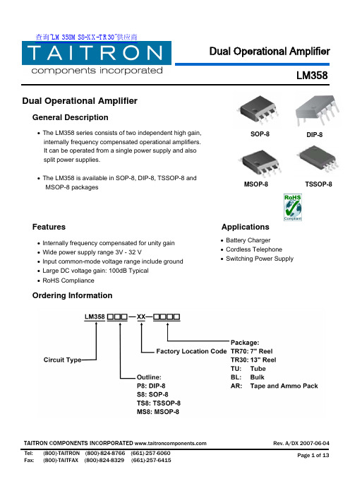
Dual Operational AmplifierGeneral Description• The LM358 series consists of two independent high gain, internally frequency compensated operational amplifiers. It can be operated from a single power supply and also split power supplies.• The LM358 is available in SOP-8, DIP-8, TSSOP-8 and MSOP-8 packagesFeatures Applications• Internally frequency compensated for unity gain•Wide power supply range 3V - 32 V• Input common-mode voltage range include ground• Large DC voltage gain: 100dB Typical • RoHS ComplianceOrdering InformationDIP-8SOP-8MSOP-8 • Battery Charger • Cordless Telephone • Switching Power SupplyTSSOP-8LM358 Internal Block DiagramSchematic DiagramLM358Absolute Maximum RatingsSymbol Description Ratings Unit V CC Supply Voltage±16 V V I(DIFF) Differential Input Voltage±32 V V I Input Voltage -0.3 ~ +32 V -Output Short to GroundContinuous-TSSOP-8 200MSSOP-8 200 SOP-8 280 P DPower DissipationDip-8 500mWT J Junction Temperature 125 ° C T OPR Operating Temperature Range 0 ~ +70 ° C T STGStorage Temperature Range-65~ +150° CNote: Absolute maximum ratings are those beyond which the device could be permanently damaged.Absolute maximum ratings are stress ratings only and functional device operation is not implied.Electrical Characteristics (V CC =5.0V, V EE =GND, T A =25ºC unless noted otherwise)LM358Symbol DescriptionMin.Typ.Max.Unit ConditionsV I(OFF) Input Offset Voltage - 2.9 7mVV CM =0V to V CC -1.5V V O(P)=1.4V,R S =0ΩV I(CM) Input Common Mode Voltage0 - V CC -1.5V V CC =30VV I(DIFF) Differential Input Voltage--V CC V-26 - -V CC =30V, R L =2K Ω V O(H)27 28 - VV CC =30V, R L =10K ΩV O(L) Output Voltage Swing- 5 20 mV V CC =5V, R L ≥10K Ω G VLarge Singnal Voltage Gain25100-V/mVV CC =15V, R L ≥2K ΩV O(P)=1V ~11VLM358Fig.1- Input Voltage RangePower Supply Voltage (V)Fig.2- Input Current vs. TemperatureTemperature (° C)LM358Symbol DescriptionMin. Typ. Max.Unit Conditions- 0.8 2.0 R L=∞, V CC=30VI CC Power Supply Current- 0.5 1.2mAR L=∞, Full TemperatureRangeI I(OFF)Input Offset Current - 5 50 nA -I BIAS Input Bias Current - 45 250 nA -I SCShort Circuit Current toGround- 40 60mA -I SOURCE10 30 - mAV I(+)=1V, V I(-)=0VV CC=15V, V O(P)=2V10 15 - mAV I(+)=0V, VI(-)=1VV CC=15V, V O(P)=2VI SINKOutput Current12 100 - µAV I(+)=0V, VI(-)=1VV CC=15V, V O(P)=200mV CMRRCommon Mode RejectionRatio65 80 - dB -PSRRPower Supply RejectionRatio65 100 - dB -CS Channel Separation - 120 - dB f=1KHZ ~ 20KHZ Typical Characteristics CurvesInputVoltage(V)InputCurrent(nA)LM358Fig.3- Input Current vs Supply VoltageSupply Voltage (V)I n p u t C u r r e n t (n A )Fig.5- Open Loop Frequency Response f – Frequency (Hz)Fig.4- Voltage Gain vs Supply VoltageSupply Voltage (V)V o l t a g e G a i n (d B )Fig.6- Common Mode Rejection Ratiof – Frequency (Hz)C o m m o n M o d e R e j e c t i o n R a t i o (d B )V o l t a g e G a i n (d B )LM358Fig.7- Voltage Follower Pulse Response t – Time (us) Fig.8- Voltage Follower Pulse Response(Small Signal)t – Time (us)O u t p u t V o l t a g e (m V )Fig.9- Gain vs Large Signal Frequency f – Frequency (Hz) O u t p u t V o l t a g e G a i n (V p -p )Fig.10- Output Current SinkingOutput Source Current (mA )V O - O u t p u t V o l t a g e (V )V O – O u t p u t V o l t a g e (V ) V I N – I n p u t V o l t a g e (V )LM358Typical ApplicationFig.11- Output Sink Current Output Sink Current (mA ) V O - O u t p u t V o l t a g e (V )Fig.12- Current Limiting vs TemperatureTemperature (° C)I O , O u t p u t S o u r c e C u r r e n t (m A )Fig.13- Battery ChargerLM358Typical Application (Continued)Fig.14- Power Amplifier Fig.15- DC Summing AmplifierFig.16- AC Coupled Non-Inverting Amplifier Fig.17- Fixed Current SourcesLM358Typical Application (Continued)Dimensions in inches (mm)Fig.18- Pulse GeneratorFig.19- DC Coupled Low-Pass Active FilterSOP-8LM358DIP-8TSSOP-8Dual Operational AmplifierLM358How to contact us:MSOP-8 查询"LM358MS8-XX-TR30"供应商。
泰特电子T800系列设备配套设备说明书
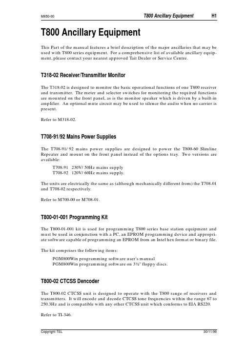
T800 Ancillary EquipmentThis Part of the manual features a brief description of the major ancillaries that may be used with T800 series equipment. For a comprehensive list of available ancillary equip-ment, please contact your nearest approved Tait Dealer or Service Centre.T318-02 Receiver/Transmitter MonitorThe T318-02 is designed to monitor the basic operational functions of one T800 receiver and transmitter. The meter and selector switches for monitoring the required functions are mounted on the front panel, as is the monitor speaker which is driven by a built-in amplifier. An optional mute circuit may be used to silence the audio when no carrier is present.Refer to M318-02.T708-91/92 Mains Power SuppliesThe T708-91/92 mains power supplies are designed to power the T800-60 Slimline Repeater and mount on the front panel instead of the options tray. Two versions are available:T708-91 230V/50Hz mains supplyT708-92 120V/60Hz mains supply.The units are electrically the same as (although mechanically different from) the T708-01 and T708-02 respectively.Refer to M700-00 or M708-01.T800-01-001 Programming KitThe T800-01-001 kit is used for programming T800 series base station equipment and must be used in conjunction with a PC, an EPROM programming device and appropri-ate software capable of programming an EPROM from an Intel hex format or binary file. The kit comprises the following items:PGM800Win programming software user's manualPGM800Win programming software on 3" floppy discs.T800-02 CTCSS DencoderThe T800-02 CTCSS unit is designed to operate with the T800 range of receivers and transmitters. It will encode and decode CTCSS tone frequencies within the range 67 to 250.3Hz and is compatible with any other CTCSS unit which conforms to EIA RS220. Refer to TI-346.T800-03 Auxiliary D-RangeThe T800-03 is an additional D-range kit comprising 1 D-range plug assembly, 1 D-range socket and 2 locating pins, nuts & washers.T800-04 RSSIThe T800-04 RSSI option PCB plugs directly into the main PCB (support circuitry being fitted as standard). It is fitted to the T855, T875 and T885 whenever receiver signal strength monitoring is required, e.g. trunking or voting. Its function is to provide a DC voltage proportional to the signal level at the receiver input.Refer to the appropriate service manual.T800-05 Guide RailThe standard T800 series guide with one D-range socket for mounting in the standard 483mm rack frame assembly.T800-06 External Frequency Reference KitThe T800-06 kit features an additional D-range plug which incorporates a miniature RF connector to carry an externally generated 12.8MHz reference signal into a T800 mod-ule. This enables the use of very high stability external reference oscillators for special applications.T800-07 Multichannel KitThe T800-07 is a plug-in multichannel memory PCB (supplied with connecting cable) which is intended as a substitute for the T800-10 memory PCB. Up to 128 channels may be addressed via the on-board DIP switch or remotely via the T800-03 D-range kit. CTCSS frequencies may also be stored alongside channel information within the EPROM.Refer to TI-356.T800-10 Memory ModuleThe T800-10 is the standard, plug-in T800 channel memory PCB.T800-13 Extender RailThe T800-13 extender rail allows a T800 unit to be operated out of the rack with the cov-ers off for tuning purposes. It is fitted with two 15-way D-range connectors.T800-14 Extender RailThe T800-14 extender rail allows a T800 unit to be operated out of the rack with the cov-ers off for tuning purposes. It is fitted with one 15-way D-range connector and one 11-way D-range incorporating a miniature RF connector for an externally generated ref-erence signal.T800-15 Speaker PanelA 60mm speaker panel fitted with a 4Ω speaker and complete with mounting hardware.T800-16 Speaker Panel (formerly T359-01)A 120mm speaker panel fitted with a 75mm x 125mm 4Ω speaker and complete with mounting hardware.T800-19 Rack Mounting FanThe T800-19 kit features a rack mounting fan which is designed to fit into the base of any standard 483mm rack frame without affecting its ability to house 7 modules. The kit contains all mounting hardware.T800-20 Pre-wired RackThe T800-20 is a standard 5U high rack which is wired to accommodate one 25, 50 or 100W base station or repeater. It comes complete with a T800-15 speaker panel and T992-01 blank panel.T800-21 Pre-wired Rack With Interface PCBThe T800-21 is a standard 5U high rack which is wired to accommodate one 25, 50 or 100W base station or repeater. It is also fitted with an interface PCB containing a 25-way D-range to allow the easy integration of OEM products into the base station or repeater configuration. The T800-21 comes complete with a T800-15 speaker panel and T992-01 blank panel.T800-30 & T800-35 DFSK ModulatorsThe T800-30 and T800-35 are DFSK modulators for T800 transmitters, suitable for POC-SAG or similar paging data formats. Analogue transmissions (e.g. tone or speech) are still possible by disabling the data path via a control line. 512 or 1200 baud data rates are link selectable. The T800-35 is adapted for use with an external reference oscillator for simulcast transmission.Refer to TI-373.T800-60 Slimline Repeater Mounting KitThe T800-60 Slimline Repeater kit enables one T800 receiver and one T800 transmitter to be mounted horizontally side-by-side in a standard 483mm rack frame. The kit contains a front panel complete with speaker, an options tray (for mounting a power supply, duplexer, etc.), and a wiring loom to connect the two T800 modules to the terminal blocks mounted on the rear of the options tray. The T708-91/92 mains power supplies (available separately) are designed for use with the T800-60. The rack height of the assembled unit is 2U.T800-80 Local MicrophoneA 600Ω microphone complete with 300mm cord terminated in a ¼" stereo plug.T800-81 Narrow Band Conversion KitThe T800-81 kit provides the components required to convert one T835 receiver from 25kHz channel spacing to 12.5kHz channel spacing for narrow band operation.T800-82 Narrow Band Conversion KitThe T800-82 kit provides the components required to convert one T836 transmitter or one T837 exciter from 5kHz deviation to 2.5kHz deviation for narrow band operation.T800-83 Narrow Band Conversion KitThe T800-83 kit provides the components required to convert one T855 receiver from 25kHz channel spacing to 12.5kHz channel spacing for narrow band operation.T800-84 Narrow Band Conversion KitThe T800-84 kit provides the components required to convert one T856 transmitter or one T857 exciter from 5kHz deviation to 2.5kHz deviation for narrow band operation.T801 Frequency Reference ModuleThe T801 frequency reference module provides a high stability frequency source to which the synthesiser within a T800 base station can be locked. The master standard within the T801 is primarily intended to be rubidium, although high quality ovenised crystal oscillators can also be used in applications where more frequent readjustment of frequency is acceptable. The T801 converts the output frequency from its master stand-ard to the 12.8MHz required by the T800 base station.Refer to M801-00.T801-10 OCXO ModuleThe T801-10 OCXO module provides a high stability frequency source to which the syn-thesiser within a T800 base station can be locked. This will provide T800 transmitters with the frequency stability required for simulcast transmission. The master standard within the T801-10 is a high quality ovenised crystal oscillator (OCXO). Three outputs are provided on the rear panel, which allows up to three T800 transmitters to be refer-enced to the source oscillator.T802-00 Remote MonitorThe T802-00 is a microprocessor controlled remote monitor unit designed for use with Tait base station equipment. Each remote base requires one T802-00 which communi-cates via its integral modem with a centrally located PC based controller. The PC con-troller runs software to convert the raw data from the T802-00 into a user friendly form. Refer to M802-00.T802-10 RF SplitterThe T802-10 RF splitters are used to take attenuated RF from the transmitter to the T802–00 where it is mixed onto the receiver frequency by the shift mixer. This RF is then inserted via another splitter into the receiver. Each T802-10 kit contains 2 identical RF splitter modules.Refer to M802-00.T802-20 Modem & Programming KitThe T802-20 kit provides a modem and the operating software for the T802-00 remote monitor PC controller and comprises the following items:a CCITT V.23 modemT802-00 PC software user's manualT802-00 PC software on a 5¼" floppy disc.T802-21 Programming KitThe T802-21 kit provides the operating software for the T802-00 remote monitor PC con-troller and comprises the following items:T802-00 PC software user's manualT802-00 PC software on a 5¼" floppy disc.T802-22 ModemA CCITT V.23 modem for use with the T802-00 PC controller.T806 Mains Power SupplyThe T806 is a power supply capable of supplying up to 6A at 11-14V DC and is available in 2 versions to suit a mains supply of either 230V/50Hz or 115V/60Hz (nominal val-ues). The T806 is designed to power T800 series 25W transmitters (plus receivers, etc.) and comes complete with a guide to mount in a standard 60mm rack frame assembly. Refer to M806-00.T807 Mains Power SupplyThe T807 is a switching power supply capable of supplying up to 15A at 11-14V DC. It requires a mains supply of 230V/50Hz or 115V/60Hz (nominal values) which can be internally selected with a switch or wire links. The T807 is designed to power T800 series 50W transmitters (plus receivers, etc.) and comes complete with a guide to mount in a standard 60mm rack frame assembly.Refer to M807-00.T808 Mains Power SupplyThe T808 is a switching power supply capable of supplying up to 25A at 11-14V DC. It requires a mains supply of 230V/50Hz or 115V/60Hz (nominal values) which can be internally selected with a switch or wire links. The T808 is designed to power T800 series 100W transmitters (plus receivers, etc.) and comes complete with a guide to mount in a standard 60mm rack frame assembly.Refer to M807-00.T1500-50 Trunking Extra D-Range (formerly T800-50)Trunking systems require additional outputs for flat audio (FFSK) and Rx line monitor-ing. This kit provides the components to connect these outputs via a second D-range.T1500-51 Trunking Transmitter Interface (formerly T800-51)When fitted to a T800 series transmitter, the T1500-51 trunking transmitter interface PCB allows the trunking system to switch the audio processor between FFSK and normal audio. The PCB comes complete with wires, sockets and screws, but a T800-03 auxiliary D-range kit will also be required.KS820 Spares KitThe KS820 spares kit contains all the parts on the T820 series recommended spares list and is intended to provided enough spares to maintain a single installation of up to ten channels. Included in the kit are electrical and mechanical parts that are either unique to Tait equipment, hard to obtain or susceptible to damage or wear and tear. All parts are securely packed in clearly labelled screw top containers in a handy plastic carry case.Note:The kit does not contain standard chip capacitors or resistors.KS830 Spares KitThe KS830 spares kit contains all the parts on the T830 series recommended spares list and is intended to provided enough spares to maintain a single installation of up to ten channels. Included in the kit are electrical and mechanical parts that are either unique to Tait equipment, hard to obtain or susceptible to damage or wear and tear. All parts are securely packed in clearly labelled screw top containers in a handy plastic carry case.Note:The kit does not contain standard chip capacitors or resistors.KS850 Spares KitThe KS850 spares kit contains all the parts on the T850 series recommended spares list and is intended to provided enough spares to maintain a single installation of up to ten channels. Included in the kit are electrical and mechanical parts that are either unique to Tait equipment, hard to obtain or susceptible to damage or wear and tear. All parts are securely packed in clearly labelled screw top containers in a handy plastic carry case.Note:The kit does not contain standard chip capacitors or resistors.KS880 Spares KitThe KS880 spares kit contains all the parts on the T880 series recommended spares list and is intended to provided enough spares to maintain a single installation of up to ten channels. Included in the kit are electrical and mechanical parts that are either unique to Tait equipment, hard to obtain or susceptible to damage or wear and tear. All partsare securely packed in clearly labelled screw top containers in a handy plastic carry case.Note:The kit does not contain standard chip capacitors or resistors.。
LM358中文资料(详细)教学文案

LM358中文资料LM358是常用的双运放,这里我们介绍一下它的一些资料以及简单电路应用。
简介:LM358里面包括有两个高增益、独立的、内部频率补偿的双运放,适用于电压范围很宽的单电源,而且也适用于双电源工作方式,它的应用范围包括传感放大器、直流增益模块和其他所有可用单电源供电的使用运放的地方使用。
LM358内部包括有两个独立的、高增益、内部频率补偿的双运算放大器,适合于电源电压范围很宽的单电源使用,也适用于双电源工作模式,在推荐的工作条件下,电源电流与电源电压无关。
它的使用范围包括传感放大器、直流增益模组,音频放大器、工业控制、DC增益部件和其他所有可用单电源供电的使用运算放大器的场合。
LM358的封装形式有塑封8引线双列直插式和贴片式。
〈lm358引脚图及引脚功能〉图1 DIP塑封引脚图引脚功能圆形金属壳封装管脚图内部电路原理图LM358的特性(Features):. 内部频率补偿. 低输入偏流. 低输入失调电压和失调电流. 共模输入电压范围宽,包括接地. 差模输入电压范围宽,等于电源电压范围. 直流电压增益高(约100dB). 单位增益频带宽(约1MHz). 电源电压范围宽:单电源(3—30V);. 双电源(±1.5 一±15V). 低功耗电流,适合于电池供电. 输出电压摆幅大(0 至Vcc-1.5V)参数输入偏置电流45 nA输入失调电流50 nA输入失调电压2.9mV输入共模电压最大值VCC~1.5 V共模抑制比80dB电源抑制比100dBLM358应用电路图:直流耦合低通RC有源滤波器LED驱动器TTL驱动电路RC有源带通滤波器Squarewave振荡器滞后比较器带通有源滤波器灯驱动程序电流监视器低漂移峰值检测器电压跟随器功率放大器外围电路电压控制振荡器VCO固定电流源脉冲发生器交流耦合反相放大器交流耦合非反相放大器可调增益仪表放大器直流放大器脉冲发生器桥式电流放大器引用差分输入信号直流差动放大器。
TB358-RTD接线端子板

TB358-RTD接线端子板1基本说明TB358-RTD端子板是16路热电阻信号输入端子板,供两块不冗余小量程模拟信号输入卡FW358作热电阻卡使用。
可测量16路三线制热电阻(Pt100或Cu50)信号。
2使用说明2.1端子板外观图TB358-RTD端子板结构外形如图 2-1 所示:图 2-1 TB358-RTD端子板结构外形图2.2接插件说明表 2-1 TB358-RTD端子板接插件说明标号说明J1 接线端子J2 第一块卡数据连线插座J3 第二块卡数据连线插座2.3三线制信号输入方式说明若热电阻信号为三线制输入方式,以A、B、C表示三线的热电阻接到端子板上的接线标号,假如我们把一个热电阻Rt接到FW358卡的第一通道上,那么接线端子1接A、端子2接B、端子3接C,如图2-2所示。
图 2-2三线制输入方式接线2.4端子定义及接线TB358-RTD接线端子说明如表 2-2所示:表 2-2接线端子说明描述端子号描述一号卡CH 1A 1 2 CH1B CH 1C 3 4 CH2A CH 2B 5 6 CH2C CH 3A 7 8 CH3B CH 3C 9 10CH 4ACH 4B 1112CH 4CCH 5A 1314CH 5BCH 5C 1516CH 6ACH 6B 1718CH 6CCH 7A 1920CH 7BCH 7C 2122CH 8ACH 8B 2324CH 8C二号卡CH 9A 2526CH 9B CH 9C 2728CH 10A CH 10B 2930CH 10C CH 11A 3132CH 11B CH 11C 3334CH 12A CH 12B 3536CH 12C CH 13A 3738CH 13B CH 13C 3940CH 14ACH 14B 4142CH 14C CH 15A 4344CH 15B CH 15C 4546CH 16A CH 16B 4748CH 16C 保护地端子4950保护地端子z端子号为1~24的接线端子连接第一块卡的信号线;端子号为25~48的接线端子连接第二块卡的信号线。
ISA-358G备自投说明书
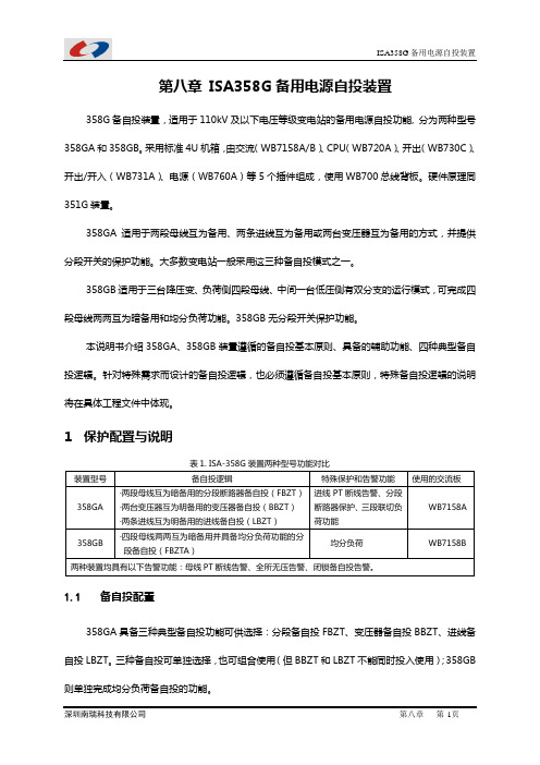
第八章ISA358G备用电源自投装置358G备自投装置,适用于110kV及以下电压等级变电站的备用电源自投功能, 分为两种型号358GA和358GB。
采用标准4U机箱,由交流(WB7158A/B)、CPU(WB720A)、开出(WB730C)、开出/开入(WB731A)、电源(WB760A)等5个插件组成,使用WB700总线背板。
硬件原理同351G装置。
358GA适用于两段母线互为备用、两条进线互为备用或两台变压器互为备用的方式,并提供分段开关的保护功能。
大多数变电站一般采用这三种备自投模式之一。
358GB适用于三台降压变、负荷侧四段母线、中间一台低压侧有双分支的运行模式,可完成四段母线两两互为暗备用和均分负荷功能。
358GB无分段开关保护功能。
本说明书介绍358GA、358GB装置遵循的备自投基本原则、具备的辅助功能、四种典型备自投逻辑。
针对特殊需求而设计的备自投逻辑,也必须遵循备自投基本原则,特殊备自投逻辑的说明将在具体工程文件中体现。
1保护配置与说明装置型号备自投逻辑特殊保护和告警功能使用的交流板358GA ·两段母线互为暗备用的分段断路器备自投(FBZT)·两台变压器互为明备用的变压器备自投(BBZT)·两条进线互为明备用的进线备自投(LBZT)进线PT断线告警、分段断路器保护、三段联切负荷功能WB7158A358GB ·四段母线两两互为暗备用并具备均分负荷功能的分段备自投(FBZTA)均分负荷WB7158B两种装置均具有以下告警功能:母线PT断线告警、全所无压告警、闭锁备自投告警。
1.1备自投配置358GA具备三种典型备自投功能可供选择:分段备自投FBZT、变压器备自投BBZT、进线备自投LBZT。
三种备自投可单独选择,也可组合使用(但BBZT和LBZT不能同时投入使用);358GB 则单独完成均分负荷备自投的功能。
1.2保护配置358GA装置装设的分段断路器保护设置三段,均可经取自两段母线电压的复合电压闭锁,其中后加速段保护可作为分段开关的充电保护:●限时电流速断保护●定时限过电流保护●后加速段保护1.3其它辅助功能告警功能则包括母线PT断线告警、全所无压告警、备自投闭锁告警。
浙大中控一 ECS 100系统介绍-8
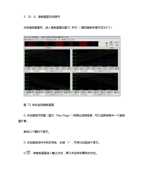
3.10.6、趋势画面浏览操作点击趋势图图标,进入趋势画面如图72 所示:(图的趋势布局方式为2*2)图72 实时监控趋势画面点击趋势页标题(图为“New Page”)将弹出选择菜单,可以选择将其中一个趋势图扩展,其他几个暂时不显示。
点击趋势控件中的位号名,去掉“√”,可使对应曲线不显示。
:使趋势画面进入静止状态,再次点击将恢复实时状态。
:显示前一页或后一页趋势画面。
:选择每次翻过一页的百分之几。
:减少和增加记录点数。
记录点数越多,趋势曲线越紧缩。
:选择在控件中显示哪个位号的纵坐标。
:时间和位号设置(图73 所示)。
图73 历史趋势时间和位号设置对话框起始时间、终止时间:用于选择需要查看的曲线段,在显示的有效范围内起始时间应比终止时间小100 秒以上。
时间间隔:单位为:时:分:秒,不能超过23:59:59。
数据点数:范围在100~1200 之间。
位置格式:可以选择在曲线图里面或是外面。
显示间隔:1~10 之间的整数。
终止时间-起始时间=时间间隔*数据点数。
:设置趋势图的显示特性。
如图74所示图74 趋势设置趋势布局:分别对一些选项进行选择,包括是否显示滑动条、工具条、数值坐标、时间坐标等以及显示的各位号信息进行设置。
数值坐标设置:对数值坐标的上下限及其他内容进行设置。
曲线图设置:对颜色、网格线及网格进行设置。
:趋势图画面刷新。
:打印属性设置,如图75 所示,设置完毕后,点击确定即可打印指定位号的趋势曲线。
图75 趋势图打印设置3.11、附录:系统各类卡件的功能、安装方法,拨码、跳线设置方法:1、主控卡FW243:地址范围2-31,周期100ms-5s2、主控卡FW243X:地址范围2-127,周期50ms-5s3、主控卡FW247:地址范围2-127,周期50ms-5s4、数据转发卡FW233地址范围0-155、数据转发卡FW233地址范围0-156、标准信号输入卡FW351:接收8路点点隔离的标准II、III型电压、电流信号。
东芝芯片资料
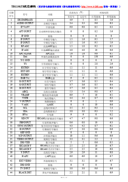
0 900Ω 600Ω 19.5K 15K 13K 19K
LA7833引脚功能
引脚
1 2 3 4 4 6 7
功能
接地端 场输出 自举升压电源端 场激励输入 负反馈输入及相位补偿 电源端 场逆程脉冲输出
直流电压
0V 13.6V 25.5V 0.8V 0.8V 26V 1.4V
纹波滤波电路引脚 第二伴音中频输出 调频直流反馈滤波电路引脚
电压
1.8V 0V 1.3V
+2.5V
+5V 2.45V 2.45V
1V 6.4V 0V 0V 2.3V 1.6V 0V +5V 3.6V 4.3V 0V 8V 8.8V 3.5V 5.6V 3.4V 3.5V
RXIK档对地电阻(黑表笔接地)
场AGC 总线时钟端子 总线数据端子
行电源 SECAM识别/载波信号输出
行逆程脉冲输入 复合同步信号输出 行激励信号输出
接地 沙堡脉冲输出 视频信号输出
数字电源
SECAM蓝色差信号输入 SECAM红色差信号输入
亮度信号输入 行AFC滤波
外接视频信号
接地 视频信Leabharlann 输入黑电平检测滤波直流电压(V)
有信号 4.9
800Ω 0
12.5K
12.8K
6K 13K 13K 13K 12.8K 13.2K
0 12.8K 13K 11.5K
1K 12.5K 12K
0 900Ω 600Ω 12.5K 12.2K 11.5K 12K
红笔接地 R×1K档
800Ω 0
19K
27K
5.5K 20K 20K 18K 28K 28K
NT358词典机 说明书
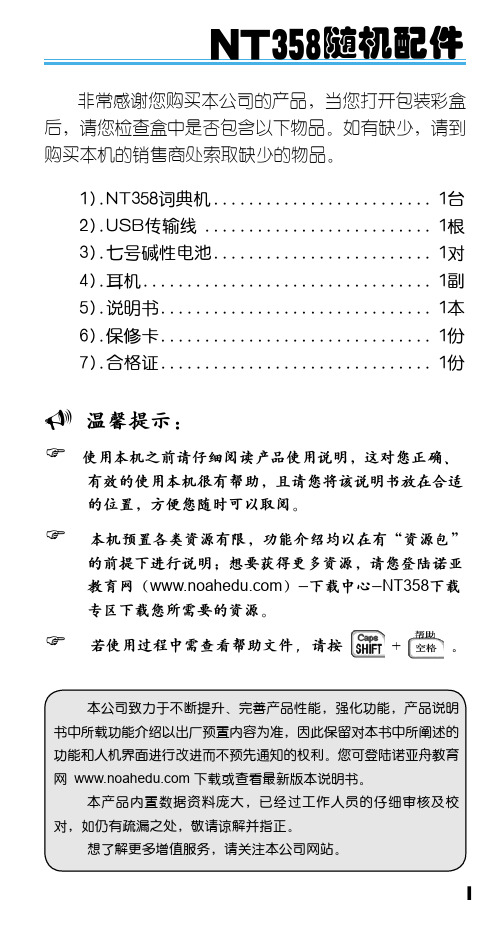
温馨提示:
使用本机之前请仔细阅读产品使用说明,这对您正确、 有效的使用本机很有帮助,且请您将该说明书放在合适 的位置,方便您随时可以取阅。 本机预置各类资源有限,功能介绍均以在有“资源包” 的前提下进行说明;想要获得更多资源,请您登陆诺亚 教育网()-下载中心-NT358下载 专区下载您所需要的资源。 若使用过程中需查看帮助文件,请按
在资料下载、系统升级过程中, 切勿进行按键操作,以免系统出 现错乱。
2
3
三 基本使用说明
1 开关机与系统复位
开关机:正常状态下,可按 键开、关机。 系统复位: 当系统由于意外 情况出现故障时(如操作出现异 常、出错、死机、没显示时), 在按键区右中边缘处有一个系统复 位键 ,只要用平头细物( 如笔尖)触及复位键 重新启动并恢复正常。 即可
请妥善保管本机,否则因您的私人 资料泄漏给他人所造成的损失,本 公司恕不负责。
当屏幕显示模糊不清(亮度调到最 大时)、闪烁、发音等不正常时应 及时更换电池。
避免猛烈的撞击。
不要使用钢笔、铅笔或其它尖锐物 品来按本机。
请另作备份所有重要资料,对因 操作不当,擅自维修等情况导致 机内资料丢失或损坏,本公司恕 不负责。
NT358随机配件
非常感谢您购买本公司的产品,当您打开包装彩盒 后,请您检查盒中是否包含以下物品。如有缺少,请到 购买本机的销售商处索取缺少的物品。 1).NT358词典机. ......................... 1台 2).USB传输线........................... 1根 3).七号碱性电池......................... 1对 4).耳机................................. 1副 5).说明书. ............................... 1本 6).保修卡. ............................... 1份 7).合格证............................... 1份
泰特电子T800系列II辅助设备服务手册说明书
M800-001T800 Series IIAncillary EquipmentService ManualIssue 101May 1998M800-00-1012M800-00T800Head OfficeNew ZealandTait Electronics Ltd558 Wairakei RoadP.O. Box 1645ChristchurchNew ZealandPhone: 64 3 358-3399Fax: 64 3 358-3636Radio Systems Division535 Wairakei RoadP.O. Box 1645ChristchurchNew ZealandPhone: 64 3 358-3399Fax: 64 3 358-2825AustraliaTait Electronics (Aust) Pty Ltd 186 Granite StreetGeebung Qld 4034P.O. Box 679VirginiaQueensland 4014AustraliaPhone: 61 7 3865-7799Toll Free: 1800 077-112Fax: 61 7 3865-7990CanadaTait Mobile Radio Inc.Unit 5, 158 Anderson Avenue MarkhamOntario L6E1A9CanadaPhone: 1 905 472-1100Toll Free: 1 800 890-8248 Fax: 1 905 472-5300FranceTait France Sarl2 Avenue de la Cristallerie92 316 Sèvres, CedexFrancePhone: 33 1 41 14-05-50Fax: 33 1 41 14-05-55GermanyT ait Mobilfunk GmbHWillstätterstraße 50D-90449 Nürnberg 60GermanyPhone: 49 911 96 746-0Fax: 49 911 96 746-79Hong KongTait Mobile Radio (HK) LtdRoom 703ANew East Ocean Centre9, Science Museum RoadT sim Sha Tsui EastHong KongPhone: 852 2369-3040Fax: 852 2369-3009New ZealandT ait Communications LtdUnit 4, 75 Blenheim RoadP.O. Box 1185ChristchurchPhone: 64 3 348-3301Fax: 64 3 343-0558SingaporeTait Electronics (Far East) Pte Ltd4 Leng Kee RoadSIS Building #05-11ASingapore 159088Phone: 65 471-2688Fax: 65 479-7778T aiwanTait Electronics (T aiwan) Ltd1104, No. 142 Chung Hsiao E. RdSec. 4TaipeiTaiwanPhone: 886 2 731-1290Fax: 886 2 711-6351ThailandTait Mobile Radio Ltd14/1 Suwan TowerGround FloorSoi Saladaeng 1North Sathorn RoadBangrakBangkok 10500ThailandPhone: 662 267-6290-2Fax: 662 267-6293United KingdomTait Mobile Radio LtdErmine Business ParkErmine RoadHuntingdonCambridgeshire PE18 6Y AUnited KingdomPhone: 44 1480-52255Fax: 44 1480-411996USATait Electronics (USA) Inc.9434 Old Katy RoadSuite 110HoustonTexas 77055USAPhone: 1 713 984-8684Toll Free: 1 800 222-1255Fax: 1 713 468-6944M800-003About This ManualScope This manual contains general, technical and servicing informa-tion on T800 Series II ancillary equipment.FormatWe have published this manual in a ring binder so that "revision packages" containing additional information pertaining to new issues of PCBs, or to additional ancillary equipment, can be added as required.Revision PackagesRevision packages will normally be published when an ancillary equipment manual requires overhaul, or to coincide with the release of information on a new PCB, and may also contain addi-tions or corrections pertaining to other parts of the manual.If you return the address card at the front of this manual, you will be notified when revision packages containing new PCB information and/or text are available. You may then order as many packages as you require from your local Tait Company .Revision packages are supplied ready-punched for inclusion in your manual.Revision ControlEach page in this manual has a date of issue. This is to comply with various Quality Standards, but will also serve to identify which pages have been updated and when. Each page and its publication date is listed in the "List of Effective Pages", and a new list containing any new/revised pages and their publica-tion dates will be sent with each revision package.Any portion of text that has been changed is marked by a verti-cal line (as shown at left) in the outer margin of the page. Where the removal of an entire paragraph means there is no text left to mark, an arrow (as shown at left) will appear in the outer mar-gin. The number beside the arrow will indicate how many para-graphs have been deleted.The manual issue and revision status are indicated by the last three digits of the manual IPN. These digits start at 100 and will increment through 101, 102, 103, etc., as revision packages are published, e.g:Thus, Issue 103 indicates the third revision to issue 1 and means that three packages should have been added to the manual. The issue digit will only change if there is a major product revision,or if the number of revision packages to be included means that the manual becomes difficult to use, at which point a new issue manual will be published in a new ring binder.PCB InformationPCB information is provided for all current issue PCBs, as well as all previous issue PCBs manufactured in production quanti-ties, and is grouped according to PCB. Thus, you will find the21 0 3issue statusrevision status4M800-00parts list, grid reference index (if necessary), PCB layouts andcircuit diagram(s) for each individual PCB grouped together. Errors If you find an error in this manual, or have a suggestion on howit might be improved, please do not hesitate to contact the Tech-nical Writer, Tait Radio Systems Division, Tait Electronics Ltd,P.O. Box 1645, Christchurch, New Zealand.Technical InformationAny enquiries regarding this manual or the equipment it describes should be addressed in the first instance to your nearest approved Tait Dealer or Service Centre. Further technical assistance may be obtained from the Customer Support Group, Radio Systems Division, Tait Electronics Ltd, Christchurch, New Zealand.Updating Equipment And ManualsIn the interests of improving performance, reliability or servicing, Tait Electronics Ltd reserve the right to update their equipment and/or manuals without prior notice. CopyrightAll information contained in this manual is the property of Tait Electronics Ltd. All rights are reserved. This manual may not, in whole or part, be copied, photocopied, reproduced, translated stored or reduced to any electronic medium or machine readable form without prior written permission from Tait Electronics Ltd.Ordering Tait Service ManualsService Manuals should be ordered from your nearest Tait Branch or approved Dealer. When ordering, quote the Tait Internal Part Number (IPN) and, where applicable, the version.Date Of IssueIPN M800-00-101T800 Series II Ancillary Equipment Service ManualIssue 101 published April 1998M800-00 5 Table Of ContentsThis manual is divided into three parts as listed below, with each part being further sub-divided into sections. There is a detailed table of contents at the start of each part and/or section.Part TitleA General Servicing ProceduresB T807/808 Switching Power SupplyC T800-22-0000 Base Station/Repeater Rack Frame6M800-00 List Of Effective PagesThe total number of pages in this Manual is 195, as listed below.Page Issue Date Page Issue Date130/04/98230/04/98330/04/98430/04/98530/04/98630/04/98730/04/98830/04/98(blank) Part AI31/08/96II31/08/96(blank) 1.131/08/961.231/08/962.131/08/962.231/08/96(blank)3.131/08/963.231/08/964.131/08/964.231/08/96(blank)5.131/03/985.231/03/985.331/03/985.431/03/98(blank)6.131/08/966.231/08/96(blank) Part BI31/08/96II31/08/96(blank) 1.131/08/961.231/08/96(blank) 1.331/08/961.431/08/961.531/08/961.631/08/961.731/08/961.831/08/961.931/08/961.1031/08/96(blank)2.131/08/962.231/08/96(blank) 2.331/08/962.431/08/962.531/08/962.631/08/963.131/08/963.231/08/96(blank) 3.331/08/963.431/08/963.531/08/963.631/08/963.731/08/963.831/08/963.931/08/963.1031/08/96(blank)4.131/08/964.231/08/96(blank) 4.331/08/964.431/08/964.531/08/964.631/08/96(blank)5.131/08/965.231/08/96(blank) 5.331/08/965.431/08/966.131/08/966.231/08/96(blank) 6.331/08/966.431/08/966.531/08/966.631/08/966.731/08/966.831/08/966.931/08/966.1031/08/96(blank)M800-007 Page Issue Date Page Issue Date7.131/08/967.231/08/96(blank)7.331/08/967.431/08/967.531/08/967.631/08/967.731/08/967.831/08/968.1.131/08/968.1.231/08/96(blank)8.1.331/08/968.1.431/08/968.2.131/08/968.2.231/08/96(blank)8.2.331/08/968.2.431/08/968.2.531/08/96(blank)8.2.631/08/968.2.731/08/96 (fold-out)8.2.831/08/96(fold-out/blank) 8.2.931/08/968.2.1031/08/968.2.1131/08/96(blank)8.2.1231/08/968.2.1331/08/96(fold-out)8.2.1431/08/96(fold-out/blank) 8.2.1531/08/968.2.1631/08/968.2.1731/08/96(fold-out)8.2.1831/08/96(fold-out)8.2.1931/08/96(fold-out)8.2.2031/08/96 (fold-out/blank) 8.2.2131/08/968.2.2231/08/968.2.2331/08/968.2.2431/08/96(blank)8.2.2531/08/968.2.2631/08/968.2.2731/08/96(blank)8.2.2831/08/968.2.2931/08/96(fold-out)8.2.3031/08/96(fold-out/blank) 8.2.3131/08/968.2.3231/08/968.2.3331/08/96(blank)8.2.3431/08/968.2.3531/08/96(fold-out)8.2.3631/08/96(fold-out/blank) 8.2.3731/08/968.2.3831/08/968.2.3931/08/96(fold-out)8.2.4031/08/96(fold-out)8.2.4131/08/96(fold-out)8.2.4231/08/96(fold-out/blank) 8.2.4330/11/978.2.4431/08/968.2.4531/08/96(blank)8.2.4630/11/978.2.4731/08/96(fold-out)8.2.4831/08/96 (fold-blank)8.2.4930/11/978.2.5031/08/968.2.5131/08/96(blank)8.2.5231/08/968.2.5331/08/96(fold-out)8.2.5431/08/96(fold-out/blank) 8.2.5531/08/968.2.5631/08/968.2.5731/08/96(fold-out)8.2.5831/08/96(fold-out)8.2.5931/08/96(fold-out)8.2.6031/08/96(fold-out/blank) Part CI30/04/98II30/04/98(blank)1.130/04/981.230/04/98(blank)1.330/04/981.430/04/981.530/04/981.630/04/981.730/04/981.830/04/981.930/04/981.1030/04/982.130/04/982.230/04/98(blank)2.330/04/982.430/04/982.530/04/982.630/04/982.730/04/982.830/04/982.930/04/982.1030/04/98(blank)8M800-00 3.1.130/04/983.1.230/04/98(blank)3.1.330/04/983.1.430/04/98(blank)3.2.130/04/983.2.230/04/98(blank)3.2.330/04/983.2.430/04/983.2.530/04/983.2.630/04/983.2.730/04/983.2.830/04/983.2.930/04/983.2.1030/04/983.2.1130/04/98(fold-out)3.2.1230/04/98(fold-out)3.2.1330/04/98(fold-out)3.3.130/04/983.3.230/04/98 (blank)3.3.330/04/983.3.430/04/98 (blank)3.3.530/04/98(fold-out)3.3.630/04/98(fold-out)3.3.730/04/98(fold-out)3.3.830/04/983.3.930/04/983.3.1030/04/983.3.1130/04/983.3.1230/04/98(blank)M800-00 AI Part A General Servicing ProceduresThis part of the manual is divided into the sections listed below. These sections provide some general and advisory information on servicing procedures, a brief history of T800 programming software, and a list of Technical Instructions pertaining to T830 Series equipment.Section Title Page11.11.2GeneralCaution: CMOS DevicesCaution: Beryllium Oxide & Power Transistors1.11.11.222.12.2MechanicalPozidriv Recess Head ScrewsDisassembly/Reassembly2.12.12.133.13.1.13.1.23.2Component ReplacementLeaded ComponentsDesoldering Iron MethodComponent Cutting MethodSurface Mount Devices3.13.13.13.13.24 T o Remove Cased Mica Capacitors 4.155.15.25.35.4Software HistoryBASEPROG V1/PGM800 V2PGM800 V2.01PGM800 V2.21PGM800Win V1.005.15.15.15.25.26 T echnical Instructions 6.1Figure Title Page1.1 Typical Anti-static Bench Set-up 1.1AII M800-00M800-00General A1.11GeneralIf further information is required about any ancillary equipment or this Manual, it may be obtained from Tait Electronics Ltd or accredited agents. When requesting this infor-mation, please quote the equipment type number (e.g. T807-10) and serial number. In the case of the Service Manual quote the Tait Internal Part Number (IPN), e.g. M800-00-100, and for circuit diagrams quote the 'Title', 'IPN' and 'Issue'.1.1Caution: CMOS DevicesThis equipment contains CMOS Devices which are susceptible to damage from static charges. Care when handling these devices is essential. For correct handling proce-dures refer to the manufacturers' data books, e.g. Philips data books covering CMOS devices, or Motorola CMOS data books, Section 5 'Handling', etc.Figure 1.1 Typical Antistatic Bench Set UpAn antistatic bench kit (refer to Figure 1.1) is available from Tait Electronics Ltd under the usual consumable goods ordering system. The kit is held in stock under IPN 937-00000-34 and contains:• 1 conductive rubber bench mat• 1 earth lead to connect the mat to ground (c/w 1M series resistor)• 1 wrist strap•information leaflet.conductive rubber bench matmetal frameto building earth(not mains earth)via 1M series resistor conductivewrist strapA1.2General M800-00 1.2Caution: Beryllium Oxide & Power TransistorsThe power transistors in current use all contain some beryllium oxide. This substance, while perfectly harmless in its normal solid form, can become a severe health hazard when it has been reduced to dust. For this reason the power transistors should not be broken open, mutilated, filed, machined, or physically damaged in any way that can produce dust particles.M800-00Mechanical A2.1 2Mechanical2.1Pozidriv Recess Head ScrewsPozidriv recess head screws are the preferred standard on all Tait manufactured equip-ment. The very real advantages of this type of screw will not be realised unless the cor-rect screwdrivers are used by servicing personnel.2.2Disassembly/ReassemblyInstructions on disassembly/reassembly for individual equipment are given in the rele-vant part of this manual.A2.2Mechanical M800-00M800-00Component Replacement A3.1 3Component Replacement3.1Leaded ComponentsWhenever components are removed from or fitted to a PCB, care must be taken to avoid damage to the track. The two satisfactory methods of removing components from PTH PCBs are detailed below.Note:The first method requires the use of a desoldering station, e.g. Philips SBC 314 or Pace MBT-100E.3.1.1Desoldering Iron MethodPlace the tip over the lead and, as the solder starts to melt, move the tip in a circu-lar motion.Start the suction and continue the movement until 3 or 4 circles have been com-pleted.Remove the tip while continuing suction to ensure that all solder is removed from the joint, then stop the suction.Before pulling the lead out, ensure it is not stuck to the plating.If the lead is still not free, resolder the joint and try again.Note:The desoldering iron does not usually have enough heat to desolder leads from the ground plane. Additional heat may be applied by holding a sol-dering iron on the tip of the desoldering iron (this may require some addi-tional help).3.1.2Component Cutting MethodCut the leads on the component side of the PCB.Heat the solder joint sufficiently to allow easy removal of the lead by drawing it out from the component side: do not use undue force.Fill the hole with solder and then clear with solderwick.A3.2Component Replacement M800-00 3.2Surface Mount DevicesCaution:Surface mount devices (SMDs) require special storage, handling,removal and replacement techniques. This equipment should be serv-iced only by an approved T ait Dealer or Service Centre equipped withthe necessary facilities. Repairs attempted with incorrect equipment orby untrained personnel may result in permanent damage. If in doubt,contact T ait Electronics Ltd or your nearest T ait Branch or Subsidiary.M800-00To Remove Cased Mica Capacitors A4.1 4To Remove Cased Mica CapacitorsCased mica capacitors can be removed by heating the top with a heavy-duty soldering iron and gently lifting the capacitor off the PCB with a solder-resistant spike or equiva-lent.A4.2To Remove Cased Mica Capacitors M800-00M800-00Software History A5.1 5Software History23/11/89BASEPROG V ersion 123/08/90PGM800 V ersion 211/06/91PGM800 V ersion 2.0103/10/95PGM800 V ersion 2.2128/06/96PGM800Win V ersion 1.0018/08/97PGM800Win V ersion 2.005.1BASEPROG V1/PGM800 V2T800 programming software was originally developed as BASEPROG V1 and released as PGM800 V2.5.2PGM800 V2.01The major changes introduced with V2.01 are as follows:•Full support for different display adaptors.•Programming of CTCSS frequency data (optional) for individual channels.•Full cursor control in edit mode.•User selectable output file format (hex or binary).•Support for wider range of T800 equipment.•DOS shell facility implemented.•CTCSS defeat possible when CTCSS tone is not selected.•Channel numbering changed from 0-127 to 1-128.•An "X" included on the printout to indicate that there are 8 switches on the DIP switch and the state of the MSB is dependent on the size of the EPROM used. Note:The data files produced by BASEPROG V1.0 are still compatible with PGM800 V2.01.A5.2Software History M800-00 5.3PGM800 V2.21PGM800 V2.21 is an updated and expanded version of the earlier PGM800 V2.01 soft-ware.PGM800 V2.21 includes many new and improved features over PGM800 V2.01. There are a number of changes to the user interface to make data entry and editing signifi-cantly easier.Major changes are outlined below:•Includes several new radio models which are not programmable with PGM800 V2.01.•Default file names with ‘dash’ are saved with ‘dash’ instead of ‘underscore’.•Default file extension in Save File page is BIN instead of HEX.•Out of range frequencies will result in warning messages, but will still be accepted as valid entries.•Channel numbers are selectable between 0-127 and 1-128.•Automatic insertion feature to input frequencies.Note:The datafiles produced by BASEPROG V1.0 and PGM800 V2.01 are still compatible with PGM800 V2.21.5.4PGM800Win V1.00PGM800Win V1.00 is different in concept from DOS versions of PGM800 in that it is Windows TM driven. It includes many new and improved features over DOS versions of PGM800.Major changes are outlined below:•The Windows environment makes data entry and editing significantly easier.•Includes several new radio models which are not programmable with DOS ver-sions of PGM800.•Out of range frequencies will result in warning messages and will not be accepted for entry into the standard library module. User defined modules can be created allowing variation from the standard library module.•Channel numbers default to 0-127 to match the EPROM memory locations, how-ever the user can change the setting so that the channel numbers run from 1-128 to suit his/her particular needs.M800-00Software History A5.3 Note:The datafiles produced by BASEPROG V1.0 and all DOS versions PGM800 are still compatible with PGM800Win V1.00.5.5PGM800Win v2.00PGM800Win V2.00 is an upgraded and expanded version of PGM800Win V1.0. It has been developed specifically for T800 Series II base stations but also has the capability of programming Series I equipment.Major changes are outlined below:•The Windows environment makes data entry and editing significantly easier. •Includes several new radio models which are not programmable with DOS ver-sions of PGM800.•Out of range frequencies will result in warning messages and will not be accepted for entry into the standard library module. User defined modules can be created, allowing variation from the standard library module.•Channel numbers default to 0-127 to match the EPROM memory locations, how-ever the user can change this setting so that the channel numbers run from 1-128 to suit his/her particular needs.•The ability to program T800 Series II base station modules via serial communica-tions.•Deviation and reference modulation settings are written automatically to the radio.•Extra information that is not stored in the radio (but is information relevant to the radio) can be saved to a file on disk (e.g. note field, auxilliary pin names etc). Note:The datafiles produced by BASEPROG V1.0. all DOS versions of PGM800 and PGM800Win V1.0 are still compatible with PGM800Win V2.00.A5.4Software History M800-00M800-00Technical Instructions A6.1 6Technical InstructionsFrom time to time Technical Instructions (TIs) are issued by the Radio Infrastructure Engineering Division of Tait Electronics. These TIs may be used to update equipment or information, or to meet specific operational requirements.TIs applicable to specific T800 Series ancillary equipment are listed in the relevant part of this manual.A6.2Technical Instructions M800-00。
MSV358GTR中文资料

Rail-to-Rail OutputLow Voltage, Low Supply current General Purpose Dual OP AmpsFEATURES‧CMOS rail to rail output‧2.7 to 5.5V single supply operation‧Low supply current : 112uA (per channel) ‧Gain-Bandwidth Product : 1MHz ‧Slew rate : 1V/µs‧No crossover distortion‧Space saving package SOP8, MSOP8 ‧Cost efficient‧Pin assignments is the same as the general-purpose dual operational amplifiersAPPLICATIONS‧Active filters‧Supply current monitoring ‧Battery monitoring ‧Voice preamplifier‧General purpose low voltage applications ‧General purpose portable devices ‧Cross-reference : LMV358DESCRIPTIONThe MSV358 is the most cost-effective solutions for applications where low voltage operation. Each amplifier has low supply current of 112uA. The IC designed to be used for general purpose amplifier of general electronic equipment for consumer appliances.BLOCK DIAGRAM+INBV DDOutB -INB OutA -INA +INA V SSPINNINGSymbol Pin DescriptionOutA 1 output A-INA 2 inverting input A +INA 3 non-inverting input A V SS 4 negative supply+INB 5 non-inverting input B -INB 6inverting input BOutB 7 output BV DD 8 positive supplyV DDOUTB -INB +INBOUTA -INA +INA V SSPin configurationELECTRICAL CHARACTERISTICSSymbol Parameter Min Typ Max Unit V DDSingle power supply voltage2.7 - 5.5 V Topr Operating temperature -20 - 85 Tstg Storage temperature -40 - 125 V ESD Electrostatic handling-2000-2000V5V DC ELECTRICAL CHARACTERISTICS(Ta=25 , V DD =5V, V SS =0V, V CM =V O = V DD /2) Symbol Parameter Conditions Min Typ Max UnitV OSInput offset voltage-15mVCMRR Common mode rejection ratio 0 V CM V50 65 - dB +PSRR Positive Power supply rejection ratio Ripple = 400mV , 100Hz - 61 - dB -PSRR Negative Power supply rejection ratio Ripple = 400mV , 100Hz -59dBV CM Common mode voltage CMRR 50dB -0.2 - 4.2 V V O Output voltage swing R L =100k Ω, Av = -1 (THD+N) < -65dB - V DD -10 V DD-5mVI SSupply currentDual Amplifiers-224-µA5V AC ELECTRICAL CHARACTERISTICS(Ta=25 , V DD =5V, V SS =0V, V CM =V O = V DD /2) Symbol Parameter Conditions Min Typ Max UnitSR Slew rate- 1 - V/µs GBWP Gain bandwidth product-1-MHz(THD+N) /S Total harmonic distortion plus noise f = 1kHz, Av = -1 R L > 10k, Vin = 4Vpp- -75 -70 dB2.7V DC ELECTRICAL CHARACTERISTICS(Ta=25 , V DD =2.7V, V SS =0V, V CM =V O = V DD /2) Symbol Parameter Test conditionsMin Typ Max Unit V OSInput offset voltage-15mVCMRR Common mode rejection ratio 0 V CM 1.7V 50 63 - dB +PSRR Positive Power supplyrejection ratioRipple = 200mV , 100Hz - -56 - dB -PSRR Negative Power supply rejection ratio Ripple = 200mV , 100Hz -63 dB V CM Common mode voltage CMRR ≥ 50dB -0.2 -1.9VV O Output voltage swing R L =100k Ω, Av = -1 (THD+N) < -65dB V DD -25 V DD -10 mV I SSupply currentDual Amplifiers-192-µA2.7V AC ELECTRICAL CHARACTERISTICS(Ta=25 , V DD =2.7V, V SS =0V, V CM =V O = V DD /2) Symbol Parameter Conditions Min Typ MaxUnitGBWP Gain bandwidth product-1-MHz(THD+N) /S Total harmonic distortion plus noise f = 1kHz, Av = -1 R L > 10k, Vin = 2Vpp- -70 -65dBAPPLICATION INFORMATION (Single Supply)Voltage FollowerVinDifference AmplifierDD /2DDInverting AmplifierSimple High-Pass FilterVinV DD /2Simple Low-Pass FilterC2nd Order Multiple FeedbackLow-Pass FilterVinEXTERNAL DIMENSIONSSOP8MSOP8TAPE AND REEL (Unit : mm)0.3R MAX0.3R MAXORDERING INFORMATIONPackagePart number Packaging Marking Transport Media8-Pin SOP MSV358TR MSV358 2.5k Units Tape and Reel 8-Pin SOPMSV358U MSV358 100 Units Tube 8-Pin SOP (lead free) MSV358GTR MSV358G 2.5k Units Tape and Reel 8-Pin SOP (lead free) MSV358GU MSV358G 100 Units Tube 8-Pin MSOP MSV358MTR V358 3.5k Units Tape and Reel 8-Pin MSOPMSV358MU V358 80 Units Tube8-Pin MSOP (lead free) MSV358MGTR V358G 3.5k Units Tape and Reel 8-Pin MSOP (lead free) MSV358MGUV358G80 Units Tube。
WT588D语音提示器使用说明书V1.0
WT588D语音提示器使用说明书首先,感谢您成为我司的顾客,并使用我司自主研发的WT588D语音提示器,您的选择是明智的。
我司是一家致力于开发和生产语音板块的专业厂家,拥有实力超群的研发团队和研制语音板块的扎实基础,以保证我们所发行产品的稳定性、优越性和专业性。
我司信奉顾客为上帝,为客户提供优质可靠的售后跟踪服务和技术支持,让顾客对我司产品的应用更为从容不迫得心应手。
不断更新的技术支持与优良的售后服务是我司一直屹立在语音板块市场上的主要因素之一。
为了使您更好的使用我们的产品,请您务必在使用之前详读说明书。
最后,再次感谢您选购和使用我司的高科技产品。
1、产品特征采用WT588D语音芯片做语音处理核心,拥有工业级稳定性能的表现;配合电脑上位机软件WT588D VOICECHIP,可任意更换语音;支持在线下载,完美体现语音更换的便捷性;上电自动播放语音,无需外部控制操作;内置飞利浦音频放大器,声音响亮,清晰度高;单电源供电方式,有效利用电源使用率;本产品最对可进行四路语音控制,可用在多种工业语音警报领域,如油田、煤矿、生产流水线,区域报警、安防报警:四路控制线接法,一路上电播放只引两条电源线出来,接通正负极就播放(需要把语音预先放置在地址0)外两条黄线分别对应两种音(需要预先把语音放置在地址0地址1),三路语音引5根线两根红黑线接电源正负极,三根黄线分别对应三种语音语音预先放置在(地址0、1、2),四路语音引六根线两根红黑线接电源正负极,四根黄线分别对应四种语音(语音预先放置在地址0、1、2、3)。
以上二路三路四路语音都是跟电源负极组合成触发开关,每一路语音都可以设置成脉冲可重复,脉冲不可重复,电平保持可循环,电平保持不可循环,以及电平非保持可循环。
2、电气参数工作电压:DC9V~24V额定输出功率:10W (R L=8Ω d=1%)频率响应:800Hz~15KHz噪声电压:≤50MV信噪比:≥82db工作环境温度:-10~65℃工作环境湿度:40%~95%3、实物接线图图一 WT588D语音提示器图二电源线图三 WT588D语音提示器电路板正面图四 WT588D语音提示器电路板背面图五 WT588D语音提示器下载连接线图六 WT588D测试板连接线说明图二(电源线):序号引线接法1 黑线地2 红线电源正极图五(下载数据线):序号WT588D语音提示器WT588D测试板1 P14 DI2 P13 DO3 P16 CLK4 P15 CS5 RST GND6 GND GND7 3.3V 3.3V注意事项:下载数据线为客户自己制作,最好选用屏蔽线,否则可能会出现下载不了数据的情况。
TB358-TCR接线端子板

TB358-TCR接线端子板1基本说明TB358-TCR端子板为8路热电偶输入端子板,可供1块单卡或2块互为冗余的FW358作为热电偶输入卡使用,端子板上有冷端补偿电路,可对冷端温度进行补偿。
采用热电偶端子板TB358-TCR,通道间隔离电压为250V AC,卡件可调理的信号包括:(0~100)mV、(-100~+100)mV、(0~20)mV、(-20~+20)mV电压信号和各类热电偶信号。
2使用说明2.1端子板外观图TB358-TCR端子板结构外形如图 2-1所示:图 2-1端子板结构外形图2.2接插件说明TB358-TCR端子板接插件说明如表 2-1所示:表 2-1 TB358-TCR端子板接插件说明标号说明J1 接线端子J2 第一块卡数据连线插座J3 第二块卡数据连线插座JP2 功能跳线2.3跳线说明TB358-TCR端子板跳线说明如表 2-2所示:表 2-2 TB358-TCR端子板跳线说明标号说明使用JP2 选择冷端补偿方式跳工作:板上热敏电阻补偿;跳标定:外接精密电阻补偿2.4端子定义及接线TB358-TCR端子板提供冷端温度采样功能,可以选择板上热敏电阻或外接热敏电阻进行冷端补偿。
外接热敏电阻功能用于冷端采样电路,接线端子为ROUT1和ROUT2,如下表所示:表 2-3 TB358-TCR端子板接线端子说明描述端子号描述1-2 CHCH1+ 1CH 2+ 3 4 CH 2-CH 3+ 5 6 CH 3-CH 4+ 7 8 CH 4-10 NCNC 9CH 5+ 11 12 CH 5-CH 6+ 13 14 CH 6-CH 7+ 15 16 CH 7-CH 8+ 17 18 CH 8-NC 1920 NC22 NCNC 21NC 2324 NC26 NCNC 2528 NCNC 27NC 2930 NC32 NCNC 3134 NCNC 3336 NCNC 3538 NCNC 3740 NCNC 3942 NCNC 4144 NCNC 4346 NCNC 45ROUT1 47 48ROUT2 保护地端子49 50 保护地端子z CHX+表示第X 路输入信号正端,CHX-表示第X 路输入信号负端。
ART T8 八通道变压器隔离器说明书

ART T8Universal Eight Channel Transformer IsolatorIMPORTANT SAFETY INSTRUCTION – READ FIRSTThis symbol, wherever it appears, alerts you to important operating and maintenanceinstructions in the accompanying literature. Please Read the manual.Read instructions:Retain these safety and operating instructions for future reference. Heed all warnings printed here and on the equipment. Follow the operating instructions printed in this user guide.Do not open:There are no user serviceable parts inside. Refer any service work to qualified technical personnel only.Moisture:To reduce the risk of fire or electrical shock do not expose the unit to rain, moisture or use in damp or wet conditions. Do not place container of liquid on it, which may spill into any openings.Environment:Protect from excessive dirt, dust, heat, and vibration when operating and storing. Avoid tobacco ash, drink spillage and smoke, especially that associated with smoke machines.Handling:To prevent damage to the controls and cosmetics avoid rough handling and excessive vibration. Protect the controls from damage during transit. Use adequate padding if you need to ship the unit. To avoid injury to yourself or damage to the equipment take care when lifting, moving or carrying the unit. Servicing:Refer servicing to qualified technical personnel only.INTRODUCTIONThank you for purchasing the ART T8 Universal Eight Channel Transformer Isolator. This is a rock solid, road-worthly 8 channel transformer isolator. “Hum” in an audio system is often caused by loop effects which act like antennas. These loops can easily pick up a 60Hz ( or higher harmonic) hum created by electrical wiring. Typically, these loops are connected via grounds, more commonly called “ ground loops”. The safest way to eliminate unwanted noise is with the T8.The T8 is a quality totally passive audio interface that uses eight high performance low distortion transformers to totally separate input and output signal grounds, thereby isolating two systems and reducing hum and ground-loop noise. The T8’s audio transformers have an extremely flat and wide frequency response and can handle high signal levels while maintaining an isolated balanced output. This gives the T8 a very clean and neutral sound with a wide variety of signal sources. The transformers are wound for 1:1 unity gain and are designed for use with impedances from 600 Ohms to 100k Ohms.What further sets the T8 apart from other lesser isolation boxes is its connection versatility. We have provided XLR, ¼” phone, and RCA type phono connections on all inputs and outputs. This allows it to easily fit into virtually any audio system and be the clean patch point between all types of systems. All ¼” and RCA phono jacks are on the front and all XLR jacks are on the rear. You can use any combination and since the jacks are directly paralleled you can also use them as signal taps or as a signal splitter.The T8’s mounting ears are reversible so you can have either the ¼” and RCA phono jacks on the front or the XLRs on the front. This maximizes flexibility in cabling your system. Whether you need an interface between a computer based audio workstation and your monitor system, isolation on long cable runs in a fixed installation, isolation of multiple signal sources from your recording equipment, or in many cases, just a safer connection between two audio systems, the T8 can accommodate. The 19” 1U black all steel case and its all passive design allow the T8 to provide years of trouble free service in Live Sound, Permanent/Fixed Install, D.J., and virtually any PA application. It is equally valuable in a variety of studio and AV applications. Its full feature set, rugged construction, and high-end specifications make the T8 the obvious choice.APPLICATIONS:LIVE SOUND, D.J.Long unbalanced cables are more susceptible to picking up hum , Using the T8 to help balance these and eliminate any hum.When DJs set up for different jobs there is a potential to pick up hum due to the differences in house wiring, using a T8 Eliminates the potential for hum.MIXERS/FIXED INSTALLS/RECORDING/BROADCAST/VIDEOUse the T8 to eliminate ground loops when using multiple mixers.Taking mixer unbalanced sends and achieving true balanced monitor outputs.Using the T8 between video/broadcast rigs eliminates the potential for hum and loop noise.POWER AMPLIFIERSHum, ground loop noise can be created between multiple amplifiers. This can be eliminated using the T8 on each of the amplifiers input lines.COMPUTERSUsing a T8 can eliminate unwanted ground loops created between the computers and your audio input equipment.You can also use the T8 to balance the unbalanced inputs and outputs from your computers sound card.WARRANTY INFORMATIONLimited WarrantyApplied Research and Technology will provide warranty and service for this unit in accordance with the following warrants:Applied Research and Technology, (A R T) warrants to the original purchaser that this product and the components thereof will be free from defects in workmanship and materials for a period of three years from the date of purchase. Applied Research and Technology will, without charge, repair or replace, at its option, defective product or component parts upon prepaid delivery to the factory service department or authorized service center, accompanied by proof of purchase date in the form of a valid sales receipt.Exclusions:This warranty does not apply in the event of misuse or abuse of the product or as a result of unauthorized alterations or repairs. This warranty is void if the serial number is altered, defaced, or removed.A R T reserves the right to make changes in design or make additions to or improvements upon this product without any obligation to install the same on products previously manufactured.A R T shall not be liable for any consequential damages, including without limitation damages resulting from loss of use. Some states do not allow limitations of incidental or consequential damages, so the above limitation or exclusion may not apply to you. This warranty gives you specific rights and you may have other rights, which vary, from state to state.For units purchased outside the United States, an authorized distributor of Applied Research and Technology will provide service.SERVICEThe following information is provided in the unlikely event that your unit requires service.1) Be sure that the unit is the cause of the problem. Check to make sure that all cables are connected correctly, and the cables themselves are in working condition.2) If you find the unit to be at fault, write down a complete description of the problem, including how and when the problem occurs.3) Contact our Customer Service Department at (716) 297-2920 for your Return Authorization number or questions regarding technical assistance or repairs. Customer Service hours are 9:00 AM to 5:00 PM Eastern Time, Monday through Friday.4) Pack the unit in its original carton or a reasonable substitute. The packing box is not recommended as a shipping carton. Put the packaged unit in another box for shipping. Print the RA number clearly on the outside of the shipping box. Print your return shipping address on the outside of the box.5) Include with your unit: a return shipping address (we cannot ship to a P.O. Box), a copy of your purchase receipt, a daytime phone number, and a description of the problem.6) Ship your unit (keep your manual!) to: Yorkville Sound 4625 Witmer Industrial Estate, Niagara Falls New York 14305Specifications:Frequency Response: 10Hz –50kHz, +/-0.5dB @ +4dBu1kHz,@+18dBu,<0.1% @ 100Hz, +24dBu Ref: 0dBu = 0.775VRMSTHD:0.01%TypicalChannel Separation 90dB typicaltypical60dBCMRR:Phase Error less than 5%, 20Hz – 20kHzInsertion Loss: 0.4dB @ 100k Ohm Load, 5.5dB @ 600 Ohm LoadInput Connections: XLR female balanced, ¼” TRS balanced, and RCA type phono jacksOutput Connection: XLR male balanced, ¼” TRS balanced, and RCA type phono jacksPassivePower Requirements: TotallyDimensions: 1.75”H x 19”W x 3.75”D (44.5mm x 482.6mm x 95mm)(1.7kg)lbs.3.75Weight:。
STEK LM358 说明书

现货库存、技术资料、百科信息、热点资讯,精彩尽在鼎好!LM358DescriptionThe LM358contains two independent high gain operational amplifiers with internal requencycompensation.The two op-amps operate over a wide voltage range from a single power supply.Also use a split power supply.The device has low power supply voltage.The low power drain also makes the LM358a good choice for battery operation.When your project calls for a traditional op-amp function,now you can streanline your design with a simple any digital system or personal computer application,without requiring an extra 15V power supply just to havethe interface electronics you need.The LM358is a versatile,rugged workhorse with a thousand-and-one use,from amplifying signals from a variety of transducers to dcgain blocks,,or any op-amp function.The attached pages offer some recipes rhat will have your project cooking in no time.Features•Internally frequency compensated for unity gain•Large DC voltage gain:100dB Wide power supply range:3V ~32V (or ±1.5V ~±16V)•Input common-mode voltage range includes ground •Large output voltage swing:0V DC to Vcc-1,5V DC •Power drain suitable for battery operation•Differential inpit voltage range equal to the power supply voltageSOP -8•Low input offset voltage and offset currentDIP -8PackageInternal Block DigramLogic DiagramPin AssinmentPIN 4=GND PIN 8=V CCElectrical Characteristicsat specified free-air temperature,Vcc =5V (unless otherwise noted)specified.“MAX”V CC for testing purposes is 30V.Full range is 0°Сto 70°С.Absolute Maximum RatingsMaximum Ratings are those values beyond which damage to the device may occur.Functional operation should be restricted to the Recommended Operating Conditions.Notes:1.Split Power Supplies.2.V IN <-0.3V.This input current will only exist when voltage at any of the input leads is driven negative.Typcal Peformance CharacteristicsFigure 1.Input Voltage Range Figure 2.LM358Figure rge-Signal Frequency ResponseFigure 4.Small-Signal PulseResponse (Noninverting)Figure 5.Power Supply Current versus Powe rFigure 6.Input Bias Current versus Power SupplyVoltageOrdering InformationORDERIN NUMB ERPACK A E M ARKI N LM358DIP -8/SOP -8LM358Address :6A06--6A07Rm 6A07,Changyin Office Building ,No.88,Yong Ding Road,Hai Dian District ,BeijingPostalcode:100039Tel:86-010-********/81/82/83/84Fax :************ Email:***************.cnREV No:01-060819G G G。
EMB-3582 V1.1 用户手册说明书

EMB-3582V1.1EMB-3582V1.1深圳华北工控股份有限公司:*************北京公司:************上海公司:021-********成都公司:************沈阳公司:************西安公司:************南京公司:************武汉公司:************天津公司:************新加坡公司:65-68530809荷兰公司:31-040-2668554更多产品信息请登陆:声明除列明随产品配置的配件外,本手册包含的内容并不代表本公司的承诺,本公司保留对此手册更改的权利,且不另行通知。
对于任何因安装、使用不当而导致的直接、间接、有意或无意的损坏及隐患概不负责。
订购产品前,请向经销商详细了解产品性能是否符合您的需求。
NORCO 是深圳华北工控股份有限公司的注册商标。
本手册所涉及到的其他商标,其所有权为相应的产品厂家所拥有。
本手册内容受版权保护,版权所有。
未经许可,不得以机械的、电子的或其它任何方式进行复制。
温馨提示1.产品使用前,务必仔细阅读产品说明书。
2.对未准备安装的板卡,应将其保存在防静电保护袋中。
3.在从包装袋中拿板卡前,应将手先置于接地金属物体上一会儿,以释放身体及手中的静电。
4.在拿板卡时,需佩戴静电保护手套,并且应该养成只触及其边缘部分的习惯。
5.主板与电源连接时,请确认电源电压。
6.为避免人体被电击或产品被损坏,在每次对主板、板卡进行拔插或重新配置时,须先关闭交流电源或将交流电源线从电源插座中拔掉。
7.在对板卡进行搬动前,先将交流电源线从电源插座中拔掉。
8.当您需连接或拔除任何设备前,须确定所有的电源线事先已被拔掉。
9.为避免频繁开关机对产品造成不必要的损伤,关机后,应至少等待30秒后再开机。
10.设备在使用过程中出现异常情况,请找专业人员处理。
11.此为A级产品,在生活环境中,该产品可能会造成无线电干扰。
LM358双操作放大器手册说明书
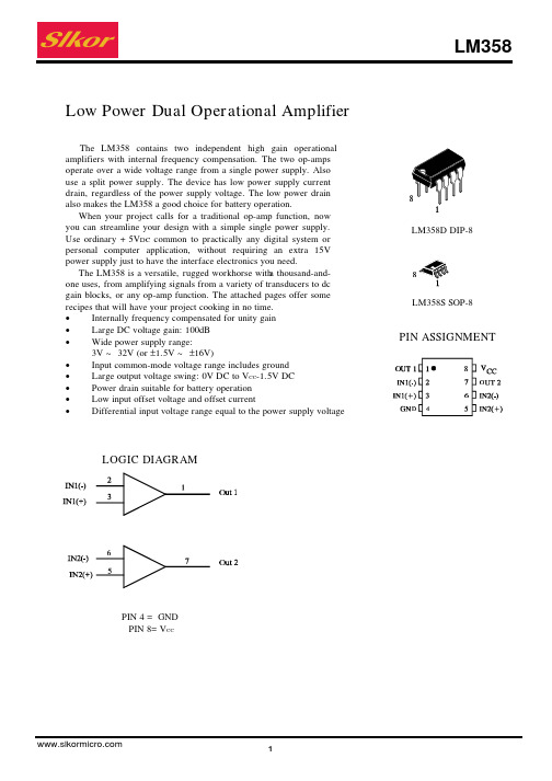
operate over a wide voltage range from a single power supply. Also
use a split power supply. The device has low power supply current
drain, regardless of the power supply voltage. The low power drain
• Low input offset voltage and offset current
• Differential input voltage range equal to the power supply voltage
LOGIC DIAGRAM
LM358D DIP-8
LM358S SOP-8
3
TYPICAL PERFORMANCE CHARACTERISTICS
LM358
Figure 1.Input Voltage Range
Figure 2. Open-Loop Frequency
Figure 3. Large-Signal Frequency Response
Figure 4. Small-Signal Voltage Follower Pulse Response (Noninverting)
Differential Input Voltage Range
Test Conditions VO=1.4V VCC=5.030V;RS=0Ω VICM=0V to VCC-1.7V RS=0Ω, VCC=30V
VCC=5.0V
RS=0Ω, VCC=30V
VCC=5.0V
VCC=30V
Transcend StoreJet 35Ultra 说明书
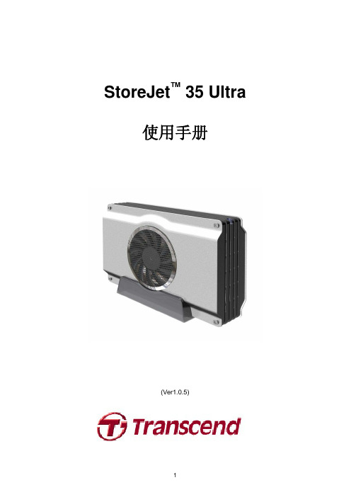
StoreJet™ 35 Ultra使用手册(Ver1.0.5)目录产品介绍︱ (3)包装内容︱ (3)产品特色︱ (4)系统需求︱ (4)安全注意事项︱ (5)一般使用 (5)设定 (5)资料备份 (5)电源 (5)提醒您 (5)产品概观︱ (6)安装硬盘︱ (7)将StoreJet 35 Ultra连接到计算机︱ (9)Windows®2000/XP (9)Windows Vista™ (10)Mac® OS (11)Linux® (11)安全删除StoreJet 35 Ultra︱ (12)Windows® 2000, XP and VISTA™ (USB) (12)Windows® 2000, XP and VISTA™ (eSATA) (12)Mac® OS (USB & eSATA) (14)Linux® Kernel 2.4或更新版本 (USB) (14)格式化硬盘︱ (15)Windows®2000/XP (15)Windows Vista™ (16)Mac® OS (18)Linux® (20)疑难排解︱ (21)疑难排解︱ (21)产品规格︱ (23)订购信息︱ (23)质保条款︱ (24)产品介绍︱感谢您购买创见StoreJet™ 35 Ultra硬盘外接盒。
本产品支持eSATA/USB2.0双接口规格,USB接口兼容于大多数的台式或笔记型计算机,eSATA接口则可提供每秒高达3.0Gb的传输速率,让硬盘效能达到极致。
此外,StoreJet 35 Ultra更配备超静音80mm 风扇,可有效降低硬盘过热的风险;本产品还附赠实用的备份软件,可进一步协助使用者提升工作效率*。
加装硬盘后,StoreJet 35 Ultra即成为绝佳的数据管理储存装置,可用来下载、储存、传输并备份宝贵的档案与数据。
2-IN, 1-OUT CAT-5自动切换器用户指南说明书

MANUAL PART NUMBER: 400-0378-001SW1956CT2–IN, 1–OUT CAT-5 AUTO-SWITCHERUSER’S GUIDETABLE OF CONTENTSPagePRECAUTIONS / SAFETY WARNINGS (2)GENERAL (2)INSTALLATION (2)CLEANING (2)FCC/CE NOTICE (2)ABOUT YOUR SWITCHER (3)TECHNICAL SPECIFICATIONS (3)DESCRIPTION OF SW1956CT (4)APPLICATION DIAGRAM (5)DIAGRAM1:TYPICAL CONNECTION (5)DIAGRAM2:INTERNAL VIEW (6)INSTALLING YOUR SWITCHER (7)OPERATION (7)TROUBLESHOOTING GUIDE (8)THE POWER LED IS OFF (8)UNIT DOES NOT AUTO-SWITCH (8)NO DISPLAY (8)ALTINEX POLICY (9)LIMITED WARRANTY/RETURN POLICY (9)CONTACT INFORMATION (9)121Please read this manual carefully before using your SW1956CT Switcher. Keep this manual handy for future reference. These safety instructions are to ensure the long life of your SW1956CT and to prevent fire and shock hazard. Please read them carefully and heed all warnings. 1.1 GENERAL• Qualified ALTINEX service personnel, or theirauthorized representatives must perform all service. 1.3 INSTALLATION• For best results, place the SW1956CT on a flat,level surface. Keep in a dry area away from dust and moisture. • To prevent fire or shock, do not expose this unitto rain or moisture. Do not place the SW1956CT in direct sunlight, near heaters or heat radiating appliances, or near any liquid. Exposure to direct sunlight, smoke, or steam can harm internal components. • Handle the SW1956CT carefully. Dropping orjarring can damage internal components. • Do not place heavy objects on top of theSW1956CT . If the unit is to be mounted to a table or wall, use only Altinex made mounting accessories. • To turn off the main power, be sure to removethe cord from the power outlet. The power outlet socket should be installed as close to the equipment as possible, and should be easily accessible. • Do not pull the power cord or any cable that isattached to the SW1956CT Switcher. • If the SW1956CT is not used for an extendedtime, disconnect power cord from the outlet.1.4 CLEANING• Unplug the SW1956CT power cord beforecleaning. Clean surfaces with a dry cloth. Never use strong detergents or solvents, such as alcohol or thinner. Do not use a wet cloth or water to clean the unit. 1.5 FCC / CE NOTICE• This device complies with Part 15 of FCC Rules.Operation is subject to the following two conditions: (1) This device may not cause harmful interference, and (2) this device must accept any interference, including interference that may cause undesired operation. • This equipment has been tested and found tocomply with the limits for a Class A digital device, pursuant to Part 15 of FCC Rules. These limits are designed to provide reasonable protection against harmful interference when equipment is operated in a commercial environment. This equipment generates and uses radio frequency energy. If not installed and used in accordance with the instruction manual, it may cause harmful interference to radio communications. Operation of this equipment in a residential area is likely to cause harmful interference in which case the user will be required to correct the interference at his own expense. • Any changes or modifications to the unit notexpressly approved by Altinex, Inc. could void the user’s authority to operate the equipment.32SW1956CT2-In, 1 Out CAT-5 Auto-SwitcherThe SW1956CT is a 2-In, 1-Out CAT-5 Auto-Switcher. The SW1956CT automatically switches on signal detection, but may also be controlled manually if desired. The SW1956CT is designed to switch Altinex CAT-5/6 Twisted Pair Transmitter and Receiver signals. These include Altinex part numbers DA1920SX , DA1921SX , DA1930CT , DA1931CT , MT103-115 and MT103-116.The unit is encased in a solid metal enclosure and ships with an external, 9V 500mA, power adapter. Also included is an external contact-closure switch for manual override of input selection.Manual override switching is made via a contact closure on the INPUT SELECT jack. This switch may be used for manual control, or the contact closure may be controlled from a control system. The SW1956CT is perfect for applications that use wall or floor plates for auto switching. The SW1956CT may be mounted to furniture or other suitable surfaces using optional hardware.3FEATURES/DESCRIPTI ON SW1956CT InputsTwoInput Connector RJ-45 FemaleOutputsOneOutput Connector RJ-45 FemaleCompatibilityAudio + VGA thru UXGATable 1. SW1956CT GeneralMECHANICAL SW1956CT Material 0.1” Al Finish Gray Height (inches) 3.00in (76mm) Width (inches) 4.38in (111mm) Depth (inches) 1.00in (25mm) Weight (pounds) 0.4lbs (0.18kg) Ship Weight (pounds) 2.0lbs (0.91kg) T ° Operating 10°C-35°C T ° Maximum 50°C Humidity 90% non-condensing MTBF (calculations) 40,000 hrs (min.) Table 2. SW1956CT MechanicalELECTRICAL SW1956CT Input Signal Analog Signal 1.0V p-p max Output Video Signals Analog Signal 1.0V p-p max Frequency CompatibilityHorizontal 15-200 kHz Vertical 20-190 Hz Typical Video Bandwidth 350 MHz @ -3dB Cross-talk -40dB @10 MHzCoupling DC Power External Power Adapter 9V 500mA (included) Power Consumption 3 watts max. Table 3. SW1956CT Electrical45DIAGRAM 1 : TYPICAL CONNECTIONAltinex provides a remote control switch with a 6 foot cable, Altinex part number RC5203CC, which will control the SW1956CT manually.When the remote control switch is connected to the INPUT SELECT jack, INPUT 1 will be selected if the channel select contact is closed. INPUT 2 will be selected if the channel select contact is open.The switching will be identical whether there are one or two active signals. The indicator lights located next to the input ports indicate which input is selected.5DIAGRAM 2 : INTERNAL VIEW676Step 1. Make sure that the correct power adapteris used. The Altinex power adapter is supplied with the unit. Step 2. Connect the power adapter to the powerport.CAUTION: The POWER port and the INPUT SELECT port use the same connector type. Make sure the power adapter is connected to the POWER port.Step 3. The POWER indicator light and theINPUT 2 indicator light should turn ON. Step 4. Connect the SW1956CT inputs to theoutputs of the DA1930CT VGA+AUDIO to CAT-5/6 Transmitters. Step 5. Connect a cable from the output port ofthe SW1956CT to the input port of the DA1931CT CAT-5/6 to VGA+AUDIO Receiver. Step 6. If the remote control switch is to be used,connect the RC5203CC to the INPUT SELECT port.CAUTION: The POWER port and the INPUT SELECT port use the same connector type. Make sure the control switch is connected to the INPUT SELECT port.Step 7. Verify that the picture quality on thedisplay is good. If a signal is not being received, make sure that the display is compatible with the resolution of the computer graphics card.There are no settings to adjust on the SW1956CT Auto-Switcher. The SW1956CT will operate successfully as long as cables are attached properly and other technical specifications are followed.AUTO-SWITCH MODEThe SW1956CT automatically selects the INPUT 2 port if there are no active signals present. If there is an active signal on INPUT 2 and not on INPUT 1, then the SW1956CT will maintain INPUT 2 as the active port. However, when an active signal is applied to INPUT 1, the SW1956CT will switch to INPUT 1.If there are active signals on INPUT 1 and INPUT 2, the SW1956CT will automatically switch to INPUT 1.MANUAL SWITCH MODEManual override is accomplished via a contact closure on the INPUT SELECT jack. Manual Switch Mode disables Auto-Switching.Included with the SW1956CT is an external manual switch with a six foot cable, Altinex part number RC5203CC . This switch may be used for manual control, or the contact closure may be made from a control system. This port uses a 2.5mm mini-coaxial remote control jack and it is located next to the CAT-5 OUTPUT.INPUT 1 will be selected when the remote control switch is connected to the INPUT SELECT jack and the contact is closed. INPUT 2 will be selected if the contact is open.CAUTION: The connector used for the INPUT SELECT port is the same type as is used for the POWER connector. Use caution to ensure the switch is connected to the correct port.88We have carefully tested and have found no problems in the supplied SW1956CT unit. However, we would like to offer the following suggestions:8.1 THE POWER LED IS OFFCause 1: The power adapter is installedwrong. Solution 1: Make sure the adapter output isconnected to the POWER input jack on the unit. Check the unit carefully. The POWER input jack and the INPUT SELECT jack are the same type. If the POWER LED is still not on, see Solution 2. Solution 2: Make sure the adapter is pluggedinto a proper AC outlet that has power. If the adapter has AC power and the POWER LED is still off, see Cause 2. Cause 2: The wrong power adapter isinstalled. Solution 1: Please use the Altinex suppliedexternal adapter (9V, 500mA). If the POWER LED is still not on, please call ALTINEX at (714) 990-2300. 8.2 UNIT DOES NOT AUTO-SWITCHCause 1: The manual override switch isinstalled. Solution: Remove the connection to theINPUT SELECT jack on the unit. If a plug is installed in the jack, even without a switch, the unit will not auto-switch properly. If the unit does not auto-switch with the plug removed, see Cause 2. Cause 2: The signal is not active or isimproperly formatted. Solution 1: Remove the input signals from theswitcher. If the IN 2 LED is OFF, call ALTINEX at (714) 990-2300. If the IN 2 LED is ON, see Solution 2. Solution 2: Connect a properly formatted signalfrom an Altinex CAT-5/6 Transmitter to INPUT 1. If the switcher does not switch to INPUT 1, see Solution 3. Solution 3: Bypass the switcher and connect theoutput of the transmitter directly to the input of the receiver. If the display is good, then call ALTINEX at (714) 990-2300. 8.3 NO DISPLAYCause 1: The source has a problem. Solution: Check the source and make surethat there is a signal present and all source connections are correct. If the source is working and there is still no display, see Cause 2. Cause 2: Manual override is ON.Solution: Make sure there is nothingconnected to the INPUT SELECT port on the switcher. If there is nothing connected, see Cause 3. Cause 3: Signal is bad or missing.Solution 1: Make sure the switcher output isconnected to the CAT-5/6 Receiver input and the receiver is ON. If there is still no display, see Solution 2. Solution 2: Remove both inputs to the switcherand connect the active signal form the CAT-5/6 Transmitter output to INPUT 2. If there is still no display, see Solution 3. Solution 3: Bypass the switcher and connect theoutput of the transmitter directly to the input of the receiver. If the display is good, then call ALTINEX at (714) 990-2300. If there is still no display, see Cause 4.9Cause 4: Cable connections are incorrect. Solution: Make sure that cables are properlyconnected. Also, make sure that the continuity and wiring are good. If there is still no display present, see Cause 5. Cause 5: The display has a problem.Solution: Make sure the display has powerand is turned ON. If there is still no display, please call Altinex at (714) 990-2300.99.1 LIMITED WARRANTY/RETURN POLICYPlease see the Altinex website at for details on warranty and return policy.9.2 CONTACT INFORMATION ALTINEX, INC 592 Apollo street Brea, CA 92821 USA TEL: 714 990-2300TOLL FREE: 1-800-ALTINEX WEB: E-MAIL: *********************。
ISA-358GE(F)备用电源自动投入装置技术使用说明书V3.21-120901
ISA-358GE(F)备用电源自动投入装置技术使用说明书Ver 3.21编写:叶志锋蔚凡杜东威审核:远生许永军批准:徐成斌长园深瑞继保自动化二〇一一年三月本说明书由长园深瑞继保自动化编写并发布,并具有对相关产品的最终解释权。
相关产品的后续升级可能会和本说明书有少许出入,说明书的升级也可能无法及时告知阁下,对此我们表示抱歉!请注意实际产品与本说明书描述的不符之处。
更多产品信息,请访问互联网:.sznari.技术支持:(0755) 3301-8668/8647/8610传真:(0755) 3301-8889/8664欢迎拨打免费客户服务:400-678-8099目录1装置概述 (1)1.1基本配置 (1)1.2主要性能特点 (2)2技术参数 (3)2.1环境参数 (3)2.2额定电气参数 (3)2.3主要技术指标 (3)2.4通讯接口 (4)2.5抗干扰性能 (4)3备自投一般性说明 (5)3.1备自投基本原则 (5)3.2备自投基本逻辑 (5)4备自投典型逻辑 (8)4.1分段备自投(FBZT) (8)4.2变压器备自投(BBZT) (9)4.3进线备自投(LBZT) (11)5保护和告警功能 (13)5.1母线TV断线告警 (13)5.2进线TV断线告警 (13)5.3全所无压告警 (13)5.4闭锁备自投告警 (14)5.5断路器拒动告警 (14)5.6分段断路器过流保护 (14)5.7分段断路器零序保护 (15)5.8进线断路器过流保护 (15)5.9进线断路器零序保护 (16)5.10过负荷联切 (17)5.11母线接地告警 (17)6辅助功能 (19)6.1信号系统 (19)6.2事故分析与过程记录 (19)7保护配置及整定说明 (25)7.1装置元件配置 (25)7.2装置定值 (26)7.3出口配置 (34)8装置动作事件类型定义 (34)9装置背板布置及端子接线 (37)9.1分段备自投元件 (37)9.2断路器保护、过负荷联切 (38)9.3变压器备自投元件 (39)9.4进线备自投元件 (39)9.5装置其它端子接线 (40)10装置订货说明 (41)10.1基本订货参数 (41)10.2装置命名规则 (41)10.3装置型号列表 (41)附录A装置使用说明 (42)A.1面板布置与显示 (42)A.2菜单界面操作说明 (43)A.3查看录波记录 (48)A.4装置通讯功能说明 (50)A.5装置打印功能 (53)附录B装置调试与投运说明 (56)B.1调试资料准备 (56)B.2通电前检查 (56)B.3上电检查 (56)B.4整机调试 (56)B.5装置投入运行操作步骤 (57)B.6装置运行说明 (58)B.7注意事项 (58)【附图1】ISA-358GE分段和进线备自投原理接线图 (60)【附图2】ISA-358GF分段和变压器备自投原理接线图 (61)【附图3】ISA-358GE/F测控原理接线图 (62)【附图4】ISA-358GE/F装置端子排接线图 (63)【附图5】ISA-358GE/F装置前视后视图 (64)【附图6】ISA-358G装置操作板(WB741B)原理接线图 (65)1装置概述ISA-358G备用电源自动投入装置,用于实现110kV及以下电压等级、不同接线方式变电站的备用电源自动投入功能。
- 1、下载文档前请自行甄别文档内容的完整性,平台不提供额外的编辑、内容补充、找答案等附加服务。
- 2、"仅部分预览"的文档,不可在线预览部分如存在完整性等问题,可反馈申请退款(可完整预览的文档不适用该条件!)。
- 3、如文档侵犯您的权益,请联系客服反馈,我们会尽快为您处理(人工客服工作时间:9:00-18:30)。
接线端子板TB358-RTD
1基本说明
TB358-RTD端子板是16路热电阻信号输入端子板,可供两块不冗余的FW358卡作为热电阻信号输入卡时使用。
可测量16路三线制热电阻(Pt100或Cu50)信号。
2使用说明
2.1端子板外观图
TB358-RTD端子板结构外形如图 2-1 所示:
图 2-1 TB358-RTD端子板结构外形图
2.2接插件说明
表 2-1 TB358-RTD端子板接插件说明
标号说明
J1 接线端子
J2 第一块卡数据连线插座
J3 第二块卡数据连线插座
2.3三线制信号输入方式说明
若热电阻信号为三线制输入方式,以A、B、C表示三线的热电阻接到端子板上的接线标号,
假如我们把一个热电阻Rt 接到FW358卡的第一通道上,那么接线端子1接A 、端子2接B 、端子3接C ,如图2-2所示。
图 2-2三线制输入方式接线
2.4 端子定义及接线
TB358-RTD 接线端子说明如表 2-2所示:
表 2-2接线端子说明
描述 端子号 描述 CH 1A 1 2 CH 1B CH 1C 3 4 CH 2A CH 2B 5 6 CH 2C
CH 3A 7 8 CH 3B CH 3C
9 10CH 4A CH 4B 1112CH 4C CH 5A 1314CH 5B CH 5C 1516CH 6A CH 6B 1718CH 6C CH 7A 1920CH 7B CH 7C 2122CH 8A 一号卡
CH 8B
2324CH 8C CH 9A 2526CH 9B CH 9C 2728CH 10A CH 10B 2930CH 10C CH 11A 3132CH 11B CH 11C 3334CH 12A CH 12B 3536CH 12C CH 13A 3738CH 13B 二号卡
CH 13C
39
40
CH 14A
CH 14B 4142CH 14C CH 15A 4344CH 15B CH 15C 4546CH 16A CH 16B 4748CH 16C 保护地端子4950保护地端子
z端子号为1~24的接线端子连接第一块卡的信号线;端子号为25~48的接线端子连接第二块卡的信号线。
z“CH1A”表示第1路信号输出A端,“CH1B”表示第1路信号输出B端,“CH1C”表示第1路信号输出C端,数字表示通道号,依次类推。
z该端子板无须供电。
3资料版本说明
表 3-1版本升级更改一览表
资料版本号输出时间更改说明TB358-RTD使用手册(V1.0)。
