HART指令-ROSEMOUNT流量计实现HART通信
ROSEMOUNT 3051变送器HART375树形菜单中英文对照
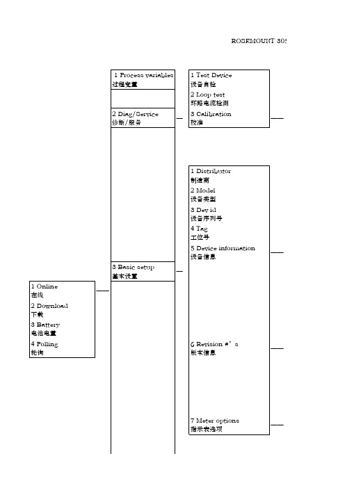
1 flange type 法兰类型 2 flange material 法兰材料 3 oring material O型圈材料 4 drain vent matl 排气排液阀 5 remote seal type 远传装置形式 6 seal fill fluid 远传装置灌充液 7 rmt seal isol matl 远传装置隔离膜片 8 num of rmt seals 远传装置数量
4 Polling 轮询
3 Basic setup 基本设置
——
1 Distributor 制造商 2 Model 设备类型 3 Dev id 设备序列号 4 Tag 工位号 5 Device information 设备信息
—
——
6 Revision #’s 版本信息
——
7 Meter options 指示表选项
——
1 Sensor 传感器
——
4 Detailed setup 详细设置
—
2 Signal condition 信息状况
——
3 Field device info 材料信息
——
4 Sensor information 传感器信息
——
OUNT 3051树形菜单
1 Apply value 上下限调试 2 D/A trim D/A 校准 3 Sensor trim 传感器校准 4 Recall factory trim 恢复制造商校准
1 Meter type 指示表类型
2 CM Setup 远程显示设置
HART手操器使用说明
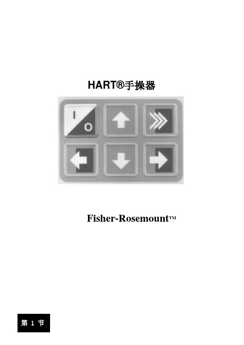
HART®手操器Fisher-Rosemount TM 1HART®手操器概述HART(Highway Addressable Remote Transducer高速可寻址遥远的转换器)手操器(图1-1)是手持式设备,提供了联接到所有的HART-相容基于微处理的仪器设备的通用通讯。
第 1 节讨论 HART 手操器的连结,液晶显示, 键盘,脱机和联机菜单、电池组、存储模块和数据包装 100 ,维护和 2000 年问题兼容性。
也包括一些手操器的功能性方面的简短概述。
第 2 节描述对 Fisher- Rosemount 的 HART 的通常任务设置和通用屏幕显示设置。
第 3 节显示Fisher-Rosemount 产品典型的设置菜单树。
HART 手操器可以与任何 HART-相容的设备在 4 – 20 mA 回路的任何点接入,在手操器和电源之间必须提供了最小负载为250欧姆电阻。
HART 手操器使用 Bell 202 移频键(FSK) 高频数传讯号的技术叠加在标准的 4 – 20 mA 电流传送回路。
因为加在回路上总的高频信号电压为零 ,所以手操器与通讯设备之间的信号不会通信干扰 4 – 20 mA 讯号。
液晶显示(LCD)功能键动作键字母键Shift 键图 1-1. HART 手操器1-1HATR手操器的连接HATR手操器可以通过后部的连接面板(如图 1-2)在控制室、设备安装点或者在回路的任何连接点与变送器通讯。
为了通讯,通过合适的连接器并联仪表或负载电阻连接HATR手操器,所有的连接必须是非极性的。
当连接到计算机时,必须通过计算机通讯适配器连接到手操器的串口。
回路连接1 / 39HART 手操器说明串口回可换镍镉钮扣电池1-2注意:为了HATR手操器正确执行功能,在回路中必须有最小为250欧姆的电阻值。
HART手操器不能直接测量回路电流。
图1-3和图1-4例举了HART手操器与任何兼容设备之间的典型接线图图1-3 连接到变送器的接线端子2 / 39图1-4 手操器连接到回路中图1-5显示如何连接可选的250欧姆负载电阻器(Load Resistor)注意:安装临时的250欧姆负载电阻器1.将负载电阻器插入安装插孔2.断开回路将电阻器串接入回路3.闭合回路图1-5 带负载电阻器的手操器连接液晶屏(LCD)LCD屏为连接设备之间提高了8行21个字符的通讯。
HART协议简介及在智能电磁流量计中的应用

HART协议简介及在智能电磁流量计中的应用
1.引言HART,即Highway Addressable Remote Transducer,是可寻址远程传感器高速公路的简称,最早由美国Rosemount 公司开发并得到八十多家
著名仪表公司的支持,其特点是在不干扰4~20mA 模拟信号的同时允许双向数
字通讯。
符合HART 协议的智能电磁流量计不仅可以实现各种流量的检测和就地显示,还可以通过上位计进行远程设定,改变流量计的零点、量程,以及完成自诊断
等功能,在很大程度上方便了流量计的使用和维护,因而具有较强的市场竞争
力。
[1]本文讨论基于HART 协议智能电磁流量计具体实现的技术问题,一是要
解决硬件电路的设计问题,二是要讨论实现HART 协议命令集编程及上位机软
件的实现。
2 HART 协议简介
HART 协议遵循ISO 制订的OSI 开放式系统互连参考模型,采用了OSI
模型的第一层、第二层和第七层,即物理层、数据链路层和应用层。
2.1 物理层规范
HART 协议采用美国电话通讯系统Bell202 频移键控(FSK)标准,在4~20mA 的模拟±0.5mA 的正弦波,波特率是1200bps。
因为所叠加的正弦信号平均值为0,而且相位连续频移键控技术要求在波特率为1200Hz 的
数据位 1 和0 的边界的相位角是连续的,所以数字通讯信号不会影响
4~20mA 的模拟信号。
2.2 数据链路层规范[2][3]
这一部分协议规定了HART 帧的格式,实现建立、维护、数据链路通
讯功能,HART 协议根据冗余检错码信息,通过差错检测机制和采用自动重发。
(完整word版)罗斯蒙特质量流量计操作说明
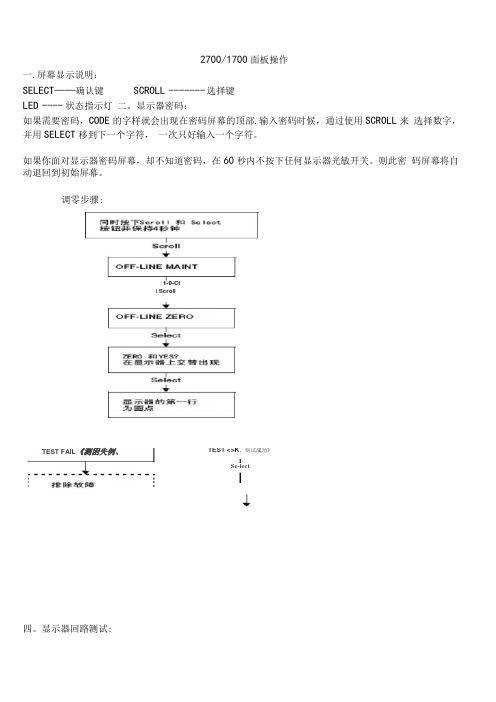
2700/1700面板操作一.屏幕显示说明:SELECT——确认键SCROLL ------- 选择键LED ---- 状态指示灯二。
显示器密码:如果需要密码,CODE的字样就会出现在密码屏幕的顶部.输入密码时候,通过使用SCROLL来选择数字,并用SELECT移到下一个字符,一次只好输入一个字符。
如果你面对显示器密码屏幕,却不知道密码,在60秒内不按下任何显示器光敏开关。
则此密码屏幕将自动退回到初始屏幕。
调零步骤:四。
显示器回路测试:TEST <>K。
则试成功》ISe-lectI1-0-CtI ScrollTEST FAIL《测困失例、五. Set MA01Set MA024 mA12 mA20 mASe eelScroll3e eel正码?二>SelectScrollOFF-LINE SIMSelectScrollScroll1 KMzIDKHzSclent读取接受设餐的输出HPYesSst D01Set D02SelectScrollOHOFP阱I M]读取接克设备的箍出致T回路测试成功女%,人出?狂.停止历具ScrollExh检登回率接线排除输出故慎显示器查看报警:LED指示灯状态及报警查看状态指示灯的状态报警优先级魄色无报警-正常运行模式鼻电闪姆”已改正但尚未信认的状态黄色已偏认的低强度报警黄色闪探⑴未稳认的做强度报警虹笆己碉认的高强度指警红色闪峭'未询认的高强虚报警11)如果报警菜单被禁止,则无沫箱认报警,在这种情况下.状态指示LEim不再闪保工报警按照报警队列中的优先级排列,要查看队列中某指定报警:L同时按下配Ml和Select按钮,当屏幕上出现"EE ALARM'」札松开按钮“ 参阅图7-1.2 .按Select按钮,3 .如果屏幕上交替出现“AGK ALL”时,则按配FQ11按钮,4 .如果屏幕上出现"0 ALARN” ,则到第6步,5,按配ell按钮查看队列中的每个技警.要了解显示帚显示的报警代码的含义请参阅翦1QJ1幸节,6,按Scroll按钮直到解幕上出现“EXIT” ”7.按Select按祗六.管理累积量和库存量:(完整word 版)罗斯蒙特质量流量计操作说明宫动/停止所有累租值和质存量⑵进行酬重副可定翻值出现空位七:测量单位设置:SELECT+SCROLL 按 4 秒 ----- ► SEE ALARM ---- ► [SCROLL] ---- ►OFFLINE MAINTAIN -------- ► [SELECT]- ..... > [SCROLL] ----- ►CONFIG ----- ► [SELECT] ---- ► MASS ------- [SELECT] ------- ►SELECTI 如果有需求.输入密码SELECTSELECT如果有需求,输入密码SELECTSELECT复位!特定累积值⑴深部翻屏直到特定累积值可以按SCROLL选择你要的单位> 选定后按SELECT按SCROLL 直到出现EXIT ----- ► [SELECT]体积单位和密度单位设置和上述步骤相同八量程设置(LRV URV)[SELECT+SCROLL] 按 4 矛秒/ SEE ALARM ------- ► [SCROLL] --- ►OFFLINE MAINTAIN --------- ► [SELECT^ ------ ►继续按SCROLL 直到出现MAO1[SELECT] ----------------------------- k SRC MAO1 ------ k [SELECT]MFLOW ---- ► [SELECT]----- SRC MAO1 ——[SCROLL]4 MAO1 ----- ►输入最小量程------ ►[SCROL L+SELEC T] 4 MAO1 ------- ► [SCROLL] ------ ►——20HMAO1 ----------- ►[SELECT] 输入最大量程------ ►[SELECT+SCROLL]--------------- > 20 MAO1>[SCROLL]EXIT ---- ^ 按SELECT 退出.其他量程设置和上述步骤相同。
罗斯蒙特质量流量计说明及操作规范,罗斯蒙特质量流量计中国总代理
罗斯蒙特质量流量计中国总代理(网址:),德莱美(北京)国际贸易有限公司中国总代理(网址:)罗斯蒙特质量流量计工作特性及原理,罗斯蒙特质量流量计中国总代理,罗斯蒙特质量流量计广泛应用于石化等领域,是当今世界上最先进的流量测量仪表之一,在我厂主要产品如乙烯、丙烯和主要原料轻烃等的测量中使用可靠,精度高达1.7‰,为我厂的能源、物料的流量测量提高了准确度,避免了不必要的损失,创造了可观的经济效益。
质量流量测量原理一台质量流量计的计量系统包括一台传感器和一台用于信号处理的变送器。
Rosemount质量流量计依据牛顿第二定律:力=质量×加速度(F=ma)如图1所示,当质量为m的质点以速度V在对P轴作角速度ω旋转的管道内移动时,质点受两个分量的加速度及其力:(1)法向加速度,即向心加速度αr,其量值等于2ωr,朝向P轴;(2)切向角速度αt,即科里奥利加速度,其值等于2ωV,方向与αr垂直。
由于复合运动,在质点的αt方向上作用着科里奥利力Fc=2ωVm,管道对质点作用着一个反向力-Fc=-2ωVm。
当密度为ρ的流体在旋转管道中以恒定速度V流动时,任何一段长度Δx的管道将受到一个切向科里奥利力ΔFc:ΔFc=2ωVρAΔx (1)式中,A—管道的流通截面积。
由于存在关系式:mq=ρV A所以:ΔFc =2ωqmΔx (2)因此,直接或间接测量在旋转管中流动流体的科里奥利力就可以测得质量流量。
传感器内是U型流量管(图2),在没有流体流经流量管时,流量管由安装在流量管端部的电磁驱动线圈驱动,其振幅小于1mm,频率约为80Hz,流体流入流量管时被强制接受流量管的上下垂直运动。
在流量管向上振动的半个周期内,流体反抗管子向上运动而对流量管施加一个向下的力;反之,流出流量管的流体对流量管施加一个向上的力以反抗管子向下运动而使其垂直动量减少。
这便导致流量管产生扭曲,在振动的另外半个周期,流量管向下振动,扭曲方向则相反,这一扭曲现象被称之为科里奥利(Coriolis)现象,即科氏力。
Hart_Protocol

HART 协议1.HART 协议概况HART 协议是美国Rosemount 公司于1986年提出的一项标准通讯协议,其全称为Highway Addressable Remote Transducer,即可寻址远程传感器数据公路。
就现场总线的意义上说,HART 协议的特点是具有与现场总线类似的体系结构,具有总线式的数字通讯,但HART 并不是真正的现场总线,它只是现场总线的雏形,是从模拟控制系统向现场总线过渡的一块踏脚石。
所谓“过渡”,是指它在4~20mA模拟信号上叠加FSK(Frequency Shift Keying,频移键控,详见第二节)数字信号,既可进行4~20mA 模拟信号的传输,又能进行数字通讯,同时,数字通讯信号不影响模拟信号的传输。
显然,这是一项4~20mA模拟信号与数字通讯相兼容的标准。
作为一个开放性协议,经过十多年的发展,HART 协议已成为智能仪表事实上的工业标准。
HART 通讯协议参照“ISO/OSI”的模型标准,简化并引用其中的1,2,7三层制定而成,即:物理层,数据链路层和应用层,对应关系如下:2.HART 协议的物理层本节主要描述了HART 协议的物理层的信号模式和传输介质等,这些都是与OSI 协议参考模型的物理层的规定相一致的。
(1)FSK 频移键控HART 协议采用了Bell202 标准的FSK 频移键控信号。
它在4~20mA的模拟信号上叠加幅度为0.5mA的正弦调制波,1200Hz 代表逻辑“1”,2200Hz代表逻辑“0”,如下图所示。
由于所叠加的正弦信号平均值为0,所以不会影响4-20mA的输出电流。
因此,模拟仪表在数字通讯时仍可以照常工作,这是HART标准的重要优点之一。
二进制数据传送的速率为1200波特。
这就意味着“1”由1200Hz 的一个周期表示,而“0”大约由2200Hz 的两个周期表示。
信号频率和传送速率的选择依据美国Bell202标准,该标准用于在电话网上传送数字信息。
hart,协议,变量
竭诚为您提供优质文档/双击可除hart,协议,变量篇一:haRt协议简介haRt协议是由Rosemount(罗斯蒙特)公司提出的一种用于现场智能仪表和控制室设备之间的通信协议,它是4~20ma模拟信号向全数字信号过渡的一种协议,在4~20ma标准的模拟信号上叠加一个数字信号,原模拟信号仍然有效,且数字信号和模拟信号互不影响。
haRt协议的有线部分参照了iso的osi七层模型中的标准物理层、数据链路层和应用层这三层。
haRt协议有线部分的物理层规定了信号的传输方法和传输媒介,它采用基于bell202标准的频移键控技术(Fsk)来把数字信号叠加到4~20ma电流回路中。
它用1200hz的正弦波代表逻辑1,用2200hz的正弦波代表逻辑0,电流峰峰值为正负0.5ma。
如下图所示:+0.5ma0ma–0.5maa啊haRt协议有线部分的数据链路层规定了haRt有线协议帧的格式。
请求帧和响应帧格式如下所示:图1haRt帧格式haRt协议的应用层包括三个类别的haRt命令,用haRt 命令来操作数据,包括通用命令、常用命令和特殊命令,目前最新版本haRt协议的各类命令的命令号范围如下表所示:文章转载自沈阳中科博微自动化技术有限公司工业通讯大课堂篇二:haRt协议简介haRt转Rs-232串行口适配器haRt协议简介现代工业生产中存在着多种不同的主机和现场设备,要想很好地使用他们,完善的通讯协议是必须的。
haRt协议最初是由美国Rosemount公司开发,已应用了多年。
haRt协议使用Fsk技术,在4~20ma信号过程量上叠加一个频率信号,成功地把模拟信号和数字信号双向同时通讯,而不互相干扰。
haRt协议参照了国际标准化组织的开放性互连模型,使用osi标准的物理层、数据链路层、应用层。
haRt协议规定了传输的物理形式、消息结构、数据格式和一系列操作命令,是一种主从协议。
当通讯模式为“问答式”的时候,一个现场设备只做出被要求的应答。
hart总线

图2 HART 协议通信的FSK 信号
2.2数据链路层
定义了一项主从协议 - 在正常使用下,现场设备只在收 到信号时才作回答。可以有两个主设备,例如,控制系统 作为第一主设备,而手持HART通信器作为第二主设备。时 序规则定义每个主设备可以开始通信事务的时间。单个多 点线缆对可以连接多达15个或更多的从设备。
协议物理层 数据链路层 网络层 传输层 应用层
2.1协议物理层
物理层:HART协议的物理层规定了信号的传输方法、传输介质,HAR T支持模拟信号和数字信号在同一线路上传输。以贝尔202标准为基 础,采用频移键控(FSK),以1200bps的速率通信。代表0和1位值 的信号频率分别为2200和1200Hz。该低电平信号叠加在4到20mA的模 拟测量信号之上,而不会对模拟信号造成任何干扰。
HART总线
主讲人:梁 赵 易
HART总线
1.简介
2.HART规范 3.操作命令 4.工作方式 5.通信优势
1.简介
HART(Highway Addressable Remote Transduc er),可寻址远程传感器高速通道的开放通信 协议,是美国ROSEMOUNT公司于1985年推出的 一种用于现场智能仪表和控制室设备之间的通 信协议。 HART装置提供具有相对低的带宽, 适度响应时间的通信,经过10多年的发展,HA RT技术在国外已经十分成熟,并已成为全球智 能仪表的工业标准。
3.2常用重要命令
(1)0号和11号命令用于识别现场设备。我们知道无论 采用长结构还是短结构都可以标识现场设备,应答0号命 令的信息中就包含了对不同设备的标识;然后,主机建 立不同的标志,为随后的长结构命令做准备。在HART4.0 版本及以前,传输类型码分为2字节:一个是生产厂商代 码,另一个是设备类型代码。而两个字节还可以节略。 到了HART5.0版本就必须使用充扩的代码表示设备信息, 还用ID号代替了最终流水线号。一个主机通常以0号命令 开始通讯,赋予随选地址0,然后扫描1~15地址,看谁 期待操作,显然由于HART5.0版本后的设备,主机可以使 用11号命令,再带一个全0的广播地址,外加命令中的标 志作为数据,等待着具有相同标志的从机响应,而应答 的11号命令等同于0号命令。
Emerson Rosemount 2051 压力变送器产品说明书
产品数据表00813-0106-4101, Rev R C2022年4月Rosemount™ 2051 压力变送器■Rosemount™ Coplanar™共平面平台可实现一次元件、阀组与分体式密封解决方案的集成■性能出色,精度高达 0.05%■IEC 62591 (Wireless HART®) 实现经济高效安装■本地操作界面 (LOI) 为变送器提供易用的组态功能■可用协议包括 4–20 mA HART®、F OUNDATION™现场总线、PROFIBUS® PA 和 HART 1–5 Vdc 低功率■可选择的 HART 版本让您的工厂拥有最新的 HART 功能,同时确保与当前系统无缝集成■整个 4-20 mA HART 产品系列通过了 IEC 61508 SIL2/3 级安全认证,简化了法规遵从性2051 型压力变送器2022年4月内容Rosemount 2051 压力变送器产品系列 (2)Rosemount 2051C 共平面压力变送器订购信息 (4)Rosemount 2051T 直连式压力变送器订购信息 (15)Rosemount 2051G 直连式压力变送器订购信息 (24)Rosemount™ 2051CF 流量计 (31)Rosemount 2051L 液位变送器 (62)技术规格 (72)产品认证 (88)尺寸图 (110)选项 (125)Rosemount 2051压力变送器产品系列可靠测量的基础■差压、表压和绝压测量■齐全的差压流量计、液位变送器、阀组及法兰产品线■提供各种协议和材料已扩展至 IEC 62591(Wireless HART 协议)的业内出色能力■在业内最成熟的平台上以具有成本效益的方式执行无线方案■凭借行业唯一的本质安全电源模块优化安全性■消除接线设计和复杂的结构,将成本降低 40-60%■快速部署新的压力、液位和流量测量,节约 70% 的时间创新性集成差压流量计■经过全面装配和渗漏测试,实现直接安装■降低直管段要求、减少永久压力损失,并且可在小尺寸管线中实现精确测量■流量量程比为 5:1 时,体积流量精度高达 2.00%成熟、可靠和创新的差压液位测量技术■使用全面的过程连接产品、灌充液、直接安装或毛细管连接件和材料可连接到几乎任何过程。
Rosemount差压流量计产品说明书

产品说明书00813-0106-4485, Rev JD2023 年 3 月Rosemount™差压流量计和一次元件■多变量能力实现质量与能量流量的实时全方位补偿■全集成无线流量计实现轻松安装■利用 Rosemount Annubar™平均皮托管技术技术更大限度地减少永久压力损耗,实现节能■采用调整型孔技术,直管段仅需流量扰动点上、下游管道的两倍直径■通过一体化孔板技术提高小管线测量的精度和重复性罗斯蒙特差压流量计2023 年 3 月内容差压流量计选择指南 (2)Rosemount 3051SF DP 流量计 (6)技术规格 (46)产品认证 (64)Rosemount 3051CF 流量计 (90)技术规格 (123)产品认证 (137)Rosemount 2051CF 流量计 (152)技术规格 (181)产品认证 (193)Rosemount 485 阿牛巴一次元件 (213)技术规格 (221)Rosemount 486 阿牛巴一次元件安装金属配件 (227)Rosemount 585 阿牛巴一次元件 (232)技术规格 (241)Rosemount 586 阿牛巴一次元件安装金属配件 (245)Rosemount 405 紧凑型一次元件 (251)技术规格 (256)Rosemount 1595 调节型孔板 (262)技术规格 (266)Rosemount 1195 一体化孔板一次元件 (271)技术规格 (277)Rosemount 1495 孔板 (281)Rosemount 1496 孔板法兰联管节 (286)技术规格 (291)相关文档 (294)/Rosemount差压流量计选择指南罗斯蒙特一体化差压流量计以全面组装、调试并经过防漏试验的状态供货,开箱即可直接安装。
Rosemount 3051SF流量计利用高级功能进行出色的流量测量■最高精度可达 0.80% 质量流量■多变量能力实现质量与能量流量的实时全方位补偿■高级诊断功能可预测并防止异常过程状况■一体化安装的无线流量方案■超级流量计按 14:1 以上的流量量程比测量性能读数百分比■15 年稳定性,15 年质量保证■符合 SIL3:公认的第三方机构对在达到 SIL 3 要求(SIL 2 单用[1oo1] 和 SIL 3 冗余使用 [1oo2] 的最低要求)的仪表安全系统中的使用进行了 IEC 61508 认证■适用于 4-20 mA HART ®、Wireless HART ® 及 F OUNDATION ™现场总线协议Rosemount 3051CF 流量计结合了经实践检验的 3051C压力变送器与最新的一次元件技术■流量量程比为 8:1 时,体积流量精度高达 1.75%■适用于 4-20 mA HART ®、Wireless HART ® 及 F OUNDATION ™现场总线协议■10 年稳定性■符合 SIL3:公认的第三方机构对在达到 SIL 3 要求(SIL 2 单用[1oo1] 和 SIL 3 冗余使用 [1oo2] 的最低要求)的仪表安全系统中的使用进行了 IEC 61508 认证Rosemount 2051CF 流量计结合了 2051C压力变送器与最新的一次元件技术■流量量程比为 5:1 时,体积流量精度高达 2.00%■适用于 HART ®、Wireless HART ® 及 F OUNDATION ™现场总线协议■3 年稳定性2023 年 3 月罗斯蒙特差压流量计Rosemount 差压流量计和一次元件3罗斯蒙特阿牛巴一次元件技术■最大程度地降低永久压力损失,达到节能目的■创新性的 T 形设计,使精度最高达到流量的 ±0.75%(Rosemount 485 阿牛巴一次元件)■多种传感器材料,实现与工艺流体的最佳相容性■可轻松应对超过其它一次元件的结构限制的工况应用■对称传感器设计实现双向流量测量(Rosemount 585 阿牛巴一次元件)■Rosemount 405A 紧凑型阿牛巴一次元件可以像孔板一样轻松安装■一体化热套管使 Rosemount 485、585 和 405A 型号无需额外穿管即可测量温度。
罗斯蒙特涡街流量计说明书

The transducer block calculates flow from sensor frequency. The calculation includes information about damping, shedding frequency, K-factor, service type, pipe ID, and diagnostics.
• Replaceable Sensor - The sensor is isolated from the process and can be replaced without breaking the process seals. All line sizes use the same sensor design allowing a single spare to serve every meter.
• Alignment rings, provided with each wafer-style flowmeter, ensure that the meter body is properly centered with the adjacent piping.
• Both wafer and flanged style meter bodies are available in 316L stainless steel and Nickel Alloy materials of construction.
• Available as flanged meter for 1 through 12 inch stainless steel and nickel alloy C materials of construction.
罗斯蒙特333 HART Tri-Loop 数字HART信号转换器说明书

Product Data SheetSeptember 201500813-0100-4754, Rev GBHART-to-Analog Signal Converter⏹Convert a digital HART signal into three additional analog signals ⏹Easy to configure and install⏹Accessory product for multivariable instruments ⏹Available as either high-alarm or low-alarm deviceRosemount ® 333 HART ® Tri-Loop ™Rosemount 333September 2015 HART Tri-Loop HART-to-Analog Signal ConverterConvert a digital HART signal into three analog signalsConvert a multivariable digital HART signal into independent 4-20 mA analog process variables using the Rosemount 333 HART Tri-Loop. Apply in control or monitoring applications to obtain up to three additional analog outputs without additional process penetrations.Accessory product for multivariable instrumentsFor use with the Rosemount 3051S MultiVariable™, 3051S Advanced HART Diagnostics, and 3144P products. When used with the 3051S MultiVariable Transmitter, the 333 HART Tri-Loop allows possible outputs of Differential, Absolute or Gage pressure, Process Temperature, Mass or Volumetric Flow, Energy Flow, Totalized Flow, and Sensor Module Temperature. When used with the 3051S Advanced HART Diagnostics, possible outputs include Pressure, Sensor Module Temperature, Scaled Variable, Standard Deviation, and Mean. When used with the Rosemount 3144P, possible outputs include Sensor 1, Sensor 2, Differential and Transmitter Terminal Temperature.Easy to configure and installThe 333 HART Tri-Loop is easy to configure and maintain using the 475 Field Communicator. AMS® Device Manager provides easy PC-based user configuration. Installation is quick and easy with three DIN rail mount options and electrically isolated analog output channels for flexible grounding.Available as either high-alarm or low-alarm deviceTri-Loop alarm channels are factory configured. All channels alarm if the attached device indicates a sensor failure or transmitter malfunction.Figure 1. Example Tri-Loop Installation with Rosemount 3051S MultiVariable Transmitter ContentsOrdering Information (3)Specifications ..............................................................3Dimensional Drawings ..................................................5 NON HAZARDOUS AREARosemount 333 September 2015Ordering InformationSpecification and selection of product materials, options, or components must be made by the purchaser of the equipment. See page4 for more information on Material Selection.SpecificationsFunctional specificationsServiceAccessory product for use with the 3051S MultiVariable Transmitter, 3051S Advanced HART Diagnostics Transmitter, 3144P Temperature Transmitter, or any other HART device with a burst mode output.OutputOne, two, or three 4–20 mA user-selectable output signals. Power supplyExternal power supply required for each channel. Each channel operates on terminal voltage of 11–42.4 Vdc.NoteChannel 1 must be powered for Tri-Loop operation. Load limitationsLoop resistance is determined by the voltage level of the external power supply, as described below:Turn-on timeAnalog signals will be within specifications five seconds after power is applied to Tri-Loop.Installation locationsApproved for FM ordinary locations, approved for CSA ordinary locations.Temperature limitsAmbient50 to 104 °F (10 to 40 °C)Storage–40 to 158 °F (–40 to 70 °C)Humidity limits0–95% non-condensing relative humidityTable 1. Rosemount 333 HART Tri-LoopH The Standard offering represents the most common options. The starred options (H) should be selected for best delivery.The Expanded offering is subject to additional delivery lead time.Model Product description333HART Tri-LoopAlarm optionU High alarm H D Low alarm H Configuration optionC2Custom configuration (Configuration Data Sheet must be completed)H Typical model number: 333 UDevice Output options3051S MultiVariable DP, AP, GP, PT, Mass or Volumetric, Energy Flow, Totalized Flow, and Sensor Module Temperature3051S Pressure, Sensor Module Temperature, Scaled Variable, Standard Deviation, and Mean3144P Sensor 1, Sensor 2, DifferentialTemperature, or Transmitter TerminalTemperatureOperatingRegionMax. Loop Resistance = Power Supply Voltage-11.00.0221400120010008006004002001042.4302040Load(Ohms)Power Supply Voltage, VdcRosemount 333September 2015Failure mode alarmIf Tri-Loop diagnostics detect a Tri-Loop failure or the transmitter indicates a transmitter malfunction, the analog signal for all channels will be driven either below 3.75 mA or above 21.75 mA to alert the user. The high or low alarm signal is determined by the Tri-Loop Model Number, see“Alarm configuration” on page4.Performance specifications (Performance specifications are for the HART Tri-Loop only.) Reference accuracy±0.045% of spanAmbient temperature effect per 50 °F (28 °C)±0.15% of spanStability±0.1% of span for 12 monthsAnalog output updateTri-Loop responds to every HART burst update (typical transmitter burst update rate: 0.3 to 0.5 s.)Tri-Loop Response Time (after each burst update)Channel 1:120 ms; Channel 2:220 ms; Channel 3:320 msTotal Response TimeTypical response time from sensor change to transmitter toTri-Loop analog update: 0.7 to 1.0 seconds. Electromagnetic Compatibility (EMC)Meets all basic environment requirements of EN61326-1(1)(2). Performance criterion A: maximum deviation < 0.1% span during EMC disturbance.Physical specificationsMaterial selectionEmerson provides a variety of Rosemount products with various product options and configurations including materials of construction that can be expected to perform well in a wide range of applications. The Rosemount product information presented is intended as a guide for the purchaser to make an appropriate selection for the application. It is the purchaser’s sole responsibility to make a careful analysis of all process parameters (such as all chemical components, temperature, pressure, flow rate, abrasives, contaminants, etc.), when specifying product materials, options, and components for the particular application. Emerson Process Management is not in a position to evaluate or guarantee the compatibility of the process fluid or other process parameters with the product options, configuration, or materials of construction selected. Electrical connectionsScrew clamps–accepts 24–12 AWG solid or stranded wire. Dimensions1.57 x 3.11 3 3.36 in. (40 3 79 3 85,5 mm)DIN rail mounting optionsAsymmetrical 32 mm G rail, symmetrical 35 x 7.5 mm top hat rail, or symmetrical 35 x 15 mm top hat rail (see “Dimensional Drawings” on page5).Weight0.27 lb (0,12 kg)Alarm configurationTri-Loops are configured with all channels to alarm in the same direction. Alarm direction is configured at the factory, and cannot be changed in the field. In addition, all channels alarm if the attached device indicates a sensor failure or transmitter malfunction. Tri-Loops are ordered according to the desired alarm direction.Standard configurationUnless otherwise specified with a C2 option, Tri-Loop is shipped as described in Table 2.Tri-Loop labelEach Tri-Loop is labeled with serial number, part number, and factory configuration.Custom configurationIf a Tri-Loop is ordered with a C2 option for custom configuration, the assigned variable, variable range, variable units, and channel status are assigned for all three channels. 333 HART Tri-Loop configurationThe 333 HART Tri-Loop can be fully configured using the 475 Field Communicator. AMS Device Manager software provides a PC-based user configuration.1.ESD tested to 8 KV air with power supply grounded.2.Testing performed with shielded cable.Rosemount 333 September 2015Figure 2. DIN Rail Mounting OptionsA. Symmetrical 35 x 7.5 mm top hat railB. Symmetrical 35 x 15 mm top hat railC. Asymmetrical 32 mm G railDimensional DrawingsFigure 3. Tri-Loop DimensionsDimensions are in inches (millimeters).Table 2. Standard ConfigurationTri-Loop channel Assigned variable Variable range Variable units Channel status Channel 1Second0–250 inH2O at 68 °F Disabled Channel 2Third 0–800 psi Disabled Channel 3Fourth –40 to 400Degree FDisabledRosemount 33300813-0100-4754, Rev GBProduct Data SheetSeptember 2015Global HeadquartersEmerson Process Management 6021 Innovation Blvd.Shakopee, MN 55379, USA+1 800 999 9307 or +1 952 906 8888+1 952 949 7001******************************North America Regional OfficeEmerson Process Management8200 Market Blvd.Chanhassen, MN 55317, USA+1 800 999 9307 or +1 952 906 8888+1 952 949 7001 *************************Latin America Regional OfficeEmerson Process Management 1300 Concord Terrace, Suite 400Sunrise, FL 33323, USA+1 954 846 5030+1 954 846 5121******************************Europe Regional OfficeEmerson Process Management Europe GmbHNeuhofstrasse 19a P.O. Box 1046CH 6340 BaarSwitzerland+41 (0) 41 768 6111+41 (0) 41 768 6300******************************Asia Pacific Regional OfficeEmerson Process Management Asia Pacific Pte Ltd 1 Pandan CrescentSingapore 128461+65 6777 8211+65 6777 0947***************************.comMiddle East and Africa Regional OfficeEmerson Process ManagementEmerson FZE P.O. Box 17033,Jebel Ali Free Zone - South 2Dubai, United Arab Emirates+971 4 8118100+971 4 8865465**********************Standard Terms and Conditions of Sale can be found at: \terms_of_sale.The Emerson logo is a trademark and service mark of Emerson Electric Co.AMS is a registered trademark of Emerson Electric Co.Rosemount and Rosemount logotype are registered trademarks of Rosemount Inc.MultiVariable and Tri-Loop are trademarks of Rosemount Inc.HART is a registered trademark of the FieldComm Group.All other marks are the property of their respective owners.© 2015 Rosemount Inc. All rights reserved.。
Rosemount 248 铁轨安装温度变送器 (RK 选项和 HART

Quick Start Guide00825-0300-4825, Rev BAJune 2022 Rosemount™ 248 Rail Mount Temperature Transmitterwith RK Option and HART® 7 ProtocolQuick Start Guide June 2022 ContentsAbout this guide (3)Installation (5)Configuration (8)Mount the transmitter (10)Product certifications (12)China RoHS (25)/RosemountJune 2022Quick Start Guide1About this guideThis guide provides basic guidelines to install the Rosemount 248R RailMount Temperature Transmitter. It does not provide instructions fordetailed configuration, diagnostics, maintenance, service, troubleshooting,or installations. Refer to the Rosemount 248R Temperature TransmitterReference Manual for more instruction. The manual and this guide are alsoavailable electronically at /Rosemount.1.1Safety messagesWARNINGExplosionsExplosions could result in death or serious injury.Installation of device in an explosive environment must be in accordancewith appropriate local, national, and international standards, codes, andpractices.Review the Hazardous Locations Certifications for any restrictionsassociated with a safe installation.Process leaksProcess leaks could result in death or serious injury.Install and tighten thermowells and sensors before applying pressure.Do not remove the thermowell while in operation.Electrical shockElectrical shock could cause death or serious injury.Avoid contact with the leads and terminals. High voltage that may bepresent on leads can cause electrical shock.Unless marked, the conduit/cable entries in the housing use a ½–14 NPTthread form. Entries marked “M20” are M20 × 1.5 thread form. Ondevices with multiple conduit entries, all entries will have the samethread form. Only use plugs, adapters, glands, or conduit with acompatible thread form when closing these entries.When installing in a hazardous location, use only appropriately listed orEx certified plugs, glands, or adapters in cable/conduit entries.Quick Start Guide3Quick Start Guide June 2022 WARNINGPhysical accessUnauthorized personnel may potentially cause significant damage to and/ormisconfiguration of end users’ equipment. This could be intentional orunintentional and needs to be protected against.Physical security is an important part of any security program andfundamental to protecting your system. Restrict physical access byunauthorized personnel to protect end users’ assets. This is true for allsystems used within the facility./RosemountJune 2022Quick Start Guide 2Installation2.1Safety messagesInstructions and procedures in this section may require special precautionsto ensure the safety of the personnel performing the operations.Information that potentially raises safety issues is indicated by a warningsymbol (). Please refer to the following safety messages before performingan operation preceded by this symbol.WARNINGFailure to follow these installation guidelines could result in death orserious injury.Ensure only qualified personnel perform the installation.Explosions could result in death or serious injury.Do not remove the housing covers in explosive atmospheres when thecircuit is live.Before connecting a handheld communicator in an explosiveatmosphere, ensure the instruments are installed in accordance withintrinsically safe or non-incendive field wiring practices.Verify that the operating atmosphere of the transmitter is consistentwith the appropriate hazardous locations certifications.All connection head covers must be fully engaged to meet explosion-proof requirements.Process leaks could result in death or serious injury.Do not remove the thermowell while in operation.Install and tighten thermowells and sensors before applying pressure.Electrical shock could cause death or serious injury.Use extreme caution when making contact with the leads and terminals. Quick Start Guide5Quick Start Guide June 20222.2ConnectionsSingle input(1)When using thermocouple input, the transmitter can be configured for eitherconstant, internal or external CJC via a Pt100 or Ni100 sensor. This must beselected during device configuration.2.3Multidrop modeThe communication is either by means of a HART® communicator or a HARTmodem.The HART communicator or a HART modem can be connected across BC orCD.The outputs of maximum 63 transmitters can be connected in parallel for adigital HART 2-wire communication.Before it is connected, each transmitter must be configured with a uniquenumber from 1 to 63. If two transmitters are configured with the samenumber, both will be excluded. The transmitters must be programmed formultidrop mode (with a fixed output signal of 4 mA). Maximum current inthe loop is therefore 252 mA./RosemountJune 2022Quick Start GuideA.Power supplyB.ConnectionC.ConnectionD.ConnectionE.250 Ω < R load < 1100 ΩF.TransmitterQuick Start Guide7Quick Start Guide June 2022 3Configuration3.1Safety messagesInstructions and procedures in this section may require special precautionsto ensure the safety of the personnel performing the operations.Information that potentially raises safety issues is indicated by a warningsymbol (). Please refer to the following safety messages before performingan operation preceded by this symbol.WARNINGFailure to follow these installation guidelines could result in death orserious injury.Ensure only qualified personnel perform the installation.Explosions could result in death or serious injury.Do not remove the housing covers in explosive atmospheres when thecircuit is live.Before connecting a handheld communicator in an explosiveatmosphere, ensure the instruments are installed in accordance withintrinsically safe or non-incendive field wiring practices.Verify that the operating atmosphere of the transmitter is consistentwith the appropriate hazardous locations certifications.All connection head covers must be fully engaged to meet explosion-proof requirements.Process leaks could result in death or serious injury.Do not remove the thermowell while in operation.Install and tighten thermowells and sensors before applying pressure.Electrical shock could cause death or serious injury.Use extreme caution when making contact with the leads and terminals. 3.2Configuration methodsThe device can be configured in the following ways:•With a HART® communicator with Emerson's DDL driver•Via programming framework (e.g. AMS Device Manager, DCS,PACTware™)/RosemountJune 2022Quick Start GuideHART communicatorTo get access to product-specific commands, the HART communicator mustbe loaded with Emerson's DDL driver. This can be ordered through either theFieldComm Group or Emerson.A.Rosemount transmitterB.Ex areaC.Safe areaD.250 Ω < R load < 1100 ΩE.Receiving equipmentF.+V supplyG.InputProgramming frameworkSupport for both EDD and FDT®/DTM™ technology, offering configurationand monitoring via relevant DCS/Asset Management Systems andsupported management packages (e.g. PACTware).A DA.Rosemount transmitterB.250 Ω < R load < 1100 ΩC.Process computerD.DCS, etc.Quick Start Guide9Quick Start Guide June 2022 4Mount the transmitter4.1Rail mount transmitter with remote mount sensorThe least complicated assembly uses:• a remote mounted transmitter•an integral mount sensor with terminal block•an integral style connection head• a standard extension• a threaded thermowellRefer to the Metric Sensor Product Data Sheet for complete sensor andmounting accessory information.4.1.1Assemble the deviceTo complete the assembly:Procedure1.Attach the transmitter to a suitable rail or panel.2.Attach the thermowell to the pipe or process container wall. Installand tighten the thermowell before applying pressure.3.Attach the sensor to the connection head and mount the entireassembly to the thermowell.4.Attach sufficient lengths of sensor lead wire to the sensor terminalblock.5.Attach and tighten the connection head cover. Enclosure coversmust be fully engaged to meet explosion-proof requirements.6.Run sensor lead wires from the sensor assembly to the transmitter.7.Attach the sensor and power leads to the transmitter. Avoid contactwith leads and terminals.4.2Rail mount transmitter with threaded sensorThe least complicated assembly uses:• a threaded sensor with flying heads• a threaded sensor connection head• a union and nipple extension assembly• a threaded thermowell/RosemountRefer to Rosemount Metric Sensor Product Data Sheet for complete sensorand mounting accessory information.4.2.1Assemble the deviceTo complete the assembly:Procedure1.Attach the transmitter to a suitable rail or panel.2.Attach the thermowell to the pipe or process container wall. Installand tighten the thermowell before applying pressure.3.Attach necessary extension nipples and adapters. Seal the nipple andadapter threads with silicone tape.4.Twist the sensor into the thermowell. Install drain seals if required forsevere environments or to satisfy code requirements.5.Screw the connection head to the sensor.6.Attach the sensor lead wires to the connection head terminals.7.Attach additional sensor lead wires from the connection head to thetransmitter.8.Attach and tighten the connection head cover. Enclosure coversmust be fully engaged to meet explosion-proof requirements.9.Attach the sensor and power leads to the transmitter. Avoid contactwith leads and terminals.5Product certificationsRev: 1.15.1European Directive informationA copy of the EU Declaration of Conformity can be found at the end of theQuick Start Guide. The most recent revision of the EU Declaration ofConformity can be found at /Rosemount.5.2Ordinary location certificationAs standard, the transmitter has been examined and tested to determinethat the design meets the basic electrical, mechanical, and fire protectionrequirements by a nationally recognized test laboratory (NRTL) as accreditedby the Federal Occupational Safety and Health Administration (OSHA). 5.3Installing equipment in North AmericaThe US National Electrical Code® (NEC) and the Canadian Electrical Code(CEC) permit the use of Division marked equipment in Zones and Zonemarked equipment in Divisions. The markings must be suitable for the areaclassification, gas, and temperature class. This information is clearly definedin the respective codes.5.4USA5.4.1I5 USA Intrinsically Safe (IS) and Division 2/Zone 2Certificate80072530Standards UL Std No 913 Ed. 8, UL 60079-0 Ed. 5, UL 60079-11 Ed. 6, UL60079-15 Ed. 4, UL 61010-1 Ed. 3Markings Class I, Division 1, Groups A, B, C, DClass I, Zone 0: AEx ia IIC T6…T4Class I, Zone 1: AEx ib [ia] IIC T6…T4Class I, Division 2, Groups A, B, C, DClass I, Zone 2: AEx nA IIC T6…T4Class I, Zone 2: AEx nA [ic] IIC T6…T4when installed per Control Drawing 00248-8000Table 5-1: IS Input Parameters vs Temperature RangeTable 5-2: IS Output Parameters per Terminal ConfigurationTable 5-3: Division 2/Zone 2 Input Parameters vs Temperature RangeSpecial Conditions for Safe Use (X):1.Install per Installation Drawing 00248-8000 as appropriate.2.Install in accordance with the US National Electrical Code (NEC) forthe US and in accordance with the Canadian Electrical Code (CEC) for Canada.3.The transmitter must be installed in suitable enclosure to meetinstallation codes stipulated in the Canadian Electrical Code (CEC) orfor the US the National Electrical Code (NEC).4.If the enclosure is made of non-metallic materials or of paintedmetal, electrostatic charging shall be avoided.5.For Div 2/Zone 2 applications, the transmitter must be installed in anenclosure providing a degree of protection of at least IP54 accordingto IEC60529 that is suitable for the application and is correctlyinstalled. Cable entry devices and blanking elements shall fulfil thesame requirements.e supply wires with a rating of at least 5 K above the ambienttemperature.7.For Div 2/Zone 2 applications, the temperature transmitter requiresconnecting to Class 2 Power Supply with Transient protection. Seeinstallation drawing as appropriate.5.5Canada5.5.1I6 Canada Intrinsically Safe (IS) and Division 2/Zone 2Certificate:80072530Standards:CSA C22.2 No. 157-92 (R2012), CAN/CSA C22.2 No.60079-0:11, CAN/CSA C22.2 No. 60079-11:11, CAN/CSAC22.2 No. 60079-15:12, CSA 61010-1-12Markings:Class I, Division 1, Groups A, B, C, DEx ia IIC T6…T4Ex ib [ia] IIC T6…T4Class I, Division 2, Groups A, B, C, DEx nA IIC T6…T4Ex nA [ic] IIC T6…T4when installed per Control Drawing 00248-8000Table 5-4: IS Input Parameters vs Temperature RangeTable 5-5: IS Output Parameters per Terminal ConfigurationTable 5-6: Division 2/Zone 2 Input Parameters vs Temperature RangeSpecial Conditions for Safe Use (X):1.Install per Installation Drawing 00248-8000 as appropriate.2.Install in accordance with the US National Electrical Code (NEC) forthe US and in accordance with the Canadian Electrical Code (CEC) for Canada.3.The transmitter must be installed in suitable enclosure to meetinstallation codes stipulated in the Canadian Electrical Code (CEC) orfor the US the National Electrical Code (NEC).4.If the enclosure is made of non-metallic materials or of paintedmetal, electrostatic charging shall be avoided.5.For Div 2/Zone 2 applications, the transmitter must be installed in anenclosure providing a degree of protection of at least IP54 accordingto IEC60529 that is suitable for the application and is correctlyinstalled. Cable entry devices and blanking elements shall fulfil thesame requirements.e supply wires with a rating of at least 5 K above the ambienttemperature.7.For Div 2/Zone 2 applications, the temperature transmitter requiresconnecting to Class 2 Power Supply with Transient protection. Seeinstallation drawing as appropriate.5.6Europe5.6.1I1 ATEX Intrinsic SafetyCertificate:DEKRA 21ATEX0003XStandards:EN60079-0:2012+A11:2013, EN60079-11:2012Markings: II 1 G Ex ia IIC T6…T4 GaII 2(1) G Ex ib [ia Ga] IIC T6…T4 GbII 1 D Ex ia IIIC DaI 1 M Ex ia I Mawhen installed per Control Drawing 00248-8001Special Conditions for Safe Use (X):1.For all potentially explosive atmospheres, if the enclosure is made ofnon-metallic materials, or if it is made of metal having a paint layerthicker than 0.2 mm (group IIC), or 2 mm (group IIB, IIA, I), or anythickness (group III), electrostatic charges shall be avoided.2.For EPL Ga, if the enclosure is made of aluminum, it must be installedsuch that ignition sources due to impact and friction sparks areexcluded.3.For EPL Da, the surface temperature “T” of the enclosure, for a dustlayer with a maximum thickness of 5 mm, is the ambienttemperature +20 K.5.6.2N1 ATEX Zone 2Certificate:DEKRA 21ATEX0004XStandards:EN60079-0:2012+A11:2013, EN60079-7:2015+A1:2018,EN60079-11:2012, EN60079-15:2010Markings: II 3 G Ex nA IIC T6…T4 GcII 3 G Ex ec IIC T6…T4 GcII 3 G Ex ic IIC T6...T4 GcII 3 D Ex ic IIIC Dcwhen installed per Control Drawing 00248-8001Table 5-7: Maximum Output of TransmitterSpecial Conditions for Safe Use (X):1.For all potentially explosive atmospheres, if the enclosure is made ofnon-metallic materials, or if it is made of metal having a paint layerthicker than 0.2mm (group IIC), or 2mm (group IIB, IIA, I), or anythickness (group III), electrostatic charges shall be avoided.2.The transmitter shall be installed in an enclosure providing a degreeof protection of not less than IP54 in accordance with EN 60079-0,which is suitable for the application and correctly installed, e.g. in anenclosure that is in type of protection Ex n or Ex e.3.Additional, for Ex nA or Ex ec, the area inside the enclosure shall bepollution degree 2 or better, as defined in EN 60664-1.4.For EPL Dc, the surface temperature “T” of the enclosure, for a dustlayer with a maximum thickness of 5mm, is the ambient temperature +20K.5.7International5.7.1I7 IECEx Intrinsic SafetyCertificate IECEx DEK 21.0002XStandards IEC 60079-0:2011, IEC 60079-11:2011Markings Ex ia IIC T6…T4 GaEx ib [ia Ga] IIC T6…T4 GbEx ia IIIC DaEx ia I Mawhen installed per Control Drawing 00248-8002Special Conditions for Safe Use (X):1.For all potentially explosive atmospheres, if the enclosure is made ofnon-metallic materials, or if it is made of metal having a paint layerthicker than 0.2 mm (group IIC), or 2 mm (group IIB, IIA, I), or anythickness (group III), electrostatic charges shall be avoided.2.For EPL Ga, if the enclosure is made of aluminum, it must be installedsuch that ignition sources due to impact and friction sparks areexcluded.3.For EPL Da, the surface temperature “T” of the enclosure, for a dustlayer with a maximum thickness of 5 mm, is the ambienttemperature +20 K.5.7.2N7 IECEx Zone 2Certificate:IECEx DEK 21.0002XStandards:IEC 60079-0:2011, IEC 60079-7:2017, IEC 60079-11:2011,IEC 60079-15:2010Markings:Ex nA IIC T6…T4 GcEx ec IIC T6…T4 GcEx ic IIC T6…T4 GcEx ic IIIC Dcwhen installed per Control Drawing 00248-8002June 2022Quick Start Guide Table 5-8: Maximum Output of TransmitterSpecial Conditions for Safe Use (X):1.For all potentially explosive atmospheres, if the enclosure is made ofnon-metallic materials, or if it is made of metal having a paint layerthicker than 0.2mm (group IIC), or 2mm (group IIB, IIA, I), or anythickness (group III), electrostatic charges shall be avoided.2.The transmitter shall be installed in an enclosure providing a degreeof protection of not less than IP54 in accordance with EN 60079-0,which is suitable for the application and correctly installed, e.g. in anenclosure that is in type of protection Ex n or Ex e.3.Additional, for Ex nA or Ex ec, the area inside the enclosure shall bepollution degree 2 or better, as defined in EN 60664-1.4.For EPL Dc, the surface temperature “T” of the enclosure, for a dustlayer with a maximum thickness of 5mm, is the ambient temperature+20K.5.8China5.8.1I3 China (NEPSI) Intrinsic SafetyCertificate GYJ21.1036XStandards GB3836.1-2010, GB3836.4-2010, GB3836.20-2010,GB12476.1-2013, GB12476.4-2010Markings Ex ia IIC T4/T5/T6 GaEx ib [ia Ga] IIC T4/T5/T6 GbEx iaD 20 T80 °C/T95 °C/T130 °CEx ibD [iaD 20]21 T80 °C/T95 °C/T130 °CSpecial Condition for Safe Use (X):See certificate for special conditions.5.8.2N3 China (NEPSI) Zone 2Certificate GYJ21.1036XQuick Start Guide21Quick Start Guide June 2022 Standards GB3836.1-2010, GB3836.4-2010, GB3836.8-2014,GB3836.20-2010Markings Ex nA [ic Gc] IIC T6…T4 GcEx ic IIC T6…T4 GcSpecial Condition for Safe Use (X):See certificate for special conditions./Rosemount5.9Declaration of conformityJune 2022Quick Start GuideQuick Start Guide 23Quick Start Guide June 2022/Rosemount6China RoHSJune 2022Quick Start Guide Quick Start Guide 25Quick Start Guide June 2022 /RosemountJune 2022Quick Start Guide Quick Start Guide27*00825-0300-4825*Quick Start Guide00825-0300-4825, Rev. BAJune 2022For more information: ©2022 Emerson. All rights reserved.Emerson Terms and Conditions of Sale areavailable upon request. The Emerson logois a trademark and service mark ofEmerson Electric Co. Rosemount is a markof one of the Emerson family ofcompanies. All other marks are theproperty of their respective owners.。
(VR虚拟现实)HART协议
HART协议1、HART(Highway Addressable Remote Transducer),可寻址远程传感器高速通道的开放通信协议,是美国ROSEMOUNT公司于1985年推出的一种用于现场智能仪表和控制室设备之间的通信协议。
HART装置提供具有相对低的带宽,适度响应时间的通信,经过10多年的发展,HART技术在国外已经十分成熟,并已成为全球智能仪表的工业标准。
HART协议采用基于Bell202标准的FSK频移键控信号,在低频的4-20mA 模拟信号上叠加幅度为0.5mA的音频数字信号进行双向数字通讯,数据传输率为1.2Mbps。
由于FSK信号的平均值为0,不影响传送给控制系统模拟信号的大小,保证了与现有模拟系统的兼容性。
在HART协议通信中主要的变量和控制信息由4-20mA传送,在需要的情况下,另外的测量、过程参数、设备组态、校准、诊断信息通过HART协议访问。
HART通信采用的是半双工的通信方式,其特点是在现有模拟信号传输线上实现数字信号通信,属于模拟系统向数字系统转变过程中过渡性产品,因而在当前的过渡时期具有较强的市场竞争能力,得到了较快发展。
HART 规定了一系列命令,按命令方式工作。
它有三类命令,第一类称为通用命令,这是所有设备都理解、都执行的命令;第二类称为一般行为命令,所提供的功能可以在许多现场设备(尽管不是全部)中实现,这类命令包括最常用的的现场设备的功能库;第三类称为特殊设备命令,以便于工作在某些设备中实现特殊功能,这类命令既可以在基金会中开放使用,又可以为开发此命令的公司所独有。
在一个现场设备中通常可发现同时存在这三类命令。
HART采用统一的设备描述语言DDL。
现场设备开发商采用这种标准语言来描述设备特性,由HART基金会负责登记管理这些设备描述并把它们编为设备描述字典,主设备运用DDL技术来理解这些设备的特性参数而不必为这些设备开发专用接口。
但由于这种模拟数字混合信号制,导致难以开发出一种能满足各公司要求的通信接口芯片。
通过HART智能转换器读取罗斯蒙特1151压力变送器的HART数据并解析
通过HART智能转换器读取罗斯蒙特1151压力变送器的HART数据并解析准备工作:HART-USB HART MODEM一只,罗斯蒙特1151压力变送器一台,串口调试工具软件,笔记本电脑一台第一步:读取命令0:读标识码串口发送HART协议数据:FF FFFFFFFF 02 80 00 00 82序文FF FFFFFFFF定界符02 地址80 命令00 数据长度00 校验位82串口接收HART协议数据:FF FFFFFFFFFF06 80 00 0E 00 00 FE 26 03 05 05 05 0B 00 00 4D 3B 9A B1序文FF FFFFFFFFFF定界符06 地址80 命令00 数据长度0E 数据00 00 FE 26 03 05 05 05 0B 00 00 4D 3B 9A B1指令解析说明:FE--字节0(254); 26--字节1(制造商ID); 03--字节3(制造商设备类型) 05--请求的前导符数05--通用命令文档版本号05--变送器规范版本号0B--设备软件版本号00--设备硬件版本号00--设备标志4D 3B 9A--设备的序号B1--校验位第二步:读取命令1:读主变量(PV)串口发送HART协议数据:FF FFFFFFFF 82 A6 03 4D 3B 9A 01 00 CA串口接收HART协议数据:FF FFFFFFFFFF86 A6 03 4D 3B 9A 01 07 00 40 0C 40 00 34 18 E907 00 40 0C 40 00 34 18数据长度单位压力值(数据格式为IEEE75格式,本站下载中心>售后资料里有IEEE754的计算软件)第三步:读取命令2:读主变量电流值和百分比串口发送HART协议数据:FF FFFFFFFF 82 A6 03 4D 3B 9A 02 00 C9串口接收HART协议数据:FF FFFFFF86 A6 03 4D 3B 9A 02 0A 00 00 40 81 0F FF 3E 54 80 00 1C0A 00 00 40 81 0F FF 3E 54 80 00 1C数据长度主变量电流主变量量程百分比第四步:读取命令3:读动态变量和主变量电流串口发送HART协议数据:FF FFFFFFFF 82 A6 03 4D 3B 9A 03 00 C882表主机到从机,A6—10100110: 最高位为1表示主机,次高位为0表示非突发模式,“100110”-- 26 是制造商ID, 03 制造商设备类型4D 3B 9A 设备的序号03表命令00 表数据长度C8 奇校验码串口接收HART协议数据:FF FFFFFFFFFF86 A6 03 4D 3B 9A 03 0B 00 00 40 81 15 55 0C 40 06 02 C7 C90B 00 00 40 81 15 55 0C 40 06 02 C7 C9数据长度当前输出电流(4.0339)压力单位当前的压力(2.093)校验码第五步:读取命令12:读消息(Message)读设备含有的消息串口发送HART协议数据:FF FFFFFFFF 82 A6 03 4D 3B 9A 0C 00 C7串口接收HART协议数据:FF FFFFFFFFFF86 A6 03 4D 3B 9A 0C 1A 00 00 00 00 00 00 00 00 00 00 00 00 00 00 00 00 00 00 00 00 00 00 00 00 00 00 D91A 00 00 00 00 00 00 00 00 00 00 00 00 00 00 00 00 00 00 00 00 00 00 00 00 00 00 D9数据长度(26)第六步:读取命命名13:读标签Tag,描述符Description和日期Date 读设备的Tag,Description and Date。
fisher用HART协议调试方法
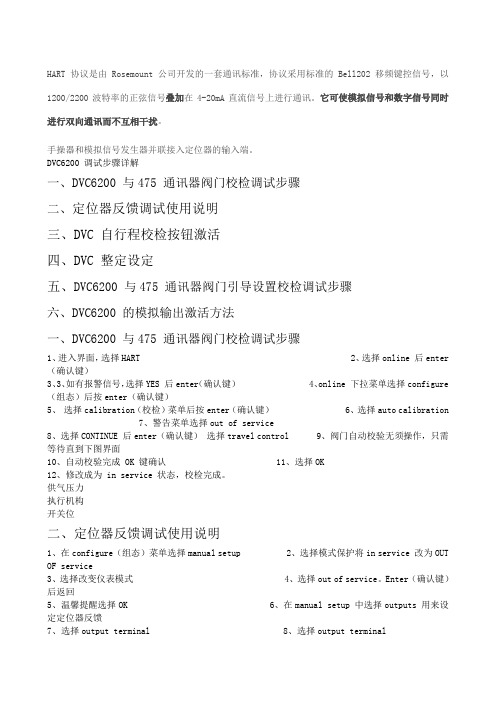
HART协议是由Rosemount公司开发的一套通讯标准,协议采用标准的Bell202移频键控信号,以1200/2200波特率的正弦信号叠加在4-20mA直流信号上进行通讯。
它可使模拟信号和数字信号同时进行双向通讯而不互相干扰。
手操器和模拟信号发生器并联接入定位器的输入端。
DVC6200 调试步骤详解一、DVC6200 与475 通讯器阀门校检调试步骤二、定位器反馈调试使用说明三、DVC 自行程校检按钮激活四、DVC 整定设定五、DVC6200 与475 通讯器阀门引导设置校检调试步骤六、DVC6200 的模拟输出激活方法一、DVC6200 与475 通讯器阀门校检调试步骤1、进入界面,选择HART2、选择online 后enter (确认键)3、3、如有报警信号,选择YES 后enter(确认键)4、online 下拉菜单选择configure (组态)后按enter(确认键)5、选择calibration(校检)菜单后按enter(确认键)6、选择auto calibration7、警告菜单选择out of service8、选择CONTINUE 后enter(确认键)选择travel control 9、阀门自动校验无须操作,只需等待直到下图界面10、自动校验完成 OK 键确认 11、选择OK12、修改成为 in service 状态,校检完成。
供气压力执行机构开关位二、定位器反馈调试使用说明1、在configure(组态)菜单选择manual setup2、选择模式保护将in service 改为OUT OF service3、选择改变仪表模式4、选择out of service。
Enter(确认键)后返回5、温馨提醒选择OK6、在manual setup 中选择outputs 用来设定定位器反馈7、选择output terminal 8、选择output terminal9、选择enable 后 enter(确认键) 10、一定要选择send 发送后完成反馈使用设置。
