拓普微TFT液晶显示模块系列应用手册20190214221930
TFT触摸屏使用说明

2一、.4寸TFT 触摸屏使用说明要正确使用TFT 触摸屏,需要借助相应的单片机实验板,这里,以顶顶电子开发板DD-900实验开发板为例进行介绍,值得庆幸的是,DD-900上设有3V 电压输出端,因此,可以方便地为TFT 触摸屏供电。
TFT 触摸屏模块介绍随着TFT 触摸屏价格的不断下降,其应用也越来越广泛,学习TFT 触摸屏现已成为一种时尚,以前,很多人只有在ARM 单片机中才能看到TFT 触摸屏的风采,现在,随着51单片机性能的提高,51单片机也能玩TFT 触摸屏了,这里,我们介绍的是一款2.4寸TFT 触摸屏模块,其正面与反面外形如图所示:这款触摸屏模块主要具备如下特点:1.2.4寸320*240 ,65K/262K 色;2.屏带PCB 板, PCB 板设有2.4寸液晶屏、SD 卡座、触摸屏控制芯片ADS7843,通过40脚插针将屏、卡座和触摸芯片功能引脚,引脚间距为2.54mm ,采用杜邦线可十分方便地与单片机进行连接。
PCB 引出脚排列及功能如图所示:3.屏设置为8位,用户也可根据实际情况设置为16位。
4.控制IC 为ILI9325。
二、供电及连接说明DD-900实验开发板采用的是5V 供电,因此,单片机应采用5V 单片机,如STC89C516RD+、STC12C5A60S2等,晶振采用30M ,注意TFT 要采用3V 供电,否则有可能烧屏,TFT 与单片机连接时可加限流电阻,电阻大小为470欧左右,也可以不加,但单片机不可设置为推挽模式,各引脚连接如下: TFT 触摸屏 DD-900实验开发板 说明 GND GND 屏与背光供电VCC 3V LED+ 3V DB8~DB15 P00~P07 液晶屏部分DB0~DB7不连接(这里采用是8位方式,不用连接)RS P26 WR P25 RD P24 CS P27 RES P23 D_CLK P21 触摸控制部分D_CS P20 D_DIN P22 D_BUSY P34 D_DOUT P33 D_Penirq (中断) P35 SD_OUT 根据程序进行定义 SD 卡座部分(前两个实验,此部分未采用) SD_SCK 根据程序进行定义SD_DIN根据程序进行定义SD_CS 根据程序进行定义注意:在TFT 的PCB 板上标有TFT 的引脚功能,一定要认清管脚与标注的对应关系。
拓普微单色产品列表Y2012~13-120627
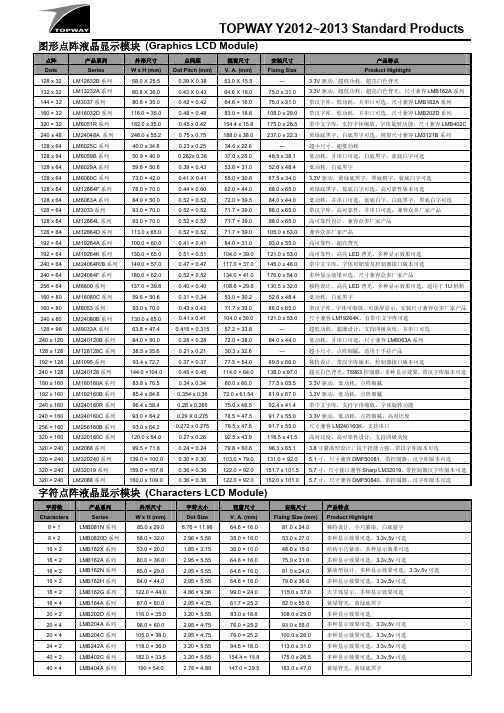
TOPWAY Y2012~2013 Standard Products 图形点阵液晶显示模块(Graphics LCD Module)点阵产品系列外形尺寸点间距视窗尺寸安装尺寸产品特点Dots Series W x H (mm) Dot Pitch (mm)V. A. (mm) Fixing Size Product Highlight128 x 32 LM12832B系列58.0 X 25.5 0.39 X 0.38 53.0 X 15.5 --- 3.3V驱动,超低功耗,超亮白色背光132 x 32 LM13232A系列80.8 X 36.0 0.43 X 0.43 64.6 X 16.0 75.0 x 31.0 3.3V驱动,超低功耗,超亮白色背光,尺寸兼容LMB162A系列144 × 32 LM3037系列80.8 × 35.0 0.42 × 0.42 64.6 × 16.0 75.0 x 31.0 带汉字库,低功耗,并串口可选,尺寸兼容LMB162A系列160 × 32 LM16032D系列116.0 × 35.0 0.48 × 0.48 83.0 × 18.6 108.0 x 29.0 带汉字库,低功耗,并串口可选,尺寸兼容LMB202D系列320 × 32 LM6051R系列182.0 x 35.0 0.45 x 0.42 154.4 x 15.8 175.0 x 26.5 带中文字库,支持字体缩放、字体旋转功能,尺寸兼容LMB402C 240 x 48 LM24048A 系列246.0 x 55.2 0.75 x 0.75 188.0 x 38.0 237.0 x 22.3 黄绿底黑字,白底黑字可选,视窗尺寸兼容LM3121B系列128 x 64 LM6025C系列40.0 x 34.8 0.23 x 0.25 34.6 x 22.6 --- 超小尺寸,超低功耗128 x 64 LM6059B系列50.9 × 40.9 0.282x 0.36 37.0 x 28.0 48.5 x 38.1 低功耗,并串口可选,白底黑字,蓝底白字可选128 x 64 LM6029A系列59.6 × 50.6 0.39 × 0.43 53.6 × 31.0 52.6 x 48.4 低功耗,白底黑字128 x 64 LM6060C系列73.0 × 42.0 0.41 X 0.41 55.0 × 30.6 67.5 x 34.0 3.3V驱动,黄绿底黑字,黑底橙字,蓝底白字可选128 x 64 LM12864F系列78.0 × 70.0 0.44 × 0.60 62.0 × 44.0 68.0 x 65.0 黄绿底黑字,蓝底白字可选,高可靠性版本可选128 x 64 LM6063A系列84.0 × 50.0 0.52 × 0.52 72.0 × 39.5 84.0 x 44.0 低功耗,并串口可选,蓝底白字,白底黑字,黑底白字可选128 × 64 LM3033系列93.0 × 70.0 0.52 × 0.52 71.7 × 39.0 88.0 x 65.0 带汉字库,高可靠性,并串口可选,兼容众多厂家产品128 x 64 LM12864L系列93.0 × 70.0 0.52 × 0.52 71.7 × 39.0 88.0 x 65.0 高可靠性设计,兼容众多厂家产品128 × 64 LM12864D系列113.0 x 65.0 0.52 × 0.52 71.7 × 39.0 105.0 x 53.0 兼容众多厂家产品192 × 64 LM19264A系列100.0 × 60.0 0.41 × 0.41 84.0 × 31.0 93.0 x 55.0 高可靠性,超亮背光192 × 64 LM19264K系列130.0 × 65.0 0.51 × 0.51 104.0 × 39.0 121.0 x 53.0 高可靠性,高亮LED背光,多种显示效果可选240 × 64 LM24064R/B系列149.0 × 57.0 0.47 × 0.47 117.0 × 37.0 145.0 x 46.0 带中文字库,字体可缩放及控制器接口版本可选240 × 64 LM24064F系列180.0 × 62.0 0.52 × 0.52 134.0 × 41.0 176.0 x 54.0 多种显示效果可选,尺寸兼容众多厂家产品256 × 64 LM6800系列137.0 × 39.6 0.40 × 0.40 108.6 × 29.6 130.5 x 32.0 独特设计,高亮LED背光,多种显示效果可选,适用于1U机箱160 × 80 LM16080C系列59.6 × 50.6 0.31 × 0.34 53.0 × 30.2 52.6 x 48.4 低功耗,白底黑字160 × 80 LM8053系列93.0 x 70.0 0.43 x 0.43 71.7 x 39.0 88.0 x 65.0 带汉字库,字体可缩放,可滚屏显示,安装尺寸兼容众多厂家产品240 x 80 LM24080B系列130.0 x 65.0 0.41 x 0.41 104.0 x 39.0 121.0 x 53.0 尺寸兼容LM19264K,有带中文字库可选128 × 96 LM9033A系列63.8 × 47.4 0.415 × 0.315 57.2 × 33.8 --- 超低功耗,超薄设计,支持四级灰度,并串口可选240 x 120 LM240120B系列84.0 × 50.0 0.28 × 0.28 72.0 × 38.0 84.0 x 44.0 低功耗,并串口可选,尺寸兼容LM6063A系列128 x 128 LM128128C系列38.5 x 35.6 0.21 x 0.21 30.3 x 32.6 --- 超小尺寸,点阵细腻,适用于手持产品192 × 128 LM1095系列93.4 x 72.7 0.37 × 0.37 77.5 × 54.0 89.5 x 66.0 独特设计,带汉字库版本,控制器接口版本可选240 × 128 LM240128系列144.0 ×104.0 0.45 × 0.45 114.0 × 64.0 138.0 x 97.0 超亮白色背光,T6963控制器,多种显示效果,带汉字库版本可选160 x 160 LM160160A系列83.8 x 76.5 0.34 x 0.34 60.0 x 60.0 77.5 x 65.5 3.3V驱动,低功耗,点阵细腻192 x 160 LM192160B系列85.4 x 84.6 0.354 x 0.36 72.0 x 61.54 81.9 x 67.0 3.3V驱动,低功耗,点阵细腻240 x 160 LM240160R系列96.4 x 58.4 0.28 x 0.265 75.0 x 46.5 92.4 x 41.4 带中文字库,支持字体缩放、字体旋转功能240 × 160 LM240160C系列93.0 × 64.2 0.29 X 0.275 78.5 × 47.5 91.7 x 55.0 3.3V驱动,低功耗,点阵细腻,高对比度64.2 0.272 x 0.275 78.5 x 47.5 91.7 x 55.0 尺寸兼容LM240160K,支持串口x256 × 160 LM256160B系列 93.0320 × 160 LM320160C系列120.0 x 54.0 0.27 x 0.26 92.5 x 43.9 118.5 x 41.5 高对比度,高可靠性设计,支持四级灰度320 × 240 LM2068系列99.5 × 71.8 0.24 × 0.24 79.8 × 60.6 96.3 x 65.1 3.8寸紧凑型设计,抗干扰能力强,带汉字库版本可选320 × 240 LM320240系列139.0 × 100.0 0.30 × 0.30 103.0 × 79.0 131.0 × 92.0 5.1寸,尺寸兼容DMF50081,带控制器,汉字库版本可选320 × 240 LM32019系列159.0 × 107.8 0.36 × 0.36 122.0 × 92.0 151.7 x 101.5 5.7寸,尺寸接口兼容Sharp LM32019,带控制器汉字库版本可选320 × 240 LM2088系列160.0 x 109.0 0.36 × 0.36 122.0 × 92.0 152.0 x 101.0 5.7寸,尺寸兼容DMF50840,带控制器,汉字库版本可选字符点阵液晶显示模块(Characters LCD Module)字符数产品系列外形尺寸字符大小视窗尺寸安装尺寸产品特点Characters Series W x H (mm) Dot Size V. A. (mm) Fixing Size (mm)Product Highlight8 × 1 LMB081N系列85.0 x 29.0 6.76 × 11.9664.6 × 16.0 81.0 x 24.0 独特设计,小巧紧凑,白底蓝字8 × 2 LMB0820D系列58.0 × 32.0 2.96 × 5.56 38.0 × 16.0 53.0 x 27.0 多种显示效果可选,3.3v,5v可选16 × 2 LMB162X系列53.0 × 20.0 1.85 × 3.15 36.0 × 10.0 48.0 x 15.0 结构小巧紧凑,多种显示效果可选16 × 2 LMB162A系列80.0 × 36.0 2.95 × 5.55 64.6 × 16.0 75.0 x 31.0 多种显示效果可选,3.3v,5v可选16 × 2 LMB162N系列85.0 × 29.0 2.95 × 5.55 64.6 × 16.0 81.0 x 24.0 紧凑型设计,多种显示效果可选,3.3v,5v可选16 × 2 LMB162H系列84.0 × 44.0 2.95 × 5.55 64.6 × 16.0 79.0 x 36.0 多种显示效果可选,3.3v,5v可选16 × 2 LMB162G系列122.0 × 44.0 4.86 × 9.56 99.0 × 24.0 115.0 x 37.0 大字体显示,多种显示效果可选16 × 4 LMB164A系列87.0 × 60.0 2.95 × 4.75 61.7 × 25.2 82.0 x 55.0 黄绿背光,黄绿底黑字20 × 2 LMB202D系列116.0 × 35.0 3.20 × 5.55 83.0 x 18.6 108.0 x 29.0 多种显示效果可选20 × 4 LMB204A系列98.0 × 60.0 2.95 × 4.75 76.0 × 25.2 93.0 x 55.0 多种显示效果可选,3.3v,5v可选20 × 4 LMB204C系列105.0 × 38.0 2.95 × 4.75 76.0 × 25.2 100.0 x 26.0 多种显示效果可选,3.3v,5v可选24 × 2 LMB242A系列118.0 × 36.0 3.20 × 5.55 94.5 × 18.0 113.0 x 31.0 多种显示效果可选,3.3v,5v可选40 × 2 LMB402C系列182.0 × 33.5 3.20 × 5.55 154.4 × 15.8 175.0 x 26.5 多种显示效果可选,3.3v,5v可选40 × 4 LMB404A系列190 × 54.0 2.78 × 4.89 147.0 × 29.5 183.0 x 47.0 黄绿背光,黄绿底黑字。
Riverdi 3.5英寸 TFT 显示屏参考手册说明书

ITEMCONTENTSUNITLCD Type TFT/Transmissive/Normally white / Size3.5Inch Viewing Direction12:00 (without image inversion) O’ Clock Gray Scale Inversion Direction 6:00O’ Clock Number of Dots 320 x (RGB) × 240 / Driver ICBT81x / Interface TypeSPI/QSPI/ Module Memory Size 1 MB (BT81x) + 64 Mb (external flash) / Color Depth16.7M/ Pixel Arrangement RGB Vertical Stripe/ Surface Treatment Anti-glare / Clear (for CTP) / Input Voltage3.3V3.5” EVE3 SERIES LCD TFTRiTFT-35 seriesRev.1.0 2018-10-22L C D T F T M o d u l e S p e c i f i c a t i o nNote 1: RoHS, REACH SVHC compliant Note 2: LCM weight tolerance: ± 5%.CONTENTS (2)1 MODULE CLASSIFICATION INFORMATION (3)2 ASSEMBLY GUIDE - INTEGRATION (3)2.1 Mounting frame (4)3 MODULE DRAWING (4)4 ABSOLUTE MAXIMUM RATINGS (5)5 ELECTRICAL CHARACTERISTICS (5)6 BACKLIGHT CHARACTERISTICS (5)7 ELECTRO-OPTICAL CHARACTERISTICS (5)8 INTERFACE DESCRIPTION (7)9 BT8x CONTROLLER SPECIFICATIONS (8)9.1 Serial host interface (8)9.2 Block Diagram (8)9.3 Host interface SPI mode 0 (9)9.4 Backlight driver block diagram (9)10 LCD TIMING CHARACTERISTICS (9)10.1 Clock and data input time diagram (9)10.2 Parallel RGB timing table (11)11 TOUCH SCREEN PANEL SPECIFICATIONS (11)11.1 Electrical characteristics (11)11.1.1 For capacitive touch panel (11)11.1.2 For resistive touch panel (12)11.2 Mechanical characteristics (12)11.2.1 For capacitive touch panel (12)11.2.2 For resistive touch panel (13)12 INSPECTION (13)12.1 Inspection condition (13)12.2 Inspection standard (14)13 RELIABILITY TEST (17)14 LEGAL INFORMATION (18)1. BRAND RV – Riverdi2. PRODUCT TYPE T – TFT StandardF – TFT Custom3. DISPLAY SIZE 35– 3.5”4. MODEL SERIAL NO. A (A-Z)5. RESOLUTION H– 320x240 px6. INTERFACE B – TFT + Controller BT81x7. FRAME N – No FrameF – Mounting Frame8. BACKLIGHT TYPE W – LED White9. TOUCH PANEL N – No Touch PanelR – Resistive Touch Panel C – Capacitive Touch Panel10. VERSION 00(00-99)RiTFT-35-RES RVT35AHBNWR00 BT816, resistive touch panelRiTFT-35-CAP RVT35AHBNWC00 BT815, capacitive touch panelRiTFT-35-FR RVT35AHBFWN00 BT816, no touch panel, mounting frame RiTFT-35-RES-FR RVT35AHBFWR00 BT816, resistive touch panel, mounting frame RiTFT-35-CAP-FR RVT35AHBFWC00 BT815, capacitive touch panel, mounting frame2.1Mounting frameFor dimension s 3.5”, 4.3”, 5.0” and 7.0” the product with mounting frame version is available. Thanks to the four catches attached to the side, frame provides strong assembly to the surface by mounting element (like the screw, see Figure 3). The frames are specially designed to fit Riverdi products perfectly. The diameter of the mounting hole is 3.5mm.Figure 1. Mounting frameRiTFT-35 series3MODULE DRAWING `` RiTFT-35© 2018 Riverdi Page 4 of 24 RiTFT-35 seriesRiTFT-35-FR© 2018 Riverdi Page 5 of 24 RiTFT-35 seriesRiTFT-35-CAP© 2018 Riverdi Page 6 of 24 RiTFT-35-CAP-FR© 2018 Riverdi Page 7 of 24 RiTFT-35-RES© 2018 Riverdi Page 8 of 24 RiTFT-35-RES-FR© 2018 Riverdi Page 9 of 24 4ABSOLUTE MAXIMUM RATINGSPARAMETER SYMBOL MIN MAX UNITSupply Voltage for Logic VDD 0 4.0 V Supply Voltage for LED Inverter BLVDD 0 7.0 VInput Voltage for Logic VIN 0 4.0 VLED forward current (each LED) IF - 25 mA Operating Temperature T OP-20 70 °C PARAMETER SYMBOL MIN TYP MAX UNIT NOTES Supply Voltage For Module VDD 3.0 3.3 3.6 VInput Voltage for LED Inverter BLVDD 2.8 5.0 5.5 VLED Backlight Current IDD backlight- 150 187 mA BLVDD=3.3V LED Backlight Current IDD backlight- 93 117 mA BLVDD=5V Input Voltage ' H ' level V IH0.7VDD - VDD VInput Voltage ' L ' level V IL0 - 0.2VDD VInput Current I In TBD mAInput Current for module with CTP I InC TBD mAITEM SYMBOL MIN TYP MAX UNIT Voltage for LED backlight V l- 19.2 20.4 V Current for LED backlight I l- 20 25 mA LED Life Time - 30000 50000 - HrsLNote 1. Contrast Ratio(CR) is defined mathematically as below, for more information see Figure .Contrast Ratio =Average Surface Luminance with all white pixels (P1,P2,P3,P4,P5) Average Surface Luminance with all black pixels (P1,P2,P3,P4,P5)Note 2. Surface luminance is the LCD surface from the surface with all pixels displaying white. For more information, see Figure .Lv = Average Surface Luminance with all white pixels (P1, P2, P3, P4, P5)Note 3.The uniformity in surface luminance δ WHITE is determined by measuring luminance at each test position 1 through 5, and then dividing the maximum luminance of 5 points luminance by minimum luminance of 5 points luminance. For more information, see Figure .δ WHITE =Minimum Surface Luminance with all white pixels (P1,P2,P3,P4,P5) Maximum Surface Luminance with all white pixels (P1,P2,P3,P4,P5)Note 4. Response time is the time required for the display to transition from white to black (Rise Time, Tr) and from black to white (Decay Time, Tf). For additional information see FIG 1. The test equipment is Autronic-Melchers’s ConoScope series.Note 5.CIE (x, y) chromaticity, the x, y value is determined by measuring luminance at each test position 1 through 5, and then make average value.Note 6. Viewing angle is the angle at which the contrast ratio is greater than 2. For TFT module the contrast ratio is greater than 10. The angles are determined for the horizontal or x axis and the vertical or y axis with respect to the z axis which is normal to the LCD surface. For more information see Figure .Note 7. For viewing angle and response time testing, the testing data is based on Autronic-Melchers’s ConoScope series. Instruments for Contrast Ratio, Surface Luminance, Luminance Uniformity, CIE the test data is based on TOPCON’s BM-5 photo detector.Note 8. For TFT module, Gray scale reverse occurs in the direction of panel viewing angle.Figure 2. The definition of response timeFigure 3. Measuring method for Contrast ratio, surface luminance, Luminance uniformity, CIE (x, y) chromaticityFigure 4.The definition of viewing angle8INTERFACE DESCRIPTION9BT8x CONTROLLER SPECIFICATIONSBT8x or EVE3 (Embedded Video Engine 3) simplifies the system architecture for advanced human machine interfaces (HMIs) by providing functionality for display, audio, and touch as well as an object oriented architecture approach that extends from display creation to the rendering of the graphics.9.1Serial host interfaceFigure 5.SPI interface connection Figure 6. QSPI interface connectionSPI Interface– the SPI slave interface operates up to 30MHz.Only SPI mode 0 is supported. The SPI interface is selected by default (MODE pin is internally pulled low by 47k resistor).9.2Block DiagramFigure 7.. BT8x Block diagram9.3Host interface SPI mode 0Figure 8. SPI timing diagramFor more information about BT8x controller please go to official BT8x website.https:///Products/ICs/BT81X.html9.4Backlight driver block diagramBacklight enable signal is internally connected to BT8x Backlight control pin. This pin is controlled by two BT8x’s registers. One of them specifies the PWM output frequency, second one specifies the duty cycle. Refer to BT8x datasheet for more information.Figure 9. Backlight driver block diagram10LCD TIMING CHARACTERISTICS10.1Clock and data input time diagramFigure 10. DE mode timing diagramBT8xFigure 11. SYNC mode timing diagramFigure 12. Timing diagram10.2Parallel RGB timing tableTiming parameter (VDD=3.3V, GND=0V, Ta=25˚C)PARAMETER SYMBOL MIN TYP MAX UNIT CONDITION CLK Clock Time T clk 1/Max(F CLK) - 1/Min(F CLK) ns -11TOUCH SCREEN PANEL SPECIFICATIONS11.1Electrical characteristicsNote: Avoid operating with hard or sharp material such as a ball point pen or a mechanical pencil except a polyacetal pen (tip R0.8mm or less) or a fingerITEM VALUE UNIT REMARKMin. Typ. Max.Linearity - - 1.5 % Analog X and Y directions Terminal Resistance 200 - 900 ΩX100 - 600 ΩY11.2Mechanical characteristicsNote 1: Force test condition, Input DC 5V on X direction, Drop off Polyacetal Stylus (R0.8), until output voltage stabilize, then get the R8.0mm Silicon rubber and do finger Activation force test. Next step, 9 points.Note 2: Measurement surface area conditions, Scratch 100,000 times straight line on the film with a stylus change every 20,000 times with Force: 250gf, Speed: 60mm/sec by R0.8 polaceteal stylus.Note 3: Pitting test, Pit 1, 000, 000 times on the film with R0.8 silicon rubber with Force: 250gf and Speed: 2 times/sec.Note 1: Force test condition, Input DC 5V on X direction, drop off Polyacetal Stylus (R0.8), until output voltage stabilize, then get the R8.0mm Silicon rubber and do finger Activation force test. Next step, 9 points.ITEM VALUE UNIT REMARKMin. Typ. Max.12INSPECTIONStandard acceptance/rejection criteria for TFT module.12.1Inspection conditionAmbient conditions:•Temperature: 25±°C•Humidity: (60±10) %RH•Illumination: Single fluorescent lamp non-directive (300 to 700 lux)Viewing distance:35±5cm between inspector bare eye and LCD.Viewing Angle:U/D: 45°/45°, L/R 45°/45°12.2Inspection standard Item Criterion Black spots, whitespots, light leakage,Foreign Particle(round Type)D=(x+y)2*Spots density: 10 mmSize < 5”Average Diameter Qualified QtyD < 0.2 mm Ignored0.2 mm < D < 0.3 mm 30.3 mm < D < 0.5 mm 20.5 mm < D 0Size >= 5”Average Diameter Qualified Qty D<0.2 mm Ignored0.2 mm < D < 0.3 mm 40.3 mm < D < 0.5 mm 20.5 mm < D 0Clear spotsSize >= 5”Average Diameter Qualified Qty D<0.2 mmIgnored 0.2 mm < D < 0.3 mm 4 0.3 mm < D < 0.5 mm 2 0.5 mm < D*Spots density: 10 mm Size < 5”Average Diameter Qualified Qty D < 0.2 mmIgnored 0.2 mm < D < 0.3 mm 3 0.3 mm < D < 0.5 mm 2 0.5 mm < D 0Polarizer bubblesSize < 5”Average Diameter Qualified Qty D < 0.2 mmIgnored 0.2 mm < D < 0.5 mm 3 0.5 mm < D < 1 mm 2 1 mm < D 0 Total Q’ty 3Size >= 5”Average Diameter Qualified Qty D<0.25 mmIgnored 0.25 mm < D < 0.5 mm 3 0.5 mm < D 0Electrical Dot DefectSize < 5”itemQualified Qty Black do defect 4 Bright dot defect 2 Total Dot 5Size >= 5”itemQualified Qty Black do defect 5 Bright dot defect 2 Total Dot 5Touch panel spotSize < 5”Average Diameter Qualified QtyD < 0.2 mm Ignored0.2 mm < D < 0.4 mm 50.4 mm < D < 0.5 mm 213RELIABILITY TESTNO. TEST ITEM TEST CONDITION REMARKS1 High Temperature Storage 80±2°C/240hours Note 22 Low Temperature Storage -30±2°C/240hours Note 1,2Note 1: Without water condensation.Note 2:The function test shall be conducted after 2 hours storage at the room temperature and humidity after removed from the test chamber.14LEGAL INFORMATIONRiverdi makes no warranty, either expressed or implied with respect to any product, and specifically disclaims all other warranties, including, without limitation, warranties for merchantability, non-infringement and fitness for any particular purpose. Information about device are the property of Riverdi and may be the subject of patents pending or granted. It is not allowed to copy or disclosed this document without prior written permission.Riverdi endeavors to ensure that the all contained information in this document are correct but does not accept liability for any error or omission. Riverdi products are in developing process and published information may be not up to date. Riverdi reserves the right to update and makes changes to Specifications or written material without prior notice at any time. It is important to check the current position with Riverdi.Images and graphics used in this document are only for illustrative the purpose. All images and graphics are possible to be displayed on the range products of Riverdi, however the quality may vary. Riverdi is no liable to the buyer or to any third part for any indirect, incidental, special, consequential, punitive or exemplary damages (including without limitation lost profits, lost savings, or loss of business opportunity) relating to any product, service provided or to be provided by Riverdi, or the use or inability to use the same, even if Riverdi has been advised of the possibility of such damages.Riverdi products are not fault tolerant nor designed, manufactured or intended for use or resale as on line control equipment in hazardous environments requiring fail – safe performance, such as in the operation of nuclear facilities, aircraft navigation or communication systems, air traffic control, direct life support machines or weapons systems in which the failure of the product could lead directly to death, personal injury or severe physical or environmental damage (‘High Risk Activities’). Riverdi and its suppliers specifically disclaim any expressed or implied warranty of fitness for High Risk Activities. Using Riverdi products and devices in 'High Risk Activities' and in any other application is entirely at the buyer’s risk, and the buyer agrees to defend, indemnify and hold harmless Riverdi from any and all damages, claims or expenses resulting from such use. No licenses are conveyed, implicitly or otherwise, under any Riverdi intellectual property rights.。
威图台式TFT液晶显示屏操作箱体产品技术手册说明书

产品技术手册适用于台式TFT液晶显示屏操作箱体操作箱体适用于最大尺寸达24˝ 的台式 TFT 液晶显示屏台式TFT液晶显示器操作箱体可确保,即便在恶劣的工业环境下,商务型TFT显示屏也可长持续顺利运转。
极致美观的设计使防水防尘的全方位专业防护更加完善。
与威图支托臂系统CP 60/120/180完美匹配。
◾钢板外壳经过浸入式涂漆处理且涂有超强抗腐蚀粉末◾经多重折边的箱体防护槽在开门时能阻止脏物和水侵入◾透明检视窗由单片安全玻璃构成◾后部维护入口◾集成式连接悬臂VESA 75/100◾用于单人安装的支托臂连接件◾用于放置最大尺寸达24˝的台式 TFT 液晶显示屏◾为比例为16:9/16:10最大尺寸为24˝ 的商用台式TFT液晶显示屏提供设计美观而有效的防护◾支托臂连接件,直径 130 mm,在加强板偏中心位置预制为模板◾高防护等级 IP 65◾侧面装饰板包括手柄功能24˝的台式TFT液晶显示屏威图产品获得了众多国际认可的证书及许可,并且达到了国际公认的最高质量标准。
◾所有元件均按照国际规定标准接受了最严格的检验◾全面的质量管理体系确保了产品始终如一的优良品质◾外部检验机构定期进行的生产检验确保产品始终符合国际质量标准在威图官网上可找到全部最新证书和许可。
通过在线的CAD零件库RiCAD-3D,威图为多种机柜和用途提供一站式的机械、空调、IT和能源解决方案。
为各个CAD 系统提供的专业数据提高了设备的设计效率,并缩短了安装时间。
◾CAD 数据可通过移动应用程序或在威图官网上使用◾可以通过电子信箱地址索取数据◾超过 70 种 CAD 格式可供选择◾直接链接到威图产品手册当前页,由此实现“ 一站式” 服务◾图纸精准到每一个细节并经过检验从而较好地确保了设计的安全性◾不必费时地进行重新设计,从而节约时间操作箱体用于最大尺寸达 24˝ 的台式 TFT 液晶显示屏1 2最佳的表面防护表面经过的三层处理提供最佳的防锈蚀保护。
LM19264A-AppNote-V0.1
LM19264A液晶显示模块应用参考深圳市拓普微科技开发有限公司版本 描述 日期 编者0.1 新版本2005-01-20 PanFeng目录1.简介 (3)2.电路连接原理简图 (3)3.指令操作 (3)4.指令集说明 (4)5.显示屏与显示区位置关系 (5)6.软件编程流程图 (5)附:参考程序 (6)1. 简介深圳市拓普微科技开发有限公司生产的LM19264A 系列点阵图形式液晶显示模块,采用S6B0108控制器。
STN/FSTN 、正显/负显、半透等多种显示方式。
模块大小100.0×60.0×14.0mm ,点阵数192×64dot 。
适配M6800操作时序电路,8bit 并口数据传输。
基本特性:-电源电压:单电源5.0V -显示分辨率:192×64dot -内置LCD 负压电路2. 电路连接原理简图采用AT89C52单片机同LM19264A 液晶模块通过并行I/O 口相连为例。
采用间接控制方式。
3. 指令操作M6800操作时序接口信号组合功能表如下:4. 指令集说明Code指令名称 R SR /WD B 7D B 6D B 5D B 4D B 3D B 2D B 1D B 0指令描述Display on/off 0 0 0 0 1 1111D 显示开关设置; D=0:关 D=1:开 Set Column(Y) Address 0 0 0 1Y address(0~63)列地址设置 Set Page(X) Address 0 0 1 0 1 11X address(0~7)页面地址设置 Set Display Start Line(Z address) 0 0 1 1Z address(0~63) 显示起始行设置Status Read 0 1 B u s y0 O n /O f fR e s e t0000读状态字;Busy=0:控制器准备好 Busy=1:控制器忙 On/Off=0:开显示状态 On/Off=1:关显示状态 Reset=0:正常工作状态 Reset=1:复位工作状态 Write Display Data1 0 Write Data 写显示数据 Read Display Data1 1Read Data读显示数据*1.更多详细指令参数设置请参考Samsung S6B0108 handbook.5. 显示屏与显示区位置关系显示屏的显示位置与显示缓冲区DDRAM的单元一一对应关系如下图.Display Area6.附:参考程序//本程序演示在屏幕上显示一192×64dot大小的图像,图像内容为“TOPWAY TECH.CO.,LTD. 拓普微科技开发有限公司 LM19264A”。
液晶显示模块使用手册.

液晶显示模块使用手册HD320240B-6型号:选 配 件 说 明■常温(0~50℃) □宽温(-20~+70℃)液晶片□黄绿膜 ■蓝膜 □灰膜 □黑白膜LED背光 ■白光 □翡绿光 □黄绿光 □蓝光 背 光EL背光 □白光 □蓝光 □CCFL背光负压电路 ■板载负压 □不带负压EL逆变器 □配备 □板载 ■不配备CCFL逆变器 □配备 ■不配备苏州华瑞光电科技有限公司www.frilcd.com项 目 标 准 尺 寸 单 位模 块 体 积 160L×109W×12.0H mm视 域 122×92 mm 行 列 点 阵 数 320×240 dots 点 距 离 0.36×0.36 mm 点 大 小0.33×0.33 mm一. 概述使用功能强大的RA8835作为控制器。
适配Intel8080系列和M6800 系列MPU 的两种操作时序电路,通过硬件设置,可选择二者之一。
4位显示数据线,传输数据迅速;具有强大的作图功能;支持文本显示、图形显示以及图形和文本混合显示;具备简捷的MPU 接口和功能齐全的控制指令集。
采用SMT 工艺制作,结构稳固,使用寿命长。
二.特性1. 工作电压:5.0V±10%2. 显示模式:320×240图形点阵3. 内建32KB 显示RAM4. 内部固化的160种5×7点阵的字符,用户最多可自建64个5×7点阵的字符5.文本显示、图形显示以及文本与图形混合显示功能三.外形尺寸1. 外形图HD320240B-6四.硬件说明1. 模块接口:管脚名称管脚编号CN1 J1电平功能描述1 VSS VSS 0V电源地2 VDD VDD5.0V电源电压3 V0 V0负压对比度调节端4 VOUT VOUT 负压负电源5 A0(=RS) A0(=RS) H/L 高:选择数据寄存器低:选择指令寄存器6 /RW /RWH/L 80时序:写信号;低有效68时序:/RW=R/W,读写选择信号端7 /RD /RDH/L 80时序:读信号;低有效68时序:/RD=E,操作使能信号DB0 DB08~~~DB715 DB7H/L数据总线16 CS CSH/L片选信号;低有效17 RESET RESET H/L复位信号;低有效18 FG NC 铁框地19 LED+ LED+ 5V 背光正极20 LED- LED- 背光负极管脚名称管脚编号CN1 J1电平功能描述1 ~ 4 D0~D3D0~D3H/L数据线5 DISPOFFB DISPOFFB H/L显示开关控制6 FLM FLM H/L行起始信号(帧信号)7 M MH/L LCD交变驱动信号8 CL1 CL1H/L显示数据锁存脉冲信号9 CL2 CL2H/L显示数据位移脉冲信号10 VDD VDD5.0V电源电压11 VSS VSS 0V电源地12 VOUT VOUT 负压负电源13 V0 V0负压对比度调节端14 FG FG 铁框地2. 原理简图3. 最大工作范围1)逻辑工作电压(Vdd): 5V±10%2)电源地(GND):0V3) LCD驱动电压(V op): 30Vmax4)输入电压:0~Vdd4. 电气特性(测试条件,Vdd=5.0±10%)1)输入高电平(Vih):0.8Vdd~Vdd2)输入低电平(Vil):Vss~0.2Vdd3)输出高电平(V oh): 2.4Vmin4)输出低电平(V ol): 0.4Vmax5)模块工作电流:95~109mA (不含背光)6)侧白光工作电流: 140mA五.模块主要硬件构成说明1. SEL1脚接低时选择Intel8080时序,接高时选择M6800时序也可由软件设置2. 忙标志(BF)MPU访问RA8835不需要判断其是否“忙”,随时准备接受MPU访问并在内部时序下及时地把MPU发来的数据、指令就位。
液晶显示模块用户手册说明书
DOT MATRIXLIQUID CRYSTAL DISPLAYMODULECOMPANY NAME : 伍豐科技USER‘MANUALSBS02002D0 SerialSBS02002D0LEW10(英日英日文版文版) LCD Module Description: SBS02002D0LEW20(英歐英歐文版文版)SBS02002D0LEW30(英俄英俄文版文版)PROPOSED BYAPPROVEDDesignApprovedSDEC TECHNOLOGY CORP.ADDRESS: 10F, No. 100, Shing De Rd., San Chung City 241Taipei Hsien, Taiwan R.O.C.TEL: 886-2-2999-2512/886-2-8512-1288 FAX: 886-2-2999-2510/886-2-8512-2828LCM SAMPLE APPROVAL (液 晶 顯 示 模 組組 樣 品 確 認 書)1. P ART A:FILLED BY SDEC TECH (由SDEC 填寫填寫))1) COMPANY NAME (客戶名稱客戶名稱):):):伍豐科技股份有限公司伍豐科技股份有限公司2) SDEC ITEM NO.(產品型號產品型號)):SBS02002D0LEW10/SBS02002D0LEW20/SBS02002D0LEW30 3) CUSTOMER ITEM NO.(客戶產品型號客戶產品型號)):RD9000PH03AJ/RD9000PH03AI/RD9000PH03AK 4) LCM Function (LCM 內容):ALCD TYPE (LCD 種類):□ TN, □ HTN, ■ STN, □ FSTN ( □ POSITIVE/正向正向,,■ NEGATIVE/反向, □ BLACK MASK/內黑絲印) B VIEWING AREA (視角方向):□ 3H, □ 6H, □ 9H, ■ 12HC POLARIZER COLOR (偏光板顏色):□ GRAY/灰色, □ YELLOW GREEN/黃綠色黃綠色,,■ BLUE/藍色, □ BLACK/黑色D BACKLIGHT COLOR (背光顏色):□ YELLOW GREEN/黃綠光, □ ORANGE/橘光□ RED/紅光, □ BLUE/藍光, □ GREEN/翠綠光, ■ WHITE/白光E TEMPERATURE (溫度):□ NORMAL/常溫, ■ WIDE/廣溫F Rom Code CheckSum :AF37H (Check Sum is not Read Back).GSBS02002D0LEW10 : SPLC780D1-01 CONTROL IC (控制IC): SBS02002D0LEW20 : SPLC780D1-03SBS02002D0LEW30 : SPLC780D1-02 SAMPLE DELIVERY DATE (出樣日期出樣日期):):2010.09.20 2.PART B:FILLED BY CUSTOMER (請客戶填寫請客戶填寫))CHECK LIST ITEMS (檢查項目檢查項目):):OK NG REASON (原因原因)) 1).LCM SIZE AND THICKNESS:(LCM 尺寸及厚度尺寸及厚度)): □ □ ________ 2).POLARIZER COLOR :(:(偏光板色澤偏光板色澤偏光板色澤):): □ □ ________ 3).ELECTRO CHARACTERISTIC :(:(電氣特性電氣特性電氣特性):): □ □ ________ 4).VIEWING AREA (視角範圍視角範圍):):□ □ ________ 5).BACKLIGHT ILLIMINATION (背光亮度背光亮度):): □ □ ________ 6).TEMPERATURE RANGE (溫度範圍溫度範圍):):□□________APPROVED BY (批准批准):): DATE OF APPROVAL (批准日期批准日期):):REVISION RECORDRevisionPage Contents2008.07 Mass Production2009.03A1. Change Instruction Code Table2. Add “€”Pattern in Font Table 07H & 0FH3. PCB R15~R25:100Ω change to 0Ω 2009.05A2 1. Add Customer Item No. 2 2. Add Rom code CheckSum.3. PCB Rev No :Rev.3 up date to Rev.4 2010.09A1. Initial Delay 30ms2. PCB U4:AT89C2051 change to SM894051C 23. CheckSum :AF37HCONTENTSPAGE ●LCM Sample Approval 2●REVISION RECORD 31. Mechanical Specification 52. Mechanical Diagram 53. Interface Pin Connections 54. Block Diagram 55. Backlight Electronic Characteristics 56. Absolute Maximum Ratings 67. Electrical Characteristics 68. Optical Characteristics 69. Optical Definitions 610. Instruction Set 711.Instruction Description 812. User Font Patterns 1113. Character Generator ROM Map13.1 SBS02002D0LEW10 Font Table 1213.2 SBS02002D0LEW20 Font Table 1313.3 SBS02002D0LEW30 Font Table 1414. Reliability Condition 1515. Function Test & Inspection Criteria 1516. Test – Normal Temperature 1817. Test – Wide Temperature 1918. Precautions Against Product Handling 2019. Warranty 211.Mechanical SpecificationITEM STANDARD VALUE UNITNUMBER OF CHARACTERS 20 CHARACTERS X 2 LINES --CHARACTER FORMAT 5 X 8 DOTS --MODULE DIMENSION167.0 (W) X 46.0 (H) X 18.5(Max) (T) mm EDGE LED BACKLIGHTVIEWING DISPLAY AREA 123.0 (W) X 23.0 (H) mmACTIVE DISPLAY AREA 118.85 (W) X 19.0 (H) mmCHARACTER SIZE 4.85 (W) X 9.32 (H) mmCHARACTER PITCH 6.00 (W) X 9.77 (H) mmDOT SIZE 0.93 (W) X 1.11 (H) mmDOT PITCH 0.98 (W) X 1.16 (H) mmNO SYMBOL FUNCTION1 VDD DC +5V2 VSS GND ( 0V)3 DI Series Data Input4 FGND FRAME GND5. Backlight Electronic CharacteristicsTa=25℃ITEM SYMBOL Ratings UNIT Absolute maximum forward current IFm 2*80 mA Peak forward current IFp 2*160 mAReverse Voltage Vr 4 VPower Dissipation Pd 2*160 mW Operating Temperature Range Top -20~+70 ℃Storage Temperature Range Tst -30~+80 ℃ITEM SYMBOL MIN. TYPE MAX. UNIT CONDITION Forward Voltage VF 3.8 4.0 4.2 V IF=2*40mAReverse Current Ir -- -- 2*200 μA Vr=4VLuminance LV 500 600 -- cd/m2IF=2*40mARange X=0.25~0.29 , Y=X-0.0135~X+0.0175 IF=2*40mA6. Absolute Maximum RatingsITEM SYMBOLMIN. TYPE MAX. UNIT INPUT VOLAGEVI VSS ── VDD V SUPPLY VOLTAGE FOR LOGIC VDD-VSS ── 5.0 6.5 V SUPPLY VOLTAGE FOR LCD VDD-VO ── ── 6.5 V NORMAL TEMPERATURE RANGE OPTERATING 0~+50 STORAGE -10~+60 ℃ TN HTN WIDE TEMPERATURE RANGE OPTERATING -20~+70 STORAGE -30~+80 ℃ STN FSTNWIDE TEMPERATURE RANGE OPTERATING-20~+70STORAGE-30~+80℃STATIC ELECTRICITYBe sure that you are grounded when handing LCM.7. Electrical CharacteristicsITEMSYN CONDITIONMIN. TYPE MAX. UNIT SUPPLY VOLTAGE FOR LOGIC VDD -VSS ── 4.5 5.0 5.5 V SUPPLY VOLTAGE FOR LCD VDD -VO Ta =-20℃ Ta =25℃ Ta =+70℃ ── 4.1 ── 4.9 4.3 3.9 ── 4.5 ── V V V INPUT HIGH VOLTAGE VIH ── 2.2 ── VDD V INPUT LOW VOLTAGE VIL ── 0 ── 0.6 V OUTPUT HIGH VOLTAGE VOH ── 2.4 ── ── V OUTPUT LOW VOLTAGE VOL ── ── ── 0.4 V SUPPLY CURRENT (Without Backlight)IDDVDD=+5V──3.04.5mA8. Optical Characteristics Ta at 25℃ITEMSYM CONDITIONMIN. TYPE MAX.UNIT VIEW ANGLE (TOP /BOTTOM) θ1~θ2 CR ≧5 -35o ── 45odeg. VIEW ANGLE (LEFT /RIGHT)φ1.φ2 CR ≧5 -35o ── 35o deg. CONTRAST RATIO CR ── ── 8 ── ── RESPONSE TIME (RISE) TON /Tr ── ── 170 ── mS RESPONSE TIME (DECAY)TOFF /Tf────220──mS9. Optical Definitions10. COMMAND SETC ommand C ode(hex)D escriptionESC @ 1B 40 Initialize.ESC _ n 1B 5F n (n=0, 1) Cursor hide/Show.HT 09 Cursor right.ESC [ C 1B 5B 43 Cursor right.BS 08 Cursor left.ESC [ D 1B 5B 44 Cursor left.LF 0A Cursor down.ESC [ B 1B 5B 42 Cursor down.ESC [ A 1B 5B 41 Cursor up.ESC [ H 1B 5B 48 Cursor homeHOM 0B Cursor homeCR 0D Cursor left-endESC [ L 1B 5B 4C Cursor left-end.ESC [ R 1B 5B 52 Cursor right-end.ESC [ K 1B 5B 4B Cursor to the bottom.ESC C n d0….d7 1B 43 n d0….d7 (00h<=n<=07h) Create custom character patternsESC l x y 1B 6C x y (01h<=x<=14h, 01h<=y<=02h) Cursor to specified position.CLR 0C Clear screen.ESC Q A 1B 51 41 [datax15] 0D Set string display mode, write string to upper line.ESC Q B 1B 51 42 [datax15] 0D Set string display mode, write string to lower line.ESC DC1 1B 11 Overwrite modeESC DC2 1B 12 Vertical scroll modeESC DC3 1B 13 Horizontal scroll modeCAN 18 Clear cursor line, clear string modeESC W s x1 x2 y 1B 57 s x1 x2 yS = 00h , 01h01h<=x1<=x2<=14h,Y = 01h , 02hSet/cancel the window range inHorizontal scroll modeThere are basically four display modes for the LCD. The user may choose the mode that is most appropriate for the application.Overwrite Mode:******************************************************************************************* from left to right, if it is at the end of the Line, it moves to the beginning of the other line. Characters are displayed at the Current cursor position, overwriting what is originally there, the cursor is then moved to the next position.Vertical Scroll Mode:If the cursor is at the upper line it behaves like the overwrite mode. When it is at the end of the lower line, the next character would scroll the content of the lower line to the upper line, the lower line is cleared and the cursor is moved to the beginning of the lower line.Horizontal Scroll Mode:In this mode the cursor stays in what ever line it is at, unless changed by cursor Movement commands. When the cursor is not at the end of the line, the input Character is displayed at current cursor position, the cursor is then moved right. Once at the end of the line, subsequent character input would scroll the current Line left one position, and the new character is displayed at the end position. There is also a command, ESC W, to set display window in this mode. The effective display line would be limited within the window as defined by the command.String Mode:This mode is perhaps the simplest used. The two display lines are treated independently. Only two commands, ESC Q A and ESC Q B, are needed. ESC Q A followed by a string on the upper line, left aligned. A CR (0DH) character terminates the command. If the string is less than twenty characters in length, the rest of display line is padded with plank. ESC Q B does the same for the lower display line. The only other commands active in this mode are CLR and CAN. CLR would clear the display and change the LCD into overwrite mode. CAN clears the last line that was changed and change the LCD into overwrite mode. The initialization command, ESC @, has no effect in this mode.11. Instruction Description11.1 ESC @ / Initialize display /ASCII Format:ESC @DEC Format:[027] [064]HEX Format:[1BH][40H]Description:Clear the data in the input buffer and reset setting to power on defaults.11.2 CLR / Clear display screen, and clear string mode /ASCII Format:CLRDEC Format:[012]HEX Format:[0CH]Description:Clear all the characters displayed, clear string mode.11.3 CAN / Clear cursor line, and clear string mode /ASCII Format:CANDEC Format:[024]HEX Format:[18H]Description:Clear the line where the cursor is at, clear string mode.11.4 ESC Q A d1d2d3…dn CR / Set string display mode, write string to upper line /ASCII Format:ESC Q A d1d2d3…dn CRDEC Format:[027][081] [065] d1d2d3…dn [013]HEX Format:[1BH] [51H] [41H] d1d2d3…dn [0DH] {20h<=dn<=ffh ,1<=n<=20}Description:Set string display mode, write to upper line.The string display mode can be cancelled with CLR or CAN.11.5 ESC Q B d1d2d3…dn CR / Set string display mode, write string to lower line /ASCII Format:ESC Q B d1d2d3…dn CRDEC Format:[027] [081][066] d1d2d3…dn [013]HEX Format:[1BH][51H][42H] d1d2d3…dn [0DH] {20h<=dn<=ffh ,1<=n<=20}Description:Set string display mode, write to lower line.The string display mode can be cancelled with CLR or CAN.11.6 ESC [ A / Move cursor up /ASCII Format:ESC [ ADEC Format:[027] [091] [065]HEX Format:[1BH] [5BH] [41H]Description:move the cursor up one line.When the cursor is at the upper line, this command operates differently depending on the display mode:a. Overwrite mode: The cursor is moved to the same column on the lower lineb. Vertical scroll mode: The characters displayed on the upper line are scrolled to the lower line, and the upper line iscleared. The cursor remains at the same position.c. Horizontal scroll mode: The cursor is not moved.11.7 ESC [ B / Move cursor down /ASCII Format:ESC [ BDEC Format:[027][091][066]HEX Format:[1BH][5BH][42H]Description:move the cursor down one line.When the cursor is at the lower line, this command operates differently depending on the display mode:a. Overwrite mode: The cursor is moved to the same column on the upper line.b. Vertical scroll mode: The characters displayed on the upper line are scrolled to the lower line, and the upper line iscleared. The cursor remains at the same position.c. Horizontal scroll mode: The cursor is not moved.11.8 ESC [ C / Move cursor right /HTASCII Format:ESC [ CHTDEC Format:[027][091][067][009]HEX Format:[1BH][5BH][43H][09H]Description:Move the cursor one position to the right.When the cursor is at the right end, this command operates differently depending on the display mode:a. Overwrite mode: The cursor moves to the left end of the other line.b. Vertical scroll mode: When the cursor is at the upper right end, it is moved to the lower left end. When the cursor is atthe lower right end, the lower line message is moved to the upper line. The lower line is cleared,and the cursor moved to the lower right end.c. Horizontal scroll mode: All characters on the current line are scrolled one to the left in the window. The cursor is notmoved but the character area at the right end of the windows is cleared.11.9 ESC [ D / Move cursor left /BSASCII Format:ESC [ DBSDEC Format:[027][091][068][008]HEX Format:[1BH][5BH][44H][08H]Description:Move the cursor one position to the left.When the cursor is at the left end, this command operates differently depending on the display mode:a. Overwrite mode: The cursor moves to the right end of the other line.b. Vertical scroll mode: When the cursor is at the lower left end, it is moved to the upper right end. When the cursor is atthe upper right end, the upper line message is moved to the lower line. The upper line is cleared,and the cursor moved to the upper right end.c. Horizontal scroll mode: All characters on the current line are scrolled one to the right in the window. The cursor is notmoved but the character area at the left end of the windows is cleared .11.10 ESC _ n / Set cursor ON or OFF /ASCII Format:ESC _ nDEC Format:[027] [095] n {0<=n<=1}HEX Format:[1BH] [5FH] nDescription:Set cursor ON or OFF.When n = 0, cursor is set to OFF.When n = 1, cursor is set to ON.11.11 ESC [ H / Move cursor to home position /HOMASCII Format:ESC [ HHOMDEC Format:[027][091][072][011]HEX Format:[1BH][5BH][48H][0BH]Description:Move the cursor to the left -most position on the upper line.11.12 ESC [ L / Move cursor to left-most position /CRASCII Format:ESC [ LCRDEC Format:[027][091][076][013]HEX Format:[1BH][5BH][4CH][0DH]Description:Move the cursor to the left-most position on the current line.11.13 ESC [ R / Move cursor to the right-most position /ASCII Format:ESC [ RDEC Format:[027][091][082]HEX Format:[1BH][5BH][52H]Description:Move the cursor to the right -most position on the current line.11.14 ESC [ K / Move cursor to the specified position /ASCII Format:ESC [ KDEC Format:[027][091][075]HEX Format:[1BH][5BH][4BH]Description:Move the cursor to the right -most position on the lower line.11.15 ESC l X Y / Move cursor to the specified position /ASCII Format:ESC l X YDEC Format:[027][108] X Y {01H<=X<=14H, 01H<=Y<=02H}HEX Format:[1BH][6CH] X YDescription:Move the cursor to the X-th column on the Y-th line.11.16 ESC W s x1 x2 y / Set or cancel the windows range at horizontal scroll mode /ASCII Format:ESC W s x1 x2 yDEC Format:[027][087][000][027][087][001] x1 x2 y {01h<=x<=14h , 01h<=y<=02h}HEX Format:[1BH][57H][00H][1BH][57H][01H] x1 x2 yDescription:Set or cancel the window range on the display screen.When s = 0, window is cancelled.When s = 1, window is set, where x1 and x2 set the position of the left-most and the right-most columns of thewindow.y sets the upper or lower line.The window is effective in the horizontal scroll mode.11.17 ESC C n d0….d7 / Create character pattern /ASCII Format:ESC C n d0….d7DEC Format:[027][067] n d0….d7 {00h<=n<=07h}HEX Format:[1BH][43H] n d0….d7Description:Create custom character patterns.n specifies which custom character to be generated.d0..d7 specify the bit pattern for the character to be generated.There are eight customer definable characters. They are numbered from 0 to 7, corresponding to character codes00h to 07h, and are duplicated at character codes 08h to 0Fh.The relation between n and the character codes is as below:n Char code N Char code0 00h 0 08h1 01h 1 09h2 02h 2 0Ah3 03h 3 0Bh4 04h 4 0Ch5 05h 5 0Dh6 06h 6 0Eh7 07h 7 0FhBelow is an example for generating as a custom character:NO 7 6 5 4 3 2 1 0 (Bit Pattern) Data Value in hexd0 * * * 1 1 1 1 1 1FHd1 * * * 1 0 0 0 1 11Hd2 * * * 1 0 0 0 1 11Hd3 * * * 1 0 0 0 1 11Hd4 * * * 1 0 0 0 1 11Hd5 * * * 1 0 0 0 1 11Hd6 * * * 1 0 0 0 1 11Hd7 * * * 1 1 1 1 1 1FH11.18 ESC DC1 / Set overwrite mode /ASCII Format:ESC DC1DEC Format:[027][017]HEX Format:[1BH][11H]Description:Set the display to overwrite mode. This is the default power on display mode.11.19 ESC DC2 / Set vertical scroll mode /ASCII Format:ESC DC2DEC Format:[027][018]HEX Format:[1BH][12H]Description:Set the display to vertical scroll mode.11.20 ESC DC3 / Set horizontal scroll mode /ASCII Format:ESC DC3DEC Format:[027][019]HEX Format:[1BH][13H]Description:Set the display to horizontal scroll mode.12. User Font Patterns ( CG RAM Character )Character Code (DD RAM data) CG RAM Address Character Pattern (CG RAM data) Hi 7 6 5 4 3 2 1 0 Lo 5 4 3 2 1 0 Hi 7 6 5 4 3 2 1 0 Lo0 0 0 0 x 0 0 00 0 00 0 10 1 00 0 0 0 1 11 0 01 0 11 1 01 1 1x x x 1 1 1 1 0x x x 1 0 0 0 1x x x 1 0 0 0 1x x x 1 1 1 1 0x x x 1 0 1 0 0x x x 1 0 0 1 0x x x 1 0 0 0 1x x x 0 0 0 0 00 0 0 0 x 0 0 10 0 00 0 10 1 00 0 1 0 1 11 0 01 0 11 1 01 1 1x x x 1 0 0 0 1x x x 0 1 0 1 0x x x 1 1 1 1 1x x x 0 0 1 0 0x x x 1 1 1 1 1x x x 0 0 1 1 0x x x 0 0 1 0 0x x x 0 0 0 0 0---------------- ---------------- --------------------------------0 0 0 0 x 1 1 10 0 00 0 10 1 01 1 1 0 1 11 0 01 0 11 1 01 1 113.Character Generator ROM Map13.1 SBS02002D0LEW10 (英日文版)Font Table13.2 SBS02002D0LEW20 (英歐文版)Font Table13.3 SBS02002D0LEW30 (英俄文版)Font Table14.Reliability Condition15.Functional Test & Inspection Criteria15.1 Sample planSample plan according to MIL-STD-105D level 2, and acceptance/rejection criteria is. Base on: Major defect: AQL 0.65 Minor defect: AQL 2.5 15.2 Inspection conditionViewing distance for cosmetic inspection is 30cm with bare eyes, and under an environment of 800 lus (20W) light intensity. All direction for inspecting the sample should be within 45°against perpendicular line.15.3 Definition of Inspection Zone in LCDZone A: Character / Digit area Zone B: Viewing area except Zone A (Zone A + Zone B = minimum Viewing area) Zone C: Outside viewing area (invisible area after assembly in customer’s product)Note: As a general rule, visual defects in Zone C are permissible, when it is no trouble forquality and assembly of customer’s product.15.4 Major DefectAll functional defects such as open (or missing segment), short, contrast differential, excess power consumption, smearing, leakage, etc. and overall outline dimension beyond the drawing. Are classified as major defects.15.5 Inspection Parameters And Glass Pixel(偏光板和玻璃圖像檢驗)NO Polarizer(偏光板) Criteria1Black or White spots And Piercing(黑/白點和刺孔)D/面積=(Length/長度+Width/寬度)/2 => * :Disregard(忽略)Dimension (面積) Acceptable number (可接受數量)D <0.15 * 0.15≦D ≦0.2 4 0.2≦D ≦0.25 2 D ≦0.30 2Scratch (刮傷)*0.04≧W * 3.0≧L 0.06≧W 4 2.0≧L 0.08≧W 2-0.1≧WX :Length(長度) Y :Width(寬度) *:Disregard(忽略)X(mm)Y(mm)Acceptable number (可接受數量)3Air Bubbles(between glass & polarizer) 氣泡(玻璃跟偏光板之間)D ≦0.15 * 0.15<D ≦0.25 20.25<D*:Disregard (忽略)Dimension (面積) Acceptable number (可接受數量)4Glass of Pixel (玻璃的圖像)(1)Pixel shape (with Dent) /圖像凹度●Less than 0.152 mm is no counted (小於0.152mm 者不計)(2)Pixel shape (with Projection)/圖像凹度Should not be connected next pixel(點與點間不可先連接)(3)Deformation/變形( X + Y ) / 2 ≦ 0.15mm ●Less than 0.1 mm is no counted (小於0.15mm 者不計)(4) Deformation/變形( X + Y ) / 2 ≦ 0.3mm ●Less than 0.3 mm is no counted (小於0.3mm 者不計)(在不改變原先顯示下進行以下測試操作)Conditions : Unless otherwise specified, test will be conducted under the following condition. Temperature : 20±5 ℃ Humidity : 40±5%RHTests will be not conducted under functioning state.(條件:除非其他特殊情況,否則測試將以溫度:20±5 ℃,濕度:40±5%RH 為主)NO ParameterConditionsNotes 1 High Temperature Operating50℃±2 ℃ , 96 hrs (operation state)(96小時,溫度50℃±2 ℃電源開啟的操作情況下) 2 Low Temperature Operating0℃±2 ℃ , 96 hrs (operation state)(96小時,溫度0℃±2 ℃電源開啟的操作情況下) 1 3 High Temperature Storage60℃±2 ℃ , 96 hrs(96小時,溫度60℃±2 ℃電源關閉靜態操作下) 2 4 Low Temperature Storage -10℃±2 ℃ , 96 hrs(96小時,溫度-10℃±2 ℃電源關閉靜態操作下) 1 , 2 5Damp ProofTest40℃±2 ℃ , 85 ~ 90%RH , 96hr(96小時,溫度:40℃±2 ℃,濕度:85~90%RH 電源關閉靜態操作下)1 , 26Vibration TestTotal fixed amplitude : 1.5 mm (完全固定輻射:1.5mm) Vibration Frequency : 10 ~ 55 Hz (震動頻率:10~55 Hz) One cycle 60 seconds to 3 directions of X , Y , Z foreach 15 minutes (每一個循環 X ,Y ,Z 軸方向各做60秒,連續做5次,共計15 分鐘)37Shock Test To be measured after dropping from 60cm high on the concrete surface in packing state. (包裝材從60公分高的地方向地面落下)Dropping method comer dropping (角落落下方式)A comer :once Edge dropping (側邊落下)B ,C ,D edge : onceFace dropping (表面落下)E ,F ,G face : onceNote 1:No dew condensation to be observed. (不要在”水氣凝結點”下觀察) Note 2:The function test shall be conducted after 4 hours storage at the normalTemperature and humidity after removed from the test chamber(從實驗室移出後,放在一般常溫 (溫度:25℃,濕度:45%RH), 且四小時後通電流或電壓,看它是否能正常動作)(在不改變原先顯示下進行以下測試操作)Conditions : Unless otherwise specified, test will be conducted under the following condition. Temperature : 20±5 ℃ Humidity : 40±5%RHTests will be not conducted under functioning state.(條件:除非其他特殊情況,否則測試將以溫度:20±5 ℃,濕度:40±5%RH 為主)NO ParameterConditionsNotes 1 High Temperature Operating70℃±2 ℃ , 96 hrs (operation state)(96小時,溫度70℃±2 ℃電源開啟的操作情況下) 2 Low Temperature Operating-20℃±2 ℃ , 96 hrs (operation state)(96小時,溫度-20℃±2 ℃電源開啟的操作情況下) 1 3 High Temperature Storage80℃±2 ℃ , 96 hrs(96小時,溫度80℃±2 ℃電源關閉靜態操作下) 2 4 Low Temperature Storage -30℃±2 ℃ , 96 hrs(96小時,溫度-30℃±2 ℃電源關閉靜態操作下) 1 , 2 5Damp ProofTest40℃±2 ℃ , 85 ~ 90%RH , 96hr(96小時,溫度:40℃±2 ℃,濕度:85~90%RH 電源關閉靜態操作下)1 , 26Vibration TestTotal fixed amplitude : 1.5 mm (完全固定輻射:1.5mm) Vibration Frequency : 10 ~ 55 Hz (震動頻率:10~55 Hz) One cycle 60 seconds to 3 directions of X , Y , Z foreach 15 minutes (每一個循環 X ,Y ,Z 軸方向各做60秒,連續做5次,共計15 分鐘)37Shock Test To be measured after dropping from 60cm high on the concrete surface in packing state. (包裝材從60公分高的地方向地面落下)Dropping method comer dropping (角落落下方式)A comer :once Edge dropping (側邊落下)B ,C ,D edge : onceFace dropping (表面落下)E ,F ,G face : onceNote 1:No dew condensation to be observed. (不要在”水氣凝結點”下觀察) Note 2:The function test shall be conducted after 4 hours storage at the normalTemperature and humidity after removed from the test chamber(從實驗室移出後,放在一般常溫 (溫度:25℃,濕度:45%RH), 且四小時後通電流或電壓,看它是否能正常動作)事項]:產品使用注意事項18. Precautions Against Product Handling [產品使用注意The following precautions will guide you in handling our product correctly.[下列警戒引導正確地使用產品]18.1 Care of the LCD module against static electricity discharge. [LCD模組靜電注意事項]18.1.1 When working with the module, be sure to ground your body and any electricalequipment you may be using. We strongly recommend the use of anti static mats (made ofrubber), to protect work tables against the hazards of electrical shock.[操作模組時,避免操作者身體接地及任何造成靜電的設備同時使用,強烈建議(橡膠製)抗靜電墊的使用,以免工作台面遭受到電氣干擾]18.1.2 Slowly and carefully remove the protective film from the LCD module, since this operationcan generate static electricity.[緩慢小心地移除LCD模組上的保護膜,以防靜電產生]18.1.3 Avoid the use of work clothing made of synthetic fibers. We recommend cotton clothingor other conductivity-treated fibers.[避免穿著人造合成的工作服,建議棉質或是有傳導性的纖維質料]18.2 Liquid crystal display devices (LCD devices) [液晶螢幕顯示器的組成]18.2.1 The polarizer adhering to the surface of the LCD is made of a soft material.Guard against scratching it. [偏光板是軟性原料製成,請勿刮傷]18.2.2 The LCD device panel used in the LCM is made of plate glass. Avoid any strong mechanicalshock. Should the glass break handle it with care.[模組使用的玻璃為平面玻璃,避免任何強烈的機械撞擊,且觸碰時請小心]18.3 When the LCD module alone must be stored form long periods of time[當LCD模組須長時間存放時]18.3.1 Protect the modules from excessive external forces. [避免外力壓迫]18.3.2 Protect the modules from high temperature and humidity. [避免處於高溫高濕下]18.3.3 Keep the modules out of direct sunlight or direct exposure to ultraviolet rays.[遠離陽光曝曬或直接曝露在紫外線下]18.4 Use the module with a power supply that is equipped with an overcurrent protector circuit, since themodule is not provided with this protective feature.[因為模組本身沒有防護,所以模組的供應器應配有過高電流的保護迴路]18.5 Do not ingest the LCD fluid itself should it leak out of a damaged LCD module. Should hands orclothing come in contact with LCD fluid, wash immediately with soap.[LCD破裂液晶外漏時,切勿食下液晶;若手或衣服接觸到液晶,請立刻用肥皂清洗]18.6 Conductivity is not guaranteed for models that use metal holders where solder connections between themetal holder and the PCB are not used. Please contact us to discuss appropriate ways to assure conductivity.[當金屬框並沒焊接於PCB板上時,無法保證使用金屬框是具有傳導性,請連絡我們商討適當方式傳導]18.7 For models which use CCFL [CCFL的模組]:18.7.1 High voltage of 1000V or greater is applied to the CCFL cable connector area.[CCFL排線連接器用於1000V以上的高電壓]18.7.2 Protect CCFL cables from rubbing against the unit and thus causing the wire jacket to becomeworn. [CCFL排線必須有保護CCFL與模組磨擦,以防CCFL外殼受到損害]18.7.3 The use of CCFLs for extended periods of time at low temperatures will significantly shortentheir service life. [長時間低溫使用CCFL會明顯縮減其使用壽命]18.8 For models which use touch panels [觸控式面板模組]:18.8.1 Do not stack up modules since they can be damaged by components on neighboring modules.[勿堆疊模組以防損壞]18.8.2 Do not place heavy objects on top of the product. This could cause glass breakage.[勿將重物放置在產品上,會導致玻璃破損]18.9 For models which use COG & TAB [COG及TAB模組]:18.9.1 The mechanical strength of the product is low since the IC chip is faces out unprotected from therear. Be sure to protect the rear of the IC chip from external forces.[由於IC晶片表面無防護,所以抗壓力有限,須加強保護以防外力]18.9.2 Given the fact that the rear of the IC chip is left exposed, in order to protect the unit fromelectrical damage, avoid installation configurations in which the rear of the IC chip runs the riskof making any electrical contact.[勿暴露IC晶片以防電氣干擾,且避免安裝IC時有任何電子接觸]18.10 Models which use flexible cable, heat seal, or TAB [加有軟排線、熱封條或TAB的模組]:18.10.1 In order to maintain reliability, do not touch or hold by the connector area.[以維持產品信賴度,請勿觸碰或握住連接器]18.10.2 Avoid any bending, pulling, or other excessive force, which can result in brokenconnections. [避免彎曲、拉扯或過度力量,會造成連接器損壞]18.11 In case of acrylic plate is attached to front side of LCD panel, cloudiness (very small cracks) can occuron acrylic plate, being influenced by some components generated from polarizer film.Please check and evaluate those acrylic materials carefully before use.[貼在LCD玻璃前面的壓克力板若有模糊情況(微小裂縫),即會影響偏光板;使用前請仔細確認壓克力材質]18.12 In case of buffer material such as cushion/gasket is assembled into LCD module, it may have anadverse effect on connecting parts (LCD panel-TCP/ HEAT SEAL/ FPC, PCB-TCP/HEAT SEAL/FPC, TCP-HEAT SEAL, TCP-FPC, HEAT SEAL-FPC) depending on its materials.Please check and evaluate these materials carefully before use.[緩衝原料像是減震墊/襯墊,或許會對連接器(LCD panel-TCP/ HEAT SEAL/ FPC, PCB-TCP/HEAT SEAL/FPC, TCP-HEAT SEAL, TCP-FPC, HEAT SEAL-FPC)造成反效果,使用前請仔細確認材料]19. Warranty [保證]:This product has been manufactured to your company’s specifications as a part for use in your company’s general electronic products. It is guaranteed to perform according to delivery specifications. For any other use apart from general electronic equipment, we cannot take responsibility if the product is used in medical devices, nuclear power control equipment, aerospace equipment, fire and security systems, or any other applications in which there is a direct risk to human life and where extremely high levels of reliability are required. If the product is to be used in any of the above applications, we will need to enter into a separate product liability agreement.[此產品的製造是依照客戶的規格,被使用於客戶的一般電子產品上,保證產品製作根據出貨的規格,若產品的使用不是在一般電子設備,而組裝於下列產品上則無法受理(如醫療產品、核心電源控制設備、航空設備、防火及保全系統,或任何相關儀器會直接影響人類生命等),若模組使用於上述的儀器,則需商討各別產品責任義務的協定]。
TFT彩屏使用说明书
入口参数:无
出口参数:无
说明:厂家提供的液晶初始化代码
示例代码:
ILI9325_Initial();//初始化LCD
函数名:LCD_SetPos
功能:定义显示窗体
函数原型:static void LCD_SetPos
(unsigned int x0,
示例代码:
PutGB1616(0,0,"华",RED,BLUE);//显示汉字“华”
16*16汉字取模说明
16*16字模由 软件取模得到,具体操作如下
点击“参数设置”中的“其它选项”,设置如下图
然后输入文字,按“Ctrl+Enter组合键”结束文字输入
点击“取模方式”选择“C51格式”,此时会在“点阵生成区”输出取模数据
采用1个16位二进制数来表达一个彩色点
常用颜色码表
红:0xf800
黄:0xffe0
绿:0x07e0
青:0x07ff
蓝:0x001f
紫:0xf81f
0x0000
白: 0xffff
灰:0x7bef
四、硬件接口介绍
图4-1 彩屏模块原理图
彩屏模块引脚连接说明
| | | | | | | | | | | | | | | | | | | |
RET----P2.1 LEDA---P2.2 CS-----P2.3
DB-----P0口
图4-2 彩屏模块元件布局图
跳线说明:
一:R1处:1.默认不焊接,需5V输入经AMS1117后转换为3.3V。
2.短接后,模块由VCCIN接口供电。方便接3.3V电源。
二:R6处:背光控制。1.默认焊接,背光端固定接高电平。
0.96英寸IPS屏显示模块用户手册说明书

0.96inch LCD ModuleUser ManualOVERVIEWThis is a general LCD display Module, IPS screen, 0.96inch diagonal, 160x80 HD resolution, with embedded controller, communicating via SPI interface.Examples are provided for testing. Examples are compatible with Raspberry Pi (bcm2835, wiringPi and python), STM32 and ArduinoSPECIFICATIONOperating Voltage : 3.3VInterface : SPIType : TFTControl Driver : ST7735SResolution : 160 (V) RGB x 80 (H) mmViewing Area : 21.7 (V) x 10.8 (H) mmPixel size : 0.1356(V)x 0.135(H)mmDimension : 32.5 x 26.00 (mm)PINOUTOverview (1)Specification (1)Pinout (2)Hardware (5)Controller (5)Communication protocol (5)Demo codes (7)Download (7)Raspberry Pi (7)Copy to Raspberry Pi (7)Libraries install (8)Hardware connection (10)Running examples (10)Expected result (11)STM32 (12)Hardware connection (12)Expected result (12)Arduino (13)Hardware connection (13)Expected result (13)FAQ (14)CONTROLLERST7735S is a controller for 162 x RGB x132 LCD. Note that the resolution of this LCD module is 160(H)RGBx80(V) indeed.ST7735S supports RGB444, RGB565 and RGB666 three formats. This LCD module we use RGB565.Because that the first pixel of the LCD is different with the origin point of controller, therefore, we should offset the position when initialize the module: Horizontal: begin from the second pixel; Vertical: begin from the 27th pixel. Make sure that the display position of LCD is same as RAM.For most of the LCD controller, there are several interfaces for choosing, this module we use SPI interface which is fast and simple.COMMUNICATION PROTOCOLNote: It is not like the tradition SPI protocol, it only uses MOSI to send data from master to slave for LCD display. For details please refer to Datasheet Page 105. RESX: Reset, should be pull-down when power on, set to 1 other time.CSX: Slave chip select. The chip is enabled only CS is set LowD/CX: Data/Command selection; DC=0, write command; DC=1, write dataSDA: Data transmitted. (RGB data)SCL: SPI clockThe SPI communication protocol of the data transmission uses control bits: clock phase (CPHA) and clock polarity (CPOL):CPOL defines the level while synchronization clock is idle. If CPOL=0, then it is LOW. CPHA defines at wh ish clock’s tick the data transmission starts. CPHL=0 – at the first one, otherwise at the second oneThis combination of two bits provides 4 modes of SPI data transmission. The commonly used is SPI0 mode, i.e. GPHL=0 and CPOL=0.According to the figure above, data transmitting begins at the first falling edge, 8bit data are transmitted at one clock cycle. It is SPI0. MSB.DOWNLOADVisit Waveshare wiki and search for 0.96inch LCD Module. Download the demo code:Extract and get the folders as below:Arduino: For Arduino UNORaspberry Pi: Includes three examples, BCM2835, WiringPi and PythonSTM32: For XNUCLEO-F103RB, which integrate STM32F103RBT6RASPBERRY PICOPY TO RASPBERRY PI1.Insert SD card which has Raspbian installed to your PC2.Copy RaspberryPi extracted to root directory (BOOT) of SD card3.Power on your Raspberry Pi and open Terminal, you can find that the examples islisted in boot directory4.Copy the RaspberryPi folder to /home/pi and change its execute permission.LIBRARIES INSTALLTo use the demo codes, you need to first install librariesInstall BCM2835:xx is the version of library. For example, if the library you download is bcm2835-1.52, the command should be : sudo tar zxvf bcm2835-1.52.tar.gzInstall wiringPi:Install Python libraries:HARDWARE CONNECTIONRUNNING EXAMPLESEnter the folder: cd RaspberryPi/bcm2835 example:Press Ctrl and C to stop running wiringpi example:Press Ctrl and C to stop running python example:Press Ctrl and C to stop running EXPECTED RESULT1.Clear screen2.Display number and strings3.Draw figures4.Display 40 x 40 image5.Display 160x80 imageSTM32The development board used is XNUCLEO-F103RB, based on HAL library HARDWARE CONNECTIONEXPECTED RESULT1.Clear screen2.Display number and strings3.Draw figures4.Display 40x40 image5.Display 160x80 imageARDUINOThis example is compatible with Arduino UNO HARDWARE CONNECTIONEXPECTED RESULT1.Clear screen2.Display number and strings3.Display figures4.Display 40x40 imageFAQ1.How to control backlight?- You can use the function LCD_SetBacklight() to control the backlight2.Why the LCD is black when working with Raspberry Pia) Check if SPI interface was enabledb) Check if the BL pin work normally, if the pin has no output, please try todisconnect the BL control pin3.What does it happen if using Raspberry Pi improperly?If you run python or bcm2835 examples after wiringPi, the LCD may cannot work normally, please try to restart Raspberry Pi can try again.4.How to rotate display?-You can use the function Paint_SetRotate(Rotate) to rotate display. Rotate should be 0, 90, 180 or 270.-Python can call rotate(Rotate) function for any angle.5.Python Image library- For some of the OS, you should execute command to install python-imaging library: sudo apt-get install python-imaging。
LM24064K 液晶显示模块应用参考
双图层显示
选择 page1 进行读写操作 [12H]=0x91 或 0x11
设定显示模式 [00H] Bit3 位
灰阶对比设置 [E0H]=0x**
提高帧频 [90H]=0x**
显示灰阶 [12H]=0x00
关显示 [00H] Bit2 位
开显示 [00H] Bit2 位
延迟 1 秒
URL:
Ref:LM24064K-AppNote-V0.1.doc 5/8
0:正常模式
01H F0H
1
1
1
1
03H 80H
1
0
0
0
10H 6FH 读数据时,光 中英文对齐 正 反 相 存 储 字体设置
标自动移位
数据选择
1: 是
1: 是
1: 正相 1: 粗体
0: 否
0: 否
0: 反相 0: 正常
显示模式 显示开关
1: 文本模式 1: 开 0:图形模式 0: 关
0
0
高 低 位 反 转 垂直移动
光标闪烁 光标宽度
1: 是 0: 否
1: 8 或 16 0: 固定 8
11H 22H
光标的高度
行距
12H 91H 图形模式下,图层显示模式选择
在双图层模式下, Page1 选择读写操作的图层
光 标 自 动 移 001: 只显示 Page 1 (单一上图层显示) 与 Page 2 的逻辑关系 00:Page 0 (512B SRAM)
TFT彩屏使用说明书..

2.4寸TFT彩屏使用说明书彩屏驱动IC:ILI9325实验板:LY-51S实验板编写:侯瑞阳2013年01月一、彩屏模块简介屏幕尺寸:2.4寸TFT彩屏分辨率:320x240 262K色接口类型:8位数据接口,接口兼容12864液晶接口,①脚对齐电源类型:5V电源接口,板上有3.3V稳压芯片,不需要电平转换SD卡模式:SPI模式触摸IC:XPT2046图1-1 2.4寸TFT彩屏模块二、彩屏结构组成及原理TFT屏(Thin Film Transistor)是薄膜晶体管型液晶显示屏,它的每一个象素点都是由集成在其后的薄膜晶体管来驱动的,这样不仅提高了显示屏的响应速度,同时可以精确控制显示色阶,所以TFT液晶的色彩更逼真。
TFT屏主要的构成包括:背光源、导光板、偏光板、滤光板、玻璃基板、配向膜、液晶材料、薄膜晶体管等。
图2-1 彩屏的基本结构图2-2 TFT彩屏内部结构TFT液晶模块可以显示数字、中英文字符和图案。
彩色,图案分辨率较高。
由于TFT显示器成本日渐降低,并且人们越来越渴望拥有用户友好程度更高的图形界面,因此有越来越多的工程师把TFT显示器设计到他们的产品中去。
TFT模块尺寸指屏幕的对角线长度。
常用有:1.6、1.8、2.0、2.2、2.4 、2.6、2.8、3.0、3.2、3.4、3.6、4、4.3、5.7 、8.4 、10.4 、15 、17 、19 、21 英寸等。
屏幕高宽比小尺寸TFT模块一般是3:4,大尺寸的也有16:9的。
分辨率指水平像素和垂直像素的数量。
三、学习彩屏的准备知识1、什么是图形和图像图形:如一段直线,在单片机内存储时只需要存储起点X、Y坐标和终点X、Y 坐标,存储量极小,但在显示器上显示时,和图像的显示是一致的,也是通过像素点的组合来显示的。
图3-1 像素点组成图形图像:如一张人物照片,在单片机内存储时需要存储所有像素点的信息,存储量极大,在显示器上显示时,通过像素点的点阵组合来完成显示的图3-2 像素点组成图像2、什么是像素像素:图像的最小组成单位。
1.5寸RGB OLED 显示模块用户手册说明书
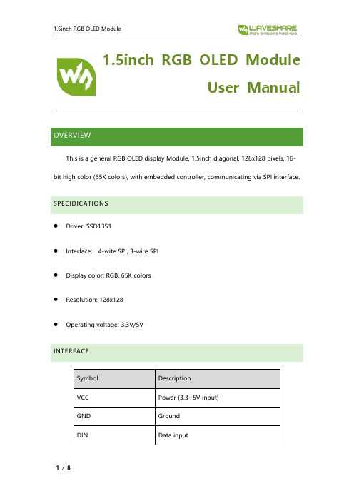
1.5inch RGB OLED ModuleUser ManualOVERVIEWThis is a general RGB OLED display Module, 1.5inch diagonal, 128x128 pixels, 16-bit high color (65K colors), with embedded controller, communicating via SPI interface. SPECIDICATIONS⚫Driver: SSD1351⚫Interface: 4-wite SPI, 3-wire SPI⚫Display color: RGB, 65K colors⚫Resolution: 128x128⚫Operating voltage: 3.3V/5VINTERFACESymbol DescriptionVCC Power (3.3~5V input)GND GroundDIN Data inputCLK Clock data inputCS Chip selection, low activeDC 4-wire SPI: Data/Command selection(high for data, low for command)3-wire SPI: Connects to GND, keeps low RST Reset, low activeHARDWARE SETTINGThis OLED supports two communication types: 4-wire SPI and 3-wire SPI. There is solderable resistor on the backside, you can change it for related SPI.Factory setting is 4-wire SPI, that is BS0 set to 0.Note: The table show the connection of pinsBS CS D/C DIN CLK 4-wire SPI 0 Chip selection D/C MOSI SCK3-wire SPI 1 Chip selection GND MOSI SCK4-wire SPI: (Factory setting), BS set to 0 connect to GND. DIN should be connected to MOSI, and CLK should be connected to SCK.3-wire SPI: BS set to 1 connect to VCC, D/C should be connected to GND. DIN connect to MOSI and CLK connect to SCK.WORKING PROTOCOLSSD1351 is a Dot Matrix OLED/PLED controller for 128RGB*128 screen, embed 128*128*128 bits SRAM as display buffer. It supports 265k and 65k gray scale. Interface supports 8080, 8bit 6800, 3-wire SPI, 4-wire SPI and so on.For reducing the size and save IO resources, 1.5inch RGB OLED uses 4-wire SPI and 3-wire SPI communication.4WIRE-SPIUsing 4-wire SPI, you should first set the DC to 1 or 0 and then send data.If DC=1, the data sent is stored to SRAM of SSD1351 as display data. In this mode, the length of data should be more than 1 byte.If DC=0, the data sent is used as control command, the length of command is usually 1 byte.For more details, please refer to SSD1352 Datasheet Figure 8-53-WIRE SPIThe difference between 3-wire SPI and 4-wire SPI is that 3-wire adds one bit before the transmitting byte for stand of command/data instead of DC pin.If you use 3-wire SPI, make sure the DC pin is connected to GND. And the data transmitted are 9bit instead of 8bit.HOW TO USESTM32, Arduino and Raspberry Pi sample code is provided for this OLED. The sample code is used to draw shapes and display string.STM32CONNECTION:The demo code is based on XNUCLEO-F103RB1.5inch RGB OLED XNUCLEO-F103RBVCC 3V3/5VGND GNDDIN D11(PA7)CLK D13(PA5)CS D10(PB6)DC D7(PA8)RST D8(PA9)FILES:Project is built for MDK-ARM v5, generated by sTM32CubeMx.../Src:OLED_Driver.cpp: Bottom interface of OLED,provide the function of initialization and basic display and configuration.OLED_GFX.cpp: Display functions for OLEDASCII_Font.h: Font library, provide two English fonts (5*8 and 8*16)for display. ARDUINOCONNECTIONDemo code is based on UNO PLUS1.5inch RGB OLED UNO PLUSVCC 3V3/5VGND GNDDIN D11CLK D13CS D10DC D7RST D8FILESOLED_Driver.cpp: Bottom interface of OLED,provide the function of initialization and basic display and configuration.OLED_GFX.cpp: Display functions for OLEDASCII_Font.h: Font library, and a 5*7 array for OLED display data.RASPBERRY PICONNECTIONDemo code is based on Raspberry Pi 3B功能引脚开发板VCC 3V3/5VGND GNDDIN MOSICLK SCKCS CE0DC 24(BCM)RST 25(BCM) SETTING1. Enable SPI interface of Raspberry Pisudo raspi-configChoose Interfaces Options->SPI->yes2. Install librariesFor libraries installing, please refer to:https:///wiki/Libraries_Installation_for_RPi FILESYou need to copy the demo code (Raspberry Pi one) to your Pi. We copy to /home/pi of Raspberry Pi.Enter the folder (demo code) and execute ls:cambriab.ttf:Font file for string display.mian.py: Main function file.You can use command sudo python main.py to run the demo code.。
图形编程模块使用手册(IEC模块库)-329

UCTRONICS 3.5英寸 HDMI TFT LCD 触摸屏显示模块说明书
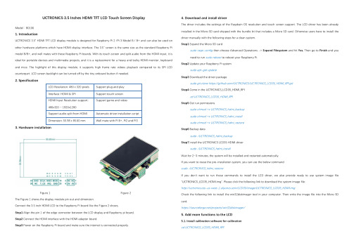
UCTRONICS 3.5 Inches HDMI TFT LCD Touch Screen DisplayModel:B01061.IntroductionUCTRONICS 3.5" HDMI TFT LCD display module is designed for Raspberry Pi 2 /Pi 3 Model B / B+ and can also be used on other hardware platforms which have HDMI display interface. The 3.5" screen is the same size as the standard Raspberry Pi model B/B+, and well mates with these Raspberry Pi boards. With its touch screen and split audio from the HDMI input, it is ideal for portable devices and multimedia projects, and it is a replacement for a heavy and bulky HDMI monitor, keyboard and mice. The highlight of this display module, it supports high frame rate videos playback compared to its SPI LCD counterpart. LCD screen backlight can be turned off by the tiny onboard button if needed.2.Specification3.Hardware installationFigure 1 Figure 2The Figure 1 shows the display module pin out and dimension.Connect the 3.5 inch HDMI LCD to the Raspberry Pi board like the Figure 2 shows,Step1 Align the pin 1 of the edge connector between the LCD display and Raspberry pi board,Step2 Connect the HDMI interface with the HDMI adapter board.Step3 Power on the Raspberry Pi board and make sure the internet is connected properly.4.Download and install driverThe driver includes the settings of the Raspbain OS resolution and touch screen support. The LCD driver has been already installed in the Micro SD card shipped with the bundle kit that includes a Micro SD card. Otherwise users have to install the driver manually with the following steps for a clean system.Step1 Expand the Micro SD cardsudo raspi-config then choose Advanced Operations -> Expand Filesystem and hit Yes. Then go to Finish and you need to run sudo reboot to reboot your Raspberry Pi.Step2 Update your Raspberry Pi systemsudo apt-get updateStep3 Download the driver packagesudo git clone https:///UCTRONICS/UCTRONICS_LCD35_HDMI_RPI.gitStep4Come in the UCTRONICS_LCD35_HDMI_RPIcd UCTRONICS_LCD35_HDMI_RPIStep5 Get run permissionssudo chmod +x UCTRONICS_hdmi_backupsudo chmod +x UCTRONICS_hdmi_installsudo chmod +x UCTRONICS_hdmi_restoreStep6 Backup datasudo ./UCTRONICS_hdmi_backupStep7 install the UCTRONICS LCD35 HDMI driversudo ./UCTRONICS_hdmi_installWait for 2~3 minutes, the system will be installed and restarted automatically.If you want to reuse the pre-installation system, you can use the below commandsudo ./UCTRONICS_hdmi_restoreIf you don’t want to run those commands to install the LCD driver, we also provide ready to use system image file “UCTRONICS_LCD35_HDMI.img". Please click the following link to download the system image file:/LCD35/image/UCTRONICS_LCD35_HDMI.imgCheck the following link to install the win32diskimager tool in your computer. Then write the image file into the Micro SD card.https:///projects/win32diskimager/5.Add more functions to the LCD5.1. Install calibration software for calibrationcd UCTRONICS_LCD35_HDMI_RPIsudo unzip Xinput-calibrator_0.7.5-1_armhf.zipcd xinput-calibrator_0.7.5-1_armhf/sudo dpkg -i -B xinput-calibrator_0.7.5-1_armhf.deb5.2. Install virtual keyboardStep1 Execute the following commands to install the corresponding softwaresudo apt-get updatesudo apt-get install matchbox-keyboardsudo nano /usr/bin/toggle-matchbox-keyboard.shStep2 Copy the following contents to toggle box - keyboard. sh, save the exit#!/bin/bash#This script toggle the virtual keyboardPID=pidof matchbox-keyboardif [ ! -e $PID ]; thenkillall matchbox-keyboardelsematchbox-keyboard -s 50 extended&fiStep3 Execute the following commandsudo chmod +x /usr/bin/toggle-matchbox-keyboard.shsudo mkdir /usr/local/share/applicationssudo nano /usr/local/share/applications/toggle-matchbox-keyboard.desktopStep4 Copy the following contents to toggle - matchbox - keyboard. Desktop, save exit[Desktop Entry]Name=Toggle Matchbox KeyboardComment=Toggle Matchbox Keyboard`Exec=toggle-matchbox-keyboard.shType=ApplicationIcon=matchbox-keyboard.pngCategories=Panel;Utility;MBX-MB-INPUT-MECHANSIM=TrueStep5 To perform the following command, note that this step must use the "PI" user permission, and if the administrator privileges are used, the file will not be foundnano ~/.config/lxpanel/LXDE-pi/panels/panel Step6 Find similar commands (different versions of ICONS may differ)Plugin {type = launchbarConfig {Button {id=lxde-screenlock.desktop}Button {id=lxde-logout.desktop}}Step7 Add the following code to add a Button itemButton {id=/usr/local/share/applications/toggle-matchbox-keyboard.desktop}Step8 To restart the system with the following command, you can see a virtual keyboard icon in the top left corner sudo reboot5.3. How to add new ICON to desktop?If it's just a folder, add it directly to the desktop.If it is an executable, follow these steps:Step1: choose the Directory Tree -> / -> usr -> share ->applications folderStep2: choose a icon you want to linkStep3: choose edit -> create link... ->Desktop ->OK6.Contact usIf need any further support, feel free to contact us.Website: Email: *********************Tel: +86 025 ********。
普微38英寸320×240点阵液晶显示模块LM2068E系列
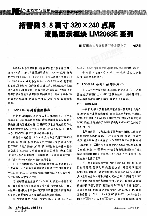
拓蕾徽3.8英寸320×240点阵液暑显示模块LM2068E系列●深圳市拓普微科技开发有限公司郭强LMz068E系列是深圳市拓普微科技开发有限公司开发的3.8英寸QvGA液晶显示模块(320×240点阵,模块尺寸为99.5mm×71.1mm×10.omm,视窗尺寸为79.8mm×60.6mm,点大小为o.24mm×o.24mm),具有结构紧凑、体积轻巧、点阵细腻、对比度高、功耗低、抗干扰强等显著特点,非常适用于医疗仪器、电力仪表、便携式仪器等需要多内容显示或多图形多曲线显示,要求体积小、功耗低等应用领域,例如心电图机、uPs电源、数据采集仪等。
1LM2068E系列的主要特点拓普微LM2068E系列液晶显示模块除具有上述显著特点外,还可提供蓝底白字、白底黑字两种显示效果以供选择,并内置升压电路,工程师可以很方便地应用单电源供电设计电路(3.3v/5V可选),且该模块采用了超亮白色LED背光,保证了极佳的显示效果。
最值得一提的是,LM2068E系列产品采用了EPS()N公司的s1D13700作为液晶显示控制器。
该控制器是替代sEDl335的升级换代产品,接口特性和软件指令基本完全兼容sEDl335,并具有更强大的功能,为正在因SEDl335停产而苦恼的工程师提供了全新的解决方案。
以下是LM2068E系列产品的应用特性;①显示功能强大,可以多画面重叠显示,有多种显示合成关系。
此合成关系将提高显示效果,可实现以像素为单位的上、下、左、右的卷动功能,光标可以上下左右移动,为数据的写入带来了方便。
②能够管理虚拟显示RAM区,即设置一个显示区域。
该区域可以大于实际的显示区域,但管理是同实际显示区域一样,使用水平卷动的方法可以将该部分的内容显示出来。
这样做可以实现曲线连续跟踪的效果。
③内置通用的AScII西文字库以及32KB显示sRAM,节省外部电路空间,同时也提供足够的显示空间。
液晶显示模块使用手册说明书

液晶显示模块使用手册 FM FM12832D 12832D台 湾 (重庆市) 汇 福 电子有限公司网 站: 邮 件: cqs.hf cqs.hf@@ cqshf cqshf@@ 电 话话: 023023023--6380 0611 6353 72396380 0611 6353 7239 传 真真: 023023023--6353 7239 6353 7239手 机: 139****7064/131****5453联系人联系人:: 王王 强 ( (先生先生先生) / ) / ) / 李李 培 英 ( (小姐小姐小姐)) 地址地址::重庆市重庆市渝中区中山三路渝中区中山三路86号重百电子城二楼1818--2号 地址地址::重庆市渝中区新华路220号B2楼实田电子城18区1919--20号台 湾 (重庆市) 汇 福 电子有限公司网 站: 邮 件: cqs.hf cqs.hf@@ cqshf cqshf@@ 电 话话: 023023023--6380 0611 6353 72396380 0611 6353 7239 传 真真: 023023023--6353 7239 6353 7239手 机: 139****7064/131****5453联系人联系人:: 王王 强 ( (先生先生先生) / ) / ) / 李李 培 英 ( (小姐小姐小姐)) 地址地址::重庆市渝中区中山三路86号重百电子城二楼1818--2号 地址地址::重庆市渝中区新华路220号B2楼实田电子城18区1919--20号目 录录(一)概述 (1)(二) 外形尺寸图 (1)(三) 模块主要硬件构成说明 (2)(四) 模块的外部接口 (3)(五) 指令说明 (4)(六) 读写操作时序 (6)(七) 应用举例 (7)概述一.概述FM12832是一种图形点阵液晶显示器,它主要由行驱动器/列驱动器及128×32全点阵液晶显示器组成。
4.3寸TFT显示器使用手册
4.3寸TFT显示器 SM.04TL/C使用手册出版状态:标准产品版本: V1.0上海新时达电气股份有限公司版权所有,保留一切权利在没有得到本公司许可时,任何单位和个人不得擅自摘抄、复制本书(软件等)的一部分或全部,不得以任何形式(包括资料和出版物)进行传播。
版权所有,侵权必究。
内容如有改动,恕不另行通知。
Copyright© by Shanghai STEP Electric Co., Ltd.All rights reservedThe information in this document is subject to change without notice . No partof this document may in any form or by any means(electronic,mechanical,micro-coping,photocopying,recording or otherwise)be reproduced,stored in a retrival system or transmitted without prior writtenpermission from Shanghai STEP Electric Corporation一、外形图片及尺寸图1 4.3寸TFT显示器外形图(竖显和横显)图2 4.3寸TFT显示器尺寸(mm)二、功能特点1、适用于新时达串行通讯系统;2、采用4.3寸TFT作为显示界面,真彩色显示(16位色),分辨率为480×272;3、能够显示电梯楼层、运行方向和背景图片;4、显示内容均存储在显示器内,可通过USB端口对其进行更新;5、即可做横显,也可以做竖显,通过拨码开关设置;6、显示界面尺寸:97mm×55mm。
三、端口定义图3 SM.04TL/C端子端子定义如下表所示:端子号端子定义插座型号插头型号JP1 电源与通讯 S4B-XH-A XHP-4JP2 上召按钮接口CH2510-4AW CH2510-4YJP3 下召按钮接口JP4 锁梯JP1为电源和通讯线接口,其接线示意图如图4所示:图4 电源和通讯接线示意图JP2、JP3和JP4的1脚和2脚接按钮灯,3脚和4脚接按钮的输入,如图5所示:图5 按钮接线示意图拨码开关说明如下:序号位号功能SW1.1 拨到“ON”,进入楼层设置状态,用于设置当前楼层,按上召按钮楼层值增加,按下召按钮楼层值减少,设置完毕后将其拨到“OFF”状态。
7[1].0寸TFT模块详细说明书
![7[1].0寸TFT模块详细说明书](https://img.taocdn.com/s3/m/03b98002bed5b9f3f90f1ca0.png)
NHC_36彩色液晶显示控制模块使用说明一、N HC_36型显示控制模块的特点。
A:安装方便,板尺寸为168mm╳116mm,安装孔Ф3mm,四个安装孔位置为162mm╳110mm,高度为14mm。
B:微处理器可以随时读写显示存储器,而不影响显示效果,即显示不会出现“雪花”。
C:与微处理器接口连接简单,接口的读、写操作兼容8031总线时序。
D:有两页显示缓存,可以任意设定显示页和操作页。
二、物理特性:三、电器参数:NOTE1:最小电流的条件是电源4.8V,不对模块操作,液晶屏幕显示全黑。
最大电流的条件是电源5.2V,对控制卡进行高速逻辑写操作,屏幕显示全白。
四、MCU接口定义用户板和NHC_36控制模块的连接(J1)采用21线2.54mm间距单排插针。
对液晶的操作采用标准intel总线时序(8031总线时序)。
管脚图如下:(顶视图)如果第18管脚“RD\”不用时,接上拉电阻五、NHC_36液晶控制板与微处理器的接口时序接口时序与8031的总线时序相同时序:A0、A1/WR、D7—D0(D7—D0(READ时序特性参数六、指令介绍及编程方法:CS WR RD A1 A0 D0-D7H 任意任意任意任意操作无效L L H 0 0 写显示数据到LCDL H L 0 0 从LCD读数据L L H 0 1 写显示数据前用:设定行地址,地址0-233对应液晶屏从上到下1到234行L L H 1 0 设定列地址(0-479)L L H 1 1 设定显示页和操作页1.写指令和数据a)设定显示页和操作页地址。
(A1=A0=1,CS=0,WR=0)开机时先执行此操作再执行其他操作,工作中不需要换页时D4位设定操作页。
D0位设定显示页。
b)写行地址。
(A1=0,A0=1)c)写列地址高字节。
(A1=1,A0=0)d)写列地址低字节。
(A1=1,A0=0)e)写1个字节数据。
对应一个象素点。
(A1=0,A0=0)R2、R1、R0表示红色灰度,从000到111,灰度有8级R2为高灰度位,R0为低灰度位。